EP2406532B1 - Method to repair flexible fiber-reinforced pipe - Google Patents
Method to repair flexible fiber-reinforced pipe Download PDFInfo
- Publication number
- EP2406532B1 EP2406532B1 EP20100751348 EP10751348A EP2406532B1 EP 2406532 B1 EP2406532 B1 EP 2406532B1 EP 20100751348 EP20100751348 EP 20100751348 EP 10751348 A EP10751348 A EP 10751348A EP 2406532 B1 EP2406532 B1 EP 2406532B1
- Authority
- EP
- European Patent Office
- Prior art keywords
- stacks
- replacement
- tape
- stack
- undamaged
- Prior art date
- Legal status (The legal status is an assumption and is not a legal conclusion. Google has not performed a legal analysis and makes no representation as to the accuracy of the status listed.)
- Not-in-force
Links
- 238000000034 method Methods 0.000 title claims description 60
- 230000008439 repair process Effects 0.000 title claims description 38
- 239000000853 adhesive Substances 0.000 claims description 24
- 230000001070 adhesive effect Effects 0.000 claims description 24
- 239000000463 material Substances 0.000 claims description 22
- 238000005520 cutting process Methods 0.000 claims description 9
- 230000004888 barrier function Effects 0.000 claims description 8
- 230000001681 protective effect Effects 0.000 claims description 6
- 239000011241 protective layer Substances 0.000 claims description 6
- 239000004593 Epoxy Substances 0.000 claims description 5
- 238000000227 grinding Methods 0.000 claims description 5
- 230000006835 compression Effects 0.000 claims description 4
- 238000007906 compression Methods 0.000 claims description 4
- 238000007789 sealing Methods 0.000 claims description 4
- 239000004033 plastic Substances 0.000 claims description 3
- 238000005452 bending Methods 0.000 claims description 2
- 238000004023 plastic welding Methods 0.000 claims description 2
- 239000010410 layer Substances 0.000 description 39
- 239000002131 composite material Substances 0.000 description 35
- 230000008569 process Effects 0.000 description 20
- 238000005299 abrasion Methods 0.000 description 9
- 230000002787 reinforcement Effects 0.000 description 8
- 238000011065 in-situ storage Methods 0.000 description 6
- 238000009434 installation Methods 0.000 description 6
- 238000004519 manufacturing process Methods 0.000 description 5
- 239000011800 void material Substances 0.000 description 5
- 239000000126 substance Substances 0.000 description 4
- 230000008901 benefit Effects 0.000 description 2
- 238000001125 extrusion Methods 0.000 description 2
- 229920000647 polyepoxide Polymers 0.000 description 2
- 238000003466 welding Methods 0.000 description 2
- LFQSCWFLJHTTHZ-UHFFFAOYSA-N Ethanol Chemical compound CCO LFQSCWFLJHTTHZ-UHFFFAOYSA-N 0.000 description 1
- 230000004075 alteration Effects 0.000 description 1
- 230000000712 assembly Effects 0.000 description 1
- 238000000429 assembly Methods 0.000 description 1
- 239000011230 binding agent Substances 0.000 description 1
- 238000001311 chemical methods and process Methods 0.000 description 1
- 239000012459 cleaning agent Substances 0.000 description 1
- 238000010276 construction Methods 0.000 description 1
- 238000001816 cooling Methods 0.000 description 1
- 229920001577 copolymer Polymers 0.000 description 1
- 230000003111 delayed effect Effects 0.000 description 1
- 238000001035 drying Methods 0.000 description 1
- 239000000428 dust Substances 0.000 description 1
- 125000003700 epoxy group Chemical group 0.000 description 1
- 239000003822 epoxy resin Substances 0.000 description 1
- 239000004744 fabric Substances 0.000 description 1
- 239000012530 fluid Substances 0.000 description 1
- LNEPOXFFQSENCJ-UHFFFAOYSA-N haloperidol Chemical compound C1CC(O)(C=2C=CC(Cl)=CC=2)CCN1CCCC(=O)C1=CC=C(F)C=C1 LNEPOXFFQSENCJ-UHFFFAOYSA-N 0.000 description 1
- 239000002648 laminated material Substances 0.000 description 1
- 230000001050 lubricating effect Effects 0.000 description 1
- 230000007246 mechanism Effects 0.000 description 1
- 239000012528 membrane Substances 0.000 description 1
- 239000000203 mixture Substances 0.000 description 1
- 239000002245 particle Substances 0.000 description 1
- 239000003208 petroleum Substances 0.000 description 1
- 230000002265 prevention Effects 0.000 description 1
- 238000010791 quenching Methods 0.000 description 1
- 230000000171 quenching effect Effects 0.000 description 1
- 239000003566 sealing material Substances 0.000 description 1
- 238000000926 separation method Methods 0.000 description 1
- 239000002904 solvent Substances 0.000 description 1
- 238000006467 substitution reaction Methods 0.000 description 1
- 229920001169 thermoplastic Polymers 0.000 description 1
- 239000004416 thermosoftening plastic Substances 0.000 description 1
Images






Classifications
-
- F—MECHANICAL ENGINEERING; LIGHTING; HEATING; WEAPONS; BLASTING
- F16—ENGINEERING ELEMENTS AND UNITS; GENERAL MEASURES FOR PRODUCING AND MAINTAINING EFFECTIVE FUNCTIONING OF MACHINES OR INSTALLATIONS; THERMAL INSULATION IN GENERAL
- F16L—PIPES; JOINTS OR FITTINGS FOR PIPES; SUPPORTS FOR PIPES, CABLES OR PROTECTIVE TUBING; MEANS FOR THERMAL INSULATION IN GENERAL
- F16L55/00—Devices or appurtenances for use in, or in connection with, pipes or pipe systems
- F16L55/16—Devices for covering leaks in pipes or hoses, e.g. hose-menders
- F16L55/168—Devices for covering leaks in pipes or hoses, e.g. hose-menders from outside the pipe
- F16L55/1683—Devices for covering leaks in pipes or hoses, e.g. hose-menders from outside the pipe by means of a patch which is fixed on the wall of the pipe by means of an adhesive, a weld or the like
-
- B—PERFORMING OPERATIONS; TRANSPORTING
- B29—WORKING OF PLASTICS; WORKING OF SUBSTANCES IN A PLASTIC STATE IN GENERAL
- B29C—SHAPING OR JOINING OF PLASTICS; SHAPING OF MATERIAL IN A PLASTIC STATE, NOT OTHERWISE PROVIDED FOR; AFTER-TREATMENT OF THE SHAPED PRODUCTS, e.g. REPAIRING
- B29C73/00—Repairing of articles made from plastics or substances in a plastic state, e.g. of articles shaped or produced by using techniques covered by this subclass or subclass B29D
- B29C73/04—Repairing of articles made from plastics or substances in a plastic state, e.g. of articles shaped or produced by using techniques covered by this subclass or subclass B29D using preformed elements
- B29C73/06—Repairing of articles made from plastics or substances in a plastic state, e.g. of articles shaped or produced by using techniques covered by this subclass or subclass B29D using preformed elements using plugs sealing in the hole
-
- B—PERFORMING OPERATIONS; TRANSPORTING
- B29—WORKING OF PLASTICS; WORKING OF SUBSTANCES IN A PLASTIC STATE IN GENERAL
- B29C—SHAPING OR JOINING OF PLASTICS; SHAPING OF MATERIAL IN A PLASTIC STATE, NOT OTHERWISE PROVIDED FOR; AFTER-TREATMENT OF THE SHAPED PRODUCTS, e.g. REPAIRING
- B29C73/00—Repairing of articles made from plastics or substances in a plastic state, e.g. of articles shaped or produced by using techniques covered by this subclass or subclass B29D
- B29C73/04—Repairing of articles made from plastics or substances in a plastic state, e.g. of articles shaped or produced by using techniques covered by this subclass or subclass B29D using preformed elements
- B29C73/10—Repairing of articles made from plastics or substances in a plastic state, e.g. of articles shaped or produced by using techniques covered by this subclass or subclass B29D using preformed elements using patches sealing on the surface of the article
Definitions
- the present disclosure relates to flexible composite pipe for conducting petroleum or other fluids subsea or on land and a method of repairing the same.
- a composite flexible may be formed in part from composite tape stacks.
- Composite tape stacks may be formed from a plurality of thin tape strips. The composite tape stacks may then be helically wound onto a pipe structure. During operation a pipe may be damaged, which may result in a stopping of production and/or operation so that a repair or replacement of the damaged pipe may be made.
- the present disclosure relates to a method to repair damaged composite flexible pipe.
- Embodiments disclosed herein relate to one or more embodiments of and methods to repair a flexible pipe.
- a method to repair damaged flexible fiber-reinforced pipe which includes a plurality of helically-wrapped stacks of laminated strips of material is disclosed. The method includes removing a portion of existing stacks from a damage location, abrading a surface of replacement stacks to be installed at the damage location, applying an adhesive to the abraded surface of the replacement stacks, installing replacement stacks to the damage location, binding the replacement stacks to remaining existing stacks with the applied adhesive, and installing a replacement jacket over the replacement stacks.
- the present disclosure may comprise a repair method for composite pipe similar to that disclosed in U.S. Patent Number 6,491,779, filed on April 24, 2000 , entitled “Method of Forming a Composite Tubular Assembly," U.S. Patent No. 6,804,942, filed on September 27, 2002 , entitled “Composite Tubular Assembly and Method of Forming Same,” and U.S. Patent No. 7,254,933, filed on May 6, 2005 , entitled “Anti-collapse System and Method of Manufacture,”.
- the method may also be suitable for repairing any bonded or unbonded flexible pipe structure that employs composite materials for hoop reinforcement and/or tensile reinforcement.
- One or more embodiments of the present disclosure are related to repair procedures directed to repair the hoop or tensile reinforcement layers of a composite flexible pipe in-situ, thereby reducing the amount of time a rig may be delayed from production and/or operation.
- a pipe structure 12 may be helically wrapped with a first layer of composite tape stacks 14 in a first orientation and a second layer of composite tape stacks 16 which may be counter wound with respect to stacks 14 in an opposite orientation.
- An anti-abrasive layer 18 may be disposed between stacks 14 and stacks 16 and a jacket 20 may cover the layers of the pipe 10 to provide external protection.
- Figure 1 depicts a relatively simple composite pipe structure 10, those skilled in the art will appreciate that a composite pipe 10 may include additional and/or different layers, including liners, hoop-stress reinforcement layers, anti-wear layers, lubricating layers, tensile reinforcement layers, anti-extrusion layers, membranes, and/or any other layers as may be included in a composite flexible fiber-reinforced pipe.
- the stack layers 102 and 104 may comprise helically wrapped stacks of laminated material.
- the stacks may be made of non-metallic fiber-reinforced tapes that may be laminated and bonded together as a single structural member.
- the individual layers of the stacks may include UD (unidirectional) tape or other structural and/or reinforced tape.
- the repair methods as described in embodiments of the present disclosure may be performed when an outer jacket and one or more layers of helically wrapped stacks that may include the hoop and/or tensile reinforcement layers are damaged.
- embodiments of the present disclosure may include a process of removing damaged stacks 100, a process of installing replacement stacks 200, and a process of sealing and/or covering the damaged area 300.
- any or all operational or installation loads may be removed from the damaged section of pipe, which may include pressure loads, bending loads, tension loads, torque loads, and/or any other loads that may be acting on the damaged area of pipe.
- the composite pipe may be stabilized and any stored energy may be released and/or controlled, and the pipe may be removed from service and all valves and flow prevention devices and/or methods may be activated.
- a tape stack refers to stacks of composite material that may be attached to a pipe and may form the pipe structure.
- a tape stack may include one or more non-metallic fiber-reinforced tapes.
- Undamaged stack refers to tape stacks that are still attached to the pipe but have not been damaged.
- Undamaged stacks may include tape stacks that have a damage portion removed therefrom.
- a damaged stack refers to a portion of the tape stack that may have suffered damage.
- a replacement stack refers to a stack of composite material the same as or similar to the composition of the tape stack.
- the replacement stack may be a partial length of tape stack.
- Barrier tape may be a tape that may allow for relative movement between layers that may be on each side of the barrier tape layer. Barrier tape may also provide protection to surfaces to which it may be applied.
- U-tape may be made of the same tape as that barrier tape, or may be a different tape such as a "Z" shaped, or "Z-tape” used in the manufacture of composite flexible pipe.
- the U-tape may not have a "U” shape as manufactured, but may be manipulated into forming a "U” shape. Accordingly, the U-tape may be provided from a roll or sheets of tape and then manipulated during installation into a "U” shape.
- a single strip may be a single strip of the material which makes up the tape stacks or replacement stacks, such as a strip of UD tape or other fiber-reinforced non-metallic tape strip. As described above, the tape stacks and replacement stacks may be made of multiple layers which may be similar to the single strip.
- a protective layer may be a tape layer or an applied paste, gel, or other material which may provide a sealing layer and/or a binding layer or may be made from the barrier tape.
- a jacket may be made from extruded material, and the replacement jacket may be a portion of a jacket. The replacement jacket may be welded to the undamaged outer jacket of the pipe. The replacement jacket may also be a helical tape wrap applied externally to the undamaged jacket, covering the damaged section. The replacement jacket may also be a heat shrink tube or heat shrink wrap applied externally to the undamaged jacket, covering the damaged section.
- a protective exterior wrap may be a tape layer applied to the surface of the pipe or may be shrink-wrap and/or self-adhering tape, such as ethylene propylene copolymer tape. Adhesives may be epoxies, epoxy resins, and/or other binding agents and/or materials known in the art.
- an outer jacket that may be damaged may be removed at step 105.
- a strap may be applied to the surface of the pipe above and/or below the area to be removed.
- the strap may be used to serve as a guide for marking and cutting throughout the repair.
- Chalk, wax pencil, or other suitable markings may be made to the exterior of the pipe to outline or demark the desired area for repair.
- a hot knife may be used to cut through the material of the outer jacket.
- a circular saw, utility knives, or other cutting instruments may be used to cut away the damaged area of the outer jacket.
- a jacket window may be formed.
- the jacket window may be defined by the edge of the undamaged jacket that remains surrounding the damaged area of the pipe.
- the jacket window may allow access to damaged layers of the pipe.
- an edge of the jacket window may be a distance away from the damaged stacks. The distance may be such as to allow for some manipulation of the undamaged portions of the tape stacks (i.e., undamaged stacks).
- a protective layer that may be the first layer beneath the jacket may be removed from around the damaged location.
- the outer layer may be an anti-torque layer which may include binding tape, such as Z-tape used in the manufacture of composite flexible pipe.
- a border of this layer may remain, so that an edge of the layer may be exposed within the jacket window.
- a 2.54cm (one inch) border may remain visible and covering and protecting undamaged stacks in the jacket window.
- the amount of exposed outer layer may vary, and may even be completely removed from the jacket window,.
- the damaged portions of the tape stacks may be removed.
- the portion which is damaged may be removed, so that what remains may be partial sections of exposed portions of the stacks that remain directly attached to the pipe (i,e., the undamaged stacks).
- a cutting tool may be used to remove the damaged stacks.
- the cutting tool may be a circular saw, a rotary cutting wheel, or any other cutting tool known in the art that may cut through the tape stacks.
- 10.16 cm (4") or more of undamaged stacks may be left visible within the jacket window to be manipulated.
- the cuts of adjacent damaged stacks may be made with some amount of separation or linear distance along the length of the tape stacks between where the cuts are made.
- the length of exposed tape stacks may vary to be longer or shorter than 10.16 cm (4").
- the damage location following removal of the damaged stacks, may be cleaned.
- the damage location may be cleaned with a solvent, clean compressed air, alcohol wipes, and/or any other cleaning agent or device that may remove dust and other particles and prepare the damage location for the repair.
- the damage location may also be dried with a moisture absorbing cloth, forced air convection (with or without heated air), or other drying means known in the art.
- lengths of replacement stacks may be cut to size.
- Each damaged stack that may be removed may have a custom replacement stack cut to fit. Accordingly, the replacement stacks may fit into a void created by the removed damaged stacks.
- lengths of U-tape may be cut.
- the U-tape may be a flat tape which may have a linear length, which may be a length along the length of a tape stack and a width which may be a width designed to wrap around a repaired tape stack.
- Each replacement stack may have one section of U-tape cut to size.
- the linear (i.e., axial) length of the U-tape may extend longer than the replacement stacks to which they may correspond.
- the U-tape for a particular replacement stack may be about 20.32 cm (8") longer than the replacement stack it may correspond to.
- lengths of single strips may be cut the same length as the U-tape.
- Each replacement stack may have two corresponding single strips.
- the length of the U-tape and single strips may vary. Further, the U-tape and the single strips may be of different lengths, such that one may be longer than the other in length along the stack.
- all contact surfaces may be abraded to allow for a clean bonding between different elements during the repair procedure.
- the contact surfaces may include the surfaces of the U-tape, both sides of the single strips, all sides of the replacement stacks, and surfaces of the undamaged stacks.
- the abrasion may be made by a physical or chemical process. Physical abrasion may be accomplished by sanding, grinding, filing, or other physical abrasion tools or methods. Chemical abrasion may be accomplished by chemicals which may etch the surface of the composite material. After abrasion, the damage location may be cleaned, as describe above, which may allow for clean contact surfaces for binding during the repair process.
- the undamaged stacks may be lifted to expose the undamaged portion of pipe beneath.
- the length of undamaged stack to be lifted may correspond to the additional length of the U-tape beyond the length of its corresponding replacement stack.
- the additional length may be a distance of overlap that the U-tape and the single strips may have with the undamaged stacks.
- a U-tape may be cut to be 20.32 cm (8") longer than a corresponding replacement stack, accordingly, each side of the undamaged stacks may be lifted at least 10,16 cm (4") to accommodate the full length of the U-tape, and thereby creating a distance of overlap of 10.16 cm (4") for each side of the undamaged stack.
- the U-tape may be placed beneath the lifted undamaged stacks. A distance of overlap for each end of the exposed undamaged stack may exist due to the extended length of the U-tape.
- a first single strip may be placed within the U-tape, beneath the lifted undamaged stack and parallel to the direction of the tape stack.
- Adhesive may be applied between the first single strip and the U-tape into which it may be placed. Accordingly, a bond may be formed between the first single strip and the U-tape.
- the undamaged stacks may be released.
- Adhesive may be applied to the under side of the undamaged stacks and/or the first single strip so that a bond may be formed between the first single strip and the undamaged stacks.
- a replacement stack may be placed on the first single strip within the U-tape and between the ends of the undamaged stacks defining a void representing the removed damaged stack.
- Adhesive may be applied between the first single strip and the replacement stack so that a bond may be formed between the two elements.
- the replacement stack may be placed in the center of the U-tape so that a continuous section of repaired tape stack may be formed which may include the disconnected undamaged stacks and the replacement stack placed therebetween.
- a second single strip may be placed on the surface of the replacement stack and may extend over the surface of the undamaged stack for the distance of overlap. Adhesive may be applied between these layers so that a bond may be formed therebetween. The second single strip may be placed so that the additional length may extend in either direction for the length of the overlap.
- the U-tape may be folded over and/or closed so that a single continuous repaired tape stack may be formed.
- Adhesive may be applied to the inner surface of the U-tape and/or the top surface of the second single strip, thereby forming a bond between the layers.
- Steps 202 through 218 may be repeated for each damaged stack.
- FIG. 8 A cross-sectional view of a repaired tape stack in accordance with embodiments of the present disclosure, and particularly process 200A, is shown in Figures 8 , 9A-9C , and 12A-12C , which will be described below.
- replacement stacks may be cut to size. Additionally, U-tape and single strips may be cut to size for each replacement stack. The U-tape and the single strips may be cut for a distance of overlap, similar to that described above. Further, the U-tape and single strips may be the same or different lengths.
- a replacement assembly may be assembled (see Figure 12A ).
- the surfaces of the replacement stack may be abraded.
- surfaces of the single strips may be abraded.
- the replacement assembly may be constructed by applying an adhesive to the abraded surfaces of the replacement stack and a contact surface of the single strips.
- a single strip may be applied to the top and the bottom of the replacement stack, thereby forming a substantially "I" shape, in which the replacement stack may be a central body and the two single strips may extend for the distance of overlap in each direction.
- step 236 the undamaged stacks may be lifted to expose the undamaged portion of pipe as described above in step 208 of process 200A.
- the U-tape may be placed beneath the lifted undamaged stack, so that the distance of overlap of the U-tape may extend under each exposed end of the undamaged stack.
- step 240 the replacement assembly constructed in step 234 may be placed in the U-tape.
- An adhesive may be applied to the bottom of the replacement assembly and/or the U-tape so that a bond may be formed between the two.
- each end of the top single strip of the replacement assembly may be lifted so that the undamaged stacks may be released, in step 244 (see Figure 12B ). Then, in step 246, each end of the lifted top single strip may be released, thereby creating a continuous length of repaired tape stack, which may include the replacement assembly and the undamaged stacks (see Figure 12C ). Further, adhesive may be applied between the single strips and the lifted portions of the undamaged stack to form a bond therebetween.
- adhesive may be applied to the U-tape, and it may be sealed, to thereby create the repaired tape stack.
- Steps 232-248 may be repeated for each damaged stack.
- FIG. 8 and 9A-9C A cross-sectional view of a repaired tape stack in accordance with embodiments of the present disclosure, and particularly process 200B, is shown in Figures 8 and 9A-9C , which will be described below.
- lengths of replacement stacks may be cut to size. Each damaged stack that may be removed may have a custom replacement stack cut to fit.
- the replacement stacks may be cut to a length that extends farther than the void created by the removed damaged stacks.
- the length of the replacement stacks may be cut to be 20.32 cm (8 ") longer than the void created by removal of the damaged stacks.
- the additional length of the replacement stacks as compared to the void may be varied, and particularly is not limited to additional 20.32 cm (8").
- lengths of U-tape and single strips may be cut, as described above with respect to step 202 of process 200A. The lengths of U-tape and single strips may be longer than the length of the replacement stacks.
- the undamaged stacks and the replacement stacks may be grinded to form stair-step engagement surfaces, as shown in Figures 1OB and 1OC . Accordingly, the surface of contact between the replacement stack and the undamaged stacks may be increased, which may allow for a stronger bond between the replacement stacks and the undamaged stacks.
- the replacement stacks may be grinded to match the stair-step pattern of the corresponding undamaged stacks, which may optimize the contact surfaces.
- the grinding may be made with a suitable grinding tool, which may grind through layers of the tape stacks.
- all contact surfaces may be abraded, which may allow for a secure bonding between different elements during the repair procedure.
- the contact surfaces may include the surfaces of the U-tape, both sides of the single strips, all sides of the replacement stacks, and surfaces of the undamaged stacks including the stair-step portions.
- the abrasion may be made my physical or chemical means. After abrasion, the damage location may be cleaned, as describe above, which may allow for clean contact surfaces for binding during the repair process.
- the undamaged stacks may be lifted to expose the undamaged portion of pipe beneath.
- the length of undamaged stack to be lifted may correspond to the additional length of the U-tape beyond the length of its corresponding replacement stack.
- the additional length may be a distance of overlap that the U-tape may have with the undamaged stacks, as described above.
- the U-tape may be placed beneath the lifted undamaged stacks, and may cover the distance over overlap.
- a first single strip may be placed within the U-tape, beneath the lifted undamaged stack.
- Adhesive may be applied between the first single strip and the U-tape into which it may be placed. Accordingly, a bond may be formed between the first single strip and the U-tape.
- the undamaged stacks may be released.
- Adhesive may be applied to the under side of the undamaged stacks and/or the first single strip so that a bond may be formed between the first single strip and the undamaged stacks.
- a replacement stack may be placed on the first single strip within the U-tape and between the ends of the undamaged stacks defining an area representing the removed damaged stack.
- the stair-step surfaces may contact.
- Adhesive may be applied between the first single strip and the replacement stack so that a bond may be formed between the two elements.
- the replacement stack may be placed in the center of the U-tape so that a continuous section of repaired tape stack may be formed which may include the disconnected undamaged stacks and the replacement stack placed therebetween. Further, adhesive may be applied between the undamaged stacks and the replacement stack, so that all of the surfaces of the stair-step may be bonded to each other.
- a second single strip may be placed on the surface of the replacement stack and may extend over the surface of the undamaged stack for the distance of overlap. Adhesive may be applied between these layers so that a bond may be formed therebetween. The second single strip may be placed so that the additional length may extend in either direction for the length of the overlap.
- the U-tape may be folded over and/or closed so that a single continuous repaired tape stack may be formed.
- Adhesive may be applied to the inner surface of the U-tape and/or the top surface of the second single strip, thereby forming a bond between the layers.
- FIG. 10A-10C A cross-sectional view of a repaired tape stack in accordance with embodiments of the present disclosure, and particularly process 200C, is shown in Figures 10A-10C , which will be described below.
- exemplary processes 200A, 200B, and 200C although the procedure may be performed in-situ, the cutting of lengths of replacement stacks, U-tape, and single strips may be preformed prior to arrival to the damage location, if the lengths desired are known in advance. Further, the replacement assemblies of procedure 200B may be assembled in advance, as well, if the dimensions are known in advance. In one or more embodiments of the present disclosure, replacement stacks and/or outer jacket repair material may be taken from a section of pipe that was manufactured to the same dimensional and material requirements as the pipe that may be repaired.
- a replacement jacket may be cut to fit the exposed surface of the damage location, which may fit to the jacket window. This may be performed in advance if the dimensions are known prior to arrival at the damage location or at any time during the repair process. Alternatively, the damaged jacket may be used as a template to cut the replacement jacket, if available.
- a protective layer may be placed and/or sealed over the repaired damage location.
- the protective layer may be made of barrier tape.
- the replacement jacket may be placed over the repaired damage location.
- the replacement jacket may be placed in the jacket window for installation. Further, the replacement jacket may be compressed into the jacket window. The compression may be accomplished by use of a ratcheting mechanism on tie-down straps or other compressive means known in the art.
- the jacket may be sealed to the pipe in step 320.
- the seal may be made by a weld, extruded material, and/or other sealing method or means. Specifically, the seams that may exist between the replacement jacket and the jacket window may be sealed.
- the welding may be done by a hot knife, a heat gun, torch, thermoplastic welder, or any other tool which may allow for plastic welding. After welding, the weld may be allowed to cool. When cooling, active quenching may be avoided.
- the extrusion may be made by an extruding gun, which may extrude plastic feedstock or other plastic or sealing material.
- the compression tie-down straps may then be removed. Any remaining unsealed seams may then be sealed. The compressive tie-down straps may then be reapplied to the repaired damage location to compress the jacket and stack assembly.
- a protective exterior wrap may be applied around the repaired damage location.
- the compressive tie-down straps may be removed prior to applying the protective exterior wrap. Further, after the protective exterior wrap may be applied, the tie-down straps may be re-installed to apply compression to the wrap, the jacket, and the stack assembly.
- a repaired tape stack 800 may be repaired in accordance with one or more embodiments of the present disclosure. Accordingly, a section of an undamaged pipe 801 may form the base of the repaired section. Undamaged pipe 801 may include multiple layers of a composite flexible pipe, as described above.
- U-tape 802 may be the first layer in contact with the surface of undamaged pipe 801.
- a first single strip 803 may be located on top of U-tape 802.
- In contact with first single strip 803 may be replacement stacks 804 and sections of undamaged stacks 805.
- a distance of overlap 810 and 811 may be provided to allow for a continuous repaired tape stack and may provide structural reinforcement to the repaired tape stack. Further, distances of overlap 810 and 811 may extend the same or different distances over each side of the undamaged stacks 805.
- the first single strip 803 may be omitted.
- a second single strip 806 may be applied above replacement stacks 804 and undamaged stacks 805, a second single strip 806 may be applied. Above second single strip 806, U-tape 802 may be folded and/or sealed over the replacement stack 804, the undamaged stacks 805, and single strips 803 and 806. Next, a protective layer 807 may be applied over the stack assembly to seal the replacement stacks within the pipe.
- a replacement jacket 808 may then cover the replacement stacks and the repaired region.
- a protective exterior wrap 809 may be applied to the surface of the pipe at the damage location to further seal and protect the repaired damage location.
- Adhesive may be applied between each layer. Application of the adhesive may be preceded by abrading the surface to which the adhesive may be applied.
- the abrasion may be either chemical or physical abrasion.
- Figures 9A-9C a cross-sectional schematic of the repair process in accordance with one or more embodiments of the present disclosure is shown. Particularly, Figures 9A-9C may schematically represent a cross-sectional view of the repair process in accordance with processes 200A and 200B.
- Figure 9A shows a schematic of a damaged stack 900, with stacks 920. Only a damaged stack is shown, and other layers of the pipe are omitted from the schematic.
- Stacks 920 may have a damaged section 921, which may include damage to multiple layers of the tape stacks 920.
- Figure 9B shows a representation of the tape stack 900 during the repair process. Specifically, undamaged stacks 905 may define a region of damaged stack 922. Damaged stack 922 may be removed by processes according to one or more embodiments of the present disclosure.
- Figure 9C shows the tape stack 900 as repaired in accordance with one or more embodiments of the present disclosure.
- undamaged stacks 905 and replacement stack 904 may define a continuous length of repaired tape stack 900.
- the repaired tape stack 900 may be bounded and supported by a first single strip 903 and a second single strip 906.
- single strips 903 and 906 may include distances of overlap 910 and 911.
- Figures 10A-10C a cross-sectional schematic of the repair process in accordance with one or more embodiments of the present disclosure is shown. Particularly, Figures 10A-10C may schematically represent a cross-sectional view of the repair process in accordance with process 200C.
- Figure 10A shows a schematic of a tape stack 1000, including stacks 1020 with a damaged section 1021, similar to that shown in Figure 9A .
- Figure 10B shows a representation of the tape stack 1000 during the repair process. Specifically, undamaged stacks 1005 may define a section of damaged stack 1022. Damaged stack 1022 may be removed by processes according to one or more embodiments of the present disclosure. Also shown in Figure 10B is the stair-step of undamaged stacks 1005.
- Figure 10C shows a repaired tape stack 1000 in accordance with one or more embodiments of the present disclosure.
- undamaged stacks 1005 and replacement stack 1004 may define a continuous length of repaired tape stack 1000.
- the repaired tape stack 1000 may be bounded and supported by a first single strip 1003 and a second single strip 1006.
- single strips 1003 and 1006 may include distances of overlap 1010 and 1011.
- the stair-step of replacement stack 1004 which may contact the stair-step of undamaged stacks 1005.
- Figures 11A-11C a cross-sectional schematic of the repair process in accordance with one or more embodiments of the present disclosure is shown. Particularly, Figures 11A-11C may schematically represent a cross-sectional view of the repair process as viewed along the length of the tapes. Particularly, Figures 11A-11C show the U-tape as applied.
- Figure 11A shows a replacement stack 1115 including a bottom single strip 1103, replacement stack 1104, and a top single strip 1106.
- the replacement stack is placed within a U-shaped tape, 1102.
- FIG 11B shows the U-tape 1102 sealed in accordance with one or more embodiments of the present disclosure.
- U-tape 1102 may be wrapped around replacement stack 1115.
- U-tape 1115 may be cut to length so that there is minimal increase in the height of the replacement stack 1115.
- U-tape 1102 may be fully wrapped, so as to maximize the contact surfaces.
- the height of the replacement stack may be increased.
- other lengths of overlap and height increase may be achieved.
- Figures 12A-12C a cross-sectional schematic of the repair process in accordance with one or more embodiments of the present disclosure is shown. Particularly, Figures 12A-12C may schematically represent a cross-sectional view of the repair process in accordance with process 200B.
- Figure 12A shows a cross-section of a replacement assembly 1200, which may include replacement stacks 1204, a top single strip 1206, and a bottom single strip 1203.
- Replacement stacks 1204, top single strip 1206, and bottom single strip 1203 may be bonded together with epoxy prior to installation.
- Figure 12B shows both ends of top single strip 1206 lifted to allow for undamaged stacks 1205 to be placed in contact with (and bonded to) bottom single strip 1203 and replacement stacks 1204.
- Figure 12C shows the completed repaired stack with top single strip 1206 bonded to the top of undamaged stacks 1205.
- embodiments disclosed herein allow for in-situ repair of composite pipe, whereas damaged composite pipe previously would have to be completely replaced and damaged metallic pipe could advantageously have been weld-repaired. Accordingly, embodiments disclosed herein allow certain kinds of composite pipe (e.g., composite pipe made of tape stacks) to be closer to equal level with metallic pipe in terms of reparability, thus allowing more widespread adoption of such composite pipe manufactured from of helically-wrapped stacks of laminated strips of material.
- composite pipe e.g., composite pipe made of tape stacks
- a repair performed in accordance with one or more embodiments disclosed herein may be performed in-situ. Further, the down time of a rig may be reduced substantially by the ability to perform the disclosed procedures in- situ with readily available tools and parts.
- the tape stack may only be a slight increase in the diameter of the pipe at the damaged location.
- the small increase may allow for the pipe to function as if it was undamaged, and may allow for smooth and continuous pipe sections that may be as strong as or stronger than the original undamaged pipe.
- a binding material such as epoxy, may be used, and additional single strips may be added, along with a large surface area of contact between the replacement stack and the undamaged stack, the strength of the composite pipe may be as strong as or stronger than the original undamaged pipe.
Landscapes
- Engineering & Computer Science (AREA)
- Mechanical Engineering (AREA)
- General Engineering & Computer Science (AREA)
- Laminated Bodies (AREA)
- Lining Or Joining Of Plastics Or The Like (AREA)
- Working Measures On Existing Buildindgs (AREA)
- Bridges Or Land Bridges (AREA)
- Pipe Accessories (AREA)
Description
- The present disclosure relates to flexible composite pipe for conducting petroleum or other fluids subsea or on land and a method of repairing the same.
- A composite flexible may be formed in part from composite tape stacks.
- Composite tape stacks may be formed from a plurality of thin tape strips. The composite tape stacks may then be helically wound onto a pipe structure. During operation a pipe may be damaged, which may result in a stopping of production and/or operation so that a repair or replacement of the damaged pipe may be made.
- In one aspect, the present disclosure relates to a method to repair damaged composite flexible pipe. Embodiments disclosed herein relate to one or more embodiments of and methods to repair a flexible pipe. A method to repair damaged flexible fiber-reinforced pipe which includes a plurality of helically-wrapped stacks of laminated strips of material is disclosed. The method includes removing a portion of existing stacks from a damage location, abrading a surface of replacement stacks to be installed at the damage location, applying an adhesive to the abraded surface of the replacement stacks, installing replacement stacks to the damage location, binding the replacement stacks to remaining existing stacks with the applied adhesive, and installing a replacement jacket over the replacement stacks.
- Features of the present disclosure will become more apparent from the following description in conjunction with the accompanying drawings.
-
Figure 1 shows an isometric view of a composite flexible pipe. -
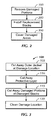
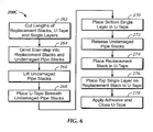
Figures 2 through 7 show multiple flow charts of procedures to repair a flexible pipe in accordance with one or more embodiments of the present disclosure. -
Figure 8 shows a schematic cross-sectional view of a repaired pipe in accordance with one or more embodiments of the present disclosure. -
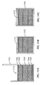
Figures 9A-9C show schematic cross-sectional views of a composite flexible pipe in accordance with one or more embodiments of the present disclosure. -
Figures 10A-10C show schematic cross-sectional views of a composite flexible pipe in accordance with one or more embodiments of the present disclosure. -
Figures 11A-11C show schematic cross-sectional views of a composite flexible pipe in accordance with one or more embodiments of the present disclosure. -
Figures 12A-12C show schematic cross-sectional views of a composite flexible pipe in accordance with one or more embodiments of the present disclosure. - A flexible pipe and a method of repairing the same, according to embodiments of the present disclosure, will be explained hereinafter by referring to the accompanying drawings.
- The present disclosure may comprise a repair method for composite pipe similar to that disclosed in
U.S. Patent Number 6,491,779, filed on April 24, 2000 , entitled "Method of Forming a Composite Tubular Assembly,"U.S. Patent No. 6,804,942, filed on September 27, 2002 , entitled "Composite Tubular Assembly and Method of Forming Same," andU.S. Patent No. 7,254,933, filed on May 6, 2005 , entitled "Anti-collapse System and Method of Manufacture,". The method may also be suitable for repairing any bonded or unbonded flexible pipe structure that employs composite materials for hoop reinforcement and/or tensile reinforcement. - During installation and in service, damage may occur to the exterior of flexible pipes. Often this damage may be to hoop or tensile reinforcement layers beneath an outer jacket. One or more embodiments of the present disclosure are related to repair procedures directed to repair the hoop or tensile reinforcement layers of a composite flexible pipe in-situ, thereby reducing the amount of time a rig may be delayed from production and/or operation.
- Referring initially to
Figure 1 , an isometric view of a compositeflexible pipe 10 is shown. Apipe structure 12 may be helically wrapped with a first layer ofcomposite tape stacks 14 in a first orientation and a second layer ofcomposite tape stacks 16 which may be counter wound with respect to stacks 14 in an opposite orientation. Ananti-abrasive layer 18 may be disposed betweenstacks 14 and stacks 16 and ajacket 20 may cover the layers of thepipe 10 to provide external protection. AlthoughFigure 1 depicts a relatively simplecomposite pipe structure 10, those skilled in the art will appreciate that acomposite pipe 10 may include additional and/or different layers, including liners, hoop-stress reinforcement layers, anti-wear layers, lubricating layers, tensile reinforcement layers, anti-extrusion layers, membranes, and/or any other layers as may be included in a composite flexible fiber-reinforced pipe. - The stack layers 102 and 104 may comprise helically wrapped stacks of laminated material. The stacks may be made of non-metallic fiber-reinforced tapes that may be laminated and bonded together as a single structural member. The individual layers of the stacks may include UD (unidirectional) tape or other structural and/or reinforced tape.
- The repair methods as described in embodiments of the present disclosure may be performed when an outer jacket and one or more layers of helically wrapped stacks that may include the hoop and/or tensile reinforcement layers are damaged.
- Generally, referring to
Figure 2 , embodiments of the present disclosure may include a process of removing damagedstacks 100, a process of installingreplacement stacks 200, and a process of sealing and/or covering the damagedarea 300. If performing the repair in-situ, any or all operational or installation loads may be removed from the damaged section of pipe, which may include pressure loads, bending loads, tension loads, torque loads, and/or any other loads that may be acting on the damaged area of pipe. Furthermore, the composite pipe may be stabilized and any stored energy may be released and/or controlled, and the pipe may be removed from service and all valves and flow prevention devices and/or methods may be activated. - Reference may be made to the following terms throughout the present disclosure. A tape stack refers to stacks of composite material that may be attached to a pipe and may form the pipe structure. As noted, a tape stack may include one or more non-metallic fiber-reinforced tapes. Undamaged stack refers to tape stacks that are still attached to the pipe but have not been damaged. Undamaged stacks may include tape stacks that have a damage portion removed therefrom. A damaged stack refers to a portion of the tape stack that may have suffered damage. A replacement stack refers to a stack of composite material the same as or similar to the composition of the tape stack. The replacement stack may be a partial length of tape stack. Barrier tape may be a tape that may allow for relative movement between layers that may be on each side of the barrier tape layer. Barrier tape may also provide protection to surfaces to which it may be applied.
- Further, U-tape may be made of the same tape as that barrier tape, or may be a different tape such as a "Z" shaped, or "Z-tape" used in the manufacture of composite flexible pipe. The U-tape may not have a "U" shape as manufactured, but may be manipulated into forming a "U" shape. Accordingly, the U-tape may be provided from a roll or sheets of tape and then manipulated during installation into a "U" shape. A single strip may be a single strip of the material which makes up the tape stacks or replacement stacks, such as a strip of UD tape or other fiber-reinforced non-metallic tape strip. As described above, the tape stacks and replacement stacks may be made of multiple layers which may be similar to the single strip. A protective layer may be a tape layer or an applied paste, gel, or other material which may provide a sealing layer and/or a binding layer or may be made from the barrier tape. A jacket may be made from extruded material, and the replacement jacket may be a portion of a jacket. The replacement jacket may be welded to the undamaged outer jacket of the pipe. The replacement jacket may also be a helical tape wrap applied externally to the undamaged jacket, covering the damaged section. The replacement jacket may also be a heat shrink tube or heat shrink wrap applied externally to the undamaged jacket, covering the damaged section. A protective exterior wrap may be a tape layer applied to the surface of the pipe or may be shrink-wrap and/or self-adhering tape, such as ethylene propylene copolymer tape. Adhesives may be epoxies, epoxy resins, and/or other binding agents and/or materials known in the art.
- Referring now to
Figure 3 , an exemplary process to removedamaged stacks 100 in accordance with one or more embodiments of the present disclosure will be described. Specifically, an outer jacket that may be damaged may be removed atstep 105. To remove an appropriate amount of jacket around the damage location a strap may be applied to the surface of the pipe above and/or below the area to be removed. The strap may be used to serve as a guide for marking and cutting throughout the repair. Chalk, wax pencil, or other suitable markings may be made to the exterior of the pipe to outline or demark the desired area for repair. To remove the outer jacket a hot knife may be used to cut through the material of the outer jacket. Alternatively, a circular saw, utility knives, or other cutting instruments may be used to cut away the damaged area of the outer jacket. When cutting into the jacket, it may be desired that the cuts do not cut too deep and do not impact a first layer under the jacket. After removal of any damaged portions of the jacket a jacket window may be formed. The jacket window may be defined by the edge of the undamaged jacket that remains surrounding the damaged area of the pipe. The jacket window may allow access to damaged layers of the pipe. Further, an edge of the jacket window may be a distance away from the damaged stacks. The distance may be such as to allow for some manipulation of the undamaged portions of the tape stacks (i.e., undamaged stacks). - Next, at
step 110, a protective layer that may be the first layer beneath the jacket may be removed from around the damaged location. The outer layer may be an anti-torque layer which may include binding tape, such as Z-tape used in the manufacture of composite flexible pipe. A border of this layer may remain, so that an edge of the layer may be exposed within the jacket window. For example, a 2.54cm (one inch) border may remain visible and covering and protecting undamaged stacks in the jacket window. However, those skilled in the art will appreciate that the amount of exposed outer layer may vary, and may even be completely removed from the jacket window,. - In
step 115, the damaged portions of the tape stacks (i.e., the damaged stacks) may be removed. In certain embodiments, only the portion which is damaged may be removed, so that what remains may be partial sections of exposed portions of the stacks that remain directly attached to the pipe (i,e., the undamaged stacks). A cutting tool may be used to remove the damaged stacks. The cutting tool may be a circular saw, a rotary cutting wheel, or any other cutting tool known in the art that may cut through the tape stacks. In certain embodiments, when removing the damaged stacks, 10.16 cm (4") or more of undamaged stacks may be left visible within the jacket window to be manipulated. Furthermore, the cuts of adjacent damaged stacks may be made with some amount of separation or linear distance along the length of the tape stacks between where the cuts are made. Those skilled in the art will appreciate that the length of exposed tape stacks may vary to be longer or shorter than 10.16 cm (4"). - Finally, in
step 120, the damage location, following removal of the damaged stacks, may be cleaned. The damage location may be cleaned with a solvent, clean compressed air, alcohol wipes, and/or any other cleaning agent or device that may remove dust and other particles and prepare the damage location for the repair. The damage location may also be dried with a moisture absorbing cloth, forced air convection (with or without heated air), or other drying means known in the art. - Referring now to
Figure 4 , one or more embodiments of the present disclosure with respect to the installation of the replacement stacks will be described. In the exemplary embodiment detailed inFigure 4 , the process of installingreplacement stacks 200A will be described. - In a
first step 202, lengths of replacement stacks may be cut to size. Each damaged stack that may be removed may have a custom replacement stack cut to fit. Accordingly, the replacement stacks may fit into a void created by the removed damaged stacks. Further, lengths of U-tape may be cut. The U-tape may be a flat tape which may have a linear length, which may be a length along the length of a tape stack and a width which may be a width designed to wrap around a repaired tape stack. Each replacement stack may have one section of U-tape cut to size. The linear (i.e., axial) length of the U-tape may extend longer than the replacement stacks to which they may correspond. For example, the U-tape for a particular replacement stack may be about 20.32 cm (8") longer than the replacement stack it may correspond to. Additionally, lengths of single strips may be cut the same length as the U-tape. Each replacement stack may have two corresponding single strips. Those skilled in the art will appreciate that the length of the U-tape and single strips may vary. Further, the U-tape and the single strips may be of different lengths, such that one may be longer than the other in length along the stack. - Next, in
step 204, all contact surfaces may be abraded to allow for a clean bonding between different elements during the repair procedure. The contact surfaces may include the surfaces of the U-tape, both sides of the single strips, all sides of the replacement stacks, and surfaces of the undamaged stacks. The abrasion may be made by a physical or chemical process. Physical abrasion may be accomplished by sanding, grinding, filing, or other physical abrasion tools or methods. Chemical abrasion may be accomplished by chemicals which may etch the surface of the composite material. After abrasion, the damage location may be cleaned, as describe above, which may allow for clean contact surfaces for binding during the repair process. - Next, in
step 206, the undamaged stacks may be lifted to expose the undamaged portion of pipe beneath. The length of undamaged stack to be lifted may correspond to the additional length of the U-tape beyond the length of its corresponding replacement stack. The additional length may be a distance of overlap that the U-tape and the single strips may have with the undamaged stacks. For example, as described above, a U-tape may be cut to be 20.32 cm (8") longer than a corresponding replacement stack, accordingly, each side of the undamaged stacks may be lifted at least 10,16 cm (4") to accommodate the full length of the U-tape, and thereby creating a distance of overlap of 10.16 cm (4") for each side of the undamaged stack. Accordingly, instep 208, the U-tape may be placed beneath the lifted undamaged stacks. A distance of overlap for each end of the exposed undamaged stack may exist due to the extended length of the U-tape. - Next, in
step 210, a first single strip may be placed within the U-tape, beneath the lifted undamaged stack and parallel to the direction of the tape stack. Adhesive may be applied between the first single strip and the U-tape into which it may be placed. Accordingly, a bond may be formed between the first single strip and the U-tape. - In
step 212, the undamaged stacks may be released. Adhesive may be applied to the under side of the undamaged stacks and/or the first single strip so that a bond may be formed between the first single strip and the undamaged stacks. - Next, in
step 214, a replacement stack may be placed on the first single strip within the U-tape and between the ends of the undamaged stacks defining a void representing the removed damaged stack. Adhesive may be applied between the first single strip and the replacement stack so that a bond may be formed between the two elements. The replacement stack may be placed in the center of the U-tape so that a continuous section of repaired tape stack may be formed which may include the disconnected undamaged stacks and the replacement stack placed therebetween. - In step 216 a second single strip may be placed on the surface of the replacement stack and may extend over the surface of the undamaged stack for the distance of overlap. Adhesive may be applied between these layers so that a bond may be formed therebetween. The second single strip may be placed so that the additional length may extend in either direction for the length of the overlap.
- Finally, in
step 218, the U-tape may be folded over and/or closed so that a single continuous repaired tape stack may be formed. Adhesive may be applied to the inner surface of the U-tape and/or the top surface of the second single strip, thereby forming a bond between the layers. -
Steps 202 through 218 may be repeated for each damaged stack. - A cross-sectional view of a repaired tape stack in accordance with embodiments of the present disclosure, and particularly
process 200A, is shown inFigures 8 ,9A-9C , and12A-12C , which will be described below. - An alternative exemplary process in accordance with one or more embodiments of the present disclosure will now be discussed with reference to
Figure 5 andrepair process 200B, directed to installing the replacement stacks. - In a
first step 232, similar to step 202 ofprocess 200A, replacement stacks may be cut to size. Additionally, U-tape and single strips may be cut to size for each replacement stack. The U-tape and the single strips may be cut for a distance of overlap, similar to that described above. Further, the U-tape and single strips may be the same or different lengths. - In
step 234, a replacement assembly may be assembled (seeFigure 12A ). The surfaces of the replacement stack may be abraded. Further, surfaces of the single strips may be abraded. The replacement assembly may be constructed by applying an adhesive to the abraded surfaces of the replacement stack and a contact surface of the single strips. A single strip may be applied to the top and the bottom of the replacement stack, thereby forming a substantially "I" shape, in which the replacement stack may be a central body and the two single strips may extend for the distance of overlap in each direction. - In
step 236, the undamaged stacks may be lifted to expose the undamaged portion of pipe as described above instep 208 ofprocess 200A. - Next, in
step 238, the U-tape may be placed beneath the lifted undamaged stack, so that the distance of overlap of the U-tape may extend under each exposed end of the undamaged stack. - In
step 240, the replacement assembly constructed instep 234 may be placed in the U-tape. An adhesive may be applied to the bottom of the replacement assembly and/or the U-tape so that a bond may be formed between the two. - Next, in
step 242, each end of the top single strip of the replacement assembly may be lifted so that the undamaged stacks may be released, in step 244 (seeFigure 12B ). Then, instep 246, each end of the lifted top single strip may be released, thereby creating a continuous length of repaired tape stack, which may include the replacement assembly and the undamaged stacks (seeFigure 12C ). Further, adhesive may be applied between the single strips and the lifted portions of the undamaged stack to form a bond therebetween. - Finally, in
step 248, adhesive may be applied to the U-tape, and it may be sealed, to thereby create the repaired tape stack. - Steps 232-248 may be repeated for each damaged stack.
- A cross-sectional view of a repaired tape stack in accordance with embodiments of the present disclosure, and particularly
process 200B, is shown inFigures 8 and9A-9C , which will be described below. - An alternative exemplary process in accordance with one or more embodiments of the present disclosure will now be discussed with reference to
Figure 6 andrepair process 200C, directed to installing the replacement stacks. - In a
first step 262, lengths of replacement stacks may be cut to size. Each damaged stack that may be removed may have a custom replacement stack cut to fit. The replacement stacks may be cut to a length that extends farther than the void created by the removed damaged stacks. For example, the length of the replacement stacks may be cut to be 20.32 cm (8 ") longer than the void created by removal of the damaged stacks. However, those skilled in the art will appreciate that the additional length of the replacement stacks as compared to the void may be varied, and particularly is not limited to additional 20.32 cm (8"). Further, lengths of U-tape and single strips may be cut, as described above with respect to step 202 ofprocess 200A. The lengths of U-tape and single strips may be longer than the length of the replacement stacks. - Next, in
step 264, the undamaged stacks and the replacement stacks may be grinded to form stair-step engagement surfaces, as shown inFigures 1OB and 1OC . Accordingly, the surface of contact between the replacement stack and the undamaged stacks may be increased, which may allow for a stronger bond between the replacement stacks and the undamaged stacks. The replacement stacks may be grinded to match the stair-step pattern of the corresponding undamaged stacks, which may optimize the contact surfaces. The grinding may be made with a suitable grinding tool, which may grind through layers of the tape stacks. - Further, all contact surfaces may be abraded, which may allow for a secure bonding between different elements during the repair procedure. The contact surfaces may include the surfaces of the U-tape, both sides of the single strips, all sides of the replacement stacks, and surfaces of the undamaged stacks including the stair-step portions. The abrasion may be made my physical or chemical means. After abrasion, the damage location may be cleaned, as describe above, which may allow for clean contact surfaces for binding during the repair process.
- Next, in
step 266, the undamaged stacks may be lifted to expose the undamaged portion of pipe beneath. The length of undamaged stack to be lifted may correspond to the additional length of the U-tape beyond the length of its corresponding replacement stack. The additional length may be a distance of overlap that the U-tape may have with the undamaged stacks, as described above. - Next, in
step 268, the U-tape may be placed beneath the lifted undamaged stacks, and may cover the distance over overlap. - Next, in
step 270, a first single strip may be placed within the U-tape, beneath the lifted undamaged stack. Adhesive may be applied between the first single strip and the U-tape into which it may be placed. Accordingly, a bond may be formed between the first single strip and the U-tape. - In
step 272, the undamaged stacks may be released. Adhesive may be applied to the under side of the undamaged stacks and/or the first single strip so that a bond may be formed between the first single strip and the undamaged stacks. - Next, in
step 274, a replacement stack may be placed on the first single strip within the U-tape and between the ends of the undamaged stacks defining an area representing the removed damaged stack. The stair-step surfaces may contact. Adhesive may be applied between the first single strip and the replacement stack so that a bond may be formed between the two elements. The replacement stack may be placed in the center of the U-tape so that a continuous section of repaired tape stack may be formed which may include the disconnected undamaged stacks and the replacement stack placed therebetween. Further, adhesive may be applied between the undamaged stacks and the replacement stack, so that all of the surfaces of the stair-step may be bonded to each other. - In step 276 a second single strip may be placed on the surface of the replacement stack and may extend over the surface of the undamaged stack for the distance of overlap. Adhesive may be applied between these layers so that a bond may be formed therebetween. The second single strip may be placed so that the additional length may extend in either direction for the length of the overlap.
- Finally, in
step 278, the U-tape may be folded over and/or closed so that a single continuous repaired tape stack may be formed. Adhesive may be applied to the inner surface of the U-tape and/or the top surface of the second single strip, thereby forming a bond between the layers. - A cross-sectional view of a repaired tape stack in accordance with embodiments of the present disclosure, and particularly
process 200C, is shown inFigures 10A-10C , which will be described below. - Further, with respect to
exemplary processes procedure 200B may be assembled in advance, as well, if the dimensions are known in advance. In one or more embodiments of the present disclosure, replacement stacks and/or outer jacket repair material may be taken from a section of pipe that was manufactured to the same dimensional and material requirements as the pipe that may be repaired. - The procedure of covering of the repaired
damage location 300 will now be described with reference toFigure 7 . In step 305 a replacement jacket may be cut to fit the exposed surface of the damage location, which may fit to the jacket window. This may be performed in advance if the dimensions are known prior to arrival at the damage location or at any time during the repair process. Alternatively, the damaged jacket may be used as a template to cut the replacement jacket, if available. - In
step 310, a protective layer may be placed and/or sealed over the repaired damage location. The protective layer may be made of barrier tape. - In
step 315, the replacement jacket may be placed over the repaired damage location. The replacement jacket may be placed in the jacket window for installation. Further, the replacement jacket may be compressed into the jacket window. The compression may be accomplished by use of a ratcheting mechanism on tie-down straps or other compressive means known in the art. - Once held in place, the jacket may be sealed to the pipe in
step 320. The seal may be made by a weld, extruded material, and/or other sealing method or means. Specifically, the seams that may exist between the replacement jacket and the jacket window may be sealed. The welding may be done by a hot knife, a heat gun, torch, thermoplastic welder, or any other tool which may allow for plastic welding. After welding, the weld may be allowed to cool. When cooling, active quenching may be avoided. The extrusion may be made by an extruding gun, which may extrude plastic feedstock or other plastic or sealing material. The compression tie-down straps may then be removed. Any remaining unsealed seams may then be sealed. The compressive tie-down straps may then be reapplied to the repaired damage location to compress the jacket and stack assembly. - Finally, in
step 325, a protective exterior wrap may be applied around the repaired damage location. The compressive tie-down straps may be removed prior to applying the protective exterior wrap. Further, after the protective exterior wrap may be applied, the tie-down straps may be re-installed to apply compression to the wrap, the jacket, and the stack assembly. - Now referring to
Figure 8 , a cross-sectional schematic of an exemplary completed repair, in accordance with one or more embodiments of the present disclosure, will be described (not shown to scale). A repairedtape stack 800 may be repaired in accordance with one or more embodiments of the present disclosure. Accordingly, a section of anundamaged pipe 801 may form the base of the repaired section.Undamaged pipe 801 may include multiple layers of a composite flexible pipe, as described above. -
U-tape 802 may be the first layer in contact with the surface ofundamaged pipe 801. Next, a firstsingle strip 803 may be located on top ofU-tape 802. In contact with firstsingle strip 803 may be replacement stacks 804 and sections ofundamaged stacks 805. As noted above, a distance ofoverlap overlap single strip 803 may be omitted. - Above replacement stacks 804 and
undamaged stacks 805, a secondsingle strip 806 may be applied. Above secondsingle strip 806,U-tape 802 may be folded and/or sealed over thereplacement stack 804, theundamaged stacks 805, andsingle strips protective layer 807 may be applied over the stack assembly to seal the replacement stacks within the pipe. - A
replacement jacket 808 may then cover the replacement stacks and the repaired region. Finally, a protectiveexterior wrap 809 may be applied to the surface of the pipe at the damage location to further seal and protect the repaired damage location. - Adhesive may be applied between each layer. Application of the adhesive may be preceded by abrading the surface to which the adhesive may be applied. The abrasion may be either chemical or physical abrasion.
- Now referring to
Figures 9A-9C , a cross-sectional schematic of the repair process in accordance with one or more embodiments of the present disclosure is shown. Particularly,Figures 9A-9C may schematically represent a cross-sectional view of the repair process in accordance withprocesses -
Figure 9A shows a schematic of a damagedstack 900, withstacks 920. Only a damaged stack is shown, and other layers of the pipe are omitted from the schematic.Stacks 920 may have a damagedsection 921, which may include damage to multiple layers of the tape stacks 920. -
Figure 9B shows a representation of thetape stack 900 during the repair process. Specifically,undamaged stacks 905 may define a region of damagedstack 922.Damaged stack 922 may be removed by processes according to one or more embodiments of the present disclosure. -
Figure 9C shows thetape stack 900 as repaired in accordance with one or more embodiments of the present disclosure. Specifically,undamaged stacks 905 andreplacement stack 904 may define a continuous length of repairedtape stack 900. The repairedtape stack 900 may be bounded and supported by a firstsingle strip 903 and a secondsingle strip 906. Further, as shown,single strips overlap - Now referring to
Figures 10A-10C , a cross-sectional schematic of the repair process in accordance with one or more embodiments of the present disclosure is shown. Particularly,Figures 10A-10C may schematically represent a cross-sectional view of the repair process in accordance withprocess 200C. -
Figure 10A shows a schematic of atape stack 1000, includingstacks 1020 with a damagedsection 1021, similar to that shown inFigure 9A . -
Figure 10B shows a representation of thetape stack 1000 during the repair process. Specifically,undamaged stacks 1005 may define a section of damagedstack 1022.Damaged stack 1022 may be removed by processes according to one or more embodiments of the present disclosure. Also shown inFigure 10B is the stair-step ofundamaged stacks 1005. -
Figure 10C shows a repairedtape stack 1000 in accordance with one or more embodiments of the present disclosure. Specifically,undamaged stacks 1005 andreplacement stack 1004 may define a continuous length of repairedtape stack 1000. The repairedtape stack 1000 may be bounded and supported by a firstsingle strip 1003 and a secondsingle strip 1006. Further, as shown,single strips overlap Figure 10C is the stair-step ofreplacement stack 1004, which may contact the stair-step ofundamaged stacks 1005. - Now referring to
Figures 11A-11C , a cross-sectional schematic of the repair process in accordance with one or more embodiments of the present disclosure is shown. Particularly,Figures 11A-11C may schematically represent a cross-sectional view of the repair process as viewed along the length of the tapes. Particularly,Figures 11A-11C show the U-tape as applied. -
Figure 11A shows areplacement stack 1115 including a bottomsingle strip 1103,replacement stack 1104, and a topsingle strip 1106. The replacement stack is placed within a U-shaped tape, 1102. -
Figure 11B shows the U-tape 1102 sealed in accordance with one or more embodiments of the present disclosure. Particularly, U-tape 1102 may be wrapped aroundreplacement stack 1115. U-tape 1115 may be cut to length so that there is minimal increase in the height of thereplacement stack 1115. In contrast, inFigure 11C , U-tape 1102 may be fully wrapped, so as to maximize the contact surfaces. However, as shown in Figure HC, the height of the replacement stack may be increased. Furthermore, those skilled in the art will appreciate that other lengths of overlap and height increase may be achieved. - Now referring to
Figures 12A-12C , a cross-sectional schematic of the repair process in accordance with one or more embodiments of the present disclosure is shown. Particularly,Figures 12A-12C may schematically represent a cross-sectional view of the repair process in accordance withprocess 200B. -
Figure 12A shows a cross-section of areplacement assembly 1200, which may includereplacement stacks 1204, a topsingle strip 1206, and a bottomsingle strip 1203.Replacement stacks 1204, topsingle strip 1206, and bottomsingle strip 1203 may be bonded together with epoxy prior to installation. -
Figure 12B shows both ends of topsingle strip 1206 lifted to allow forundamaged stacks 1205 to be placed in contact with (and bonded to) bottomsingle strip 1203 and replacement stacks 1204.Figure 12C shows the completed repaired stack with topsingle strip 1206 bonded to the top ofundamaged stacks 1205. - The foregoing outlines feature several embodiments so that those skilled in the art may better understand the aspects of the present disclosure. Those skilled in the art will appreciate that they may readily use the present disclosure as a basis for designing or modifying other processes and structures for carrying out the same purposes and/or achieving the same advantages of the embodiments introduced herein. Those skilled in the art should also realize that such equivalent constructions do not depart from the spirit and scope of the present disclosure, and that they may make various changes, substitutions and alterations herein without departing from the spirit and scope of the present disclosure.
- Advantageously, embodiments disclosed herein allow for in-situ repair of composite pipe, whereas damaged composite pipe previously would have to be completely replaced and damaged metallic pipe could advantageously have been weld-repaired. Accordingly, embodiments disclosed herein allow certain kinds of composite pipe (e.g., composite pipe made of tape stacks) to be closer to equal level with metallic pipe in terms of reparability, thus allowing more widespread adoption of such composite pipe manufactured from of helically-wrapped stacks of laminated strips of material.
- Advantageously, a repair performed in accordance with one or more embodiments disclosed herein may be performed in-situ. Further, the down time of a rig may be reduced substantially by the ability to perform the disclosed procedures in- situ with readily available tools and parts.
- Advantageously, as at most two single strips may be added to the tape stack during the repair process, there may only be a slight increase in the diameter of the pipe at the damaged location. The small increase may allow for the pipe to function as if it was undamaged, and may allow for smooth and continuous pipe sections that may be as strong as or stronger than the original undamaged pipe. Further, a binding material, such as epoxy, may be used, and additional single strips may be added, along with a large surface area of contact between the replacement stack and the undamaged stack, the strength of the composite pipe may be as strong as or stronger than the original undamaged pipe.
- While the disclosure has been presented with respect to a limited number of embodiments, those skilled in the art, having benefit of this disclosure, will appreciate that other embodiments may be devised within the scope of the claims.
Claims (15)
- A method to repair flexible fiber-reinforced pipe comprising a plurality of helically-wrapped stacks of laminated strips of material, the method comprising:removing a portion of existing stacks (100) from a damage location (300);applying an adhesive to a surface of replacement stacks (200; 200A; 804; 1004; 1115; 1204);installing the replacement stacks (200; 200A; 804; 1004; 1115; 1204) to the damage location (300); andbinding the replacement stacks (200; 200A; 804; 1004; 1115; 1204) to remaining existing stacks with the applied adhesive.
- The method of claim 1, further comprising:installing a replacement jacket (808) over the replacement stacks (804).
- The method of claim 1, further comprising:installing a first single strip (1003) of material below the replacement stacks (804; 1004; 1204), wherein the length of the first single strip (803; 1003; 1206) of material extends to a first distance of overlap (810; 1010); andinstalling a second single strip (806; 1006; 1206) of material above the replacement stacks (804; 1004; 1204), wherein the length of the second single strip (804; 1006; 1206) of material extends a second distance of overlap (811; 1011).
- The method of claim 3, wherein installing replacement stacks (804; 1115) comprises:disposing U-Tape (802; 1102) below the undamaged portions and covering the damage location for a width of one stack;and sealing the U-Tape (1102) around the first single strip of material, the replacement stack, and the second single strip of material.
- The method of claim 4, further comprising:abrading surfaces of contact of at least one of the U-Tape, the first single strip of material, the second single strip of material, and the replacement stack; andapplying an adhesive to one or more of the abraded surfaces to allow for binding between the contact surfaces.
- The method of claim 1, further comprising:grinding at least one exposed end of the existing stacks to form a stair-step surface; andgrinding at least one end of the replacement stack to form a corresponding stair-step surface to correspond with the stair-step surface of the existing stacks.
- The method of claim 1, further comprising:cutting away an exterior jacket of the pipe around the damage location;removing sections of damaged stacks from the damage location;abrading an exposed surface of the damage location; installing cover U-Tape in the damage location; laying the replacement stacks in the cover U-Tape; andclosing the cover U-Tape over the replacements stacks.
- The method of claim 2, wherein the installing the replacement jacket comprises plastic welding the replacement jacket to a surface of the pipe.
- The method of claim 2, wherein the installing the replacement jacket comprises extruding a plastic material to seal the replacement jacket to a surface of the pipe.
- The method of claim 1, further comprising covering the pipe around the damage location with a protective layer.
- The method of claim 1, wherein the installing replacement strips comprises:bending and securing undamaged stacks of the pipe away from the damage location;applying epoxy to the replacement stacks to undersides of the bent undamaged stacks;releasing the bent undamaged stacks; andapplying epoxy to the replacement stacks to upper sides of the released undamaged stacks.
- The method of claim 1, further comprising: removing at least one of tensile loads, compression loads, and internal pressure loads from the pipe prior to performing the repair.
- The method of claim 1, further comprising applying a barrier tape to undamaged stacks exposed by the removed damaged portions of the damaged stacks prior to installing the replacement stacks.
- The method of claim 2, further comprising applying a barrier material to the installed replacement stacks prior to installing the replacement jacket.
- The method of claim 1, wherein the replacement stacks comprise protective tape wrapped there around.
Applications Claiming Priority (2)
| Application Number | Priority Date | Filing Date | Title |
|---|---|---|---|
| US15937309P | 2009-03-11 | 2009-03-11 | |
| PCT/US2010/026812 WO2010104941A2 (en) | 2009-03-11 | 2010-03-10 | Method and apparatus to repair flexible fiber-reinforced pipe |
Publications (3)
| Publication Number | Publication Date |
|---|---|
| EP2406532A2 EP2406532A2 (en) | 2012-01-18 |
| EP2406532A4 EP2406532A4 (en) | 2013-07-17 |
| EP2406532B1 true EP2406532B1 (en) | 2015-05-20 |
Family
ID=42729073
Family Applications (1)
| Application Number | Title | Priority Date | Filing Date |
|---|---|---|---|
| EP20100751348 Not-in-force EP2406532B1 (en) | 2009-03-11 | 2010-03-10 | Method to repair flexible fiber-reinforced pipe |
Country Status (8)
| Country | Link |
|---|---|
| US (1) | US8617331B2 (en) |
| EP (1) | EP2406532B1 (en) |
| CN (1) | CN102422068A (en) |
| AU (1) | AU2010224241B2 (en) |
| BR (1) | BRPI1008966A2 (en) |
| MY (1) | MY156836A (en) |
| WO (1) | WO2010104941A2 (en) |
| ZA (1) | ZA201107174B (en) |
Families Citing this family (5)
| Publication number | Priority date | Publication date | Assignee | Title |
|---|---|---|---|---|
| EP2707635A4 (en) * | 2011-05-13 | 2014-11-12 | Deepflex Inc | Reinforcement laminate having an alignment feature |
| CN104790683B (en) * | 2015-04-14 | 2017-11-10 | 同济大学 | A kind of method using Building Strengthened by FRP Sheets metal pipe node |
| US11577479B2 (en) | 2018-07-30 | 2023-02-14 | The Boeing Company | Locking hole plug for sealing holes in composite structures |
| US10844990B1 (en) * | 2020-02-28 | 2020-11-24 | Trinity Bay Equipment Holdings, LLC | Repair system and method |
| US11199287B1 (en) * | 2021-02-23 | 2021-12-14 | Trinity Bay Equipment Holdings, LLC | Multi-layer pipe tubing repair systems and methods |
Family Cites Families (18)
| Publication number | Priority date | Publication date | Assignee | Title |
|---|---|---|---|---|
| CN2327865Y (en) * | 1998-04-22 | 1999-07-07 | 王明岐 | Structure for repairing and connecting steel pipe with turnable glass fiber reinforced plastic lining |
| JP2000055289A (en) | 1998-08-10 | 2000-02-22 | Sanken:Kk | Repair material for the connection between the bottom of the manhole and the pipeline |
| JP3790052B2 (en) * | 1998-09-25 | 2006-06-28 | 株式会社湘南合成樹脂製作所 | Manufacturing method of pipe lining material |
| US6174392B1 (en) * | 1999-03-04 | 2001-01-16 | Northrop Grumman Corporation | Composite structure repair process |
| US6491779B1 (en) | 1999-05-03 | 2002-12-10 | Deepsea Flexibles, Inc. | Method of forming a composite tubular assembly |
| JP3951289B2 (en) | 2001-10-05 | 2007-08-01 | 東海ゴム工業株式会社 | Non-permeable composite hose |
| JP4464852B2 (en) * | 2005-03-14 | 2010-05-19 | オリンパス株式会社 | Endoscope and endoscope repair method |
| US20060272724A1 (en) | 2005-04-26 | 2006-12-07 | Borland Robin N | System and method for pipe repair using fiber wrap and polymeric resin |
| US7254933B2 (en) | 2005-05-06 | 2007-08-14 | Deepflex Inc. | Anti-collapse system and method of manufacture |
| US7513275B2 (en) * | 2005-12-01 | 2009-04-07 | Neptune Research, Inc. | Repair kit for natural gas pipe |
| JP4512839B2 (en) | 2006-07-25 | 2010-07-28 | 株式会社ニチリン | Manufacturing method of protector-coated bent hose |
| JP4916301B2 (en) | 2006-12-25 | 2012-04-11 | 芦森工業株式会社 | Hose repair method |
| US8218852B2 (en) * | 2007-05-08 | 2012-07-10 | Spirit Aerosystems, Inc. | System and method for repairing composite parts |
| JP5025340B2 (en) | 2007-06-14 | 2012-09-12 | 芦森工業株式会社 | Hose repair patch and hose repair method |
| US20090054406A1 (en) | 2007-08-21 | 2009-02-26 | Ward Keith W | Compositions and Methods for Modulating Endophthalmitis Using Fluoroquinolones |
| US7628879B2 (en) * | 2007-08-23 | 2009-12-08 | The Boeing Company | Conductive scrim embedded structural adhesive films |
| US7938146B2 (en) * | 2008-02-08 | 2011-05-10 | Western Specialties, Llc | Repair apparatus and method for pipe and fittings |
| FR2949092B1 (en) | 2009-08-12 | 2011-10-28 | Jedo Technologies | METHOD FOR REPAIRING A WALL CONSISTING OF MULTIPLE LAYERS |
-
2010
- 2010-03-10 BR BRPI1008966A patent/BRPI1008966A2/en not_active IP Right Cessation
- 2010-03-10 MY MYPI2011004222A patent/MY156836A/en unknown
- 2010-03-10 CN CN2010800204066A patent/CN102422068A/en active Pending
- 2010-03-10 AU AU2010224241A patent/AU2010224241B2/en not_active Ceased
- 2010-03-10 WO PCT/US2010/026812 patent/WO2010104941A2/en not_active Ceased
- 2010-03-10 US US13/255,702 patent/US8617331B2/en not_active Expired - Fee Related
- 2010-03-10 EP EP20100751348 patent/EP2406532B1/en not_active Not-in-force
-
2011
- 2011-09-30 ZA ZA2011/07174A patent/ZA201107174B/en unknown
Also Published As
| Publication number | Publication date |
|---|---|
| CN102422068A (en) | 2012-04-18 |
| MY156836A (en) | 2016-03-31 |
| AU2010224241B2 (en) | 2014-03-27 |
| WO2010104941A2 (en) | 2010-09-16 |
| AU2010224241A1 (en) | 2011-10-13 |
| ZA201107174B (en) | 2012-06-27 |
| WO2010104941A3 (en) | 2011-01-13 |
| EP2406532A2 (en) | 2012-01-18 |
| US20120000596A1 (en) | 2012-01-05 |
| US8617331B2 (en) | 2013-12-31 |
| BRPI1008966A2 (en) | 2016-03-15 |
| EP2406532A4 (en) | 2013-07-17 |
Similar Documents
| Publication | Publication Date | Title |
|---|---|---|
| US8617331B2 (en) | Method and apparatus to repair flexible fiber-reinforced pipe | |
| US8522827B2 (en) | Protective seal for pipeline assembly | |
| CA2688093C (en) | Method for manufacturing an object from a sandwich structure having a reinforced corner and an object of this type | |
| CN101370643B (en) | Method of making composite panels with U-shaped stiffeners | |
| US20160263775A1 (en) | Wind Turbine Blades | |
| JP2010536024A (en) | Composite laminated structure | |
| US20220073317A1 (en) | Seal For A Vacuum Material Lifter | |
| EP2137450A1 (en) | Flexible composite tubular assembly with high insulation properties and method for making same | |
| JP2014532000A (en) | Lightweight flexible mandrel and method of making a lightweight flexible mandrel | |
| KR101872737B1 (en) | Manufacturing method for anisogrid composite structure without outer cover | |
| JP5260735B2 (en) | Integrated tire repair | |
| CN109789650A (en) | Method of repairing composite stringers with composite repair caps | |
| US20110281044A1 (en) | Composite structures with unidirectional fibers | |
| JP2012251591A (en) | Regeneration pipeline, and method for regenerating pipeline | |
| EP2317203B1 (en) | Method for coating a joint between two pipes | |
| CN102893069A (en) | Helically corrugated synthetic resin pipe with joint, and structure for connecting helically corrugated synthetic resin pipes | |
| JP4881845B2 (en) | Seismic retrofitting method for existing pipe manhole connections | |
| US20160167317A1 (en) | Secondary groove for work piece retention during machining | |
| JP4362751B2 (en) | Cold storage structure for cryogenic fluid transport piping | |
| JP2019181798A (en) | Pipe manufacturing method and seam member | |
| JP3253746B2 (en) | Manufacturing method of high pressure rubber hose | |
| JP4110148B2 (en) | Road surface treatment method and traveling type tape sticking device | |
| CN215478756U (en) | Wound repairing belt convenient to cut and use | |
| JP4488752B2 (en) | Buried object protection device | |
| CA3239388A1 (en) | A method and apparatus for joining hollow structures |
Legal Events
| Date | Code | Title | Description |
|---|---|---|---|
| PUAI | Public reference made under article 153(3) epc to a published international application that has entered the european phase |
Free format text: ORIGINAL CODE: 0009012 |
|
| 17P | Request for examination filed |
Effective date: 20111005 |
|
| AK | Designated contracting states |
Kind code of ref document: A2 Designated state(s): AT BE BG CH CY CZ DE DK EE ES FI FR GB GR HR HU IE IS IT LI LT LU LV MC MK MT NL NO PL PT RO SE SI SK SM TR |
|
| DAX | Request for extension of the european patent (deleted) | ||
| A4 | Supplementary search report drawn up and despatched |
Effective date: 20130614 |
|
| RIC1 | Information provided on ipc code assigned before grant |
Ipc: B29C 73/06 20060101ALI20130610BHEP Ipc: B29C 73/04 20060101ALI20130610BHEP Ipc: F16L 11/02 20060101ALI20130610BHEP Ipc: F16L 55/16 20060101AFI20130610BHEP Ipc: F16L 11/24 20060101ALI20130610BHEP Ipc: F16L 55/175 20060101ALI20130610BHEP |
|
| GRAP | Despatch of communication of intention to grant a patent |
Free format text: ORIGINAL CODE: EPIDOSNIGR1 |
|
| RIC1 | Information provided on ipc code assigned before grant |
Ipc: B29C 73/10 20060101ALI20141110BHEP Ipc: B29C 73/06 20060101ALI20141110BHEP Ipc: F16L 55/175 20060101ALI20141110BHEP Ipc: F16L 11/24 20060101ALI20141110BHEP Ipc: F16L 55/168 20060101ALI20141110BHEP Ipc: F16L 55/16 20060101AFI20141110BHEP Ipc: F16L 11/02 20060101ALI20141110BHEP Ipc: B29C 73/04 20060101ALI20141110BHEP |
|
| INTG | Intention to grant announced |
Effective date: 20141216 |
|
| GRAS | Grant fee paid |
Free format text: ORIGINAL CODE: EPIDOSNIGR3 |
|
| GRAA | (expected) grant |
Free format text: ORIGINAL CODE: 0009210 |
|
| AK | Designated contracting states |
Kind code of ref document: B1 Designated state(s): AT BE BG CH CY CZ DE DK EE ES FI FR GB GR HR HU IE IS IT LI LT LU LV MC MK MT NL NO PL PT RO SE SI SK SM TR |
|
| REG | Reference to a national code |
Ref country code: GB Ref legal event code: FG4D |
|
| REG | Reference to a national code |
Ref country code: CH Ref legal event code: EP |
|
| REG | Reference to a national code |
Ref country code: AT Ref legal event code: REF Ref document number: 727915 Country of ref document: AT Kind code of ref document: T Effective date: 20150615 |
|
| REG | Reference to a national code |
Ref country code: IE Ref legal event code: FG4D |
|
| REG | Reference to a national code |
Ref country code: DE Ref legal event code: R096 Ref document number: 602010024779 Country of ref document: DE |
|
| REG | Reference to a national code |
Ref country code: AT Ref legal event code: MK05 Ref document number: 727915 Country of ref document: AT Kind code of ref document: T Effective date: 20150520 |
|
| REG | Reference to a national code |
Ref country code: LT Ref legal event code: MG4D |
|
| REG | Reference to a national code |
Ref country code: NL Ref legal event code: MP Effective date: 20150520 |
|
| PG25 | Lapsed in a contracting state [announced via postgrant information from national office to epo] |
Ref country code: LT Free format text: LAPSE BECAUSE OF FAILURE TO SUBMIT A TRANSLATION OF THE DESCRIPTION OR TO PAY THE FEE WITHIN THE PRESCRIBED TIME-LIMIT Effective date: 20150520 Ref country code: ES Free format text: LAPSE BECAUSE OF FAILURE TO SUBMIT A TRANSLATION OF THE DESCRIPTION OR TO PAY THE FEE WITHIN THE PRESCRIBED TIME-LIMIT Effective date: 20150520 Ref country code: PT Free format text: LAPSE BECAUSE OF FAILURE TO SUBMIT A TRANSLATION OF THE DESCRIPTION OR TO PAY THE FEE WITHIN THE PRESCRIBED TIME-LIMIT Effective date: 20150921 Ref country code: FI Free format text: LAPSE BECAUSE OF FAILURE TO SUBMIT A TRANSLATION OF THE DESCRIPTION OR TO PAY THE FEE WITHIN THE PRESCRIBED TIME-LIMIT Effective date: 20150520 Ref country code: NO Free format text: LAPSE BECAUSE OF FAILURE TO SUBMIT A TRANSLATION OF THE DESCRIPTION OR TO PAY THE FEE WITHIN THE PRESCRIBED TIME-LIMIT Effective date: 20150820 Ref country code: HR Free format text: LAPSE BECAUSE OF FAILURE TO SUBMIT A TRANSLATION OF THE DESCRIPTION OR TO PAY THE FEE WITHIN THE PRESCRIBED TIME-LIMIT Effective date: 20150520 |
|
| PG25 | Lapsed in a contracting state [announced via postgrant information from national office to epo] |
Ref country code: AT Free format text: LAPSE BECAUSE OF FAILURE TO SUBMIT A TRANSLATION OF THE DESCRIPTION OR TO PAY THE FEE WITHIN THE PRESCRIBED TIME-LIMIT Effective date: 20150520 Ref country code: IS Free format text: LAPSE BECAUSE OF FAILURE TO SUBMIT A TRANSLATION OF THE DESCRIPTION OR TO PAY THE FEE WITHIN THE PRESCRIBED TIME-LIMIT Effective date: 20150920 Ref country code: GR Free format text: LAPSE BECAUSE OF FAILURE TO SUBMIT A TRANSLATION OF THE DESCRIPTION OR TO PAY THE FEE WITHIN THE PRESCRIBED TIME-LIMIT Effective date: 20150821 Ref country code: BG Free format text: LAPSE BECAUSE OF FAILURE TO SUBMIT A TRANSLATION OF THE DESCRIPTION OR TO PAY THE FEE WITHIN THE PRESCRIBED TIME-LIMIT Effective date: 20150820 Ref country code: LV Free format text: LAPSE BECAUSE OF FAILURE TO SUBMIT A TRANSLATION OF THE DESCRIPTION OR TO PAY THE FEE WITHIN THE PRESCRIBED TIME-LIMIT Effective date: 20150520 |
|
| PG25 | Lapsed in a contracting state [announced via postgrant information from national office to epo] |
Ref country code: EE Free format text: LAPSE BECAUSE OF FAILURE TO SUBMIT A TRANSLATION OF THE DESCRIPTION OR TO PAY THE FEE WITHIN THE PRESCRIBED TIME-LIMIT Effective date: 20150520 Ref country code: DK Free format text: LAPSE BECAUSE OF FAILURE TO SUBMIT A TRANSLATION OF THE DESCRIPTION OR TO PAY THE FEE WITHIN THE PRESCRIBED TIME-LIMIT Effective date: 20150520 |
|
| REG | Reference to a national code |
Ref country code: DE Ref legal event code: R097 Ref document number: 602010024779 Country of ref document: DE |
|
| PG25 | Lapsed in a contracting state [announced via postgrant information from national office to epo] |
Ref country code: SK Free format text: LAPSE BECAUSE OF FAILURE TO SUBMIT A TRANSLATION OF THE DESCRIPTION OR TO PAY THE FEE WITHIN THE PRESCRIBED TIME-LIMIT Effective date: 20150520 Ref country code: RO Free format text: LAPSE BECAUSE OF NON-PAYMENT OF DUE FEES Effective date: 20150520 Ref country code: CZ Free format text: LAPSE BECAUSE OF FAILURE TO SUBMIT A TRANSLATION OF THE DESCRIPTION OR TO PAY THE FEE WITHIN THE PRESCRIBED TIME-LIMIT Effective date: 20150520 Ref country code: PL Free format text: LAPSE BECAUSE OF FAILURE TO SUBMIT A TRANSLATION OF THE DESCRIPTION OR TO PAY THE FEE WITHIN THE PRESCRIBED TIME-LIMIT Effective date: 20150520 |
|
| PLBE | No opposition filed within time limit |
Free format text: ORIGINAL CODE: 0009261 |
|
| STAA | Information on the status of an ep patent application or granted ep patent |
Free format text: STATUS: NO OPPOSITION FILED WITHIN TIME LIMIT |
|
| 26N | No opposition filed |
Effective date: 20160223 |
|
| PG25 | Lapsed in a contracting state [announced via postgrant information from national office to epo] |
Ref country code: IT Free format text: LAPSE BECAUSE OF FAILURE TO SUBMIT A TRANSLATION OF THE DESCRIPTION OR TO PAY THE FEE WITHIN THE PRESCRIBED TIME-LIMIT Effective date: 20150520 |
|
| PG25 | Lapsed in a contracting state [announced via postgrant information from national office to epo] |
Ref country code: SI Free format text: LAPSE BECAUSE OF FAILURE TO SUBMIT A TRANSLATION OF THE DESCRIPTION OR TO PAY THE FEE WITHIN THE PRESCRIBED TIME-LIMIT Effective date: 20150520 |
|
| PG25 | Lapsed in a contracting state [announced via postgrant information from national office to epo] |
Ref country code: BE Free format text: LAPSE BECAUSE OF FAILURE TO SUBMIT A TRANSLATION OF THE DESCRIPTION OR TO PAY THE FEE WITHIN THE PRESCRIBED TIME-LIMIT Effective date: 20150520 |
|
| REG | Reference to a national code |
Ref country code: DE Ref legal event code: R119 Ref document number: 602010024779 Country of ref document: DE |
|
| PG25 | Lapsed in a contracting state [announced via postgrant information from national office to epo] |
Ref country code: LU Free format text: LAPSE BECAUSE OF FAILURE TO SUBMIT A TRANSLATION OF THE DESCRIPTION OR TO PAY THE FEE WITHIN THE PRESCRIBED TIME-LIMIT Effective date: 20160310 Ref country code: MC Free format text: LAPSE BECAUSE OF FAILURE TO SUBMIT A TRANSLATION OF THE DESCRIPTION OR TO PAY THE FEE WITHIN THE PRESCRIBED TIME-LIMIT Effective date: 20150520 |
|
| REG | Reference to a national code |
Ref country code: CH Ref legal event code: PL |
|
| GBPC | Gb: european patent ceased through non-payment of renewal fee |
Effective date: 20160310 |
|
| REG | Reference to a national code |
Ref country code: IE Ref legal event code: MM4A |
|
| REG | Reference to a national code |
Ref country code: FR Ref legal event code: ST Effective date: 20161130 |
|
| PG25 | Lapsed in a contracting state [announced via postgrant information from national office to epo] |
Ref country code: CH Free format text: LAPSE BECAUSE OF NON-PAYMENT OF DUE FEES Effective date: 20160331 Ref country code: LI Free format text: LAPSE BECAUSE OF NON-PAYMENT OF DUE FEES Effective date: 20160331 Ref country code: IE Free format text: LAPSE BECAUSE OF NON-PAYMENT OF DUE FEES Effective date: 20160310 Ref country code: GB Free format text: LAPSE BECAUSE OF NON-PAYMENT OF DUE FEES Effective date: 20160310 Ref country code: FR Free format text: LAPSE BECAUSE OF NON-PAYMENT OF DUE FEES Effective date: 20160331 Ref country code: DE Free format text: LAPSE BECAUSE OF NON-PAYMENT OF DUE FEES Effective date: 20161001 |
|
| PG25 | Lapsed in a contracting state [announced via postgrant information from national office to epo] |
Ref country code: NL Free format text: LAPSE BECAUSE OF FAILURE TO SUBMIT A TRANSLATION OF THE DESCRIPTION OR TO PAY THE FEE WITHIN THE PRESCRIBED TIME-LIMIT Effective date: 20150520 Ref country code: SE Free format text: LAPSE BECAUSE OF FAILURE TO SUBMIT A TRANSLATION OF THE DESCRIPTION OR TO PAY THE FEE WITHIN THE PRESCRIBED TIME-LIMIT Effective date: 20150520 |
|
| PG25 | Lapsed in a contracting state [announced via postgrant information from national office to epo] |
Ref country code: MT Free format text: LAPSE BECAUSE OF FAILURE TO SUBMIT A TRANSLATION OF THE DESCRIPTION OR TO PAY THE FEE WITHIN THE PRESCRIBED TIME-LIMIT Effective date: 20150520 |
|
| PG25 | Lapsed in a contracting state [announced via postgrant information from national office to epo] |
Ref country code: SM Free format text: LAPSE BECAUSE OF FAILURE TO SUBMIT A TRANSLATION OF THE DESCRIPTION OR TO PAY THE FEE WITHIN THE PRESCRIBED TIME-LIMIT Effective date: 20150520 Ref country code: HU Free format text: LAPSE BECAUSE OF FAILURE TO SUBMIT A TRANSLATION OF THE DESCRIPTION OR TO PAY THE FEE WITHIN THE PRESCRIBED TIME-LIMIT; INVALID AB INITIO Effective date: 20100310 Ref country code: CY Free format text: LAPSE BECAUSE OF FAILURE TO SUBMIT A TRANSLATION OF THE DESCRIPTION OR TO PAY THE FEE WITHIN THE PRESCRIBED TIME-LIMIT Effective date: 20150520 |
|
| PG25 | Lapsed in a contracting state [announced via postgrant information from national office to epo] |
Ref country code: MK Free format text: LAPSE BECAUSE OF FAILURE TO SUBMIT A TRANSLATION OF THE DESCRIPTION OR TO PAY THE FEE WITHIN THE PRESCRIBED TIME-LIMIT Effective date: 20150520 Ref country code: TR Free format text: LAPSE BECAUSE OF FAILURE TO SUBMIT A TRANSLATION OF THE DESCRIPTION OR TO PAY THE FEE WITHIN THE PRESCRIBED TIME-LIMIT Effective date: 20150520 Ref country code: MT Free format text: LAPSE BECAUSE OF FAILURE TO SUBMIT A TRANSLATION OF THE DESCRIPTION OR TO PAY THE FEE WITHIN THE PRESCRIBED TIME-LIMIT Effective date: 20160331 |