EP2406436B1 - Odor trap for a waterless urinal - Google Patents
Odor trap for a waterless urinal Download PDFInfo
- Publication number
- EP2406436B1 EP2406436B1 EP10718746.0A EP10718746A EP2406436B1 EP 2406436 B1 EP2406436 B1 EP 2406436B1 EP 10718746 A EP10718746 A EP 10718746A EP 2406436 B1 EP2406436 B1 EP 2406436B1
- Authority
- EP
- European Patent Office
- Prior art keywords
- wastewater
- ceiling
- sealant
- compartment
- throat
- Prior art date
- Legal status (The legal status is an assumption and is not a legal conclusion. Google has not performed a legal analysis and makes no representation as to the accuracy of the status listed.)
- Active
Links
Images


Classifications
-
- E—FIXED CONSTRUCTIONS
- E03—WATER SUPPLY; SEWERAGE
- E03C—DOMESTIC PLUMBING INSTALLATIONS FOR FRESH WATER OR WASTE WATER; SINKS
- E03C1/00—Domestic plumbing installations for fresh water or waste water; Sinks
- E03C1/12—Plumbing installations for waste water; Basins or fountains connected thereto; Sinks
- E03C1/28—Odour seals
- E03C1/284—Odour seals having U-shaped trap
-
- E—FIXED CONSTRUCTIONS
- E03—WATER SUPPLY; SEWERAGE
- E03C—DOMESTIC PLUMBING INSTALLATIONS FOR FRESH WATER OR WASTE WATER; SINKS
- E03C1/00—Domestic plumbing installations for fresh water or waste water; Sinks
- E03C1/12—Plumbing installations for waste water; Basins or fountains connected thereto; Sinks
- E03C1/28—Odour seals
- E03C1/281—Odour seals using other sealants than water
-
- E—FIXED CONSTRUCTIONS
- E03—WATER SUPPLY; SEWERAGE
- E03C—DOMESTIC PLUMBING INSTALLATIONS FOR FRESH WATER OR WASTE WATER; SINKS
- E03C1/00—Domestic plumbing installations for fresh water or waste water; Sinks
- E03C1/12—Plumbing installations for waste water; Basins or fountains connected thereto; Sinks
- E03C1/28—Odour seals
- E03C1/29—Odour seals having housing containing dividing wall, e.g. tubular
-
- E—FIXED CONSTRUCTIONS
- E03—WATER SUPPLY; SEWERAGE
- E03C—DOMESTIC PLUMBING INSTALLATIONS FOR FRESH WATER OR WASTE WATER; SINKS
- E03C1/00—Domestic plumbing installations for fresh water or waste water; Sinks
- E03C1/12—Plumbing installations for waste water; Basins or fountains connected thereto; Sinks
- E03C1/28—Odour seals
- E03C1/294—Odour seals with provisions against loss of water lock
-
- E—FIXED CONSTRUCTIONS
- E03—WATER SUPPLY; SEWERAGE
- E03D—WATER-CLOSETS OR URINALS WITH FLUSHING DEVICES; FLUSHING VALVES THEREFOR
- E03D13/00—Urinals ; Means for connecting the urinal to the flushing pipe and the wastepipe; Splashing shields for urinals
-
- E—FIXED CONSTRUCTIONS
- E03—WATER SUPPLY; SEWERAGE
- E03D—WATER-CLOSETS OR URINALS WITH FLUSHING DEVICES; FLUSHING VALVES THEREFOR
- E03D13/00—Urinals ; Means for connecting the urinal to the flushing pipe and the wastepipe; Splashing shields for urinals
- E03D13/007—Waterless or low-flush urinals; Accessories therefor
-
- Y—GENERAL TAGGING OF NEW TECHNOLOGICAL DEVELOPMENTS; GENERAL TAGGING OF CROSS-SECTIONAL TECHNOLOGIES SPANNING OVER SEVERAL SECTIONS OF THE IPC; TECHNICAL SUBJECTS COVERED BY FORMER USPC CROSS-REFERENCE ART COLLECTIONS [XRACs] AND DIGESTS
- Y10—TECHNICAL SUBJECTS COVERED BY FORMER USPC
- Y10T—TECHNICAL SUBJECTS COVERED BY FORMER US CLASSIFICATION
- Y10T137/00—Fluid handling
- Y10T137/4456—With liquid valves or liquid trap seals
- Y10T137/4463—Liquid seal in liquid flow line; flow liquid forms seal
- Y10T137/4531—Divided and recombined passages
Definitions
- the present invention relates to a flow trap, such as a cartridge used in waterfree urinals having an odor-preventing oily sealant closure mechanism and, in particular, to improving flow trap life and usability, including a reduction in the amount or volume of the odor-preventing oily sealant needed for its purpose of acting as a barrier to drain odors.
- Syphoning is a significant problem with waterfree traps. Janitors typically clean individual traps by dumping a bucket of water over the trap, thereby flushing out the malodorous waste water. Unfortunately, such dumping can overwhelm the ability of the drain stand or drain tube to receive the excess water, such as by completely filling the discharge or outlet compartment to its ceiling, thus creating a syphon effect, which thereby sucks the wastewater and sealant from the entry compartment. This problem can be created also by other events, such as through a sudden and heavy use. Regardless of the form of the event, the sealant is lost and, with it, its odor fighting capability.
- sealant when sealant is lost through such events, the remaining sealant must be sufficient in quantity to act as an odor barrier; however, when the surface area of the wastewater and the sealant floating thereon in the inlet compartment is largely exposed under the cartridge opening, such remaining sealant may, over a period of time, become insufficient to serve its purpose and, therefore, decrease the useful life of the cartridge, thus leading to increased cost of cartridge replacement or possible replenishment of sealant.
- a cartridge must incorporate an unnecessarily larger quantity of sealant.
- WO 2007/149379 A2 discloses a cartridge for placement in a urinal including a chamber having an entry for receiving wastewater, a modicum of sealant floatable on the wastewater in the chamber for functioning as a barrier to orders that may otherwise emanate from the wastewater and the chamber and sealant reservoir coupled to the chamber for containing a supply of the sealant.
- US 817,469 discloses a non-syphoning trap, comprising a body having inlet and discharge pipes, and an air-passage communicating with the interior of the body of the trap and connected with the discharge-pipe at a point below the body of the trap.
- DE 464 598 discloses a water closure for waste pipes with a U-shaped part.
- the ceiling of the entry compartment is lowered and a throat or other small entry is positioned between the cartridge opening and the entry compartment ceiling, so as to reduce the area of sealant needed to act as an odor barrier to that of the throat as compared to the larger exposed area of prior cartridges.
- a snorkel is incorporated in the drain stand or tube. Additionally, ribs in the drain stand improves flow or channeling of the wastewater or urine.
- the area of the drain stand is increased to reduce clogging.
- a greater surface or overflow area is present towards the center of the trap, from whence wastewater comes, which reduces the height that wastewater can reach before it tumbles over the edge; this also reduces the chance of wastewater covering the entire surface of the drain stand.
- the entry into the trap is enlarged without being segmented and, therefore, is less prone to catching hair.
- the overflow end of drain stand angled upwards away from center, as contrasted to the prior unit which had a horizontal surface. Angling avoids syphoning which can occur when the top of the drain stand is completely covered by liquid, such as in a bucket dump.
- the waste water is forced to reach a height well above the overflow level to completely or, at least better fill the opening up with water and reduce or eliminate any air pocket.
- the channel guides are positioned on the interior of the drain stand, on the side near the center of the trap, with the middle guide shorter then the other (not reaching the bottom). Traps are typically used with a horizontal drain, which is just below the bottom of the trap. Guiding the flow of wastewater towards the center, away from the wall of the drain stand near the center of the trap, keeps the wastewater flowing to the center of the drain and not depositing sediment on the bottom of the housing, which builds up and blocks the unit. Further accomplished by the middle guide not reaching the bottom, which moves the two streams together towards the center.
- the wall separating the drain stand from the snorkel extends downwards to just below the outer wall of the snorkel.
- Syphoning is avoided by creating a "window" over the water-flow to contact-airflow that is present in drain line from pipe air trap.
- the snorkel allows air from the drain to pass to the upper portion of the discharge compartment, just below the roof, so that, even if wastewater covers the opening of the drain stand, air can still enter and prevent syphoning.
- Enlargement of the drain channel reduces or eliminates clogs in the drain tube.
- a cartridge 50 such as capable of being inserted into a urinal housing, includes a top or top portion 52 and bottom or bottom portion 54. Such a cartridge is sometimes referred to as an "oil sealant-preserving drain odor trap.”
- Cartridge 50 is capable of acting as a flow trap for urine or other generally fluid waste products.
- wastewater 55 such as a fluid with urine therein, and an oily liquid odor sealant 57 floating on the wastewater is contained within the cartridge, as described in above-cited Applications No. 11/812,242 , No. 60/878,635 , No. 11/032,310 and No. 11/032,508 .
- top portion 52 has a cylindrical configuration defined by a tubular wall 56 terminated by an opening 58 at its lower end and a top wall 60 at its upper end.
- the top wall is sloped downwardly from its outer edge to a flat, generally horizontal flat center portion 62 in which an entry opening 64 is disposed (see, for example, FIGS. 1 , 3 , 3A , 8 , 17 , 18 , 22 and 23 ) to act as a urine inlet.
- a hole 66 is centrally positioned within center portion 62.
- Top portion 60 is further provided with three keys 68, of which one 68' may be of different length than the other two (e.g., see FIGS. 1-6 ), for purposes of properly placing and orienting cartridge 50 within a urinal, as more fully described in U.S. Pat. No. 6,644,339 .
- Top wall 60 is provided with a recess 70, for example as shown in FIGS. 5 and 11 , at its outer periphery to accept a seal, such as O-ring seal 72.
- Top wall 60 of top portion 52 is further provided with openings 74 (e.g., see FIGS. 1 , 8 , 11 , 17 and 23 ), which act as air vents that communicate with the interior of cartridge 50.
- openings 74 also provide a means by which a tool may be inserted therein for the purpose of inserting and removing the cartridge into and from a urinal, as also described in U.S. Patents No. 5,711,037 and No. 6,425,411 and U.S. publication No. 2005/0229297 .
- top portion 52 is divided by a bowed vertical separator 76 into two compartments, respectively an inlet compartment 78 and an outlet compartment 80 (see FIGS. 19 , 21 and 23 ).
- Vertical separator 76 is secured or molded to the interior surface of tubular wall 56 and to the underside of top wall 60 in any convenient manner.
- the bottom end of the vertical separator terminates in an end or terminus 82 (see FIGS. 11, 12 and 16 ) which is disposed to be connected to a baffle 84.
- inlet compartment 78 and outlet compartment 80 have generally equal volumes. It is important that the compartment volumes be made as equal as possible to ensure that the pressures on both sides of vertical separator 76 remain equal during use of the cartridge. Such equally effected pressure helps to minimize syphoning or, alternatively, to maximize resistance to syphoning between the compartments and, of particular importance, of sucking the sealant from the inlet compartment to the outlet compartment. Thus, the usable life of the cartridge is improved by avoiding premature failure thereof. Additionally, any impediment to liquid flow in minimized.
- cartridge 50 opens to its exterior essentially through a single entry 64 (and, to a minor extent, via hole 66) that communicates with wastewater inlet compartment 78 through a throat 88 (e.g., see FIGS. 3 , 11 , 11A , 15 , 19 , 21 , 23 , 25 , 27, and 28 ).
- Single entry 64 is provided with a crescent shape which is intended to reduce the chances of hair from being caught in the entry, as contrasted with multiport entries having bars.
- inlet compartment 78 is closed at its upper side by a ceiling 90.
- This ceiling over the entry compartment has been lowered, as distinguished from prior cartridges, so that it is slightly lower then the overflow level of the drain stand in the discharge compartment.
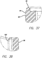
- Bottom portion 54 as depicted in FIGS. 3 , 11 , and 29-42 , comprises a pan 92 and discharge section 86 extending upwardly therefrom.
- the pan includes a peripheral wall 94 terminating at an edge 96 (e.g., see FIGS. 36 and 37 ) which provides, as further seen in FIGS. 11 , 13 and 16 a tongue-in-groove engagement with tubular wall 56 at its lower end opening 58 to provide a fluid-tight engagement between top and bottom portions 52 and 54.
- the inner surfaces of pan 92 are rounded to prevent sharp angled corners and are smoothed to enhance fluid flow and to discourage build up of matter and bacteria or other debris.
- Upwardly extending discharge section 86 which as described above extends into outlet compartment 80 of top portion 52, includes (see FIGS. 3 , 11 , 12 , 29 , 31, 32 , 34 , 35 , 39, 40 and 42 ) a tube 98 that communicates with outlet compartment 80 and opens at an exit port area 106 ( FIGS. 2 , 3 , 7 , 11 , 13 , 30 , 33 , 35 , 39 and 42 ) in pan 92 for discharge of fluids, e.g., wastewater fluid and other undesired matter, from the outlet compartment to a drain. Directed fluid flow is implemented, as depicted in FIGS.
- fluids e.g., wastewater fluid and other undesired matter
- ribs or channel guides 100 which are formed on the walls of tube 98.
- the channel guides are positioned on the interior of the drain stand, on the side near the center of the trap, with the middle guide 100' (e.g., see FIGS. 2 , 33 and 39 ) being shorter then the other, and not reaching the bottom.
- Such a trap is typically used with a horizontal drain, which is just below the bottom of the trap.
- a wall 108 is cast within discharge section 86 to separate it into a drain stand (drain tube 98) and a snorkel 110, which extends downwards to just above the level of the horizontal drain (drain tube 98).
- the snorkel avoids syphoning, by creating a "window" over the water flow to contact the air flow that is present in the drain line from the pipe air trap.
- the snorkel allows air from the drain to pass to the upper portion of the discharge compartment (just below the roof or ceiling 90) so that, even if wastewater covers the opening of the drain stand, air can still get enter and prevent syphoning.
- a key 102 and a keyway 104 are provided respectively on the interior surface of tubular wall 56 and on the backside of upwardly extending discharge section 86.
- the key and keyway are disposed to provide an orientation and proper alignment between top and bottom portions 52 and 54 and, through the orienting mechanism of keys 68 with the urinal, to place exit port area 106 adjacent the exterior drain.
Description
- The present invention relates to a flow trap, such as a cartridge used in waterfree urinals having an odor-preventing oily sealant closure mechanism and, in particular, to improving flow trap life and usability, including a reduction in the amount or volume of the odor-preventing oily sealant needed for its purpose of acting as a barrier to drain odors.
- Syphoning is a significant problem with waterfree traps. Janitors typically clean individual traps by dumping a bucket of water over the trap, thereby flushing out the malodorous waste water. Unfortunately, such dumping can overwhelm the ability of the drain stand or drain tube to receive the excess water, such as by completely filling the discharge or outlet compartment to its ceiling, thus creating a syphon effect, which thereby sucks the wastewater and sealant from the entry compartment. This problem can be created also by other events, such as through a sudden and heavy use. Regardless of the form of the event, the sealant is lost and, with it, its odor fighting capability. Furthermore, when sealant is lost through such events, the remaining sealant must be sufficient in quantity to act as an odor barrier; however, when the surface area of the wastewater and the sealant floating thereon in the inlet compartment is largely exposed under the cartridge opening, such remaining sealant may, over a period of time, become insufficient to serve its purpose and, therefore, decrease the useful life of the cartridge, thus leading to increased cost of cartridge replacement or possible replenishment of sealant. Alternatively, a cartridge must incorporate an unnecessarily larger quantity of sealant.
-
WO 2007/149379 A2 discloses a cartridge for placement in a urinal including a chamber having an entry for receiving wastewater, a modicum of sealant floatable on the wastewater in the chamber for functioning as a barrier to orders that may otherwise emanate from the wastewater and the chamber and sealant reservoir coupled to the chamber for containing a supply of the sealant.
US 817,469 discloses a non-syphoning trap, comprising a body having inlet and discharge pipes, and an air-passage communicating with the interior of the body of the trap and connected with the discharge-pipe at a point below the body of the trap.DE 464 598 discloses a water closure for waste pipes with a U-shaped part. - These and other problems are successfully addressed and overcome by the present invention according to the enclosed claims. The ceiling of the entry compartment is lowered and a throat or other small entry is positioned between the cartridge opening and the entry compartment ceiling, so as to reduce the area of sealant needed to act as an odor barrier to that of the throat as compared to the larger exposed area of prior cartridges. Further, a snorkel is incorporated in the drain stand or tube. Additionally, ribs in the drain stand improves flow or channeling of the wastewater or urine.
- By lowering the ceiling over the entry compartment, in effect to position it slightly lower then the overflow level of the drain stand in the discharge compartment, there is the likelihood of having little or no air over the sealant except for the small area under the entry opening. This reduces odor because there is a smaller exposed liquid area.
- The area of the drain stand is increased to reduce clogging. A greater surface or overflow area is present towards the center of the trap, from whence wastewater comes, which reduces the height that wastewater can reach before it tumbles over the edge; this also reduces the chance of wastewater covering the entire surface of the drain stand.
- The entry into the trap is enlarged without being segmented and, therefore, is less prone to catching hair.
- The overflow end of drain stand angled upwards away from center, as contrasted to the prior unit which had a horizontal surface. Angling avoids syphoning which can occur when the top of the drain stand is completely covered by liquid, such as in a bucket dump. The waste water is forced to reach a height well above the overflow level to completely or, at least better fill the opening up with water and reduce or eliminate any air pocket.
- The channel guides, preferably, three in number, are positioned on the interior of the drain stand, on the side near the center of the trap, with the middle guide shorter then the other (not reaching the bottom). Traps are typically used with a horizontal drain, which is just below the bottom of the trap. Guiding the flow of wastewater towards the center, away from the wall of the drain stand near the center of the trap, keeps the wastewater flowing to the center of the drain and not depositing sediment on the bottom of the housing, which builds up and blocks the unit. Further accomplished by the middle guide not reaching the bottom, which moves the two streams together towards the center.
- The wall separating the drain stand from the snorkel extends downwards to just below the outer wall of the snorkel.
- Syphoning is avoided by creating a "window" over the water-flow to contact-airflow that is present in drain line from pipe air trap.
- The snorkel allows air from the drain to pass to the upper portion of the discharge compartment, just below the roof, so that, even if wastewater covers the opening of the drain stand, air can still enter and prevent syphoning.
- Enlargement of the drain channel reduces or eliminates clogs in the drain tube.
- Other aims and advantages, as well as a more complete understanding of the present invention, will appear from the following explanation of exemplary embodiments and the accompanying drawings thereof.
-
-
FIG. 1 is a perspective view of a urinal cartridge as embodied in the present invention, as viewed downwardly towards its top; -
FIG. 2 is a perspective view of the urinal cartridge as depicted inFIG. 1 , as viewed upwardly towards its bottom; -
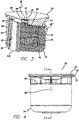
FIG. 3 is a perspective view of the urinal cartridge in cutaway cross-section, as depicted inFIGS. 1 and 2 ; -
FIG. 3A is a perspective view of the urinal cartridge, angled differently from that as illustrated inFIG. 3 , in cutaway cross-section as depicted inFIGS. 1 and 2 ; -
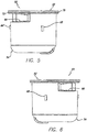
FIG. 4 is a side view of the urinal cartridge as shown inFIGS. 1 and 2 -
FIG. 5 is a side view of the urinal cartridge taken 90° from that as illustrated inFIG. 4 ; -
FIG. 6 is a side view of the urinal cartridge taken 180° from that as illustrated inFIG. 5 ; -
FIG. 7 is a side view of the urinal cartridge taken 180° from that as illustrated inFIG. 4 ; -
FIG. 8 is a top view of the cartridge depicted inFIG. 4 ; -
FIG. 9 is a detail of the cartridge taken alongcutaway line 9 ofFIG. 8 ; -
FIG. 10 is a bottom view of the cartridge depicted inFIG. 4 ; -
FIG. 11 is a cross-sectional view of the cartridge shown inFIG. 4 , taken along line 11-11 thereof; -
FIG. 11A is a detail of the cartridge taken alongcutaway line 11A ofFIG. 11 ; -
FIG. 12 is a detail of the cartridge taken alongcutaway line 12 ofFIG. 11 ; -
FIG. 13 is a detail of the cartridge taken alongcutaway line 13 ofFIG. 11 ; -
FIG. 14 is a cross-sectional view of the cartridge illustrated inFIG. 7 , taken along line 14-14 thereof; -
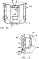
FIG. 15 is a cross-sectional view of the cartridge illustrated inFIG. 10 , taken along line 15-15 thereof; -
FIG. 16 is a detail of the cartridge taken alongcutaway line 16 ofFIG. 15 ; -
FIG. 17 is a perspective view of the top of the urinal cartridge as previously depicted, as viewed downwardly towards its top; -
FIG. 18 is a perspective view of the top of the urinal cartridge as previously depicted, as viewed downwardly towards its top, similarly as shown inFIG. 17 , but turned 90° therefrom; -
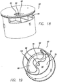
FIG. 19 is a perspective view of the top of the urinal cartridge as previously depicted, as viewed upwardly at its under side; -
FIG. 20 is a side view of the cartridge top; -
FIG. 21 is a cross-sectional view of the cartridge top taken along line 21-21 ofFIG. 20 ; -
FIG. 22 is a top view of the cartridge top; -
FIG. 23 is a cross-sectional view of the cartridge top taken along line 23-23 ofFIG. 22 ; -
FIG. 24 is a detail of the cartridge taken alongcutaway line 24 ofFIG. 23 ; -
FIG. 25 is a bottom view of the cartridge top similar to that shown inFIG. 21 but not in cross-section; -
FIG. 26 is a cross-sectional view of the cartridge top taken along line 26-26 ofFIG. 25 ; -
FIG. 27 is a cross-sectional view of the cartridge top taken along line 27-27 ofFIG. 25 ; -
FIG. 28 is a detail of the cartridge top taken alongcutaway line 28 ofFIG. 26 ; -
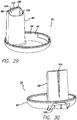
FIG. 29 is a perspective view of the bottom of the urinal cartridge as previously depicted, as viewed downwardly towards its top; -
FIG. 30 is a perspective view of the urinal cartridge bottom as depicted inFIG. 29 but turned at an angle therefrom, as viewed somewhat downwardly towards its top; -
FIG. 31 is a perspective view of the urinal cartridge bottom as depicted inFIG. 29 but turned at an angle therefrom, as viewed essentially downwardly towards its top; -
FIG. 32 is a perspective view of the urinal cartridge bottom as depicted inFIG. 29 , as viewed upwardly towards its bottom; -
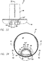
FIG. 33 is a side view of the cartridge bottom, as similarly viewed as inFIG. 30 and slightly rotated from the view depicted therein; -
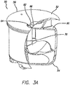
FIG. 34 is a top view of the cartridge bottom; -
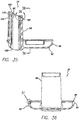
FIG. 35 is a cross-sectional view of the cartridge bottom taken along line 35-35 ofFIG. 33 ; -
FIG. 36 is a cross-sectional view of the cartridge bottom taken along line 36-36 ofFIG. 35 ; -
FIG. 37 is a detail of the cartridge bottom taken alongcutaway line 37 ofFIG. 36 ; -
FIG. 38 is a detail of the cartridge bottom taken alongcutaway line 38 ofFIG. 35 ; -
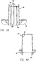
FIG. 39 is a cross-sectional view of the cartridge bottom taken along line 39-39 ofFIG. 34 ; -
FIG. 40 is a cross-sectional view of the cartridge bottom taken along line 40-40 ofFIG. 34 ; -
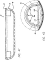
FIG. 41 is a cross-sectional view of the cartridge bottom taken along line 41-41 ofFIG. 34 ; and -
FIG. 42 is a detail of the cartridge bottom taken along cutaway line 42 ofFIG. 34 . - Accordingly, as illustrated in
FIGS. 1-18 , acartridge 50, such as capable of being inserted into a urinal housing, includes a top ortop portion 52 and bottom orbottom portion 54. Such a cartridge is sometimes referred to as an "oil sealant-preserving drain odor trap."Cartridge 50 is capable of acting as a flow trap for urine or other generally fluid waste products. As shown inFIGS. 3 ,11 and 11A ,wastewater 55, such as a fluid with urine therein, and an oilyliquid odor sealant 57 floating on the wastewater is contained within the cartridge, as described in above-cited Applications No.11/812,242 60/878,635 11/032,310 11/032,508 - With reference also to
FIGS. 19-28 ,top portion 52 has a cylindrical configuration defined by atubular wall 56 terminated by anopening 58 at its lower end and atop wall 60 at its upper end. The top wall is sloped downwardly from its outer edge to a flat, generally horizontalflat center portion 62 in which anentry opening 64 is disposed (see, for example,FIGS. 1 ,3 ,3A ,8 ,17 ,18 ,22 and 23 ) to act as a urine inlet. Ahole 66 is centrally positioned withincenter portion 62.Top portion 60 is further provided with threekeys 68, of which one 68' may be of different length than the other two (e.g., seeFIGS. 1-6 ), for purposes of properly placing and orientingcartridge 50 within a urinal, as more fully described inU.S. Pat. No. 6,644,339 . -
Top wall 60 is provided with arecess 70, for example as shown inFIGS. 5 and11 , at its outer periphery to accept a seal, such as O-ring seal 72. -
Top wall 60 oftop portion 52 is further provided with openings 74 (e.g., seeFIGS. 1 ,8 ,11 ,17 and23 ), which act as air vents that communicate with the interior ofcartridge 50. In the event that one opening becomes clogged, such as by evaporated urine residue when the urinal is in use, there will be at least one that remains open.Openings 74 also provide a means by which a tool may be inserted therein for the purpose of inserting and removing the cartridge into and from a urinal, as also described inU.S. Patents No. 5,711,037 and No.6,425,411 andU.S. publication No. 2005/0229297 . - As best shown in
FIGS. 3 ,3A ,11 ,14 ,19 ,23 and25 , the interior oftop portion 52 is divided by a bowedvertical separator 76 into two compartments, respectively aninlet compartment 78 and an outlet compartment 80 (seeFIGS. 19 ,21 and23 ).Vertical separator 76 is secured or molded to the interior surface oftubular wall 56 and to the underside oftop wall 60 in any convenient manner. The bottom end of the vertical separator terminates in an end or terminus 82 (seeFIGS. 11, 12 and16 ) which is disposed to be connected to abaffle 84. When top andbottom portions FIGS. 10 ,11 ,14 ,29-36 ,39, 40 and42 ) ofbottom portion 54 extends intooutlet compartment 80,inlet compartment 78 andoutlet compartment 80 have generally equal volumes. It is important that the compartment volumes be made as equal as possible to ensure that the pressures on both sides ofvertical separator 76 remain equal during use of the cartridge. Such equally effected pressure helps to minimize syphoning or, alternatively, to maximize resistance to syphoning between the compartments and, of particular importance, of sucking the sealant from the inlet compartment to the outlet compartment. Thus, the usable life of the cartridge is improved by avoiding premature failure thereof. Additionally, any impediment to liquid flow in minimized. - As distinguished from aforementioned applications No.
11/812,242 60/878,635 11/032,310 11/032,508 FIGS. 1 ,3 ,8 ,9 ,11 and 11A ,cartridge 50 opens to its exterior essentially through a single entry 64 (and, to a minor extent, via hole 66) that communicates withwastewater inlet compartment 78 through a throat 88 (e.g., seeFIGS. 3 ,11 ,11A ,15 ,19 ,21 ,23 ,25 ,27, and 28 ).Single entry 64 is provided with a crescent shape which is intended to reduce the chances of hair from being caught in the entry, as contrasted with multiport entries having bars. Furthermore, as depicted inFIGS. 3-6 ,11 ,11A ,15 ,17 ,23 ,29, 30 and33 ,inlet compartment 78 is closed at its upper side by aceiling 90. This ceiling over the entry compartment has been lowered, as distinguished from prior cartridges, so that it is slightly lower then the overflow level of the drain stand in the discharge compartment. Thus, there is no air over the sealant except for the small area under the entry opening and the small amount ofsealant 57 residing inthroat 88. In addition, even if no sealant were present within the throat to act as an odor barrier, there would be only a small area ofwastewater 55 within the throat which would be exposed to the air external to the cartridge and, therefore, a lesser opportunity of odor to emanate to the environment outside of the cartridge. -
Bottom portion 54, as depicted inFIGS. 3 ,11 , and29-42 , comprises apan 92 anddischarge section 86 extending upwardly therefrom. The pan includes aperipheral wall 94 terminating at an edge 96 (e.g., seeFIGS. 36 and37 ) which provides, as further seen inFIGS. 11 ,13 and16 a tongue-in-groove engagement withtubular wall 56 at itslower end opening 58 to provide a fluid-tight engagement between top andbottom portions pan 92 are rounded to prevent sharp angled corners and are smoothed to enhance fluid flow and to discourage build up of matter and bacteria or other debris. - Upwardly extending
discharge section 86, which as described above extends intooutlet compartment 80 oftop portion 52, includes (seeFIGS. 3 ,11 ,12 ,29 ,31, 32 ,34 ,35 ,39, 40 and42 ) atube 98 that communicates withoutlet compartment 80 and opens at an exit port area 106 (FIGS. 2 ,3 ,7 ,11 ,13 ,30 ,33 ,35 ,39 and42 ) inpan 92 for discharge of fluids, e.g., wastewater fluid and other undesired matter, from the outlet compartment to a drain. Directed fluid flow is implemented, as depicted inFIGS. 2 ,7 ,10 ,11 ,14 ,29 ,31, 32 ,34 ,35 ,38 ,39 and42 , by three vertically extending ribs or channel guides 100 which are formed on the walls oftube 98. The channel guides are positioned on the interior of the drain stand, on the side near the center of the trap, with the middle guide 100' (e.g., seeFIGS. 2 ,33 and39 ) being shorter then the other, and not reaching the bottom. Such a trap is typically used with a horizontal drain, which is just below the bottom of the trap. By so guiding the flow of wastewater towards the center, away from the wall of the drain stand near the center of the trap, the wastewater is kept flowing to the center of the drain, which helps to avoid the depositing of sediment on the bottom of the housing, which otherwise would build up and block the cartridge. Furthermore, because the middle guide does not reach the bottom, the two streams tend to move together towards the center of the drain. - As illustrated in
FIGS. 10 ,11 ,13, 14 ,29 ,31 ,34 ,35 and42 , awall 108 is cast withindischarge section 86 to separate it into a drain stand (drain tube 98) and asnorkel 110, which extends downwards to just above the level of the horizontal drain (drain tube 98). The snorkel avoids syphoning, by creating a "window" over the water flow to contact the air flow that is present in the drain line from the pipe air trap. Specifically, the snorkel allows air from the drain to pass to the upper portion of the discharge compartment (just below the roof or ceiling 90) so that, even if wastewater covers the opening of the drain stand, air can still get enter and prevent syphoning. - A key 102 and a keyway 104 (see
FIGS. 11 ,13 ,14 ,19 ,21 ,26 ,29-31 ,33-35 and42 ) are provided respectively on the interior surface oftubular wall 56 and on the backside of upwardly extendingdischarge section 86. The key and keyway are disposed to provide an orientation and proper alignment between top andbottom portions keys 68 with the urinal, to placeexit port area 106 adjacent the exterior drain. - Although the invention has been described with respect to particular embodiments thereof, it should be realized that various changes and modifications may be made therein without departing from the spirit and scope of the invention.
Claims (8)
- A wastewater cartridge having an upper wall (60), an opening (64) therein for receipt of wastewater, an inlet compartment (78) generally under the opening for receipt of the wastewater from the opening and a sealant which is contained in the inlet compartment (78), which is floatable on the wastewater therein and which is disposed to act as a barrier to external drain and other odors, an outlet compartment (80) which is coupled to the inlet compartment (78), and a drain tube (98) which has an overflow level and which is coupled between the outlet compartment (80) and an external drain,
a ceiling (90) of given area for the inlet compartment (78), which said ceiling is spaced from the upper wall (60) and from the wastewater-receiving opening (64), and which is lower than the overflow level of the drain tube; and
a throat (88) which connects the inlet compartment (78) to the wastewater-receiving opening (64), which has a cross-sectional area that is less than the area of said ceiling (90), and which has a construction that is sized to enable said throat (88) to contain an amount of the sealant such that the amount of the sealant, as acting as the barrier and as contained within said throat (88), is less than the remainder of the sealant under said ceiling (90) which floats on the wastewater in said inlet compartment (78),
wherein a ceiling surface of the ceiling (90) between the upper wall (60) and the inlet compartment (78) extends outwardly from a lower end of the throat (88) to an outer periphery of the inlet compartment (78), characterized in that the cartridge is configured so that all of the sealant in the inlet compartment (78) is contained under or in the throat (88) and under the ceiling (90). - The wastewater cartridge according to claim 1 in which the sealant extends laterally beyond the throat so that the majority of the surface of the sealant is not exposed to air.
- The wastewater cartridge according to claim 1 further including a discharge section (86) coupled between said outlet compartment (80) and the external drain, a wall (108) disposed in said discharge section and separating said discharge section into the drain tube (98) and a snorkel (110) which extends downwards generally to above the level of said drain tube, whereby said snorkel allows any air from the external drain to pass to said outlet compartment generally below said ceiling (90) so that, should wastewater covers the opening of said drain tube, such air is permitted to enter and prevent siphoning.
- The wastewater cartridge according to claim 1 further including:a discharge section (86) which is coupled between said outlet compartment and the external drain and which includes the drain tube (98) having walls surrounding a center and communicating with said outlet compartment (80) and opens at an exit port area (106) for discharge of the wastewater fluid from said outlet compartment to the drain; anda channel guide mechanism (100) formed within said tube guiding flow of the wastewater towards said drain tube center, and away from said drain tube walls, whereby the wastewater is kept flowing towards said drain tube center to avoid deposit of any sediment contained in the wastewater.
- The wastewater cartridge according to claim 4 wherein said channel guide mechanism includes three vertically extending ribs, with the middle one of said ribs being shorter then said outer ribs so as to guide the wastewater flow towards said drain tube center and away from its walls.
- The wastewater cartridge according to claim 1 wherein said sealant layer extends flush against said ceiling and into said throat.
- A method for creating an odor seal and conserving the quantity of an odor sealant in a wastewater cartridge having an upper wall (60), an opening (64) therein for receipt of wastewater, an outlet compartment (80) which is coupled to an external drain and which has an overflow level, an inlet compartment (78) generally under the opening for receipt of the wastewater from the opening and a sealant which is contained in the inlet compartment, which is floatable on the wastewater therein and which is disposed to act as a barrier to external drain and other odors, comprising the steps of:spacing a ceiling (90) of given area of the inlet compartment (78), from the upper wall (60) and from the wastewater-receiving opening (64), which ceiling is lower than the overflow level of the external drain;connecting the inlet compartment (78) to the wastewater-receiving opening (64) by a throat (88) having a cross-sectional area which is less than the area of the ceiling, andproviding an amount of the sealant in the throat (88) so that the amount of the sealant, as acting as the barrier and as contained by and within the throat, is less than the remainder of the sealant under the ceiling (90) which floats on the wastewater in the inlet compartment (78), wherein all of the sealant in the inlet compartment (78) is contained under or in the throat (88) and under the ceiling (90),wherein a ceiling surface of the ceiling (90) between the upper wall (60) and the inlet compartment (78) extends outwardly from a lower end of the throat (88) to an outer periphery of the inlet compartment (78).
- The method according to claim 7 further comprising the characterizing step of extending the sealant layer flush against the ceiling and into the throat.
Applications Claiming Priority (2)
| Application Number | Priority Date | Filing Date | Title |
|---|---|---|---|
| US21011509P | 2009-03-12 | 2009-03-12 | |
| PCT/US2010/000698 WO2010104561A1 (en) | 2009-03-12 | 2010-03-09 | Anti-siphon trap with snorkel for a waterless urinal |
Publications (2)
| Publication Number | Publication Date |
|---|---|
| EP2406436A1 EP2406436A1 (en) | 2012-01-18 |
| EP2406436B1 true EP2406436B1 (en) | 2018-08-08 |
Family
ID=42272573
Family Applications (1)
| Application Number | Title | Priority Date | Filing Date |
|---|---|---|---|
| EP10718746.0A Active EP2406436B1 (en) | 2009-03-12 | 2010-03-09 | Odor trap for a waterless urinal |
Country Status (19)
| Country | Link |
|---|---|
| US (1) | US8646117B2 (en) |
| EP (1) | EP2406436B1 (en) |
| JP (1) | JP5494988B2 (en) |
| KR (1) | KR20120018111A (en) |
| CN (1) | CN102482870B (en) |
| AU (1) | AU2010223103B2 (en) |
| CA (1) | CA2754814A1 (en) |
| CO (1) | CO6420366A2 (en) |
| CR (1) | CR20110510A (en) |
| DK (1) | DK2406436T3 (en) |
| ES (1) | ES2694075T3 (en) |
| IL (1) | IL214582A (en) |
| MX (1) | MX2011009470A (en) |
| MY (1) | MY157853A (en) |
| NZ (1) | NZ594763A (en) |
| RU (1) | RU2542769C2 (en) |
| SG (1) | SG173704A1 (en) |
| TR (1) | TR201816324T4 (en) |
| WO (1) | WO2010104561A1 (en) |
Families Citing this family (9)
| Publication number | Priority date | Publication date | Assignee | Title |
|---|---|---|---|---|
| WO2012093357A1 (en) * | 2011-01-05 | 2012-07-12 | Amphicom Investments Cc | In-line water trap |
| CN102644315A (en) * | 2012-03-27 | 2012-08-22 | 北京康之维科技有限公司 | Multilayer water seal drainage method and water seal device |
| US20140090157A1 (en) * | 2012-10-03 | 2014-04-03 | Guillermo A. Ramirez | Waterless urinal cartridge |
| TWI593861B (en) | 2013-04-26 | 2017-08-01 | 發肯免水科技公司 | Housing for a hybrid flushing system, a cartridge for a hybrid flushing system and a hybrid flushing system |
| EP3004476A4 (en) * | 2013-05-28 | 2017-11-15 | Falcon Waterfree Technologies, LLC | Splash-reducing and velocity-increasing cartridge exit |
| TWI580847B (en) | 2013-05-28 | 2017-05-01 | 發肯免水科技公司 | Fluid inlet portion for a waterless urinal cartridge |
| US10197430B2 (en) | 2014-01-20 | 2019-02-05 | Falcon Waterfree Technologies, Llc | Visual indicator |
| US11766930B2 (en) * | 2019-09-18 | 2023-09-26 | Ford Global Technologies, Llc | Anti-siphon device and method for operation of an anti-siphon device |
| CN111255036B (en) * | 2020-01-21 | 2020-10-23 | 四川旅发环保科技有限公司 | Toilet oil seal recycling method |
Family Cites Families (14)
| Publication number | Priority date | Publication date | Assignee | Title |
|---|---|---|---|---|
| DE464598C (en) * | 1928-08-22 | Kenneth Cecil Hanson | Water seal for waste pipes with a U-shaped part adjoining the inlet, in which a narrow compensation channel is provided in the middle partition between the sloping and ascending leg parallel to the latter | |
| US637285A (en) * | 1898-03-07 | 1899-11-21 | John M E Riedel | Funnel. |
| CH18658A (en) * | 1899-05-04 | 1900-02-15 | Oedoen Palotai | Innovation in odor traps to prevent them from being emptied |
| US817469A (en) * | 1905-06-29 | 1906-04-10 | Edward Alexander Cleland | Non-siphoning trap. |
| IL124063A (en) * | 1995-10-25 | 2001-07-24 | Gorges Ditmar L | Odor trap apparatus and a system for draining waste water |
| US6425411B1 (en) * | 1995-10-25 | 2002-07-30 | Ditmar L. Gorges | Oil sealant-preserving drain odor trap |
| US6644339B2 (en) * | 2000-02-29 | 2003-11-11 | Falcon Waterless Technologies | Horizontal-flow trap and housing assembly with odor preventing closure mechanism |
| GB0105842D0 (en) * | 2001-03-09 | 2001-04-25 | Hall Kelvin E | Waste outlet assembly |
| CA2446647C (en) * | 2001-05-07 | 2007-11-27 | Falcon Waterfree Technologies Llc | Liquid flow meter |
| US7575022B2 (en) * | 2003-08-25 | 2009-08-18 | Falcon Waterfree Technologie | Diverter, liquid-level indicator and chemical pre-treatment and post-treatment implementations useful in waterless urinals |
| US7571741B2 (en) * | 2003-08-25 | 2009-08-11 | Falcon Waterfree Technologies | Flow trap with compartment separator and baffle for use in a waterless urinal |
| CN1930347A (en) * | 2004-01-09 | 2007-03-14 | 猎鹰无水技术公司 | Diverter, liquid-level indicator and chemical pre-treatment and post-treatment implementations useful in waterless urinals |
| WO2005071171A1 (en) * | 2004-01-09 | 2005-08-04 | Falcon Waterfree Technologies | Cartridge-removing tool for use in waterless urinals |
| US20080028504A1 (en) * | 2006-06-16 | 2008-02-07 | Higgins Michael L | Urinal cartridge with improved performance |
-
2010
- 2010-03-09 CA CA 2754814 patent/CA2754814A1/en not_active Abandoned
- 2010-03-09 DK DK10718746.0T patent/DK2406436T3/en active
- 2010-03-09 EP EP10718746.0A patent/EP2406436B1/en active Active
- 2010-03-09 RU RU2011141260/13A patent/RU2542769C2/en not_active IP Right Cessation
- 2010-03-09 SG SG2011058765A patent/SG173704A1/en unknown
- 2010-03-09 KR KR1020117021167A patent/KR20120018111A/en not_active Application Discontinuation
- 2010-03-09 US US12/661,027 patent/US8646117B2/en active Active
- 2010-03-09 JP JP2011554037A patent/JP5494988B2/en not_active Expired - Fee Related
- 2010-03-09 NZ NZ59476310A patent/NZ594763A/en not_active IP Right Cessation
- 2010-03-09 CN CN201080011675.6A patent/CN102482870B/en active Active
- 2010-03-09 TR TR2018/16324T patent/TR201816324T4/en unknown
- 2010-03-09 MY MYPI2011003670A patent/MY157853A/en unknown
- 2010-03-09 MX MX2011009470A patent/MX2011009470A/en active IP Right Grant
- 2010-03-09 ES ES10718746.0T patent/ES2694075T3/en active Active
- 2010-03-09 AU AU2010223103A patent/AU2010223103B2/en active Active
- 2010-03-09 WO PCT/US2010/000698 patent/WO2010104561A1/en active Application Filing
-
2011
- 2011-08-10 IL IL214582A patent/IL214582A/en not_active IP Right Cessation
- 2011-08-31 CO CO11111737A patent/CO6420366A2/en active IP Right Grant
- 2011-09-29 CR CR20110510A patent/CR20110510A/en not_active Application Discontinuation
Non-Patent Citations (1)
| Title |
|---|
| None * |
Also Published As
| Publication number | Publication date |
|---|---|
| TR201816324T4 (en) | 2018-11-21 |
| CR20110510A (en) | 2012-05-29 |
| CO6420366A2 (en) | 2012-04-16 |
| CN102482870A (en) | 2012-05-30 |
| IL214582A0 (en) | 2011-09-27 |
| KR20120018111A (en) | 2012-02-29 |
| JP2012520404A (en) | 2012-09-06 |
| US8646117B2 (en) | 2014-02-11 |
| IL214582A (en) | 2014-09-30 |
| CN102482870B (en) | 2015-03-18 |
| MX2011009470A (en) | 2012-01-12 |
| RU2011141260A (en) | 2013-04-27 |
| MY157853A (en) | 2016-07-29 |
| AU2010223103B2 (en) | 2016-09-29 |
| ES2694075T3 (en) | 2018-12-17 |
| JP5494988B2 (en) | 2014-05-21 |
| AU2010223103A1 (en) | 2011-08-25 |
| NZ594763A (en) | 2014-01-31 |
| EP2406436A1 (en) | 2012-01-18 |
| WO2010104561A4 (en) | 2010-11-11 |
| US20100230333A1 (en) | 2010-09-16 |
| DK2406436T3 (en) | 2018-11-26 |
| WO2010104561A1 (en) | 2010-09-16 |
| SG173704A1 (en) | 2011-09-29 |
| CA2754814A1 (en) | 2010-09-16 |
| RU2542769C2 (en) | 2015-02-27 |
Similar Documents
| Publication | Publication Date | Title |
|---|---|---|
| EP2406436B1 (en) | Odor trap for a waterless urinal | |
| US6944890B1 (en) | Automatic cleaning assembly for a toilet bowl | |
| RU2383690C2 (en) | Water seal for sanitary ware | |
| US7661438B2 (en) | Water saver fill valve and assembly | |
| US9062795B2 (en) | Water saver fill valve and assembly | |
| US8387652B2 (en) | Water saver fill valve and assembly | |
| EP2568861B1 (en) | Trap and drain assembly for draining waste liquids while blocking odors | |
| US6704945B2 (en) | Dual inlet flush valve system for gravity operated toilets | |
| US6449779B1 (en) | Automatic toilet cleaning dispenser assembly | |
| KR20100112452A (en) | The doesn't need water type of urinal | |
| KR102251978B1 (en) | Apparatus for Removing Odor from Toilet Bowl | |
| KR100830205B1 (en) | Cleaning liquid of low specificgravity using the toilet bowl | |
| US20230265642A1 (en) | Flush valve and toilet assembly | |
| CN215858047U (en) | Water-saving valve for toilet cistern | |
| KR101906976B1 (en) | Water-saving toilet bowl | |
| JP2008050853A (en) | Drain valve | |
| JP4364398B2 (en) | Sewer | |
| US4965892A (en) | Syphonic flush toilet | |
| KR100412538B1 (en) | Sewage drainer | |
| JP3190162U (en) | Drain trap assembly for discharging waste liquid while blocking odor | |
| PL186895B1 (en) | Outlet valve | |
| GB2134555A (en) | Water closets | |
| JPH10311083A (en) | Intercepter |
Legal Events
| Date | Code | Title | Description |
|---|---|---|---|
| PUAI | Public reference made under article 153(3) epc to a published international application that has entered the european phase |
Free format text: ORIGINAL CODE: 0009012 |
|
| 17P | Request for examination filed |
Effective date: 20110811 |
|
| AK | Designated contracting states |
Kind code of ref document: A1 Designated state(s): AT BE BG CH CY CZ DE DK EE ES FI FR GB GR HR HU IE IS IT LI LT LU LV MC MK MT NL NO PL PT RO SE SI SK SM TR |
|
| DAX | Request for extension of the european patent (deleted) | ||
| 17Q | First examination report despatched |
Effective date: 20140417 |
|
| STAA | Information on the status of an ep patent application or granted ep patent |
Free format text: STATUS: EXAMINATION IS IN PROGRESS |
|
| GRAP | Despatch of communication of intention to grant a patent |
Free format text: ORIGINAL CODE: EPIDOSNIGR1 |
|
| STAA | Information on the status of an ep patent application or granted ep patent |
Free format text: STATUS: GRANT OF PATENT IS INTENDED |
|
| INTG | Intention to grant announced |
Effective date: 20180220 |
|
| GRAS | Grant fee paid |
Free format text: ORIGINAL CODE: EPIDOSNIGR3 |
|
| GRAA | (expected) grant |
Free format text: ORIGINAL CODE: 0009210 |
|
| STAA | Information on the status of an ep patent application or granted ep patent |
Free format text: STATUS: THE PATENT HAS BEEN GRANTED |
|
| AK | Designated contracting states |
Kind code of ref document: B1 Designated state(s): AT BE BG CH CY CZ DE DK EE ES FI FR GB GR HR HU IE IS IT LI LT LU LV MC MK MT NL NO PL PT RO SE SI SK SM TR |
|
| REG | Reference to a national code |
Ref country code: GB Ref legal event code: FG4D |
|
| REG | Reference to a national code |
Ref country code: CH Ref legal event code: EP Ref country code: AT Ref legal event code: REF Ref document number: 1027186 Country of ref document: AT Kind code of ref document: T Effective date: 20180815 |
|
| REG | Reference to a national code |
Ref country code: IE Ref legal event code: FG4D |
|
| REG | Reference to a national code |
Ref country code: DE Ref legal event code: R096 Ref document number: 602010052505 Country of ref document: DE |
|
| REG | Reference to a national code |
Ref country code: DK Ref legal event code: T3 Effective date: 20181119 |
|
| REG | Reference to a national code |
Ref country code: NL Ref legal event code: MP Effective date: 20180808 |
|
| REG | Reference to a national code |
Ref country code: ES Ref legal event code: FG2A Ref document number: 2694075 Country of ref document: ES Kind code of ref document: T3 Effective date: 20181217 |
|
| REG | Reference to a national code |
Ref country code: LT Ref legal event code: MG4D |
|
| REG | Reference to a national code |
Ref country code: AT Ref legal event code: MK05 Ref document number: 1027186 Country of ref document: AT Kind code of ref document: T Effective date: 20180808 |
|
| PG25 | Lapsed in a contracting state [announced via postgrant information from national office to epo] |
Ref country code: BG Free format text: LAPSE BECAUSE OF FAILURE TO SUBMIT A TRANSLATION OF THE DESCRIPTION OR TO PAY THE FEE WITHIN THE PRESCRIBED TIME-LIMIT Effective date: 20181108 Ref country code: NL Free format text: LAPSE BECAUSE OF FAILURE TO SUBMIT A TRANSLATION OF THE DESCRIPTION OR TO PAY THE FEE WITHIN THE PRESCRIBED TIME-LIMIT Effective date: 20180808 Ref country code: LT Free format text: LAPSE BECAUSE OF FAILURE TO SUBMIT A TRANSLATION OF THE DESCRIPTION OR TO PAY THE FEE WITHIN THE PRESCRIBED TIME-LIMIT Effective date: 20180808 Ref country code: IS Free format text: LAPSE BECAUSE OF FAILURE TO SUBMIT A TRANSLATION OF THE DESCRIPTION OR TO PAY THE FEE WITHIN THE PRESCRIBED TIME-LIMIT Effective date: 20181208 Ref country code: PL Free format text: LAPSE BECAUSE OF FAILURE TO SUBMIT A TRANSLATION OF THE DESCRIPTION OR TO PAY THE FEE WITHIN THE PRESCRIBED TIME-LIMIT Effective date: 20180808 Ref country code: AT Free format text: LAPSE BECAUSE OF FAILURE TO SUBMIT A TRANSLATION OF THE DESCRIPTION OR TO PAY THE FEE WITHIN THE PRESCRIBED TIME-LIMIT Effective date: 20180808 Ref country code: GR Free format text: LAPSE BECAUSE OF FAILURE TO SUBMIT A TRANSLATION OF THE DESCRIPTION OR TO PAY THE FEE WITHIN THE PRESCRIBED TIME-LIMIT Effective date: 20181109 Ref country code: NO Free format text: LAPSE BECAUSE OF FAILURE TO SUBMIT A TRANSLATION OF THE DESCRIPTION OR TO PAY THE FEE WITHIN THE PRESCRIBED TIME-LIMIT Effective date: 20181108 Ref country code: SE Free format text: LAPSE BECAUSE OF FAILURE TO SUBMIT A TRANSLATION OF THE DESCRIPTION OR TO PAY THE FEE WITHIN THE PRESCRIBED TIME-LIMIT Effective date: 20180808 Ref country code: FI Free format text: LAPSE BECAUSE OF FAILURE TO SUBMIT A TRANSLATION OF THE DESCRIPTION OR TO PAY THE FEE WITHIN THE PRESCRIBED TIME-LIMIT Effective date: 20180808 |
|
| PG25 | Lapsed in a contracting state [announced via postgrant information from national office to epo] |
Ref country code: HR Free format text: LAPSE BECAUSE OF FAILURE TO SUBMIT A TRANSLATION OF THE DESCRIPTION OR TO PAY THE FEE WITHIN THE PRESCRIBED TIME-LIMIT Effective date: 20180808 Ref country code: LV Free format text: LAPSE BECAUSE OF FAILURE TO SUBMIT A TRANSLATION OF THE DESCRIPTION OR TO PAY THE FEE WITHIN THE PRESCRIBED TIME-LIMIT Effective date: 20180808 |
|
| PG25 | Lapsed in a contracting state [announced via postgrant information from national office to epo] |
Ref country code: EE Free format text: LAPSE BECAUSE OF FAILURE TO SUBMIT A TRANSLATION OF THE DESCRIPTION OR TO PAY THE FEE WITHIN THE PRESCRIBED TIME-LIMIT Effective date: 20180808 Ref country code: CZ Free format text: LAPSE BECAUSE OF FAILURE TO SUBMIT A TRANSLATION OF THE DESCRIPTION OR TO PAY THE FEE WITHIN THE PRESCRIBED TIME-LIMIT Effective date: 20180808 Ref country code: RO Free format text: LAPSE BECAUSE OF FAILURE TO SUBMIT A TRANSLATION OF THE DESCRIPTION OR TO PAY THE FEE WITHIN THE PRESCRIBED TIME-LIMIT Effective date: 20180808 |
|
| REG | Reference to a national code |
Ref country code: DE Ref legal event code: R097 Ref document number: 602010052505 Country of ref document: DE |
|
| PG25 | Lapsed in a contracting state [announced via postgrant information from national office to epo] |
Ref country code: SM Free format text: LAPSE BECAUSE OF FAILURE TO SUBMIT A TRANSLATION OF THE DESCRIPTION OR TO PAY THE FEE WITHIN THE PRESCRIBED TIME-LIMIT Effective date: 20180808 Ref country code: SK Free format text: LAPSE BECAUSE OF FAILURE TO SUBMIT A TRANSLATION OF THE DESCRIPTION OR TO PAY THE FEE WITHIN THE PRESCRIBED TIME-LIMIT Effective date: 20180808 |
|
| PLBE | No opposition filed within time limit |
Free format text: ORIGINAL CODE: 0009261 |
|
| STAA | Information on the status of an ep patent application or granted ep patent |
Free format text: STATUS: NO OPPOSITION FILED WITHIN TIME LIMIT |
|
| 26N | No opposition filed |
Effective date: 20190509 |
|
| PG25 | Lapsed in a contracting state [announced via postgrant information from national office to epo] |
Ref country code: SI Free format text: LAPSE BECAUSE OF FAILURE TO SUBMIT A TRANSLATION OF THE DESCRIPTION OR TO PAY THE FEE WITHIN THE PRESCRIBED TIME-LIMIT Effective date: 20180808 |
|
| PG25 | Lapsed in a contracting state [announced via postgrant information from national office to epo] |
Ref country code: MC Free format text: LAPSE BECAUSE OF FAILURE TO SUBMIT A TRANSLATION OF THE DESCRIPTION OR TO PAY THE FEE WITHIN THE PRESCRIBED TIME-LIMIT Effective date: 20180808 |
|
| REG | Reference to a national code |
Ref country code: CH Ref legal event code: PL |
|
| PG25 | Lapsed in a contracting state [announced via postgrant information from national office to epo] |
Ref country code: LU Free format text: LAPSE BECAUSE OF NON-PAYMENT OF DUE FEES Effective date: 20190309 |
|
| REG | Reference to a national code |
Ref country code: BE Ref legal event code: MM Effective date: 20190331 |
|
| PG25 | Lapsed in a contracting state [announced via postgrant information from national office to epo] |
Ref country code: IE Free format text: LAPSE BECAUSE OF NON-PAYMENT OF DUE FEES Effective date: 20190309 Ref country code: CH Free format text: LAPSE BECAUSE OF NON-PAYMENT OF DUE FEES Effective date: 20190331 Ref country code: LI Free format text: LAPSE BECAUSE OF NON-PAYMENT OF DUE FEES Effective date: 20190331 |
|
| PG25 | Lapsed in a contracting state [announced via postgrant information from national office to epo] |
Ref country code: BE Free format text: LAPSE BECAUSE OF NON-PAYMENT OF DUE FEES Effective date: 20190331 |
|
| PG25 | Lapsed in a contracting state [announced via postgrant information from national office to epo] |
Ref country code: MT Free format text: LAPSE BECAUSE OF NON-PAYMENT OF DUE FEES Effective date: 20190309 Ref country code: PT Free format text: LAPSE BECAUSE OF FAILURE TO SUBMIT A TRANSLATION OF THE DESCRIPTION OR TO PAY THE FEE WITHIN THE PRESCRIBED TIME-LIMIT Effective date: 20181208 |
|
| PG25 | Lapsed in a contracting state [announced via postgrant information from national office to epo] |
Ref country code: CY Free format text: LAPSE BECAUSE OF FAILURE TO SUBMIT A TRANSLATION OF THE DESCRIPTION OR TO PAY THE FEE WITHIN THE PRESCRIBED TIME-LIMIT Effective date: 20180808 |
|
| PG25 | Lapsed in a contracting state [announced via postgrant information from national office to epo] |
Ref country code: HU Free format text: LAPSE BECAUSE OF FAILURE TO SUBMIT A TRANSLATION OF THE DESCRIPTION OR TO PAY THE FEE WITHIN THE PRESCRIBED TIME-LIMIT; INVALID AB INITIO Effective date: 20100309 |
|
| PG25 | Lapsed in a contracting state [announced via postgrant information from national office to epo] |
Ref country code: MK Free format text: LAPSE BECAUSE OF FAILURE TO SUBMIT A TRANSLATION OF THE DESCRIPTION OR TO PAY THE FEE WITHIN THE PRESCRIBED TIME-LIMIT Effective date: 20180808 |
|
| PGFP | Annual fee paid to national office [announced via postgrant information from national office to epo] |
Ref country code: FR Payment date: 20230323 Year of fee payment: 14 Ref country code: DK Payment date: 20230323 Year of fee payment: 14 |
|
| PGFP | Annual fee paid to national office [announced via postgrant information from national office to epo] |
Ref country code: TR Payment date: 20230221 Year of fee payment: 14 Ref country code: IT Payment date: 20230321 Year of fee payment: 14 Ref country code: GB Payment date: 20230321 Year of fee payment: 14 |
|
| PGFP | Annual fee paid to national office [announced via postgrant information from national office to epo] |
Ref country code: ES Payment date: 20230420 Year of fee payment: 14 Ref country code: DE Payment date: 20230330 Year of fee payment: 14 |