EP2406131B1 - Tiltrotor aircraft and method of controlling yaw movement therefor - Google Patents
Tiltrotor aircraft and method of controlling yaw movement therefor Download PDFInfo
- Publication number
- EP2406131B1 EP2406131B1 EP09841622.5A EP09841622A EP2406131B1 EP 2406131 B1 EP2406131 B1 EP 2406131B1 EP 09841622 A EP09841622 A EP 09841622A EP 2406131 B1 EP2406131 B1 EP 2406131B1
- Authority
- EP
- European Patent Office
- Prior art keywords
- wing
- tiltrotor aircraft
- aircraft
- nacelle
- rotor
- Prior art date
- Legal status (The legal status is an assumption and is not a legal conclusion. Google has not performed a legal analysis and makes no representation as to the accuracy of the status listed.)
- Active
Links
Images




Classifications
-
- B—PERFORMING OPERATIONS; TRANSPORTING
- B64—AIRCRAFT; AVIATION; COSMONAUTICS
- B64C—AEROPLANES; HELICOPTERS
- B64C29/00—Aircraft capable of landing or taking-off vertically, e.g. vertical take-off and landing [VTOL] aircraft
- B64C29/0008—Aircraft capable of landing or taking-off vertically, e.g. vertical take-off and landing [VTOL] aircraft having its flight directional axis horizontal when grounded
- B64C29/0016—Aircraft capable of landing or taking-off vertically, e.g. vertical take-off and landing [VTOL] aircraft having its flight directional axis horizontal when grounded the lift during taking-off being created by free or ducted propellers or by blowers
- B64C29/0033—Aircraft capable of landing or taking-off vertically, e.g. vertical take-off and landing [VTOL] aircraft having its flight directional axis horizontal when grounded the lift during taking-off being created by free or ducted propellers or by blowers the propellers being tiltable relative to the fuselage
Definitions
- the present application relates to a tiltrotor aircraft.
- Tiltrotor and tiltwing aircraft operate in two modes: helicopter and airplane modes.
- helicopter mode the aircraft's rotors are positioned to create lift, thereby enabling the aircraft to achieve vertical take-off and landing.
- the aircraft is essentially a helicopter.
- the rotors are slowly tilted forward, eventually transitioning to airplane mode.
- airplane mode the aircraft is essentially a turboprop aircraft.
- a typical tiltwing aircraft transitions between helicopter and airplane mode by pivotally moving the aircraft's entire wing span to a position substantially perpendicular and horizontal to the aircraft's fuselage, respectively.
- the tiltwing configuration is ideal for reducing rotor wash interaction with the aircraft's wing during helicopter mode. But, a tilt-wing configuration has found very little application because conversion from helicopter to airplane mode, and vice-versa, is difficult and inefficient.
- a typical tiltrotor aircraft improves upon the tiltwing configuration. Unlike the tiltwing configuration, a typical tiltrotor includes fixed wing members. In helicopter mode, the aircraft's nacelles rotate to a vertical position, and as the aircraft moves forward, the nacelles rotate to a horizontal position.
- tiltrotor aircraft In some tiltrotor aircraft, a section of the wing span rotates with the nacelle assembly. This design decreases rotor wash loads on the aircraft's wings. This type of tiltrotor aircraft has found little application because of the difficulties associated with incorporating a partially rotatable wing in lieu of having a rigid whole wing.
- tiltrotor aircraft In some tiltrotor aircraft, four wing members are used in conjunction with four nacelles for purposes of lifting heavy payloads. This type of tiltrotor aircraft is known as a quad-tiltrotor aircraft.
- US 5096140 describes an aircraft with engine pods located outboard on the wings and tiltable about a transverse axis.
- a spar serves as a support for the outer wings which continue beyond the separation locations and which, together with the engine pods located there, form a unit which can be jointly swivelled or tilted.
- the present invention concerns a tiltrotor aircraft and a method for controlling yaw movement of a tiltrotor aircraft as defined by the features and steps of respectively claims 1 and 5.
- the present application discloses substantial improvements in the field of helicopters and other rotorcraft.
- the present application describes a rotatable wing extension that pivotally attaches to the outboard section of the aircraft's nacelle.
- the wing extension creates additional yaw control during helicopter mode and increases lift during airplane mode. The additional lift enables the aircraft to increase payload capacity.
- tiltwing aircraft 11 is shown in helicopter mode
- Figure 1B shows tiltwing aircraft 11 in airplane mode
- Tiltwing aircraft 11 includes a fuselage 13 having an upper surface 15 pivotally attached to a wing 17.
- Wing 17 rigidly attaches to two nacelles 19a, 19b that carry respective engines 21A, 21B and propellers 23a, 23b.
- wing 17 is positioned substantially perpendicular to fuselage 13.
- airplane mode wing 17 rotates about axis A to a position substantially parallel to fuselage 13.
- FIG. 2A a front view of a tiltrotor aircraft (not claimed) 31 is illustrated with rotatable wing sections 33a and 33b.
- Figure 2A shows aircraft 31 in helicopter mode
- Figure 2B shows aircraft 31 in airplane mode.
- Tiltrotor aircraft 31 includes a fuselage 35 rigidly attached to a wing 37.
- Wing 37 includes rotatable wing sections 33a, 33b pivotally coupled to respective fixed wing sections 39a, 39b.
- Two rotor nacelles 41A, 41 B rigidly attach to wing sections 33a, 33b and carry respective proprotors 47A, 47B.
- Two engine nacelles 43a, 43b attach to rotatable wing section 33a, 33b and carry respective engines 45a, 45b.
- rotatable wing sections 33a, 33b are positioned substantially perpendicular to wing 37 for vertical take-off and landing.
- rotatable wing sections 33a, 33b rotate about axis B to a position substantially parallel to wing 37 for horizontal flight.
- Tiltrotor aircraft 71 is shown in helicopter mode with rotor assemblies 73a, 73b positioned for vertical take-off and landing.
- Rotor assemblies 73a, 73b include respective wing extensions 75a, 75b, rotors 77A, 77B, and nacelles 79a, 79b.
- Wing members 81A, 81 B pivotally attach to respective inboard sections 78a, 78b of nacelles 79a, 79b.
- Fuselage 72 rigidly attaches to wing members 81A, 81B.
- Rotor assemblies 73a, 73b pivotally rotate relative to wing members 81A, 81 B between a helicopter mode, in which rotor assemblies 73a, 73b are tilted upward such that tiltrotor aircraft 71 flies like a conventional helicopter; and an airplane mode in which rotor assemblies 73a, 73b are tilted forward such that tiltrotor aircraft 71 flies like a conventional propeller-driven aircraft.
- wing extensions 75a, 75b are pivotally couple to respective outboard sections 80a, 80b.
- the wing extensions rotate independent of the nacelles' rotation.
- the wing extensions rigidly attach to the nacelles and rotate with the nacelles' rotation.
- Nacelles 79a, 79b carry an engine and transmission (not shown) which attach to rotors 77A, 77B.
- rotors 77A, 77B are proprotors, but it should be appreciated that any suitable rotor may be used in lieu of proprotors.
- rotors 77A, 77B create a rotor wash that exerts a downward force on wing members 81A, 81B and wing extensions 75a, 75b.
- the rotor wash can be manipulated with wing extensions 75a, 75b to create forward and reverse thrusts (see Figs. 4B, 4C ).
- a computer system or pilot could adjust the wing extension rotation to vary the magnitude of thrust, thereby controlling yaw movement. Yaw control is further discussed below in connection with Figures 4A-4D .
- Wing extension flaps 83a, 83b are pivotally coupled to respective wing extensions 75a, 75b. During airplane mode, the wing extension flaps are used for providing additional roll control.
- Figures 4A-4C illustrate side views of rotor assembly 73a as shown in Figure 3 .
- Figure 4D illustrates a top view of tiltrotor aircraft 71 as shown in Figure 3 .
- rotor assembly 73a remains substantially perpendicular to wing 81A.
- Wing extension 75a is shown attached to rotor assembly 73a in positions C, D, and E relative to the rotor's axis of rotation.
- a wing extension chord 76 is aligns with the rotor axis of rotation; whereas, chord 76 does not align with the rotor axis of rotation in positions D and E.
- Joint 85a pivotally attaches wing extension 75a and nacelle 79a. It should be understood that some embodiments include joint 85a, while other embodiments could include any suitable device for attaching wing extension 75a to nacelle 79a. It should be appreciated that a hydraulic, motor, pneumatic, or any suitable device could be used to rotate wing extensions 75a, 75b about joint 85a.
- FIG. 4A shows rotor wash (not shown) from rotor 77A creates a downward force F on wing member 81A and wing extension 75a.
- This figure shows wing extension 75a in position C, a position substantially perpendicular to wing 81A. In this position, no substantial horizontal force Fx from the rotor wash acts against wing extension 75a; therefore, no forward or reverse thrust is produced by the rotor wash.
- Figure 4B shows wing extension 75a in position D. In this position, the rotor wash creates a horizontal force Fx and a vertical force Fy on wing wing extension 75a, thereby creating a reverse thrust.
- Figure 4C shows wing extension 75a in position E.
- FIG. 4D shows a top view of tiltrotor aircraft 71 with rotor assemblies 73a, 73b. In this figure, the aircraft is shown moving in a clockwise and counterclockwise direction. Counterclockwise movement occurs when extensions 75a, 75b create respective forward and reverse thrusts. Clockwise movement occurs when extensions 75a, 75b create respective reverse and forward thrusts.
- Quad-tiltrotor aircraft are similar to conventional tiltrotor aircraft in that quad-tiltrotor aircraft include rotatable rotor assemblies for operating in helicopter and airplane modes.
- Quad-tiltrotor aircraft differ from a conventional tiltrotor aircraft in that a quad-tiltrotor aircraft includes four rotor assemblies and typically carry heavier payloads. As the payload increases, more wing surface area is required during airplane mode. Therefore, wing extensions are particularly desired because they increase the aircraft's wing surface area.
- quad-tiltrotor aircraft 111 includes four wing extensions 113a-113d and four wing extension flaps 115a-115d pivotally (not claimed) attached to the outboard sections of respective rotor assemblies 117A-117d.
- Rotor assemblies 117A-117d are pivotally coupled to four respective wings members 119a-119d.
- Rotor assemblies 117A-117d include four nacelles 121A-121d, which carry the engines and transmissions of quad-tiltrotor aircraft 111.
- Rotor assemblies 117A-117d also carry respective rotor 123a-123d on forward ends of rotor assemblies 117A-117d, respectively.
- Rotor assemblies 117A-117d move or rotate relative to respective wing members 119a-119d between a helicopter mode, in which rotor assemblies 117A-117d are tilted upward such that quad-tiltrotor aircraft 111 flies like a conventional helicopter, and an airplane mode, in which rotor assemblies 117A-117d are tilted forward such that quad-tiltrotor aircraft 111 flies like a conventional propeller-driven aircraft.
- helicopter mode wing extensions 113a-113d move or rotate relative to wing members 119a-119d, thereby providing additional yaw control.
- the wing extensions provide quad-tiltrotor aircraft 111 additional yaw control (not claimed) during helicopter mode and additional lift during airplane mode.
- airplane mode the wing extensions are positioned substantially parallel to the aircraft's wing members. In this position, the aircraft's overall wing surface area increases, thereby creating additional lift.
- the equation indicates that lift is directly proportional to the wing's surface area. Assuming all other variables remain relatively constant, the equation shows that as the wing's surface area increases, so does the lift force. Increasing the lift force, hence the aircraft's payload capacity, is desired when large personnel or vehicular payloads are transported, as shown in Figures 7A, 7B , respectively.
- the tiltrotor of the present invention includes a flap pivotably coupled to the wing extension, providing additionnal yaw movement of the aircraft.
- FIG. 6 a side view of quad-tiltrotor aircraft 111, as shown in Figure 5 , is illustrated.
- Joint 85c, 85d couple wing extensions 113c, 113d to respective nacelles 121c, 121 d.
- Arcs G, H show the rotational path of wing extensions 113c, 113d. It should be understood that in some embodiments of a quad-tiltrotor aircraft, the wing extensions could be rigidly attached the nacelles.
- Figure 7A shows a top, schematic view of quad-tiltrotor aircraft 111 carrying a plurality of passenger seats 131.
- quad-tiltrotor aircraft 111 is configured for personnel transportation.
- Figure 7B shows a side, schematic view of quad-tiltrotor aircraft 111 carrying a plurality of vehicles 133.
- quad-tiltrotor aircraft 111 is configured for vehicular transportation. It should be understood that Figures 7A, 7B are two among many embodiments of quad-tiltrotor aircraft 111. Quad-tiltrotor aircraft 111 could be designed in a myriad of alternative configurations.
- the concepts of the present application are unique in that the present application introduces a rotatable wing extension for a tiltrotor aircraft. It is evident by the foregoing description that the subject application has significant benefits and advantages, in particular: (1) the wing extension provides additional wing surface area, which enables the aircraft to carry heavier payloads during airplane mode; and (2) during helicopter mode, the rotatable wing extension provides additional yaw control.
Landscapes
- Engineering & Computer Science (AREA)
- Aviation & Aerospace Engineering (AREA)
- Toys (AREA)
- Tires In General (AREA)
Description
- The present application relates to a tiltrotor aircraft.
- Tiltrotor and tiltwing aircraft operate in two modes: helicopter and airplane modes. In helicopter mode, the aircraft's rotors are positioned to create lift, thereby enabling the aircraft to achieve vertical take-off and landing. In this configuration, the aircraft is essentially a helicopter. As the aircraft gains speed, the rotors are slowly tilted forward, eventually transitioning to airplane mode. In airplane mode, the aircraft is essentially a turboprop aircraft.
- A typical tiltwing aircraft transitions between helicopter and airplane mode by pivotally moving the aircraft's entire wing span to a position substantially perpendicular and horizontal to the aircraft's fuselage, respectively. The tiltwing configuration is ideal for reducing rotor wash interaction with the aircraft's wing during helicopter mode. But, a tilt-wing configuration has found very little application because conversion from helicopter to airplane mode, and vice-versa, is difficult and inefficient.
- A typical tiltrotor aircraft improves upon the tiltwing configuration. Unlike the tiltwing configuration, a typical tiltrotor includes fixed wing members. In helicopter mode, the aircraft's nacelles rotate to a vertical position, and as the aircraft moves forward, the nacelles rotate to a horizontal position.
- In some tiltrotor aircraft, a section of the wing span rotates with the nacelle assembly. This design decreases rotor wash loads on the aircraft's wings. This type of tiltrotor aircraft has found little application because of the difficulties associated with incorporating a partially rotatable wing in lieu of having a rigid whole wing.
- In some tiltrotor aircraft, four wing members are used in conjunction with four nacelles for purposes of lifting heavy payloads. This type of tiltrotor aircraft is known as a quad-tiltrotor aircraft.
-
US 5096140 describes an aircraft with engine pods located outboard on the wings and tiltable about a transverse axis. A spar serves as a support for the outer wings which continue beyond the separation locations and which, together with the engine pods located there, form a unit which can be jointly swivelled or tilted. -
US6607161 describes a tiltrotor aircraft with all the features of the preamble ofclaim 1. - Although great strides have been made in the area of improving tiltrotor aircraft, considerable shortcomings remain.
- The present invention concerns a tiltrotor aircraft and a method for controlling yaw movement of a tiltrotor aircraft as defined by the features and steps of respectively claims 1 and 5.
- The novel features believed characteristic of the invention are set forth in the description. However, the invention itself, as well as, a preferred mode of use, and further objectives and advantages thereof, will best be understood by reference to the following detailed description when read in conjunction with the accompanying drawings, wherein:
-
Figures 1A and 1B are front views of a tiltwing aircraft (not claimed) shown in helicopter mode and in airplane mode, respectively; -
Figures 2A and 2B are front views of a tiltrotor aircraft (not claimed) with a partially rotatable wing shown in helicopter mode and in airplane mode, respectively; -
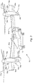
Figure 3 is a perspective view of a tiltrotor aircraft in helicopter mode; -
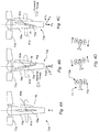
Figures 4A-C are side views of the rotor assembly as shown inFigure 3 ; with the wing extenses pivotably coupled to the nacelles (not claimed). -
Figure 4D is a top view of the tiltrotor aircraft as shown inFigure 3 ; -
Figure 5 is a perspective view of a quad-tiltrotor aircraft in airplane mode; -
Figure 6 is a side view of the quad-tiltrotor aircraft as shown inFigure 5 ; -
Figure 7A is a schematic, top view of the quad-tiltrotor aircraft as shown inFigure 6 ; and -
Figure 7B is a schematic, side view of the quad-tiltrotor aircraft as shown inFigure 6 . - While the invention is susceptible to various modifications and alternative forms, specific embodiments thereof have been shown by way of example in the drawings and are herein described in detail. It should be understood, however, that the description herein of specific embodiments is not intended to limit the invention to the particular forms disclosed, but on the contrary, the intention is to cover all modifications, equivalents, and alternatives falling within the spirit and scope of the invention as described herein.
- The present application discloses substantial improvements in the field of helicopters and other rotorcraft. The present application describes a rotatable wing extension that pivotally attaches to the outboard section of the aircraft's nacelle. The wing extension creates additional yaw control during helicopter mode and increases lift during airplane mode. The additional lift enables the aircraft to increase payload capacity.
- Illustrative embodiments are described below. In the interest of charity, not all features of an actual implementation are described in this specification. It will of course be appreciated that in the development of any such actual embodiment, numerous implementation-specific decisions will be made to achieve the developer's specific goals, such as compliance with system-related and business-related constraints, which will vary from one implementation to another. Moreover, it will be appreciated that such a development effort might be complex and time-consuming but would nevertheless be a routine undertaking for those of ordinary skill in the art having the benefit of this disclosure.
- Referring now to
Figures 1A and 1B in the drawings, a front view of a tiltwing aircraft (not climed) 11 is illustrated. InFigure 1A ,tiltwing aircraft 11 is shown in helicopter mode, whileFigure 1B shows tiltwingaircraft 11 in airplane mode. Tiltwingaircraft 11 includes afuselage 13 having anupper surface 15 pivotally attached to awing 17. Wing 17 rigidly attaches to twonacelles propellers wing 17 is positioned substantially perpendicular tofuselage 13. In airplane mode,wing 17 rotates about axis A to a position substantially parallel tofuselage 13. - Referring now to
Figures 2A and 2B in the drawings, a front view of a tiltrotor aircraft (not claimed) 31 is illustrated withrotatable wing sections Figure 2A showsaircraft 31 in helicopter mode, whileFigure 2B showsaircraft 31 in airplane mode.Tiltrotor aircraft 31 includes afuselage 35 rigidly attached to awing 37.Wing 37 includesrotatable wing sections fixed wing sections wing sections engine nacelles rotatable wing section respective engines Figure 2A ,rotatable wing sections wing 37 for vertical take-off and landing. As shown inFigure 2B ,rotatable wing sections wing 37 for horizontal flight. - Referring now to
Figure 3 in the drawings, a perspective view oftiltrotor aircraft 71 is illustrated.Tiltrotor aircraft 71 is shown in helicopter mode withrotor assemblies respective wing extensions nacelles inboard sections nacelles Fuselage 72 rigidly attaches to wing members 81A, 81B.Rotor assemblies rotor assemblies tiltrotor aircraft 71 flies like a conventional helicopter; and an airplane mode in whichrotor assemblies tiltrotor aircraft 71 flies like a conventional propeller-driven aircraft. - In some embodiments (not claimed),
wing extensions outboard sections Nacelles wing extensions wing extensions Figs. 4B, 4C ). A computer system or pilot could adjust the wing extension rotation to vary the magnitude of thrust, thereby controlling yaw movement. Yaw control is further discussed below in connection withFigures 4A-4D . Wing extension flaps 83a, 83b are pivotally coupled torespective wing extensions - Referring now to
Figures 4A-4D in the drawings,Figures 4A-4C illustrate side views ofrotor assembly 73a as shown inFigure 3 .Figure 4D illustrates a top view oftiltrotor aircraft 71 as shown inFigure 3 . InFigures 4A-4C ,rotor assembly 73a remains substantially perpendicular to wing 81A.Wing extension 75a is shown attached torotor assembly 73a in positions C, D, and E relative to the rotor's axis of rotation. In position C, awing extension chord 76 is aligns with the rotor axis of rotation; whereas,chord 76 does not align with the rotor axis of rotation in positions D andE. Joint 85a (not claimed) pivotally attacheswing extension 75a andnacelle 79a. It should be understood that some embodiments include joint 85a, while other embodiments could include any suitable device for attachingwing extension 75a tonacelle 79a. It should be appreciated that a hydraulic, motor, pneumatic, or any suitable device could be used to rotatewing extensions - In
Figure 4A (showing not claimed subject matter), rotor wash (not shown) from rotor 77A creates a downward force F on wing member 81A andwing extension 75a. This figure showswing extension 75a in position C, a position substantially perpendicular to wing 81A. In this position, no substantial horizontal force Fx from the rotor wash acts againstwing extension 75a; therefore, no forward or reverse thrust is produced by the rotor wash.Figure 4B showswing extension 75a in position D. In this position, the rotor wash creates a horizontal force Fx and a vertical force Fy onwing wing extension 75a, thereby creating a reverse thrust.Figure 4C showswing extension 75a in position E. In this position, the rotor wash creates a horizontal force Fx and a vertical force Fy onwing extension 75a, thereby creating a forward thrust. It should be understood that the wing extension's angle of rotation is not limited to positions C, D, and E. A pilot and/or flight control system could vary the magnitude of thrust by changing the angle of rotation. For example, if the wing extension is at position D, and less reverse thrust is desired, then the pilot and/or flight control system can adjust from position D to a position between D and C.Figure 4D shows a top view oftiltrotor aircraft 71 withrotor assemblies extensions extensions - Referring now to
Figure 5 in the drawings, a perspective view of a quad-tiltrotor aircraft 111 is illustrated. It should be understood that the present disclosure can be applied to many different types of tiltrotor aircrafts, including a quad-tiltrotor aircraft. Quad-tiltrotor aircraft are similar to conventional tiltrotor aircraft in that quad-tiltrotor aircraft include rotatable rotor assemblies for operating in helicopter and airplane modes. Quad-tiltrotor aircraft differ from a conventional tiltrotor aircraft in that a quad-tiltrotor aircraft includes four rotor assemblies and typically carry heavier payloads. As the payload increases, more wing surface area is required during airplane mode. Therefore, wing extensions are particularly desired because they increase the aircraft's wing surface area. - In the illustrated embodiment, quad-tiltrotor aircraft 111 includes four
wing extensions 113a-113d and fourwing extension flaps 115a-115d pivotally (not claimed) attached to the outboard sections of respective rotor assemblies 117A-117d. Rotor assemblies 117A-117d are pivotally coupled to fourrespective wings members 119a-119d. Rotor assemblies 117A-117d include four nacelles 121A-121d, which carry the engines and transmissions of quad-tiltrotor aircraft 111. Rotor assemblies 117A-117d also carryrespective rotor 123a-123d on forward ends of rotor assemblies 117A-117d, respectively. Rotor assemblies 117A-117d move or rotate relative torespective wing members 119a-119d between a helicopter mode, in which rotor assemblies 117A-117d are tilted upward such that quad-tiltrotor aircraft 111 flies like a conventional helicopter, and an airplane mode, in which rotor assemblies 117A-117d are tilted forward such that quad-tiltrotor aircraft 111 flies like a conventional propeller-driven aircraft. In helicopter mode,wing extensions 113a-113d move or rotate relative towing members 119a-119d, thereby providing additional yaw control. - The wing extensions provide quad-tiltrotor aircraft 111 additional yaw control (not claimed) during helicopter mode and additional lift during airplane mode. In airplane mode the wing extensions are positioned substantially parallel to the aircraft's wing members. In this position, the aircraft's overall wing surface area increases, thereby creating additional lift. The following aerodynamic equation helps in understanding this principal:

Figures 7A, 7B , respectively. - The tiltrotor of the present invention includes a flap pivotably coupled to the wing extension, providing additionnal yaw movement of the aircraft.
- Referring now to
Figure 6 in the drawings, a side view of quad-tiltrotor aircraft 111, as shown inFigure 5 , is illustrated. Joint 85c, 85dcouple wing extensions respective nacelles wing extensions - Referring now to
Figure 7A and 7B in the drawings, a schematic view of quad-tiltrotor aircraft 111, as shown inFigure 6 , is illustrated.Figure 7A shows a top, schematic view of quad-tiltrotor aircraft 111 carrying a plurality of passenger seats 131. Here, quad-tiltrotor aircraft 111 is configured for personnel transportation.Figure 7B shows a side, schematic view of quad-tiltrotor aircraft 111 carrying a plurality ofvehicles 133. Here, quad-tiltrotor aircraft 111 is configured for vehicular transportation. It should be understood thatFigures 7A, 7B are two among many embodiments of quad-tiltrotor aircraft 111. Quad-tiltrotor aircraft 111 could be designed in a myriad of alternative configurations. - The concepts of the present application are unique in that the present application introduces a rotatable wing extension for a tiltrotor aircraft. It is evident by the foregoing description that the subject application has significant benefits and advantages, in particular: (1) the wing extension provides additional wing surface area, which enables the aircraft to carry heavier payloads during airplane mode; and (2) during helicopter mode, the rotatable wing extension provides additional yaw control.
- It is apparent that an invention with significant advantages has been described and illustrated. The particular embodiments disclosed above are illustrative only, as the invention may be modified and practiced in different but equivalent manners apparent to those skilled in the art having the benefit of the teachings herein. It is therefore evident that the particular embodiments disclosed above may be altered or modified, and all such variations are considered within the scope and spirit of the invention. Accordingly, the protection sought herein is as set forth in the description. Although the present application is shown in a limited number of forms, it is not limited to just these forms, but is amenable to various changes and modifications without departing from the scope thereof.
Claims (6)
- A tiltrotor aircraft (71; 111), comprising:a fuselage (72);a nacelle (79a, 79b; 121a-d) comprising:an inboard section (78a, 78b) rotatably attached to the fuselage; andan outboard section (80a, 80b);a rotor assembly (73a, 73b; 113a-d) supported by the nacelle (79a, 79b; 121a-d);a wing extension (75a, 75b; 113a-d) rigidly coupled to the outboard section of the nacelle (79a, 79b; 121a-d) such that the wing extension (75a, 75b; 113a-d) rotates with the nacelle's (79a, 79b; 121 a-d) rotation; and characterized bya flap (83a, 83b; 115a-d) pivotally coupled to the wing extension (75a, 75b; 113 a-d);wherein the flap (83a, 83b; 115a-d) provides additional yaw movement of the aircraft (71; 111) during flight in helicopter mode
- The tiltrotor aircraft according to claim 1, wherein the tiltrotor aircraft is a quad-tiltrotor aircraft (111).
- The tiltrotor aircraft according to claim 2, wherein the quad-tiltrotor aircraft (111) comprises:two wing extensions (113a-d).
- The tiltrotor aircraft according to claim 2, wherein the quad-tiltrotor aircraft (111) comprises:four wing extensions (113a-d).
- A method for controlling yaw movement of a tiltrotor aircraft (71; 111), comprising:positioning a rotor assembly (73a, 73b; 117a-d) in a helicopter mode, the rotor assembly (73a, 73b; 117a-d) comprising:a nacelle (79a,b; 121a-d) having an outboard section (80a, 80b);a rotor (77a, 77b; 123a-d) carried by the nacelle (79a,b; 121 a-d);a wing extension (75a, 75b; 113a-d) rigidly attached to the outboard section of the nacelle (79a,b; 121a-d) such that the wing extension (75a, 75b; 113a-d) rotates with the nacelle's (79a, 79b; 121a-d) rotation; anda flap (83a, 83b; 115a-d) pivotally coupled to the wing extension (75a, 75b; 113a-d);rotating the rotor (77a, 77b; 123a-d) such that rotor wash is created; andpivotally rotating the flap (83a, 83b; 115a-d) of the wing extension (75a, 75b; 113a-d) in the rotorwash, thereby at least partially controlling yaw movement during flight in helicopter mode.
- The method according to claim 5, wherein the helicopter mode is achieved by positioning the nacelle (79a, 79b; 121a-d) in a position for vertical take-off and landing.
Applications Claiming Priority (1)
| Application Number | Priority Date | Filing Date | Title |
|---|---|---|---|
| PCT/US2009/036889 WO2010104509A1 (en) | 2009-03-12 | 2009-03-12 | Wing extension control surface |
Publications (3)
| Publication Number | Publication Date |
|---|---|
| EP2406131A1 EP2406131A1 (en) | 2012-01-18 |
| EP2406131A4 EP2406131A4 (en) | 2014-03-05 |
| EP2406131B1 true EP2406131B1 (en) | 2016-05-11 |
Family
ID=42728605
Family Applications (1)
| Application Number | Title | Priority Date | Filing Date |
|---|---|---|---|
| EP09841622.5A Active EP2406131B1 (en) | 2009-03-12 | 2009-03-12 | Tiltrotor aircraft and method of controlling yaw movement therefor |
Country Status (4)
| Country | Link |
|---|---|
| US (1) | US9102401B2 (en) |
| EP (1) | EP2406131B1 (en) |
| CA (1) | CA2754206C (en) |
| WO (1) | WO2010104509A1 (en) |
Families Citing this family (62)
| Publication number | Priority date | Publication date | Assignee | Title |
|---|---|---|---|---|
| US8794567B2 (en) * | 2007-05-08 | 2014-08-05 | Yigal Adir | Control and safety system for an airplane |
| CN102001446B (en) * | 2010-11-11 | 2013-08-28 | 韦斯豪 | Structure of vertical take-off and landing rotor aircraft |
| RU2492112C1 (en) * | 2012-04-19 | 2013-09-10 | Дмитрий Сергеевич Дуров | Heavy-duty multi-propeller converter plate |
| US9199721B2 (en) * | 2013-01-29 | 2015-12-01 | Gulfstream Aerospace Corporation | Wing flaps for aircraft and methods for making the same |
| SG10201806915VA (en) * | 2013-05-03 | 2018-09-27 | Aerovironment Inc | Vertical takeoff and landing (vtol) air vehicle |
| US20150175258A1 (en) * | 2013-12-20 | 2015-06-25 | Hung-Fu Lee | Helicopter with h-pattern structure |
| US9708059B2 (en) * | 2014-02-19 | 2017-07-18 | The United States Of America As Represented By The Adminstrator Of The National Aeronautics And Space Administration | Compound wing vertical takeoff and landing small unmanned aircraft system |
| US9694911B2 (en) * | 2014-03-18 | 2017-07-04 | Joby Aviation, Inc. | Aerodynamically efficient lightweight vertical take-off and landing aircraft with pivoting rotors and stowing rotor blades |
| US20150274289A1 (en) * | 2014-03-31 | 2015-10-01 | The Boeing Corporation | Vertically landing aircraft |
| US9481457B2 (en) * | 2014-04-02 | 2016-11-01 | Sikorsky Aircraft Corporation | Vertical take-off and landing aircraft with variable wing geometry |
| WO2015179346A1 (en) | 2014-05-23 | 2015-11-26 | Sikorsky Aircraft Corporation | Compliant engine nacelle for aircraft |
| CN105584629A (en) * | 2014-10-19 | 2016-05-18 | 吴建伟 | Aircraft capable of vertically taking off and landing |
| WO2016130847A1 (en) | 2015-02-11 | 2016-08-18 | Aerovironment, Inc. | Pod launch and landing system for vertical take-off and landing (vtol) unmanned aerial vehicles (uavs) |
| WO2016130711A1 (en) | 2015-02-11 | 2016-08-18 | Aerovironment, Inc. | Pod operating system for a vertical take-off and landing (vtol) unmanned aerial vehicle (uav) |
| WO2016130797A1 (en) * | 2015-02-11 | 2016-08-18 | Aerovironment, Inc. | Pod cover system for a vertical take-off and landing (vtol) unmanned aerial vehicle (uav) |
| WO2016130721A2 (en) | 2015-02-11 | 2016-08-18 | Aerovironment, Inc. | Survey migration system for vertical take-off and landing (vtol) unmanned aerial vehicles (uavs) |
| US9880563B2 (en) | 2015-02-11 | 2018-01-30 | Aerovironment, Inc. | Geographic survey system for vertical take-off and landing (VTOL) unmanned aerial vehicles (UAVs) |
| US10106274B2 (en) * | 2015-03-30 | 2018-10-23 | Sikorsky Aircraft Corporation | Tail sitter vehicle with aerial and ground refueling system |
| US20170174342A1 (en) * | 2015-06-12 | 2017-06-22 | Deng Huang | Vertical Takeoff Aircraft and Method |
| CN104925254A (en) * | 2015-06-24 | 2015-09-23 | 吴畏 | Vertical take-off and landing aircraft |
| WO2017049422A1 (en) * | 2015-09-24 | 2017-03-30 | 康坚 | Four-rotor aircraft with dynamical variations |
| US9958876B2 (en) * | 2016-07-27 | 2018-05-01 | Kitty Hawk Corporation | Flight configuration for payload and lift aircraft |
| US10011349B2 (en) | 2016-08-31 | 2018-07-03 | Bell Helicopter Textron Inc. | Tiltrotor aircraft having rotatable wing extensions |
| US10279892B2 (en) | 2016-08-31 | 2019-05-07 | Bell Helicopter Textron Inc. | Tiltrotor aircraft having active wing extensions |
| US10266252B2 (en) * | 2016-09-19 | 2019-04-23 | Bell Helicopter Textron Inc. | Wing extension winglets for tiltrotor aircraft |
| US10343762B2 (en) | 2016-09-21 | 2019-07-09 | Bell Helicopter Textron, Inc. | Fuselage mounted engine with wing stow |
| EP3299279B1 (en) * | 2016-09-21 | 2018-10-17 | Bell Helicopter Textron Inc. | Aircraft with a fuselage-mounted engine and wing stow |
| US10414483B2 (en) | 2016-09-21 | 2019-09-17 | Bell Helicopter Textron, Inc. | Tiltrotor articulated wing extension |
| CN106184737B (en) * | 2016-09-23 | 2017-06-23 | 西北工业大学 | Combined type is laid out vertically taking off and landing flyer and VTOL flying method |
| US11208207B2 (en) * | 2016-10-31 | 2021-12-28 | Textron Innovations Inc. | Vertical takeoff and landing (VTOL) aircraft |
| US10570931B2 (en) * | 2017-03-22 | 2020-02-25 | Textron Innovations Inc. | Aircraft hydraulic systems having shared components |
| US20190106197A1 (en) * | 2017-10-09 | 2019-04-11 | Bell Helicopter Textron Inc. | Variable-Chord Rotor Blade |
| US12043377B2 (en) * | 2018-01-30 | 2024-07-23 | Joseph Raymond RENTERIA | Rotatable thruster aircraft |
| US11148805B2 (en) * | 2018-04-10 | 2021-10-19 | Government Of The United States, As Represented By The Secretary Of The Army | Enclosure for an unmanned aerial system |
| CN121553374A (en) | 2018-05-31 | 2026-02-24 | 杰欧比飞行有限公司 | Electric power system architecture and fault tolerant VTOL aircraft using the same |
| US12006048B2 (en) | 2018-05-31 | 2024-06-11 | Joby Aero, Inc. | Electric power system architecture and fault tolerant VTOL aircraft using same |
| JP7130064B2 (en) | 2018-06-01 | 2022-09-02 | ジョビー エアロ,インコーポレイテッド | Aircraft noise abatement system and method |
| US11148798B2 (en) * | 2018-06-22 | 2021-10-19 | Textron Innovations Inc. | Engine and rotatable proprotor configurations for a tiltrotor aircraft |
| US10710741B2 (en) | 2018-07-02 | 2020-07-14 | Joby Aero, Inc. | System and method for airspeed determination |
| US10913542B2 (en) * | 2018-07-27 | 2021-02-09 | Textron Innovations Inc. | Conversion actuator and downstop striker fitting for a tiltrotor aircraft |
| US10994839B2 (en) | 2018-07-31 | 2021-05-04 | Textron Innovations Inc. | System and method for rotating a rotor of a tiltrotor aircraft |
| US20200086971A1 (en) * | 2018-09-14 | 2020-03-19 | Bell Helicopter Textron Inc. | Tiltrotor Free-Pivot Wing Extension |
| EP3853736B1 (en) | 2018-09-17 | 2025-10-22 | Joby Aero, Inc. | Aircraft control system |
| EP3891067B1 (en) | 2018-12-07 | 2024-01-17 | Joby Aero, Inc. | Aircraft control system and method |
| JP7401545B2 (en) | 2018-12-07 | 2023-12-19 | ジョビー エアロ インク | Rotor blades and their design methods |
| EP3899427B1 (en) | 2018-12-19 | 2025-09-03 | Joby Aero, Inc. | Vehicle navigation system |
| CN114041229B (en) | 2019-04-23 | 2023-06-16 | 杰欧比飞行有限公司 | Battery thermal management system and method |
| US11230384B2 (en) | 2019-04-23 | 2022-01-25 | Joby Aero, Inc. | Vehicle cabin thermal management system and method |
| CN114423679A (en) | 2019-04-25 | 2022-04-29 | 杰欧比飞行有限公司 | Vertical take-off and landing aircraft |
| US11873078B2 (en) | 2019-05-20 | 2024-01-16 | The Boeing Company | Aircraft nacelles having adjustable chines |
| US11591097B2 (en) | 2019-05-20 | 2023-02-28 | The Boeing Company | Aircraft nacelles having adjustable chines |
| US11745860B2 (en) | 2019-05-20 | 2023-09-05 | The Boeing Company | Aircraft nacelles having adjustable chines |
| US20200369377A1 (en) * | 2019-05-20 | 2020-11-26 | The Boeing Company | Aircraft nacelles having adjustable chines |
| US11613345B2 (en) | 2019-05-20 | 2023-03-28 | The Boeing Company | Aircraft nacelles having adjustable chines |
| US11535362B2 (en) | 2019-05-20 | 2022-12-27 | The Boeing Company | Aircraft nacelles having adjustable chines |
| US11279478B2 (en) * | 2019-06-18 | 2022-03-22 | Textron Innovations Inc. | Tilting closed-wing aircraft |
| US10730635B1 (en) * | 2019-08-23 | 2020-08-04 | Raytheon Technologies Corporation | Engine wing |
| US11738862B2 (en) | 2020-01-28 | 2023-08-29 | Overair, Inc. | Fail-operational vtol aircraft |
| US11465738B2 (en) * | 2020-01-28 | 2022-10-11 | Overair, Inc. | Fail-operational VTOL aircraft |
| EP4291489A1 (en) * | 2021-02-09 | 2023-12-20 | Joby Aero, Inc. | Aircraft propulsion unit |
| WO2023200852A1 (en) * | 2022-04-14 | 2023-10-19 | Overair Inc. | Stall-resistant outboard wing for aircraft |
| CN115503951A (en) * | 2022-11-10 | 2022-12-23 | 魏晶晶 | Tilt wing aircraft fuselage layout and wing tilting mechanism |
Family Cites Families (11)
| Publication number | Priority date | Publication date | Assignee | Title |
|---|---|---|---|---|
| US1846992A (en) | 1931-05-05 | 1932-02-23 | Decker Virgil Cecil | Four winged aeroplane |
| US3181810A (en) * | 1961-02-27 | 1965-05-04 | Curtiss Wright Corp | Attitude control system for vtol aircraft |
| US3107882A (en) * | 1962-08-10 | 1963-10-22 | Electric Auto Lite Co | Yaw control system for vtol tilt wing aircraft |
| US3666209A (en) | 1970-02-24 | 1972-05-30 | Boeing Co | V/stol aircraft with variable tilt wing |
| DE3929886A1 (en) | 1989-09-08 | 1991-03-28 | Dornier Conrado | AIRPLANE WITH ENGINE GONDOLAS TILTABLE ABOVE A CROSS AXLE |
| US5141176A (en) * | 1991-06-12 | 1992-08-25 | Grumman Aerospace Corporation | Tilt wing VTOL aircraft |
| IT1308096B1 (en) | 1999-06-02 | 2001-11-29 | Finmeccanica Spa | TILTROTOR |
| FR2798359B1 (en) | 1999-09-14 | 2001-11-09 | Eurocopter France | IMPROVEMENTS ON TILTING ROTOR CONVERTIBLE AIRCRAFT |
| EP2182240B1 (en) * | 2002-09-24 | 2014-08-06 | Bell Helicopter Textron Inc. | A method of controlling the acoustic radiation of a ship |
| US7802754B2 (en) | 2005-08-15 | 2010-09-28 | Abe Karem | Tilt outboard wing for tilt rotor aircraft |
| KR101125870B1 (en) * | 2011-07-29 | 2012-03-28 | 한국항공우주연구원 | The tiltrotor aircraft |
-
2009
- 2009-03-12 WO PCT/US2009/036889 patent/WO2010104509A1/en not_active Ceased
- 2009-03-12 US US13/255,268 patent/US9102401B2/en active Active
- 2009-03-12 EP EP09841622.5A patent/EP2406131B1/en active Active
- 2009-03-12 CA CA2754206A patent/CA2754206C/en active Active
Non-Patent Citations (1)
| Title |
|---|
| None * |
Also Published As
| Publication number | Publication date |
|---|---|
| CA2754206A1 (en) | 2010-09-16 |
| US20110315827A1 (en) | 2011-12-29 |
| WO2010104509A1 (en) | 2010-09-16 |
| CA2754206C (en) | 2019-04-09 |
| US9102401B2 (en) | 2015-08-11 |
| EP2406131A4 (en) | 2014-03-05 |
| EP2406131A1 (en) | 2012-01-18 |
Similar Documents
| Publication | Publication Date | Title |
|---|---|---|
| CA2754206C (en) | Wing extension control surface | |
| EP2265495B1 (en) | Coaxial rotor aircraft | |
| US8864062B2 (en) | Aircraft with integrated lift and propulsion system | |
| EP2421752B1 (en) | Aircraft with integrated lift and propulsion system | |
| US8800912B2 (en) | Three wing, six-tilt propulsion unit, VTOL aircraft | |
| US8708273B2 (en) | Three-wing, six tilt-propulsion unit, VTOL aircraft | |
| EP2595882B1 (en) | Personal aircraft | |
| EP2242684B1 (en) | Rotorcraft with variable incident wing | |
| US9205919B1 (en) | Apparatus and method for roll moment equalization at high advance ratios for rotary wing aircraft | |
| JP2020534212A (en) | Wing tilt actuation system for electric vertical takeoff and landing (VTOL) aircraft | |
| US10737776B2 (en) | Apparatus and method for roll moment equalization at high advance ratios for rotary wing aircraft | |
| US6607161B1 (en) | Convertible aircraft with tilting rotors | |
| WO2018217667A1 (en) | Evtol aircraft using large, variable speed tilt rotors | |
| WO2008085192A2 (en) | Rotorcraft with opposing roll mast moments, and related methods | |
| EP2625094A1 (en) | Three wing, six tilt-propulsion unit, vtol aircraft | |
| EP3385161B1 (en) | Teetering tail rotor yoke | |
| US20240228031A9 (en) | Hybrid Tilt Propeller/Tilt Wing Aircraft | |
| CZ2023513A3 (en) | Aircraft for vertical take-off and landing and forward flight |
Legal Events
| Date | Code | Title | Description |
|---|---|---|---|
| PUAI | Public reference made under article 153(3) epc to a published international application that has entered the european phase |
Free format text: ORIGINAL CODE: 0009012 |
|
| 17P | Request for examination filed |
Effective date: 20110914 |
|
| AK | Designated contracting states |
Kind code of ref document: A1 Designated state(s): AT BE BG CH CY CZ DE DK EE ES FI FR GB GR HR HU IE IS IT LI LT LU LV MC MK MT NL NO PL PT RO SE SI SK TR |
|
| DAX | Request for extension of the european patent (deleted) | ||
| A4 | Supplementary search report drawn up and despatched |
Effective date: 20140204 |
|
| RIC1 | Information provided on ipc code assigned before grant |
Ipc: B64C 27/22 20060101AFI20140129BHEP |
|
| 17Q | First examination report despatched |
Effective date: 20141017 |
|
| GRAP | Despatch of communication of intention to grant a patent |
Free format text: ORIGINAL CODE: EPIDOSNIGR1 |
|
| GRAS | Grant fee paid |
Free format text: ORIGINAL CODE: EPIDOSNIGR3 |
|
| INTG | Intention to grant announced |
Effective date: 20160222 |
|
| GRAA | (expected) grant |
Free format text: ORIGINAL CODE: 0009210 |
|
| AK | Designated contracting states |
Kind code of ref document: B1 Designated state(s): AT BE BG CH CY CZ DE DK EE ES FI FR GB GR HR HU IE IS IT LI LT LU LV MC MK MT NL NO PL PT RO SE SI SK TR |
|
| REG | Reference to a national code |
Ref country code: GB Ref legal event code: FG4D |
|
| REG | Reference to a national code |
Ref country code: CH Ref legal event code: EP |
|
| REG | Reference to a national code |
Ref country code: AT Ref legal event code: REF Ref document number: 798435 Country of ref document: AT Kind code of ref document: T Effective date: 20160515 |
|
| REG | Reference to a national code |
Ref country code: IE Ref legal event code: FG4D |
|
| REG | Reference to a national code |
Ref country code: DE Ref legal event code: R096 Ref document number: 602009038673 Country of ref document: DE |
|
| REG | Reference to a national code |
Ref country code: LT Ref legal event code: MG4D |
|
| REG | Reference to a national code |
Ref country code: NL Ref legal event code: MP Effective date: 20160511 |
|
| PG25 | Lapsed in a contracting state [announced via postgrant information from national office to epo] |
Ref country code: NL Free format text: LAPSE BECAUSE OF FAILURE TO SUBMIT A TRANSLATION OF THE DESCRIPTION OR TO PAY THE FEE WITHIN THE PRESCRIBED TIME-LIMIT Effective date: 20160511 Ref country code: LT Free format text: LAPSE BECAUSE OF FAILURE TO SUBMIT A TRANSLATION OF THE DESCRIPTION OR TO PAY THE FEE WITHIN THE PRESCRIBED TIME-LIMIT Effective date: 20160511 Ref country code: NO Free format text: LAPSE BECAUSE OF FAILURE TO SUBMIT A TRANSLATION OF THE DESCRIPTION OR TO PAY THE FEE WITHIN THE PRESCRIBED TIME-LIMIT Effective date: 20160811 Ref country code: FI Free format text: LAPSE BECAUSE OF FAILURE TO SUBMIT A TRANSLATION OF THE DESCRIPTION OR TO PAY THE FEE WITHIN THE PRESCRIBED TIME-LIMIT Effective date: 20160511 |
|
| REG | Reference to a national code |
Ref country code: AT Ref legal event code: MK05 Ref document number: 798435 Country of ref document: AT Kind code of ref document: T Effective date: 20160511 |
|
| PG25 | Lapsed in a contracting state [announced via postgrant information from national office to epo] |
Ref country code: PT Free format text: LAPSE BECAUSE OF FAILURE TO SUBMIT A TRANSLATION OF THE DESCRIPTION OR TO PAY THE FEE WITHIN THE PRESCRIBED TIME-LIMIT Effective date: 20160912 Ref country code: LV Free format text: LAPSE BECAUSE OF FAILURE TO SUBMIT A TRANSLATION OF THE DESCRIPTION OR TO PAY THE FEE WITHIN THE PRESCRIBED TIME-LIMIT Effective date: 20160511 Ref country code: HR Free format text: LAPSE BECAUSE OF FAILURE TO SUBMIT A TRANSLATION OF THE DESCRIPTION OR TO PAY THE FEE WITHIN THE PRESCRIBED TIME-LIMIT Effective date: 20160511 Ref country code: SE Free format text: LAPSE BECAUSE OF FAILURE TO SUBMIT A TRANSLATION OF THE DESCRIPTION OR TO PAY THE FEE WITHIN THE PRESCRIBED TIME-LIMIT Effective date: 20160511 Ref country code: GR Free format text: LAPSE BECAUSE OF FAILURE TO SUBMIT A TRANSLATION OF THE DESCRIPTION OR TO PAY THE FEE WITHIN THE PRESCRIBED TIME-LIMIT Effective date: 20160812 Ref country code: ES Free format text: LAPSE BECAUSE OF FAILURE TO SUBMIT A TRANSLATION OF THE DESCRIPTION OR TO PAY THE FEE WITHIN THE PRESCRIBED TIME-LIMIT Effective date: 20160511 |
|
| PG25 | Lapsed in a contracting state [announced via postgrant information from national office to epo] |
Ref country code: DK Free format text: LAPSE BECAUSE OF FAILURE TO SUBMIT A TRANSLATION OF THE DESCRIPTION OR TO PAY THE FEE WITHIN THE PRESCRIBED TIME-LIMIT Effective date: 20160511 Ref country code: SK Free format text: LAPSE BECAUSE OF FAILURE TO SUBMIT A TRANSLATION OF THE DESCRIPTION OR TO PAY THE FEE WITHIN THE PRESCRIBED TIME-LIMIT Effective date: 20160511 Ref country code: RO Free format text: LAPSE BECAUSE OF FAILURE TO SUBMIT A TRANSLATION OF THE DESCRIPTION OR TO PAY THE FEE WITHIN THE PRESCRIBED TIME-LIMIT Effective date: 20160511 Ref country code: EE Free format text: LAPSE BECAUSE OF FAILURE TO SUBMIT A TRANSLATION OF THE DESCRIPTION OR TO PAY THE FEE WITHIN THE PRESCRIBED TIME-LIMIT Effective date: 20160511 Ref country code: CZ Free format text: LAPSE BECAUSE OF FAILURE TO SUBMIT A TRANSLATION OF THE DESCRIPTION OR TO PAY THE FEE WITHIN THE PRESCRIBED TIME-LIMIT Effective date: 20160511 |
|
| REG | Reference to a national code |
Ref country code: DE Ref legal event code: R097 Ref document number: 602009038673 Country of ref document: DE |
|
| PG25 | Lapsed in a contracting state [announced via postgrant information from national office to epo] |
Ref country code: AT Free format text: LAPSE BECAUSE OF FAILURE TO SUBMIT A TRANSLATION OF THE DESCRIPTION OR TO PAY THE FEE WITHIN THE PRESCRIBED TIME-LIMIT Effective date: 20160511 Ref country code: PL Free format text: LAPSE BECAUSE OF FAILURE TO SUBMIT A TRANSLATION OF THE DESCRIPTION OR TO PAY THE FEE WITHIN THE PRESCRIBED TIME-LIMIT Effective date: 20160511 Ref country code: BE Free format text: LAPSE BECAUSE OF FAILURE TO SUBMIT A TRANSLATION OF THE DESCRIPTION OR TO PAY THE FEE WITHIN THE PRESCRIBED TIME-LIMIT Effective date: 20160511 |
|
| PLBE | No opposition filed within time limit |
Free format text: ORIGINAL CODE: 0009261 |
|
| STAA | Information on the status of an ep patent application or granted ep patent |
Free format text: STATUS: NO OPPOSITION FILED WITHIN TIME LIMIT |
|
| REG | Reference to a national code |
Ref country code: FR Ref legal event code: PLFP Year of fee payment: 9 |
|
| 26N | No opposition filed |
Effective date: 20170214 |
|
| PG25 | Lapsed in a contracting state [announced via postgrant information from national office to epo] |
Ref country code: SI Free format text: LAPSE BECAUSE OF FAILURE TO SUBMIT A TRANSLATION OF THE DESCRIPTION OR TO PAY THE FEE WITHIN THE PRESCRIBED TIME-LIMIT Effective date: 20160511 |
|
| REG | Reference to a national code |
Ref country code: CH Ref legal event code: PL |
|
| PG25 | Lapsed in a contracting state [announced via postgrant information from national office to epo] |
Ref country code: MC Free format text: LAPSE BECAUSE OF FAILURE TO SUBMIT A TRANSLATION OF THE DESCRIPTION OR TO PAY THE FEE WITHIN THE PRESCRIBED TIME-LIMIT Effective date: 20160511 |
|
| REG | Reference to a national code |
Ref country code: IE Ref legal event code: MM4A |
|
| PG25 | Lapsed in a contracting state [announced via postgrant information from national office to epo] |
Ref country code: LU Free format text: LAPSE BECAUSE OF NON-PAYMENT OF DUE FEES Effective date: 20170312 |
|
| PG25 | Lapsed in a contracting state [announced via postgrant information from national office to epo] |
Ref country code: LI Free format text: LAPSE BECAUSE OF NON-PAYMENT OF DUE FEES Effective date: 20170331 Ref country code: IE Free format text: LAPSE BECAUSE OF NON-PAYMENT OF DUE FEES Effective date: 20170312 Ref country code: CH Free format text: LAPSE BECAUSE OF NON-PAYMENT OF DUE FEES Effective date: 20170331 |
|
| REG | Reference to a national code |
Ref country code: FR Ref legal event code: PLFP Year of fee payment: 10 |
|
| PG25 | Lapsed in a contracting state [announced via postgrant information from national office to epo] |
Ref country code: MT Free format text: LAPSE BECAUSE OF NON-PAYMENT OF DUE FEES Effective date: 20170312 |
|
| PG25 | Lapsed in a contracting state [announced via postgrant information from national office to epo] |
Ref country code: HU Free format text: LAPSE BECAUSE OF FAILURE TO SUBMIT A TRANSLATION OF THE DESCRIPTION OR TO PAY THE FEE WITHIN THE PRESCRIBED TIME-LIMIT; INVALID AB INITIO Effective date: 20090312 |
|
| PG25 | Lapsed in a contracting state [announced via postgrant information from national office to epo] |
Ref country code: BG Free format text: LAPSE BECAUSE OF FAILURE TO SUBMIT A TRANSLATION OF THE DESCRIPTION OR TO PAY THE FEE WITHIN THE PRESCRIBED TIME-LIMIT Effective date: 20160511 |
|
| PG25 | Lapsed in a contracting state [announced via postgrant information from national office to epo] |
Ref country code: CY Free format text: LAPSE BECAUSE OF NON-PAYMENT OF DUE FEES Effective date: 20160511 |
|
| PG25 | Lapsed in a contracting state [announced via postgrant information from national office to epo] |
Ref country code: MK Free format text: LAPSE BECAUSE OF FAILURE TO SUBMIT A TRANSLATION OF THE DESCRIPTION OR TO PAY THE FEE WITHIN THE PRESCRIBED TIME-LIMIT Effective date: 20160511 |
|
| PG25 | Lapsed in a contracting state [announced via postgrant information from national office to epo] |
Ref country code: TR Free format text: LAPSE BECAUSE OF FAILURE TO SUBMIT A TRANSLATION OF THE DESCRIPTION OR TO PAY THE FEE WITHIN THE PRESCRIBED TIME-LIMIT Effective date: 20160511 |
|
| PG25 | Lapsed in a contracting state [announced via postgrant information from national office to epo] |
Ref country code: IS Free format text: LAPSE BECAUSE OF FAILURE TO SUBMIT A TRANSLATION OF THE DESCRIPTION OR TO PAY THE FEE WITHIN THE PRESCRIBED TIME-LIMIT Effective date: 20160911 |
|
| PGFP | Annual fee paid to national office [announced via postgrant information from national office to epo] |
Ref country code: DE Payment date: 20230329 Year of fee payment: 15 |
|
| P01 | Opt-out of the competence of the unified patent court (upc) registered |
Effective date: 20230602 |
|
| REG | Reference to a national code |
Ref country code: DE Ref legal event code: R119 Ref document number: 602009038673 Country of ref document: DE |
|
| PG25 | Lapsed in a contracting state [announced via postgrant information from national office to epo] |
Ref country code: DE Free format text: LAPSE BECAUSE OF NON-PAYMENT OF DUE FEES Effective date: 20241001 |
|
| PG25 | Lapsed in a contracting state [announced via postgrant information from national office to epo] |
Ref country code: DE Free format text: LAPSE BECAUSE OF NON-PAYMENT OF DUE FEES Effective date: 20241001 |
|
| PGFP | Annual fee paid to national office [announced via postgrant information from national office to epo] |
Ref country code: GB Payment date: 20260327 Year of fee payment: 18 |
|
| PGFP | Annual fee paid to national office [announced via postgrant information from national office to epo] |
Ref country code: IT Payment date: 20260319 Year of fee payment: 18 |
|
| PGFP | Annual fee paid to national office [announced via postgrant information from national office to epo] |
Ref country code: FR Payment date: 20260325 Year of fee payment: 18 |