EP2405455A1 - Switch - Google Patents
Switch Download PDFInfo
- Publication number
- EP2405455A1 EP2405455A1 EP11169774A EP11169774A EP2405455A1 EP 2405455 A1 EP2405455 A1 EP 2405455A1 EP 11169774 A EP11169774 A EP 11169774A EP 11169774 A EP11169774 A EP 11169774A EP 2405455 A1 EP2405455 A1 EP 2405455A1
- Authority
- EP
- European Patent Office
- Prior art keywords
- contact
- piece
- movable contact
- always
- operating element
- Prior art date
- Legal status (The legal status is an assumption and is not a legal conclusion. Google has not performed a legal analysis and makes no representation as to the accuracy of the status listed.)
- Granted
Links
Images


Classifications
-
- H—ELECTRICITY
- H01—ELECTRIC ELEMENTS
- H01H—ELECTRIC SWITCHES; RELAYS; SELECTORS; EMERGENCY PROTECTIVE DEVICES
- H01H13/00—Switches having rectilinearly-movable operating part or parts adapted for pushing or pulling in one direction only, e.g. push-button switch
- H01H13/02—Details
- H01H13/12—Movable parts; Contacts mounted thereon
- H01H13/14—Operating parts, e.g. push-button
- H01H13/18—Operating parts, e.g. push-button adapted for actuation at a limit or other predetermined position in the path of a body, the relative movement of switch and body being primarily for a purpose other than the actuation of the switch, e.g. door switch, limit switch, floor-levelling switch of a lift
-
- H—ELECTRICITY
- H01—ELECTRIC ELEMENTS
- H01H—ELECTRIC SWITCHES; RELAYS; SELECTORS; EMERGENCY PROTECTIVE DEVICES
- H01H3/00—Mechanisms for operating contacts
- H01H3/60—Mechanical arrangements for preventing or damping vibration or shock
-
- H—ELECTRICITY
- H01—ELECTRIC ELEMENTS
- H01H—ELECTRIC SWITCHES; RELAYS; SELECTORS; EMERGENCY PROTECTIVE DEVICES
- H01H13/00—Switches having rectilinearly-movable operating part or parts adapted for pushing or pulling in one direction only, e.g. push-button switch
- H01H13/02—Details
- H01H13/26—Snap-action arrangements depending upon deformation of elastic members
- H01H13/28—Snap-action arrangements depending upon deformation of elastic members using compression or extension of coil springs
Definitions
- the present invention relates to switches, and in particular, to a micro-switch capable of inhibiting the occurrence of resonance phenomenon and preventing false operation.
- the switch may be a brake lever interlocking switch including a switch case, a swing plate attached to the switch case to swing interlocking with the brake lever, a plurality of push rods that is attached to the switch case to push down with the swing plate and that has different distances from the center of rotation of the swing plate, and a switch means facing such push rods (see Japanese Unexamined Patent Publication No. 10-297364 )
- the amplitude of a spring 99 or a spring member increases by the vibration generated when opening and closing the contact or the impact force applied from the outside, and the resonance phenomenon tends to easily occur, as shown in Fig. 8 thereof.
- the resonance phenomenon occurs, not only does false operation occur, but the spring member easily breaks, the contact wears, and the contact lifespan becomes short.
- the present invention has been devised to solve the problems described above, and an object thereof is to provide a switch capable of inhibiting the occurrence of the resonance phenomenon caused by the increase of the amplitude of the spring member and preventing false operation, and furthermore, preventing the breakage of the spring member and realizing long contact lifespan.
- the spring member when the contact mechanism is operated with the operating element or when the impact force is applied from the outside, the spring member is not brought into contact with the regulating means if the spring member is not vibrating, whereas the spring member is brought into contact with the regulating means if the spring member is vibrating, particularly, if the spring member starts to vibrate.
- the regulating means shifts the timing to increase the amplitude of the spring member so that the amplitude of the spring member does not increase and the resonance phenomenon can be inhibited. Therefore, the false operation can be prevented, and furthermore, the breakage of the spring member can be prevented and the wear of the contact can be reduced so that a switch of longer contact lifespan can be realized.
- the spring member may be a coil member. According to such aspect, a switch having a large degree of freedom of design can be realized since the elastic displacement amount of the coil spring is large.
- the spring member may be a plate spring integral with the movable contact piece. According to such aspect, a switch with less number of components and number of assembly steps and with high productivity can be obtained.
- the spring member may be a plate spring of a separate body from the movable contact piece. According to such aspect, a switch having a large degree of freedom of design can be realized by using the plate spring of a separate body.
- the regulating means may be a tongue piece cutout from a terminal of the contact mechanism. According to such aspect, a switch with less number of components and number of assembly steps and with high productivity can be obtained.
- the regulating means may be a projection arranged in a projecting manner on the inner surface of the housing or a bulging portion bulging out from the inner surface of the housing.
- a switch with high productivity can be obtained by integrally molding the regulating means at the same time as the housing.
- the projection or the bulging portion may be assembled after being molded separate from the housing rather than being integrally molded on the inner surface of the housing.
- FIGS. 1A, 1B, and 1C are perspective views showing a first embodiments of a switch according to the present invention
- a switch according to a first embodiment is configured by a housing 10, an operating element 20 attached to the housing 10 through a rubber cap 25, and a contact mechanism 30 assembled to a holder 31 incorporated in the housing 10 from the side and operated by the operating element 20.
- the housing 10 includes an attachment hole 11b at a side surface of a step portion 11 a arranged on one side of a one side surface of a housing main body 11, and has a positioning boss 11c arranged in a projecting manner on the other side.
- the housing main body 11 includes a vertically long assembly opening 11d at the end face on the other side.
- the housing main body 11 has an operation hole 11f arranged between a pair of protection barriers 11e, 11e arranged in a projecting manner to the other side of the upper end face ( Fig. 2 ).
- the operating element 20 is assembled to the operation hole 11f of the housing 10 so as to be movable up and down by fitting an annular edge of an opening 26 of the rubber cap 25 to an annular groove 21 a formed on the upper side.
- a slip-out preventing projection 21 b is projected to the side at the outer peripheral surface on the lower side of the operating element 20 ( Fig. 3 ).
- the contact mechanism 30 has a common terminal 50 arranged between an always-opened fixed contact terminal 40 and an always-closed fixed contact terminal 45 assembled to the holder 31.
- An always-opened fixed contact 40a and an always-closed fixed contact 45a are respectively arranged at one end of the always-opened fixed contact terminal 40 and the always-closed fixed contact terminal 45.
- a movable contact piece 60, a coil spring 70 serving as a spring member, and an operation piece 80 are assembled to the common terminal 50.
- the holder 31 has an outer peripheral shape that can be inserted from an assembly opening 11d of the housing 10, and has press-fit slits 32a, 32b, 32c alternately arranged in a zigzag manner on a vertical wall 32.
- a pair of guide projections 32d, 32d is arranged on an inward surface of the vertical wall 32 to position regulate the operating element 20, to be described later.
- the common terminal 50 has a pair of raised pieces 51, 51 formed by cutting and raising both side edges on one side.
- the raised piece 51 has a cutout 51 a formed at the upper end and has a lock receiving portion 51 b formed at the outward edge of the raised piece 51.
- the common terminal 50 has a tongue piece 51 c cut and raised between the raised pieces 51. Furthermore, the common terminal 50 incudes a lock hole 51d in the vicinity of the tongue piece 51c.
- the tongue piece 51 c prevents resonance of the coil spring 70 by bringing a bent portion formed by bending the distal end edge to the lower side into contact with the lower surface of the coil spring 70 to be described later.
- the bent portion may have a shape that not only point contacts the coil spring 70, but also line contacts or area contacts thereto.
- the coil spring 70 can be reliably brought into contact with the bent portion even if the dimensional accuracy and the assembly accuracy of the components vary, so that the amplification of the amplitude of the coil spring 70 can be more reliably prevented.
- the movable contact piece 60 is a conductive plate spring having a substantially U-shape, where a movable contact 61 a is arranged at one end and a lock portion 61b that becomes a supporting point of turn is formed at both ends on the other end side.
- the movable contact piece 60 also includes a lock hole 61 c in the vicinity of the movable contact 61 a.
- the coil spring 70 has one end 71 a lockable to the lock hole 61 c of the movable contact piece 60 and the other end 71 b lockable to the lock hole 51 d of the common terminal 50.
- the operation piece 80 has an engagement shaft portion 81 a formed along the edge on one side, and a slip-out preventing projection 81 b that engages the cutout 51a of the raised piece 51 arranged to project to the side at both side edges of the intermediate portion.
- the operation piece 80 has a lock receiving portion 81d arranged at a distal end of an arm portion 81c bent down from both side edges on the other side, and has the other end serving as an operation receiving portion 81e.
- the one end 71 a of the coil spring 70 shown in Fig. 2 is locked to the lock hole 61 c of the movable contact piece 60, and the other end 71 b is locked to the lock hole 51 d of the common terminal 50.
- the slip-out preventing projection 81 b of the operation piece 80 is engaged to the cutout 51 a of the common terminal 50, and thereafter the engagement shaft portion 81 a of the operation piece 80 is engaged to the lock receiving portion 51 b of the common terminal 50 and the lock portion 61 b of the movable contact piece 60 is locked to lock receiving portion 81 d formed in the arm portion 81c.
- the movable contact piece 60 is thereby biased towards the lower side by the spring force of the coil spring 70.
- the common terminal 50 shown in Fig. 2 is press fit and positioned in the slit 32a of the holder 31, and the always-closed fixed contact terminal 45, the always-opened fixed contact terminal 40 are press fit to the slits 32b, 32c, respectively.
- the movable contact 61 a faces the always-closed fixed contact 45a and the always-opened fixed contact 40a so as to approach or separate thereto.
- the holder 31 After inserting the holder 31 from the opening 11 d of the housing 10, it is shielded with a resin mold.
- the opening edge on the lower side of the rubber cap 25 is fitted and thermally caulked to the opening edge of the operation hole 11f of the housing 10, and then the operating element 20 is press fit from the opening 26 of the rubber cap 25 and the opening edge of the rubber cap 25 is elastically fitted and sealed to the annular groove 21 a of the operating element 20.
- the operation receiving portion 81e of the operation piece 80 is biased to the upper side by the spring force of the coil spring 70 and the operating element 20 is also biased to the upper side in the no-load state.
- the operating element 20 does not slip out since the slip-out preventing projection 21b is locked to the top surface of the housing 10.
- the movable contact 61a is brought into contact with the always-closed fixed contact 45a and separated from the always-opened fixed contact 40a.
- the movable contact piece 60 When the pushing force with respect to the operating element 20 is released, the movable contact piece 60 is turned in the reverse direction with the spring force of the coil spring 70, and the operating element 20 is pushed to the upper side. Thus, the movable contact 61 a is switched from the always-opened fixed contact 40a to the always-closed fixed contact 45a to return to the original position.
- the operating element 20 does not move out from the housing 10 since the slip-out preventing projection 21 b locks to the top surface of the housing 10.
- the switch according to the second embodiment is configured by the housing 10, the operating element 20 attached to the housing 10, and the contact mechanism 30 incorporated in the housing 10 and operated by the operating element 20.
- the housing 10 is configured by a base 12 in which the always-opened fixed contact terminal 40, the always-closed fixed contact terminal 45, and the common terminal 50 are insert molded, and a cover 13 having a planar shape that can be fitted to the base 12.
- the contact mechanism 30 is configured by the always-opened fixed contact terminal 40, the always-closed fixed contact terminal 45, the common terminal 50, and the movable contact piece 60, to be described later.
- the base 12 has the always-opened fixed contact terminal 40 and the always-closed fixed contact terminal 45 projected from the upper surface, where the always-opened fixed contact 40a and the always-closed fixed contact 45a are respectively arranged at the upper end, the always-opened fixed contact 40a and the always-closed fixed contact 45a being faced to each other.
- the base has a pair of projection pieces 52, 52 of the common terminal 50 projecting out at the upper surface, where lock receiving portions 52a, 52b are arranged at the outer side edge of the projection pieces 52, 52.
- the base 12 has an engagement nail portion12a formed on both side surfaces facing each other.
- the cover 13 has a recessed area 13b for attaching the operation lever (not shown) formed in the vicinity of the operation hole 13a formed at the upper surface.
- the cover 13 has an engagement hole 13c formed at the corner on the lower side of the opposing side surface.
- the cover 13 has a projection 13d for position regulating a plate spring 72, to be described later, arranged in a projecting manner at the top surface.
- the movable contact piece 60 configuring the contact mechanism 30 is formed by performing press work on a conductive plate spring material, where a movable contact 62a is arranged on the end on the near side, and a fit-in hole 62b is formed on the far side. Furthermore, an arcuate plate spring 72 performed with bending work is cut out between the movable contact 62a and the fit-in hole 62b. A lock portion 72a is arranged at the free end of the plate spring 72.
- the operating element 20 has a planar shape that can be fitted to the operation hole 13a of the cover 13, and has a pair of slip-out preventing projections 22a, 22a arranged in a projecting manner to the side at the lower end.
- an inner side edge of the fit-in hole 62b of the movable contact piece 60 is locked to the lock receiving portion 52a of the projection piece 52 on one side projecting out from the base 12, and the lock portion 72a of the plate spring 72 is locked to the lock receiving portion 52b of the projection piece 52 on the other side.
- the movable contact 62a is thus positioned between the always-opened fixed contact 40a and the always-closed fixed contact 45a, and is biased to the upper side ( figs. 12A, 12B ).
- the cover 13 in which the operating element 20 is assembled to the operation hole 13a is fitted into the base 12, and the engagement nail portion 12a of the base 12 is engaged and integrated with the engagement hole 13c of the cover 13.
- the lower end of the operating element 20 shown in Fig. 11 is thereby brought into contact with the movable contact piece 60, and the projection 13d can be brought into contact with the plate spring 72 of the movable contact piece 60.
- the movable contact 62a is brought into contact with the always-closed fixed contact 45 at a predetermined contact pressure by the spring force of the plate spring 72 of the movable contact piece 60 when the operating element 20 is in the no-load state.
- the movable contact piece 60 bends when the operating element 20 is pushed down.
- the movable contact piece 60 is inverted with the lock receiving portion 52a as a supporting point by the spring force of the plate spring 72 ( Figs. 16A to 16C ).
- the movable contact 62a is thereby switched from the always-closed fixed contact 45a to the always-opened fixed contact 40a, and the movable contact 62a is brought into contact with the always-opened fixed contact 40 at a predetermined contact pressure by further pushing in the operating element 20.
- the movable contact piece 60 When the load of the operating element 20 is released, the movable contact piece 60 is inverted by the spring force of the plate spring 72, and the movable contact 62a is switched from the always-opened fixed contact 40a to the always-closed fixed contact 45a to return to the original state.
- the plate spring 72 elastically deforms and vibrates when the movable contact piece 60 is turned, but the position regulating projection 13d of the cover 13 is brought into contact with the plate spring 72 thus shifting the timing of increasing the amplitude and preventing the resonance phenomenon.
- the resonance phenomenon caused by the increase of the amplitude can be prevented even if an impact force is applied from the outside since the plate spring 72 is brought into contact with the projection 13d of the cover 13.
- the slip-out of the movable contact piece 60 can be prevented even if horizontal oscillation is applied since the distal end of the projection 13d is fitted to the movable contact piece 60.
- a switch according to a third embodiment has the contact mechanism 30 incorporated in the housing 10 formed by the base 14 and the cover 15, and has the contact mechanism 30 operable with the operating element 20 assembled to the housing 10.
- the base 14 includes an operation hole 14a for assembling the operating element 20, and includes an attachment hole 14b for assembling an operation lever (not shown) in the vicinity of the operation hole 14a.
- the base 10 includes slits 14c, 14d, 14e to which the common terminal 50, the always-closed fixed contact terminal 45, and the always-opened fixed contact terminal 40 can be press fit from the side.
- the base 10 includes a pair of attachment holes 14f, 14g, and a rivet hole 14e is formed between the attachment holes 14f, 14g.
- the base 10 has a projection 14i arranged in a projecting manner at the top surface.
- the cover 15 has a side surface shape that can be fitted to the base 14, where fit-in bosses 15a, 15b are arranged at positions corresponding to the attachment holes 14f, 14f, and a rivet hole 15c is also formed.
- the contact mechanism 30 includes the always-opened fixed contact terminal 40 and the always-closed fixed contact terminal 45 respectively including the always-opened fixed contact 40a and the always-closed fixed contact 45a at the upper end, and the common terminal 50 for assembling the movable contact piece 60 and a curved plate spring 73.
- the common terminal 50 is formed with lock receiving portions 53a, 53b on the outward surface of a pair of projection pieces 53, 53 formed by bending through press working,
- the movable contact piece 60 includes a movable contact 63a at one end and is formed with a pair of play-fit holes 63b, 63c by punching out a conductive plate spring.
- the plate spring 73 is formed by curving a band-shaped spring material through press working, where one end 73a and the other end 73b can be locked.
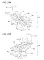
- the inner side edge of the play-fit hole 63a formed in the movable contact piece 60 is locked to the lock receiving portion 53a formed at the projection piece 53 of the common terminal 50, one end 73a of the plate spring 73 is locked to the lock receiving portion 53b formed at the projection piece 53, and the other end 73b of the plate spring 73 is locked to the inner side edge of the play-fit hole 63c (see Figs. 20A, 20B ).
- the common terminal 50 is then press fit and positioned in the slit 14c of the base 14 shown in Fig.
- the operating element 20 is fitted into the operation hole 14a of the base 14, and then the positioning bosses 15a, 15b of the cover 15 are inserted to the attachment holes 14f, 14g of the base 14 shown in Fig. 19 .
- the rivet 15d is then inserted and caulked in the rivet holes 14h, 15c, whereby the assembly task is completed.
- the movable contact piece 60 bends when the operating element 20 is pushed down.
- the reference line (not shown) connecting the lock receiving portion 53a of the projection piece 53 and the other end 73b of the plate spring 73 goes over the lock receiving portion 53b of the projection piece 53, the movable contact piece 60 inverts with the lock receiving portion 53a as the supporting point by the spring force of the plate spring 73 ( Figs. 23A to 23C ).
- the movable contact 63a switches from the always-closed fixed contact 45a to the always-opened fixed contact 40a, and when the operating element 20 is further pushed in, the movable contact 63a is brought into contact with the always-opened fixed contact 40a at a predetermined contact pressure ( Figs. 24A to 24C ).
- the movable contact piece 60 When the load of the operating element 20 is released, the movable contact piece 60 is inverted by the spring force of the plate spring 73, and the movable contact 63a is switched from the always-opened fixed contact 40a to the always-closed fixed contact 45a to return to the original state.
- the plate spring 73 elastically deforms and vibrates when the movable contact piece 60 is turned, but the plate spring 73 is brought into contact with the projection 14i arranged on the base 14 thus shifting the timing of increasing the amplitude and preventing the resonance phenomenon. Similarly, the resonance phenomenon can be prevented even if an impact force is applied from the outside since the plate spring 73 is brought into contact with the projection 14i of the cover 15.
- a switch according to a fourth embodiment has the contact mechanism 30 assembled in the housing 10 formed by a base 16 and a cover 17, by which contact mechanism 30 can be operated with the operating element 20 assembled to the housing 10.
- the base 16 includes an operation hole 16a for assembling the operating element 20 at the upper surface, and a recess 16b for assembling an operation lever (not shown).
- the base 16 includes slits 16c, 16d, 16e to which the common terminal 50, the always-opened fixed contact terminal 40, and the always-closed fixed contact terminal 45 can be press fit from the side.
- base 16 has attachment holes 16f, 16g formed at the opposing corners.
- a projection 16h is arranged between the operation hole 16a and the attachment hole 16g ( Fig. 27 ).
- the cover 17 has a side surface shape capable of being fitted into the base 16, and includes press-fit bosses 17a, 17b at positions corresponding to the attachment holes 16f, 16g.
- the contact mechanism 30 incudes the common terminal 50 for assembling the movable contact piece 60, the plate spring 74, and the operation piece 84, and the always-opened fixed contact terminal 40 and the always-closed fixed contact terminal 45 having the always-opened fixed contact 40a and the always-closed fixed contact 45a arranged at one end.
- the common terminal 50 is formed to a step-form through press working, and includes lock receiving portions 54a, 54b inducing through-holes at the corners.
- the movable contact piece 60 includes a movable contact 64a at one end by punching out a conductive plate spring and is formed with reinforcement ribs 64b, 65b by bending and raising both side edges.
- a pair of lock nails 64c, 64c is bent and raised at the opening edge in the vicinity of the movable contact 64a of the opening edge of the movable contact piece 60.
- the plate spring 74 is formed by curving a band-shaped spring material through press working, where one end 74a and the other end 74b have a lockable shape.
- the operation piece 84 is bent to a substantially L-shape, where a lock portion 84a is formed at the distal end of the horizontal portion, an operation receiving portion 84b is formed at the upper end of the vertical portion, and a lock receiving portion 84c is formed at the outward surface.
- the lock portion 84a of the operation piece 84 is locked to the lock receiving portion 54a arranged at the corner of the common terminal 50 from the lower side, and the inner side edge of the movable contact piece 60 is locked to the lock receiving portion 84c of the operation piece 84. Furthermore, one end 74a of the plate spring 74 is locked to the lock nail portions 64c, 64c of the movable contact piece 60 and one end 74b of the plate spring 74 is locked to the lock receiving portion 54b arranged at the corner of the common terminal 50 (see Figs. 28A and 28B ). The common terminal 50 is then press fit to the slit 16c of the base 16 shown in Fig.
- the always-opened fixed contact terminal 40 and the always-closed fixed contact terminal 45 are respectively press fit to the slits 16d, 16e for positioning.
- the movable contact 64a is thus positioned between the always-opened fixed contact 40a and the always-closed fixed contact 45a, and is biased to the upper side.
- the operating element 20 is then fitted into and positioned in the operation hole 16a of the base 16, and thereafter, the positioning bosses 17a, 17b of the cover 17 are press fit and integrated to the operation holes 16f, 16g of the base 16 to complete the assembly task.
- the movable contact 64a switches from the always-closed fixed contact 45a to the always-opened fixed contact 40a.
- the movable contact 64a is brought into contact with the always-opened fixed contact 40a at a predetermined contact pressure ( Figs. 32A fo 32C).
- the plate spring 74 elastically deforms and vibrates when the movable contact piece 60 turns, but the projection 16h arranged on the base 16 is brought into contact with the plate spring 74 thus shifting the timing of increasing the amplitude and preventing the resonance phenomenon. Similarly, the resonance phenomenon can be prevented even if an impact force is applied from the outside since the plate spring 74 is brought into contact with the projection 16h.
- the resonance experiment was conducted using samples of the switches according to the first and second embodiments as an example.
- the resonance experiment was similarly conducted under the same condition using a sample of a switch in which the tongue piece is not arranged as a comparative example.
- the measurement results are shown in the graph of Fig. 33 .
- the resonance phenomenon did not occur in the coil spring in the example in which the tongue piece is arranged.
- the coil spring greatly vibrates and resonates in the comparative example in which the tongue piece is not arranged.
- the movable contact piece and the movable contact also vibrate with the resonance phenomenon of the coil spring. According to the above experimental results, the false operation can be prevented and the lifespan can be extended by having the tongue piece inhibit the occurrence of the resonance phenomenon.
- the switch according to the present invention is not limited to the above, and application may, obviously, be made on other micro-switches.
Landscapes
- Push-Button Switches (AREA)
Abstract
Description
- The present invention relates to switches, and in particular, to a micro-switch capable of inhibiting the occurrence of resonance phenomenon and preventing false operation.
- Conventionally, the switch may be a brake lever interlocking switch including a switch case, a swing plate attached to the switch case to swing interlocking with the brake lever, a plurality of push rods that is attached to the switch case to push down with the swing plate and that has different distances from the center of rotation of the swing plate, and a switch means facing such push rods (see Japanese Unexamined Patent Publication No.
10-297364 - In the above-described switch, however, the amplitude of a spring 99 or a spring member increases by the vibration generated when opening and closing the contact or the impact force applied from the outside, and the resonance phenomenon tends to easily occur, as shown in
Fig. 8 thereof. When the resonance phenomenon occurs, not only does false operation occur, but the spring member easily breaks, the contact wears, and the contact lifespan becomes short.
The present invention has been devised to solve the problems described above, and an object thereof is to provide a switch capable of inhibiting the occurrence of the resonance phenomenon caused by the increase of the amplitude of the spring member and preventing false operation, and furthermore, preventing the breakage of the spring member and realizing long contact lifespan. - In accordance with one aspect of the present invention, there is provided a switch in which a movable contact piece of a contact mechanism arranged in a housing is operated with an operating element, and the movable contact piece is operated with a spring member of the contact mechanism to open and close a contact; wherein a regulating means for suppressing vibration of the spring member is arranged at a position of contacting the spring member. Especially, the regulating means may be arranged to be brought into contact with the spring member at time of resonance.
- According to the present invention, when the contact mechanism is operated with the operating element or when the impact force is applied from the outside, the spring member is not brought into contact with the regulating means if the spring member is not vibrating, whereas the spring member is brought into contact with the regulating means if the spring member is vibrating, particularly, if the spring member starts to vibrate. As a result, the regulating means shifts the timing to increase the amplitude of the spring member so that the amplitude of the spring member does not increase and the resonance phenomenon can be inhibited. Therefore, the false operation can be prevented, and furthermore, the breakage of the spring member can be prevented and the wear of the contact can be reduced so that a switch of longer contact lifespan can be realized.
- In the above aspect, the spring member may be a coil member.
According to such aspect, a switch having a large degree of freedom of design can be realized since the elastic displacement amount of the coil spring is large. - In the above aspect, the spring member may be a plate spring integral with the movable contact piece.
According to such aspect, a switch with less number of components and number of assembly steps and with high productivity can be obtained. - In the above aspect, the spring member may be a plate spring of a separate body from the movable contact piece.
According to such aspect, a switch having a large degree of freedom of design can be realized by using the plate spring of a separate body. - In the above aspect, the regulating means may be a tongue piece cutout from a terminal of the contact mechanism.
According to such aspect, a switch with less number of components and number of assembly steps and with high productivity can be obtained. - In a new aspect of the present invention, the regulating means may be a projection arranged in a projecting manner on the inner surface of the housing or a bulging portion bulging out from the inner surface of the housing.
According to the present aspect, a switch with high productivity can be obtained by integrally molding the regulating means at the same time as the housing.
The projection or the bulging portion may be assembled after being molded separate from the housing rather than being integrally molded on the inner surface of the housing. -
Figs. 1A, 1B, and 1C are perspective views showing a first embodiments of a switch according to the present invention; -
Fig. 2 is an exploded perspective view of the switch shown inFig. 1B ; -
Fig. 3 is an exploded perspective view of the switch shown inFig. 1C ; -
Figs. 4A and 4B are perspective views showing a contact mechanism of the switch shown inFigs. 1A to 1C ; -
Figs. 5A, 5B, and 5C are a front view describing the operation process, a cross-sectional view cut at a position of removing only the side wall on the front surface side of the housing, and a cross-sectional view cut at a position of vertically dividing the operating element in half; -
Figs. 6A, 6B, and 6C are a front view describing the operation process, a cross-sectional view cut at a position of removing only the side wall on the front surface side of the housing, and a cross-sectional view cut at a position of vertically dividing the operating element in half; -
Figs. 7A, 7B, and 7C are a front view describing the operation process, a cross-sectional view cut at a position of removing only the side wall on the front surface side of the housing, and a cross-sectional view cut at a position of vertically dividing the operating element in half; -
Figs. 8A, 8B, and 8C are a front view describing the operation process, a cross-sectional view cut at a position of removing only the side wall on the front surface side of the housing, and a cross-sectional view cut at a position of vertically dividing the operating element in half; -
Figs. 9A and 9B are perspective views showing a second embodiment of a switch according to the present invention; -
Fig. 10 is an exploded perspective view of the switch shown inFig. 9A ; -
Fig. 11 is an exploded perspective view of the switch shown inFig. 9B ; -
Figs. 12A and 12B are perspective views showing a contact mechanism integrally molded with the base shown inFigs. 1A to 1C ; -
Figs. 13A, 13B, and 13C are a front view describing the operation process, a cross-sectional view cut at a position of removing only the side wall on the front surface side of the housing, and a cross-sectional view cut at a position of vertically dividing the operating element in half; -
Figs. 14A, 14B, and 14C are a front view describing the operation process, a cross-sectional view cut at a position of removing only the side wall on the front surface side of the housing, and a cross-sectional view cut at a position of vertically dividing the operating element in half; -
Figs. 15A, 15B, and 15C are a front view describing the operation process, a cross-sectional view cut at a position of removing only the side wall on the front surface side of the housing, and a cross-sectional view cut at a position of vertically dividing the operating element in half; -
Figs. 16A, 16B, and 16C are a front view describing the operation process, a cross-sectional view cut at a position of removing only the side wall on the front surface side of the housing, and a cross-sectional view cut at a position of vertically dividing the operating element in half; -
Figs. 17A and 17B are perspective views showing a third embodiment of a switch according to the present invention; -
Fig. 18 is an exploded perspective view of the switch shown inFig. 17A ; -
Fig. 19 is an exploded perspective view in which the switch shown inFig. 17B is viewed from the lower side; -
Figs. 20A and 20B are perspective views showing a contact mechanism of the switch shown inFigs. 17A and 17B ; -
Figs. 21A, 21B, and 21C are a front view describing the operation process, a cross-sectional view cut at a position of removing only the side wall on the front surface side of the housing, and a cross-sectional view cut at a position of vertically dividing the operating element in half; -
Figs. 22A, 22B, and 22C are a front view describing the operation process, a cross-sectional view cut at a position of removing only the side wall on the front surface side of the housing, and a cross-sectional view cut at a position of vertically dividing the operating element in half; -
Figs. 23A, 23B, and 23C are a front view describing the operation process, a cross-sectional view cut at a position of removing only the side wall on the front surface side of the housing, and a cross-sectional view cut at a position of vertically dividing the operating element in half; -
Figs. 24A, 24B, and 24C are a front view describing the operation process, a cross-sectional view cut at a position of removing only the side wall on the front surface side of the housing, and a cross-sectional view cut at a position of vertically dividing the operating element in half; -
Figs. 25A, 25B, and 25C are perspective views showing a fourth embodiment of a switch according to the present invention; -
Fig. 26 is an exploded perspective view in which the switch shown inFig. 25A is viewed from the lower side; -
Fig. 27 is an exploded perspective view of the switch shown inFig. 25C ; -
Figs. 28A and 28B are perspective views showing a contact mechanism of the switch shown inFigs. 25A, 25B, and 25C ; -
Figs. 29A, 29B, and 29C are a front view describing the operation process, a cross-sectional view cut at a position of removing only the side wall on the front surface side of the housing, and a cross-sectional view cut at a position of vertically dividing the operating element in half; -
Figs. 30A, 30B, and 30C are a front view describing the operation process, a cross-sectional view cut at a position of removing only the side wall on the front surface side of the housing, and a cross-sectional view cut at a position of vertically dividing the operating element in half; -
Figs. 31A, 31B, and 31C are a front view describing the operation process, a cross-sectional view cut at a position of removing only the side wall on the front surface side of the housing, and a cross-sectional view cut at a position of vertically dividing the operating element in half; -
Figs. 32A, 32B, and 32C are a front view describing the operation process, a cross-sectional view cut at a position of removing only the side wall on the front surface side of the housing, and a cross-sectional view cut at a position of vertically dividing the operating element in half; and -
Fig. 33 is a graph showing the measurement result of the vibration experiment conducted on the first embodiment. - Hereinafter, preferred embodiments of the present invention will be described with reference to the accompanied drawings
Figs. 1A to 1C toFigs. 32A to 32C .
As shown in the accompanied drawingsFigs. 1A to 1C toFigs. 8A to 8C , a switch according to a first embodiment is configured by ahousing 10, an operatingelement 20 attached to thehousing 10 through arubber cap 25, and acontact mechanism 30 assembled to aholder 31 incorporated in thehousing 10 from the side and operated by the operatingelement 20. - As shown in
Fig. 1A , thehousing 10 includes anattachment hole 11b at a side surface of astep portion 11 a arranged on one side of a one side surface of a housing main body 11, and has apositioning boss 11c arranged in a projecting manner on the other side. As shown inFig. 1B , the housing main body 11 includes a vertically long assembly opening 11d at the end face on the other side. Furthermore, the housing main body 11 has anoperation hole 11f arranged between a pair ofprotection barriers Fig. 2 ). - As shown in
Fig. 2 , the operatingelement 20 is assembled to theoperation hole 11f of thehousing 10 so as to be movable up and down by fitting an annular edge of anopening 26 of therubber cap 25 to an annular groove 21 a formed on the upper side. A slip-out preventingprojection 21 b is projected to the side at the outer peripheral surface on the lower side of the operating element 20 (Fig. 3 ). - As shown in
Fig. 2 , thecontact mechanism 30 has acommon terminal 50 arranged between an always-openedfixed contact terminal 40 and an always-closedfixed contact terminal 45 assembled to theholder 31. An always-openedfixed contact 40a and an always-closedfixed contact 45a are respectively arranged at one end of the always-openedfixed contact terminal 40 and the always-closedfixed contact terminal 45. Amovable contact piece 60, acoil spring 70 serving as a spring member, and anoperation piece 80 are assembled to thecommon terminal 50. - The
holder 31 has an outer peripheral shape that can be inserted from anassembly opening 11d of thehousing 10, and has press-fit slits vertical wall 32. A pair ofguide projections vertical wall 32 to position regulate theoperating element 20, to be described later. - The
common terminal 50 has a pair of raisedpieces piece 51 has acutout 51 a formed at the upper end and has alock receiving portion 51 b formed at the outward edge of the raisedpiece 51. Thecommon terminal 50 has atongue piece 51 c cut and raised between the raisedpieces 51. Furthermore, thecommon terminal 50 incudes alock hole 51d in the vicinity of thetongue piece 51c.
Thetongue piece 51 c prevents resonance of thecoil spring 70 by bringing a bent portion formed by bending the distal end edge to the lower side into contact with the lower surface of thecoil spring 70 to be described later. The bent portion may have a shape that not only point contacts thecoil spring 70, but also line contacts or area contacts thereto. In particular, if configured to line contact or area contact, thecoil spring 70 can be reliably brought into contact with the bent portion even if the dimensional accuracy and the assembly accuracy of the components vary, so that the amplification of the amplitude of thecoil spring 70 can be more reliably prevented. - The
movable contact piece 60 is a conductive plate spring having a substantially U-shape, where amovable contact 61 a is arranged at one end and alock portion 61b that becomes a supporting point of turn is formed at both ends on the other end side. Themovable contact piece 60 also includes a lock hole 61 c in the vicinity of themovable contact 61 a. - The
coil spring 70 has oneend 71 a lockable to the lock hole 61 c of themovable contact piece 60 and theother end 71 b lockable to thelock hole 51 d of thecommon terminal 50. - The
operation piece 80 has anengagement shaft portion 81 a formed along the edge on one side, and a slip-out preventingprojection 81 b that engages thecutout 51a of the raisedpiece 51 arranged to project to the side at both side edges of the intermediate portion. Theoperation piece 80 has alock receiving portion 81d arranged at a distal end of anarm portion 81c bent down from both side edges on the other side, and has the other end serving as anoperation receiving portion 81e. - The assembly method of the switch according to the first embodiment will now be described.
First, the oneend 71 a of thecoil spring 70 shown inFig. 2 is locked to the lock hole 61 c of themovable contact piece 60, and theother end 71 b is locked to thelock hole 51 d of thecommon terminal 50. As shown inFig. 4A and Fig. 4B , the slip-out preventingprojection 81 b of theoperation piece 80 is engaged to thecutout 51 a of thecommon terminal 50, and thereafter theengagement shaft portion 81 a of theoperation piece 80 is engaged to thelock receiving portion 51 b of thecommon terminal 50 and thelock portion 61 b of themovable contact piece 60 is locked to lock receivingportion 81 d formed in thearm portion 81c. Themovable contact piece 60 is thereby biased towards the lower side by the spring force of thecoil spring 70. - Furthermore, the
common terminal 50 shown inFig. 2 is press fit and positioned in the slit 32a of theholder 31, and the always-closedfixed contact terminal 45, the always-openedfixed contact terminal 40 are press fit to theslits movable contact 61 a faces the always-closedfixed contact 45a and the always-openedfixed contact 40a so as to approach or separate thereto. - After inserting the
holder 31 from theopening 11 d of thehousing 10, it is shielded with a resin mold. The opening edge on the lower side of therubber cap 25 is fitted and thermally caulked to the opening edge of theoperation hole 11f of thehousing 10, and then the operatingelement 20 is press fit from theopening 26 of therubber cap 25 and the opening edge of therubber cap 25 is elastically fitted and sealed to the annular groove 21 a of the operatingelement 20. - The operation method of the switch will now be described. First, as shown in
Figs. 5A to 5C , theoperation receiving portion 81e of theoperation piece 80 is biased to the upper side by the spring force of thecoil spring 70 and the operatingelement 20 is also biased to the upper side in the no-load state. However, the operatingelement 20 does not slip out since the slip-out preventingprojection 21b is locked to the top surface of thehousing 10. Themovable contact 61a is brought into contact with the always-closedfixed contact 45a and separated from the always-openedfixed contact 40a. - As shown in
Figs. 6A to 6C , when theoperation receiving portion 81e of theoperation piece 80 is pushed down with the operatingelement 20, theengagement shaft portion 81 a of theoperation piece 80 turns with thelock receiving portion 51 b of the raisedpiece 51 as the supporting point. When thelock receiving portion 81d of theoperation piece 80 goes over the reference line (not shown) connecting both ends 71 a, 71 b of thecoil spring 70, themovable contact piece 60 is inverted and themovable contact 61 a is switched from the always-closedfixed contact 45a to the always-openedfixed contact 40a (Figs. 7A to 7C ). Furthermore, when the operatingelement 20 is pushed down, themovable contact 61 a is brought into contact with the always-openedfixed contact 40 at a predetermined contact pressure (Figs. 8A to 8C ). - When the pushing force with respect to the
operating element 20 is released, themovable contact piece 60 is turned in the reverse direction with the spring force of thecoil spring 70, and the operatingelement 20 is pushed to the upper side. Thus, themovable contact 61 a is switched from the always-openedfixed contact 40a to the always-closedfixed contact 45a to return to the original position. The operatingelement 20 does not move out from thehousing 10 since the slip-out preventingprojection 21 b locks to the top surface of thehousing 10. - In the course of operation, the vibration occurs by the extension and contraction of the
coil spring 70 when themovable contact piece 60 is turned, where thetongue piece 51 c arranged on thecommon terminal 50 is brought into contact with thecoil spring 70 thus shifting the timing of increasing the amplitude and preventing the resonance phenomenon.
Similarly, the resonance phenomenon caused by the increase of the amplitude can be prevented even if an impact force is applied from the outside since thecoil spring 70 is brought into contact with thetongue piece 51 c. - As shown in
Figs. 9A and 9B toFigs. 16A to 16C , the switch according to the second embodiment is configured by thehousing 10, the operatingelement 20 attached to thehousing 10, and thecontact mechanism 30 incorporated in thehousing 10 and operated by the operatingelement 20. - As shown in
Fig. 10 , thehousing 10 is configured by a base 12 in which the always-openedfixed contact terminal 40, the always-closedfixed contact terminal 45, and thecommon terminal 50 are insert molded, and acover 13 having a planar shape that can be fitted to thebase 12. Thecontact mechanism 30 is configured by the always-openedfixed contact terminal 40, the always-closedfixed contact terminal 45, thecommon terminal 50, and themovable contact piece 60, to be described later. - The
base 12 has the always-openedfixed contact terminal 40 and the always-closedfixed contact terminal 45 projected from the upper surface, where the always-openedfixed contact 40a and the always-closedfixed contact 45a are respectively arranged at the upper end, the always-openedfixed contact 40a and the always-closedfixed contact 45a being faced to each other. The base has a pair ofprojection pieces common terminal 50 projecting out at the upper surface, wherelock receiving portions projection pieces base 12 has an engagement nail portion12a formed on both side surfaces facing each other. - The
cover 13 has a recessedarea 13b for attaching the operation lever (not shown) formed in the vicinity of theoperation hole 13a formed at the upper surface. Thecover 13 has anengagement hole 13c formed at the corner on the lower side of the opposing side surface. Moreover, as shown inFig. 11 , thecover 13 has aprojection 13d for position regulating aplate spring 72, to be described later, arranged in a projecting manner at the top surface. - As shown in
Fig. 10 , themovable contact piece 60 configuring thecontact mechanism 30 is formed by performing press work on a conductive plate spring material, where amovable contact 62a is arranged on the end on the near side, and a fit-inhole 62b is formed on the far side. Furthermore, anarcuate plate spring 72 performed with bending work is cut out between themovable contact 62a and the fit-inhole 62b. A lock portion 72a is arranged at the free end of theplate spring 72. - The operating
element 20 has a planar shape that can be fitted to theoperation hole 13a of thecover 13, and has a pair of slip-out preventing projections 22a, 22a arranged in a projecting manner to the side at the lower end. - The assembly method according to the present embodiment will now be described.
First, as shown inFig. 10 , an inner side edge of the fit-inhole 62b of themovable contact piece 60 is locked to thelock receiving portion 52a of theprojection piece 52 on one side projecting out from thebase 12, and the lock portion 72a of theplate spring 72 is locked to thelock receiving portion 52b of theprojection piece 52 on the other side. Themovable contact 62a is thus positioned between the always-openedfixed contact 40a and the always-closedfixed contact 45a, and is biased to the upper side (figs. 12A, 12B ). - The
cover 13 in which theoperating element 20 is assembled to theoperation hole 13a is fitted into thebase 12, and theengagement nail portion 12a of thebase 12 is engaged and integrated with theengagement hole 13c of thecover 13. The lower end of the operatingelement 20 shown inFig. 11 is thereby brought into contact with themovable contact piece 60, and theprojection 13d can be brought into contact with theplate spring 72 of themovable contact piece 60. - The operation method of the switch according to the present embodiment will now be described.
As shown inFigs. 13A to 13C , themovable contact 62a is brought into contact with the always-closedfixed contact 45 at a predetermined contact pressure by the spring force of theplate spring 72 of themovable contact piece 60 when the operatingelement 20 is in the no-load state. - As shown in
Figs. 14A to 14C andFigs. 15A to 15C , themovable contact piece 60 bends when the operatingelement 20 is pushed down. When the lower end of the operatingelement 20 goes over the reference line (not shown) connecting thelock receiving portions projection pieces movable contact piece 60 is inverted with thelock receiving portion 52a as a supporting point by the spring force of the plate spring 72 (Figs. 16A to 16C ). Themovable contact 62a is thereby switched from the always-closedfixed contact 45a to the always-openedfixed contact 40a, and themovable contact 62a is brought into contact with the always-openedfixed contact 40 at a predetermined contact pressure by further pushing in theoperating element 20. - When the load of the operating
element 20 is released, themovable contact piece 60 is inverted by the spring force of theplate spring 72, and themovable contact 62a is switched from the always-openedfixed contact 40a to the always-closedfixed contact 45a to return to the original state. - The
plate spring 72 elastically deforms and vibrates when themovable contact piece 60 is turned, but theposition regulating projection 13d of thecover 13 is brought into contact with theplate spring 72 thus shifting the timing of increasing the amplitude and preventing the resonance phenomenon.
Similarly, the resonance phenomenon caused by the increase of the amplitude can be prevented even if an impact force is applied from the outside since theplate spring 72 is brought into contact with theprojection 13d of thecover 13. In particular, the slip-out of themovable contact piece 60 can be prevented even if horizontal oscillation is applied since the distal end of theprojection 13d is fitted to themovable contact piece 60. - As shown in
Figs. 17A and 17B toFigs. 24A to 24C , a switch according to a third embodiment has thecontact mechanism 30 incorporated in thehousing 10 formed by thebase 14 and thecover 15, and has thecontact mechanism 30 operable with the operatingelement 20 assembled to thehousing 10. - As shown in
Fig. 18 , thebase 14 includes an operation hole 14a for assembling the operatingelement 20, and includes anattachment hole 14b for assembling an operation lever (not shown) in the vicinity of the operation hole 14a. Thebase 10 includes slits 14c, 14d, 14e to which thecommon terminal 50, the always-closedfixed contact terminal 45, and the always-openedfixed contact terminal 40 can be press fit from the side. Thebase 10 includes a pair of attachment holes 14f, 14g, and a rivet hole 14e is formed between the attachment holes 14f, 14g. Thebase 10 has aprojection 14i arranged in a projecting manner at the top surface. - As shown in
Fig. 19 , thecover 15 has a side surface shape that can be fitted to thebase 14, where fit-inbosses rivet hole 15c is also formed. - As shown in
fig. 18 , thecontact mechanism 30 includes the always-openedfixed contact terminal 40 and the always-closedfixed contact terminal 45 respectively including the always-openedfixed contact 40a and the always-closedfixed contact 45a at the upper end, and thecommon terminal 50 for assembling themovable contact piece 60 and acurved plate spring 73. - The
common terminal 50 is formed withlock receiving portions projection pieces - The
movable contact piece 60 includes amovable contact 63a at one end and is formed with a pair of play-fit holes - The
plate spring 73 is formed by curving a band-shaped spring material through press working, where one end 73a and theother end 73b can be locked. - The assembly method according to the present embodiment will now be described.
First, as shown inFig. 18 , the inner side edge of the play-fit hole 63a formed in themovable contact piece 60 is locked to thelock receiving portion 53a formed at theprojection piece 53 of thecommon terminal 50, one end 73a of theplate spring 73 is locked to thelock receiving portion 53b formed at theprojection piece 53, and theother end 73b of theplate spring 73 is locked to the inner side edge of the play-fit hole 63c (seeFigs. 20A, 20B ). Thecommon terminal 50 is then press fit and positioned in the slit 14c of the base 14 shown inFig. 18 , and the always-closedfixed contact terminal 45 and the always-openedfixed contact terminal 40 are respectively press fit and positioned in the slits 14d, 14e. Themovable contact 63a is thus positioned between the always-closedfixed contact 45a and the always-openedfixed contact 40a, and is biased to the upper side. Thereafter, the operatingelement 20 is fitted into the operation hole 14a of thebase 14, and then thepositioning bosses cover 15 are inserted to the attachment holes 14f, 14g of the base 14 shown inFig. 19 . Therivet 15d is then inserted and caulked in therivet holes - The operation method of the switch according to the present embodiment will now be described.
As shown inFigs. 21A to 21C , if the operatingelement 20 is in the no-load state, themovable contact 63a is brought into contact with the always-closedfixed contact 45a at a predetermined contact pressure by the spring force of theplate spring 73 assembled to themovable contact piece 60, - As shown in
Figs. 22A to 22C , themovable contact piece 60 bends when the operatingelement 20 is pushed down. When the reference line (not shown) connecting thelock receiving portion 53a of theprojection piece 53 and theother end 73b of theplate spring 73 goes over thelock receiving portion 53b of theprojection piece 53, themovable contact piece 60 inverts with thelock receiving portion 53a as the supporting point by the spring force of the plate spring 73 (Figs. 23A to 23C ). Therefore, themovable contact 63a switches from the always-closedfixed contact 45a to the always-openedfixed contact 40a, and when the operatingelement 20 is further pushed in, themovable contact 63a is brought into contact with the always-openedfixed contact 40a at a predetermined contact pressure (Figs. 24A to 24C ). - When the load of the operating
element 20 is released, themovable contact piece 60 is inverted by the spring force of theplate spring 73, and themovable contact 63a is switched from the always-openedfixed contact 40a to the always-closedfixed contact 45a to return to the original state. - The
plate spring 73 elastically deforms and vibrates when themovable contact piece 60 is turned, but theplate spring 73 is brought into contact with theprojection 14i arranged on the base 14 thus shifting the timing of increasing the amplitude and preventing the resonance phenomenon.
Similarly, the resonance phenomenon can be prevented even if an impact force is applied from the outside since theplate spring 73 is brought into contact with theprojection 14i of thecover 15. - As shown in
Figs. 25A to 25C toFigs. 32A to 32C , a switch according to a fourth embodiment has thecontact mechanism 30 assembled in thehousing 10 formed by abase 16 and acover 17, by whichcontact mechanism 30 can be operated with the operatingelement 20 assembled to thehousing 10. - As shown in
Figs. 25A to 25C , thebase 16 includes anoperation hole 16a for assembling the operatingelement 20 at the upper surface, and arecess 16b for assembling an operation lever (not shown). As shown inFig. 26 , thebase 16 includesslits common terminal 50, the always-openedfixed contact terminal 40, and the always-closedfixed contact terminal 45 can be press fit from the side. Furthermore,base 16 hasattachment holes 16f, 16g formed at the opposing corners. Aprojection 16h is arranged between theoperation hole 16a and theattachment hole 16g (Fig. 27 ). - The
cover 17 has a side surface shape capable of being fitted into thebase 16, and includes press-fit bosses attachment holes 16f, 16g. - As shown in
Fig. 26 , thecontact mechanism 30 incudes thecommon terminal 50 for assembling themovable contact piece 60, theplate spring 74, and theoperation piece 84, and the always-openedfixed contact terminal 40 and the always-closedfixed contact terminal 45 having the always-openedfixed contact 40a and the always-closedfixed contact 45a arranged at one end. - The
common terminal 50 is formed to a step-form through press working, and includeslock receiving portions - The
movable contact piece 60 includes amovable contact 64a at one end by punching out a conductive plate spring and is formed withreinforcement ribs 64b, 65b by bending and raising both side edges. A pair oflock nails movable contact 64a of the opening edge of themovable contact piece 60. - The
plate spring 74 is formed by curving a band-shaped spring material through press working, where one end 74a and theother end 74b have a lockable shape. - As shown in
Fig. 27 , theoperation piece 84 is bent to a substantially L-shape, where alock portion 84a is formed at the distal end of the horizontal portion, anoperation receiving portion 84b is formed at the upper end of the vertical portion, and alock receiving portion 84c is formed at the outward surface. - The assembly method according to the present embodiment will now be described.
First, as shown inFig. 26 , thelock portion 84a of theoperation piece 84 is locked to thelock receiving portion 54a arranged at the corner of thecommon terminal 50 from the lower side, and the inner side edge of themovable contact piece 60 is locked to thelock receiving portion 84c of theoperation piece 84. Furthermore, one end 74a of theplate spring 74 is locked to thelock nail portions movable contact piece 60 and oneend 74b of theplate spring 74 is locked to thelock receiving portion 54b arranged at the corner of the common terminal 50 (seeFigs. 28A and 28B ). Thecommon terminal 50 is then press fit to theslit 16c of the base 16 shown inFig. 26 for positioning, and the always-openedfixed contact terminal 40 and the always-closedfixed contact terminal 45 are respectively press fit to theslits movable contact 64a is thus positioned between the always-openedfixed contact 40a and the always-closedfixed contact 45a, and is biased to the upper side. The operatingelement 20 is then fitted into and positioned in theoperation hole 16a of thebase 16, and thereafter, thepositioning bosses cover 17 are press fit and integrated to theoperation holes 16f, 16g of the base 16 to complete the assembly task. - The operation method of the switch according to the present embodiment will now be described.
As shown inFigs. 29A to 29C , if the operatingelement 20 is in the no-load state, themovable contact 64a is brought into contact with the always-closedfixed contact 45a at a predetermined contact pressure by the spring force of theplate spring 74 assembled to themovable contact piece 60. - As shown in
Figs. 30A to 30C , when the operatingelement 20 is pushed down to push down theoperation receiving portion 84b of theoperation piece 84, theoperation piece 84 turns with thelock portion 84a as the supporting point and themovable contact piece 60 lowers. When the reference line (not shown) connecting thelock receiving portion 84c of theoperation piece 84 and the one end 74a of theplate spring 74 goes over theother end 74b of theplate spring 74, themovable contact piece 60 inverts with thelock receiving portion 84c of theoperation piece 84 as the supporting point by the spring force of the plate spring 74 (Figs. 31A to 31C ). Therefore, themovable contact 64a switches from the always-closedfixed contact 45a to the always-openedfixed contact 40a. When the operatingelement 20 is further pushed in, themovable contact 64a is brought into contact with the always-openedfixed contact 40a at a predetermined contact pressure (Figs. 32A fo 32C). - When the load of the operating
element 20 is released, themovable contact piece 60 is inverted by the spring force of theplate spring 74, and themovable contact 64a is switched from the always-openedfixed contact 40a to the always-closedfixed contact 45a to return to the original state. - The
plate spring 74 elastically deforms and vibrates when themovable contact piece 60 turns, but theprojection 16h arranged on thebase 16 is brought into contact with theplate spring 74 thus shifting the timing of increasing the amplitude and preventing the resonance phenomenon.
Similarly, the resonance phenomenon can be prevented even if an impact force is applied from the outside since theplate spring 74 is brought into contact with theprojection 16h. - The resonance experiment was conducted using samples of the switches according to the first and second embodiments as an example. The resonance experiment was similarly conducted under the same condition using a sample of a switch in which the tongue piece is not arranged as a comparative example. The measurement results are shown in the graph of
Fig. 33 . - As shown in
Fig. 33A , the resonance phenomenon did not occur in the coil spring in the example in which the tongue piece is arranged.
As apparent fromFig. 33B , the coil spring greatly vibrates and resonates in the comparative example in which the tongue piece is not arranged. Thus, it tends to easily break with increase in the number of stress oscillations and the lifespan also becomes shorter even if the stress amplitude width is within the elastic region. It is also recognized that the movable contact piece and the movable contact also vibrate with the resonance phenomenon of the coil spring.
According to the above experimental results, the false operation can be prevented and the lifespan can be extended by having the tongue piece inhibit the occurrence of the resonance phenomenon. - The switch according to the present invention is not limited to the above, and application may, obviously, be made on other micro-switches.
Claims (8)
- A switch in which a movable contact piece of a contact mechanism (30) arranged in a housing (10) is operated with an operating element (20), and the movable contact piece is operated with a spring member (70) of the contact mechanism (30) to open and close a contact; characterized in that
a regulating means (51 c) for suppressing vibration of the spring member (70) is arranged at a position of contacting the spring member (70). - The switch according to claim 1, characterized in that the regulating means (51c) is arranged to be brought into contact with the spring member (70) at time of resonance.
- The switch according to claim 1 or 2, characterized in that the spring member (70) is a coil member.
- The switch according to claim 1 or 2, characterized in that the spring member (70) is a plate spring integral with the movable contact piece.
- The switch according to claim 1 or 2, characterized in that the spring member (70) is a plate spring of a separate body from the movable contact piece.
- The switch according to any one of claim 1 to 5, characterized in that the regulating means (51 c) is a tongue piece cutout from a terminal of the contact mechanism (30).
- The switch according to any one of claims 1 to 5, characterized in that the regulating means (51 c) is a projection arranged in a projecting manner on an inner surface of the housing (10).
- The switch according to any one of claims 1 to 5, characterized in that the regulating means (51 c) is a bulging portion bulging out from an inner surface of the housing (10).
Applications Claiming Priority (2)
| Application Number | Priority Date | Filing Date | Title |
|---|---|---|---|
| JP2010153033 | 2010-07-05 | ||
| JP2011024625A JP5691584B2 (en) | 2010-07-05 | 2011-02-08 | switch |
Publications (2)
| Publication Number | Publication Date |
|---|---|
| EP2405455A1 true EP2405455A1 (en) | 2012-01-11 |
| EP2405455B1 EP2405455B1 (en) | 2013-10-16 |
Family
ID=44741762
Family Applications (1)
| Application Number | Title | Priority Date | Filing Date |
|---|---|---|---|
| EP11169774.4A Not-in-force EP2405455B1 (en) | 2010-07-05 | 2011-06-14 | Switch |
Country Status (4)
| Country | Link |
|---|---|
| US (1) | US8658928B2 (en) |
| EP (1) | EP2405455B1 (en) |
| JP (1) | JP5691584B2 (en) |
| CN (1) | CN102315028B (en) |
Families Citing this family (4)
| Publication number | Priority date | Publication date | Assignee | Title |
|---|---|---|---|---|
| CN105408165B (en) * | 2013-06-14 | 2018-03-30 | 海基哈格应用有限公司 | Method and system for the regenerating braking energy using rail vehicle |
| TWI503855B (en) * | 2013-07-05 | 2015-10-11 | Timotion Technology Co Ltd | Limit switch and linear actuator with the limit switch |
| JP6288767B2 (en) * | 2014-02-18 | 2018-03-07 | ミック電子工業株式会社 | Manufacturing method of waterproof and dustproof switch |
| CN107749357B (en) * | 2017-12-04 | 2020-10-02 | 漳州聚安美电气科技有限公司 | Microswitch for preventing poor contact |
Citations (2)
| Publication number | Priority date | Publication date | Assignee | Title |
|---|---|---|---|---|
| US4673778A (en) * | 1985-02-05 | 1987-06-16 | The Cherry Corporation | Snap action switch |
| JPH10297364A (en) * | 1997-04-28 | 1998-11-10 | Honda Motor Co Ltd | Brake lever interlocking switch |
Family Cites Families (7)
| Publication number | Priority date | Publication date | Assignee | Title |
|---|---|---|---|---|
| JPS5965440U (en) * | 1982-10-25 | 1984-05-01 | アルプス電気株式会社 | Switch contact mechanism |
| JPS61138422A (en) * | 1984-12-08 | 1986-06-25 | オムロン株式会社 | Push button swtch |
| JP2002056745A (en) * | 2000-05-31 | 2002-02-22 | Omron Corp | Microswitch |
| JP2003045277A (en) * | 2001-07-27 | 2003-02-14 | Olympus Optical Co Ltd | Leaf switch |
| US6717084B1 (en) * | 2003-04-28 | 2004-04-06 | Zippy Technology Corp. | Contact switch |
| JP2007042359A (en) * | 2005-08-02 | 2007-02-15 | Hst Kk | Push-button switch |
| DE102009017013A1 (en) * | 2008-04-30 | 2009-11-05 | Marquardt Gmbh | Electric switch |
-
2011
- 2011-02-08 JP JP2011024625A patent/JP5691584B2/en active Active
- 2011-06-14 EP EP11169774.4A patent/EP2405455B1/en not_active Not-in-force
- 2011-06-28 CN CN201110179452.7A patent/CN102315028B/en active Active
- 2011-06-30 US US13/173,665 patent/US8658928B2/en active Active
Patent Citations (2)
| Publication number | Priority date | Publication date | Assignee | Title |
|---|---|---|---|---|
| US4673778A (en) * | 1985-02-05 | 1987-06-16 | The Cherry Corporation | Snap action switch |
| JPH10297364A (en) * | 1997-04-28 | 1998-11-10 | Honda Motor Co Ltd | Brake lever interlocking switch |
Also Published As
| Publication number | Publication date |
|---|---|
| CN102315028A (en) | 2012-01-11 |
| US20120000754A1 (en) | 2012-01-05 |
| CN102315028B (en) | 2014-04-02 |
| JP2012033461A (en) | 2012-02-16 |
| US8658928B2 (en) | 2014-02-25 |
| EP2405455B1 (en) | 2013-10-16 |
| JP5691584B2 (en) | 2015-04-01 |
Similar Documents
| Publication | Publication Date | Title |
|---|---|---|
| EP1973135B1 (en) | Electromagnetic Relay | |
| EP2405455B1 (en) | Switch | |
| US7547858B2 (en) | Push button switch | |
| KR101003280B1 (en) | Push button switch | |
| EP2629311B1 (en) | Switch | |
| EP1973134A2 (en) | Electromagnetic Relay | |
| EP1973136B1 (en) | Electromagnetic Relay | |
| JP4540527B2 (en) | Rotating electrical parts | |
| EP1918956A1 (en) | Switch | |
| US8766120B2 (en) | Microswitch | |
| JP4692404B2 (en) | Microswitch | |
| EP1918957A1 (en) | A surface-mounted switch | |
| EP2685483A1 (en) | Switch | |
| JP5743839B2 (en) | Push button structure | |
| JP5249827B2 (en) | Movable contact for switch and switch device | |
| JP2007227308A (en) | Switching device | |
| CN108305799B (en) | Improved structure of switch device | |
| KR101295548B1 (en) | Key pad supporting part and mobile terminal having the same | |
| JPH078918U (en) | Leaf switch | |
| JPH0682734U (en) | Leaf switch | |
| JPH08164241A (en) | Opening and closing device |
Legal Events
| Date | Code | Title | Description |
|---|---|---|---|
| AK | Designated contracting states |
Kind code of ref document: A1 Designated state(s): AL AT BE BG CH CY CZ DE DK EE ES FI FR GB GR HR HU IE IS IT LI LT LU LV MC MK MT NL NO PL PT RO RS SE SI SK SM TR |
|
| AX | Request for extension of the european patent |
Extension state: BA ME |
|
| PUAI | Public reference made under article 153(3) epc to a published international application that has entered the european phase |
Free format text: ORIGINAL CODE: 0009012 |
|
| 17P | Request for examination filed |
Effective date: 20120316 |
|
| GRAP | Despatch of communication of intention to grant a patent |
Free format text: ORIGINAL CODE: EPIDOSNIGR1 |
|
| RIC1 | Information provided on ipc code assigned before grant |
Ipc: H01H 13/28 20060101ALN20130320BHEP Ipc: B60Q 1/44 20060101ALI20130320BHEP Ipc: H01H 13/18 20060101AFI20130320BHEP |
|
| INTG | Intention to grant announced |
Effective date: 20130422 |
|
| GRAS | Grant fee paid |
Free format text: ORIGINAL CODE: EPIDOSNIGR3 |
|
| GRAA | (expected) grant |
Free format text: ORIGINAL CODE: 0009210 |
|
| AK | Designated contracting states |
Kind code of ref document: B1 Designated state(s): AL AT BE BG CH CY CZ DE DK EE ES FI FR GB GR HR HU IE IS IT LI LT LU LV MC MK MT NL NO PL PT RO RS SE SI SK SM TR |
|
| REG | Reference to a national code |
Ref country code: GB Ref legal event code: FG4D |
|
| REG | Reference to a national code |
Ref country code: CH Ref legal event code: EP |
|
| REG | Reference to a national code |
Ref country code: IE Ref legal event code: FG4D |
|
| REG | Reference to a national code |
Ref country code: AT Ref legal event code: REF Ref document number: 636846 Country of ref document: AT Kind code of ref document: T Effective date: 20131115 |
|
| REG | Reference to a national code |
Ref country code: DE Ref legal event code: R096 Ref document number: 602011003374 Country of ref document: DE Effective date: 20131212 |
|
| REG | Reference to a national code |
Ref country code: NL Ref legal event code: VDEP Effective date: 20131016 |
|
| REG | Reference to a national code |
Ref country code: AT Ref legal event code: MK05 Ref document number: 636846 Country of ref document: AT Kind code of ref document: T Effective date: 20131016 |
|
| REG | Reference to a national code |
Ref country code: LT Ref legal event code: MG4D |
|
| PG25 | Lapsed in a contracting state [announced via postgrant information from national office to epo] |
Ref country code: LT Free format text: LAPSE BECAUSE OF FAILURE TO SUBMIT A TRANSLATION OF THE DESCRIPTION OR TO PAY THE FEE WITHIN THE PRESCRIBED TIME-LIMIT Effective date: 20131016 Ref country code: NO Free format text: LAPSE BECAUSE OF FAILURE TO SUBMIT A TRANSLATION OF THE DESCRIPTION OR TO PAY THE FEE WITHIN THE PRESCRIBED TIME-LIMIT Effective date: 20140116 Ref country code: SE Free format text: LAPSE BECAUSE OF FAILURE TO SUBMIT A TRANSLATION OF THE DESCRIPTION OR TO PAY THE FEE WITHIN THE PRESCRIBED TIME-LIMIT Effective date: 20131016 Ref country code: IS Free format text: LAPSE BECAUSE OF FAILURE TO SUBMIT A TRANSLATION OF THE DESCRIPTION OR TO PAY THE FEE WITHIN THE PRESCRIBED TIME-LIMIT Effective date: 20140216 Ref country code: HR Free format text: LAPSE BECAUSE OF FAILURE TO SUBMIT A TRANSLATION OF THE DESCRIPTION OR TO PAY THE FEE WITHIN THE PRESCRIBED TIME-LIMIT Effective date: 20131016 Ref country code: FI Free format text: LAPSE BECAUSE OF FAILURE TO SUBMIT A TRANSLATION OF THE DESCRIPTION OR TO PAY THE FEE WITHIN THE PRESCRIBED TIME-LIMIT Effective date: 20131016 Ref country code: NL Free format text: LAPSE BECAUSE OF FAILURE TO SUBMIT A TRANSLATION OF THE DESCRIPTION OR TO PAY THE FEE WITHIN THE PRESCRIBED TIME-LIMIT Effective date: 20131016 Ref country code: BE Free format text: LAPSE BECAUSE OF FAILURE TO SUBMIT A TRANSLATION OF THE DESCRIPTION OR TO PAY THE FEE WITHIN THE PRESCRIBED TIME-LIMIT Effective date: 20131016 |
|
| PG25 | Lapsed in a contracting state [announced via postgrant information from national office to epo] |
Ref country code: AT Free format text: LAPSE BECAUSE OF FAILURE TO SUBMIT A TRANSLATION OF THE DESCRIPTION OR TO PAY THE FEE WITHIN THE PRESCRIBED TIME-LIMIT Effective date: 20131016 Ref country code: RS Free format text: LAPSE BECAUSE OF FAILURE TO SUBMIT A TRANSLATION OF THE DESCRIPTION OR TO PAY THE FEE WITHIN THE PRESCRIBED TIME-LIMIT Effective date: 20131016 Ref country code: CY Free format text: LAPSE BECAUSE OF FAILURE TO SUBMIT A TRANSLATION OF THE DESCRIPTION OR TO PAY THE FEE WITHIN THE PRESCRIBED TIME-LIMIT Effective date: 20131016 Ref country code: LV Free format text: LAPSE BECAUSE OF FAILURE TO SUBMIT A TRANSLATION OF THE DESCRIPTION OR TO PAY THE FEE WITHIN THE PRESCRIBED TIME-LIMIT Effective date: 20131016 Ref country code: ES Free format text: LAPSE BECAUSE OF FAILURE TO SUBMIT A TRANSLATION OF THE DESCRIPTION OR TO PAY THE FEE WITHIN THE PRESCRIBED TIME-LIMIT Effective date: 20131016 |
|
| PG25 | Lapsed in a contracting state [announced via postgrant information from national office to epo] |
Ref country code: PT Free format text: LAPSE BECAUSE OF FAILURE TO SUBMIT A TRANSLATION OF THE DESCRIPTION OR TO PAY THE FEE WITHIN THE PRESCRIBED TIME-LIMIT Effective date: 20140217 |
|
| REG | Reference to a national code |
Ref country code: DE Ref legal event code: R097 Ref document number: 602011003374 Country of ref document: DE |
|
| PG25 | Lapsed in a contracting state [announced via postgrant information from national office to epo] |
Ref country code: EE Free format text: LAPSE BECAUSE OF FAILURE TO SUBMIT A TRANSLATION OF THE DESCRIPTION OR TO PAY THE FEE WITHIN THE PRESCRIBED TIME-LIMIT Effective date: 20131016 |
|
| PLBE | No opposition filed within time limit |
Free format text: ORIGINAL CODE: 0009261 |
|
| STAA | Information on the status of an ep patent application or granted ep patent |
Free format text: STATUS: NO OPPOSITION FILED WITHIN TIME LIMIT |
|
| PG25 | Lapsed in a contracting state [announced via postgrant information from national office to epo] |
Ref country code: SK Free format text: LAPSE BECAUSE OF FAILURE TO SUBMIT A TRANSLATION OF THE DESCRIPTION OR TO PAY THE FEE WITHIN THE PRESCRIBED TIME-LIMIT Effective date: 20131016 Ref country code: PL Free format text: LAPSE BECAUSE OF FAILURE TO SUBMIT A TRANSLATION OF THE DESCRIPTION OR TO PAY THE FEE WITHIN THE PRESCRIBED TIME-LIMIT Effective date: 20131016 Ref country code: RO Free format text: LAPSE BECAUSE OF FAILURE TO SUBMIT A TRANSLATION OF THE DESCRIPTION OR TO PAY THE FEE WITHIN THE PRESCRIBED TIME-LIMIT Effective date: 20131016 Ref country code: CZ Free format text: LAPSE BECAUSE OF FAILURE TO SUBMIT A TRANSLATION OF THE DESCRIPTION OR TO PAY THE FEE WITHIN THE PRESCRIBED TIME-LIMIT Effective date: 20131016 |
|
| 26N | No opposition filed |
Effective date: 20140717 |
|
| PG25 | Lapsed in a contracting state [announced via postgrant information from national office to epo] |
Ref country code: DK Free format text: LAPSE BECAUSE OF FAILURE TO SUBMIT A TRANSLATION OF THE DESCRIPTION OR TO PAY THE FEE WITHIN THE PRESCRIBED TIME-LIMIT Effective date: 20131016 |
|
| REG | Reference to a national code |
Ref country code: DE Ref legal event code: R097 Ref document number: 602011003374 Country of ref document: DE Effective date: 20140717 |
|
| PG25 | Lapsed in a contracting state [announced via postgrant information from national office to epo] |
Ref country code: LU Free format text: LAPSE BECAUSE OF FAILURE TO SUBMIT A TRANSLATION OF THE DESCRIPTION OR TO PAY THE FEE WITHIN THE PRESCRIBED TIME-LIMIT Effective date: 20140614 Ref country code: MC Free format text: LAPSE BECAUSE OF FAILURE TO SUBMIT A TRANSLATION OF THE DESCRIPTION OR TO PAY THE FEE WITHIN THE PRESCRIBED TIME-LIMIT Effective date: 20131016 |
|
| REG | Reference to a national code |
Ref country code: CH Ref legal event code: PL |
|
| PG25 | Lapsed in a contracting state [announced via postgrant information from national office to epo] |
Ref country code: SI Free format text: LAPSE BECAUSE OF FAILURE TO SUBMIT A TRANSLATION OF THE DESCRIPTION OR TO PAY THE FEE WITHIN THE PRESCRIBED TIME-LIMIT Effective date: 20131016 |
|
| REG | Reference to a national code |
Ref country code: IE Ref legal event code: MM4A |
|
| PG25 | Lapsed in a contracting state [announced via postgrant information from national office to epo] |
Ref country code: IE Free format text: LAPSE BECAUSE OF NON-PAYMENT OF DUE FEES Effective date: 20140614 Ref country code: LI Free format text: LAPSE BECAUSE OF NON-PAYMENT OF DUE FEES Effective date: 20140630 Ref country code: CH Free format text: LAPSE BECAUSE OF NON-PAYMENT OF DUE FEES Effective date: 20140630 |
|
| PG25 | Lapsed in a contracting state [announced via postgrant information from national office to epo] |
Ref country code: MT Free format text: LAPSE BECAUSE OF FAILURE TO SUBMIT A TRANSLATION OF THE DESCRIPTION OR TO PAY THE FEE WITHIN THE PRESCRIBED TIME-LIMIT Effective date: 20131016 |
|
| PG25 | Lapsed in a contracting state [announced via postgrant information from national office to epo] |
Ref country code: SM Free format text: LAPSE BECAUSE OF FAILURE TO SUBMIT A TRANSLATION OF THE DESCRIPTION OR TO PAY THE FEE WITHIN THE PRESCRIBED TIME-LIMIT Effective date: 20131016 |
|
| REG | Reference to a national code |
Ref country code: FR Ref legal event code: PLFP Year of fee payment: 6 |
|
| PG25 | Lapsed in a contracting state [announced via postgrant information from national office to epo] |
Ref country code: GR Free format text: LAPSE BECAUSE OF FAILURE TO SUBMIT A TRANSLATION OF THE DESCRIPTION OR TO PAY THE FEE WITHIN THE PRESCRIBED TIME-LIMIT Effective date: 20140117 Ref country code: BG Free format text: LAPSE BECAUSE OF FAILURE TO SUBMIT A TRANSLATION OF THE DESCRIPTION OR TO PAY THE FEE WITHIN THE PRESCRIBED TIME-LIMIT Effective date: 20131016 |
|
| PG25 | Lapsed in a contracting state [announced via postgrant information from national office to epo] |
Ref country code: TR Free format text: LAPSE BECAUSE OF FAILURE TO SUBMIT A TRANSLATION OF THE DESCRIPTION OR TO PAY THE FEE WITHIN THE PRESCRIBED TIME-LIMIT Effective date: 20131016 Ref country code: HU Free format text: LAPSE BECAUSE OF FAILURE TO SUBMIT A TRANSLATION OF THE DESCRIPTION OR TO PAY THE FEE WITHIN THE PRESCRIBED TIME-LIMIT; INVALID AB INITIO Effective date: 20110614 |
|
| PGFP | Annual fee paid to national office [announced via postgrant information from national office to epo] |
Ref country code: IT Payment date: 20160607 Year of fee payment: 6 Ref country code: FR Payment date: 20160628 Year of fee payment: 6 |
|
| PGFP | Annual fee paid to national office [announced via postgrant information from national office to epo] |
Ref country code: DE Payment date: 20160629 Year of fee payment: 6 Ref country code: GB Payment date: 20160713 Year of fee payment: 6 |
|
| REG | Reference to a national code |
Ref country code: DE Ref legal event code: R119 Ref document number: 602011003374 Country of ref document: DE |
|
| GBPC | Gb: european patent ceased through non-payment of renewal fee |
Effective date: 20170614 |
|
| REG | Reference to a national code |
Ref country code: FR Ref legal event code: ST Effective date: 20180228 |
|
| PG25 | Lapsed in a contracting state [announced via postgrant information from national office to epo] |
Ref country code: GB Free format text: LAPSE BECAUSE OF NON-PAYMENT OF DUE FEES Effective date: 20170614 Ref country code: DE Free format text: LAPSE BECAUSE OF NON-PAYMENT OF DUE FEES Effective date: 20180103 |
|
| PG25 | Lapsed in a contracting state [announced via postgrant information from national office to epo] |
Ref country code: IT Free format text: LAPSE BECAUSE OF NON-PAYMENT OF DUE FEES Effective date: 20170614 Ref country code: FR Free format text: LAPSE BECAUSE OF NON-PAYMENT OF DUE FEES Effective date: 20170630 |
|
| PG25 | Lapsed in a contracting state [announced via postgrant information from national office to epo] |
Ref country code: MK Free format text: LAPSE BECAUSE OF FAILURE TO SUBMIT A TRANSLATION OF THE DESCRIPTION OR TO PAY THE FEE WITHIN THE PRESCRIBED TIME-LIMIT Effective date: 20131016 |
|
| PG25 | Lapsed in a contracting state [announced via postgrant information from national office to epo] |
Ref country code: AL Free format text: LAPSE BECAUSE OF FAILURE TO SUBMIT A TRANSLATION OF THE DESCRIPTION OR TO PAY THE FEE WITHIN THE PRESCRIBED TIME-LIMIT Effective date: 20131016 |