EP2405190A1 - Vehicle Headlamp - Google Patents
Vehicle Headlamp Download PDFInfo
- Publication number
- EP2405190A1 EP2405190A1 EP11171903A EP11171903A EP2405190A1 EP 2405190 A1 EP2405190 A1 EP 2405190A1 EP 11171903 A EP11171903 A EP 11171903A EP 11171903 A EP11171903 A EP 11171903A EP 2405190 A1 EP2405190 A1 EP 2405190A1
- Authority
- EP
- European Patent Office
- Prior art keywords
- movable shade
- electromagnet
- vehicle headlamp
- magnetic substance
- movable
- Prior art date
- Legal status (The legal status is an assumption and is not a legal conclusion. Google has not performed a legal analysis and makes no representation as to the accuracy of the status listed.)
- Withdrawn
Links
Images


Classifications
-
- F—MECHANICAL ENGINEERING; LIGHTING; HEATING; WEAPONS; BLASTING
- F21—LIGHTING
- F21S—NON-PORTABLE LIGHTING DEVICES; SYSTEMS THEREOF; VEHICLE LIGHTING DEVICES SPECIALLY ADAPTED FOR VEHICLE EXTERIORS
- F21S41/00—Illuminating devices specially adapted for vehicle exteriors, e.g. headlamps
- F21S41/60—Illuminating devices specially adapted for vehicle exteriors, e.g. headlamps characterised by a variable light distribution
- F21S41/68—Illuminating devices specially adapted for vehicle exteriors, e.g. headlamps characterised by a variable light distribution by acting on screens
- F21S41/683—Illuminating devices specially adapted for vehicle exteriors, e.g. headlamps characterised by a variable light distribution by acting on screens by moving screens
- F21S41/686—Blades, i.e. screens moving in a vertical plane
Definitions
- An embodiment of the present invention relates to a vehicle headlamp. More specifically, the technical field of the embodiment relates to a vehicle headlamp in which a switching device having a magnetic substance and an electromagnet, each provided for a support member or a movable shade, is used to move the movable shade.
- Some vehicle headlamps have a structure in which a lamp unit having a light source is disposed inside an outer lamp housing formed of a cover and a lamp body, for example.
- This type of lamp unit is sometimes provided with, for example, a projection lens for projecting light emitted from a light source forward; a reflector for reflecting the light emitted from the light source toward the projection lens; a movable shade for shielding part of the light reflected by the reflector; and a switching device for switching the position of the movable shade disposed between the projection lens and the light source (see JP-A-10-236222 , for instance).
- its movable shade is made movable (rotatable), for example, between a first position in which a so-called low-beam light distribution pattern for short-distance irradiation is formed and a second position in which a so-called high-beam light distribution pattern for long-distance irradiation is formed.
- a solenoid is used as its switching device, and the switching device is connected to the movable shade via a link mechanism. The action of the solenoid is transmitted to the movable shade via the link mechanism, whereby the movable shade is moved (rotated) between the first position and the second position.
- the movable shade is connected to the solenoid via the link mechanism, positioning flexibility of the solenoid can be restricted, and the vehicle headlamp may become large in size.
- embodiments of the present invention may provide a vehicle headlamp having a lower production cost and a more compact size.
- a vehicle headlamp might be configured to include: a light source that emits light; a reflector that reflects the light emitted from the light source; a movable shade that is movable between two positions, and that shields part of the light emitted from the light source; a support member that movably supports the movable shade; and a switching device that moves the movable shade between the two positions, the switching device comprising a magnetic substance and an electromagnet, wherein the magnetic substance is disposed on one of the support member and the movable shade, and the electromagnet is disposed on the other one of the support member and the movable shade.
- a vehicle headlamp including: a light source that emits light; a reflector that reflects the light emitted from the light source; a movable shade that is movable between two positions, and that shields part of the light emitted from the light source; a support member that movably supports the movable shade; and a switching device that moves the movable shade between the two positions, the switching device comprising a magnetic substance and an electromagnet, and, wherein the magnetic substance is disposed on one of the support member and the movable shade, and the electromagnet is disposed on the other one of the support member and the movable shade.
- a link mechanism for connecting the movable shade is not required.
- the mechanism of the vehicle headlamp may be simplified owing to the reduction in the number of components. Consequently, the production cost of the vehicle headlamp may be reduced and the size thereof may be made more compact.
- the magnetic substance may be disposed on the movable shade, and the electromagnet may be disposed on the support member.
- the arrangement of wires for supplying a drive current to the electromagnet can be made easy, whereby the mechanism can be simplified and the workability of the wiring work can be improved.
- the movable shade is formed from the magnetic substance.
- a permanent magnet serves as the magnetic substance and is mounted on the movable shade.
- the drive force of the switching device can be increased, and the reliability of the action of the movable shade can be improved.
- a vehicle headlamp 1 is installed and provided at each of the left and right end portions in the front end portion of a vehicle body.
- the vehicle headlamp 1 is equipped with a lamp body 2 having a concave portion opening forward and a cover 3 for closing the opening area of the lamp body 2 as shown in FIG. 1 .
- the lamp body 2 and the cover 3 form an outer lamp housing 4.
- the internal space of the outer lamp housing 4 is formed as a lamp chamber 5.
- a mounting hole 2a passing through in the front-rear direction is formed at the rear end portion of the lamp body 2.
- a back cover 6 for closing the mounting hole 2a is mounted at the rear end portion of the lamp body 2.
- a lamp unit 7 is disposed in the lamp chamber 5.
- the lamp unit 7 has a lens holder 8, a projection lens 9 mounted at the front end portion of the lens holder 8, a reflector 10 mounted on the rear face of the lens holder 8, and a light source 11 mounted at the rear end portion of the reflector 10.
- a fixed shade 8a disposed inside the lamp unit 7 is provided for the lens holder 8. Part of the light emitted from the light source 11 is shielded by the fixed shade 8a.
- the lens holder 8 serves as a support member for supporting a movable shade described later.
- Adjustment shafts 12 and 12 which serve as optical axis adjustment mechanisms and a connection shaft (not shown) are respectively supported by the supporting protruding portions 8b, 8b and 8b.
- the rear end portions of the adjustment shafts 12 and 12 and the connection shaft are connected to the rear end side portion of the lamp body 2.
- the supporting protruding portion 8b for supporting the rotated adjustment shaft 12 is moved in the front-rear direction, whereby the lamp unit 7 is tilted with respect to the outer lamp housing 4 based on the line connecting the other two supporting protruding portions 8b and 8b.
- the lamp unit 7 is moved in the up-down direction or in the left-right direction with respect to the lamp body 2. Therefore it is possible to perform the optical axis adjustment (aiming adjustment) of the light emitted from the light source 11.
- connection shaft when the connection shaft is moved in the front-rear direction, the supporting protruding portion 8b for supporting the connection shaft is moved in the front-rear direction, whereby the lamp unit 7 is tilted with respect to the outer lamp housing 4 on the basis of the line connecting the other two supporting protruding portions 8b and 8b.
- the lamp unit 7 is moved in the up-down direction with respect to the lamp body 2, and thereby it is possible to perform the optical axis adjustment (leveling adjustment) of the light emitted from the light source 11.
- the front surface of the projection lens 9 is formed into a convex face, and the rear surface thereof is formed into rearward directed flat face.
- the projection lens 9 inverts an image that is formed on the focal plane containing the rear side focal point thereof and projects the image forward.
- the inner face of the reflector 10 is formed as a reflecting surface 10a.
- the reflecting surface 10a is formed into, for example, a nearly elliptical spherical surface.
- the reflecting surface 10a is formed so that its first focal point is located at the light-emitting portion (described later) of the light source 11 and so that its second focal point is located at the rear side focal point of the projection lens 9.
- the rear end portion of the reflector 10 is provided as a mounting portion 10b having a nearly cylindrical shape.
- the light source 11 is, for example, a discharge bulb and emits light from a light-emitting portion 11b provided inside the outer pipe 11a thereof.
- the outer pipe 11a is held at a base portion 11c disposed therebehind, and the base portion 11c is mounted on the mounting portion 10b of the reflector 10.
- the light reflected by the reflecting surface 10a of the reflector 10 is partially shielded by a movable shade (described later) and the fixed shade 8a and projected forward by the projection lens 9.
- a movable shade 13 is disposed between the projection lens 9 and the light source 11 so as to be movable (rotatable) between a first position and a second position (see FIG. 2 ).
- the movable shade 13 is rotatable around a support shaft 14 extending in the front-rear direction.
- the support shaft 14 is supported by the lens holder 8.
- the movable shade 13 is formed of a base portion 13a extending in the up-down direction and a light-shielding portion 13b protruding sideways from the upper end portion of the base portion 13a, and the connection portion of the base portion 13a and the light-shielding portion 13b is supported by the support shaft 14.
- biasing spring 15 One end of a biasing spring 15 is connected to the lower end portion of the base portion 13a of the movable shade 13.
- the other end of the biasing spring 15 is connected to, for example, the lower end portion of the lens holder 8.
- the movable shade 13 is biased by the biasing spring 15 in one of the rotating directions. In a state in which no external force is applied to the movable shade 13, it is held at the first position by the biasing force of the biasing spring 15.
- the movable shade 13 is formed by bending, for example, a magnetic metal material, such as an iron, so as to serve as a magnetic substance 16.
- the first position (indicated by solid lines in FIG. 2 ) of the movable shade 13 is a position in which a so-called low-beam light distribution pattern for short-distance irradiation is formed, for example.
- the second position (indicated by imaginary lines in FIG. 2 ) is a position in which a so-called high-beam light distribution pattern for long-distance irradiation is formed, for example.
- An electromagnet 17 having an electromagnetic coil is disposed on the side of the lower end portion of the base portion 13a.
- the electromagnetic coil is connected to a power supply circuit (not shown).
- the electromagnet 17 is disposed on the inner face of the lower end portion of the lens holder 8 serving as the support member, for example.
- the electromagnet 17 is disposed on the support member and the movable shade 13 is formed of the magnetic substance 16 as described above, the arrangement of wires for supplying a drive current to the electromagnet 17 is made easy, whereby the mechanism can be simplified and the workability of the wiring work can be improved.
- the movable shade 13 is formed of the magnetic substance 16 as described above, it is not necessary to provide a magnetic substance other than the movable shade 13. It is thus possible to reduce the production cost by reducing the number of components.
- the drive force of the electromagnet 17 can be increased by inserting a core, such as an iron core, into the electromagnetic coil of the electromagnet 17 and by disposing the core therein.
- a core such as an iron core
- a switching device 18 is formed by the magnetic substance 16 and the electromagnet 17, and the movable shade 13 is rotated between the first position and the second position by the switching device 18.
- the lower end portion of the movable shade 13 serving as the magnetic substance 16 is attracted toward the electromagnet 17 and rotated around the support shaft 14 against the biasing force of the biasing spring 15 and then held at the second position (indicated by the imaginary lines in FIG. 2 ).
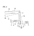
- a permanent magnet 19 serving as a magnetic substance is installed at a portion of a movable shade 13A opposed to the electromagnet 17 and that a switching device 18A is formed by the permanent magnet 19 and the electromagnet 17 as shown in FIG. 3 , for example.
- the permanent magnet 19 is provided as a component of the switching device 18A as described above, the drive force of the switching device 18A is increased, and the reliability of the action of the movable shade 13A can be improved.
- the movable shade 13A can be made of a material other than a magnetic material, such as a nonferrous metal or a resin, whereby the weight of the vehicle headlamp 1 can be reduced and the degree of freedom of selecting the material of the movable shade 13A can be improved.
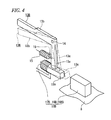
- the movable shades 13 and 13A are formed of the magnetic substance 16 and the permanent magnet 19, respectively, and the switching devices 18 and 18A are each formed by disposing the electromagnet 17 on the support member are described above, it may be possible that an electromagnet 17B is installed on a movable shade 13B and a magnetic substance 16B or a permanent magnet 19B serving as a magnetic substance is installed on the support member to form a switching device 18B as shown in FIG. 4 , for example. In this case, it is desirable that a winding portion 13c around which an electromagnet coil constituting the electromagnet 17B is wound is provided at the lower end portion of the movable shade 13B, for example.
- the vehicle headlamp 1 is provided with the switching device (18, 18A, 18B).
- the switching device 18 is formed of the magnetic substance 16 and the electromagnet 17, the switching device 18A is formed of the permanent magnet 19 and the electromagnet 17, and the switching device 18B is formed of the electromagnet 17B and the magnetic substance 16B.
- a link mechanism for connecting the movable shade (13, 13A, 13B) is not required.
- the mechanism of the vehicle headlamp 1 can be simplified due to the reduction in the number of components. Consequently, the production cost of the vehicle headlamp can be reduced and the size thereof can be made more compact.
- the movable shade (13, 13A, 13B) is held at the first position using the biasing spring 15
- the biasing spring 15 is not required.
- the mechanism of the vehicle headlamp 1 can be further simplified owing to further reduction in the number of components. Consequently, the production cost of the vehicle headlamp can be reduced further and the size thereof can be made even more compact.
Landscapes
- Engineering & Computer Science (AREA)
- General Engineering & Computer Science (AREA)
- Non-Portable Lighting Devices Or Systems Thereof (AREA)
Abstract
A vehicle headlamp (1) includes : a light source (11) that emits light; a reflector (10) that reflects the light emitted from the light source (11); a movable shade (13) that is movable between two positions, and that shields part of the light emitted from the light source (11); a support member (14,8) that movably supports the movable shade (13); and a switching device (18) that moves the movable shade (13) between the two positions, the switching device (18) including a magnetic substance (16) and an electromagnet (17). The magnetic substance (16) is disposed on one of the support member (14,8) and the movable shade (13), and the electromagnet (17) is disposed on the other one of the support member (14,8) and the movable shade (13).
Description
- An embodiment of the present invention relates to a vehicle headlamp. More specifically, the technical field of the embodiment relates to a vehicle headlamp in which a switching device having a magnetic substance and an electromagnet, each provided for a support member or a movable shade, is used to move the movable shade.
- Some vehicle headlamps have a structure in which a lamp unit having a light source is disposed inside an outer lamp housing formed of a cover and a lamp body, for example.
- This type of lamp unit is sometimes provided with, for example, a projection lens for projecting light emitted from a light source forward; a reflector for reflecting the light emitted from the light source toward the projection lens; a movable shade for shielding part of the light reflected by the reflector; and a switching device for switching the position of the movable shade disposed between the projection lens and the light source (see
JP-A-10-236222 - In a vehicle headlamp described in
JP-A-10-236222 - However, in the vehicle headlamp described in
JP-A-10-236222 - Furthermore, since the movable shade is connected to the solenoid via the link mechanism, positioning flexibility of the solenoid can be restricted, and the vehicle headlamp may become large in size.
- Accordingly, embodiments of the present invention may provide a vehicle headlamp having a lower production cost and a more compact size.
- In order to solve the above-described problem, a vehicle headlamp might be configured to include: a light source that emits light; a reflector that reflects the light emitted from the light source; a movable shade that is movable between two positions, and that shields part of the light emitted from the light source; a support member that movably supports the movable shade; and a switching device that moves the movable shade between the two positions, the switching device comprising a magnetic substance and an electromagnet, wherein the magnetic substance is disposed on one of the support member and the movable shade, and the electromagnet is disposed on the other one of the support member and the movable shade.
- Hence, no link mechanism is needed between the movable shade and the support member of the vehicle headlamp.
- According to a first aspect of the present invention, there is provided a vehicle headlamp including: a light source that emits light; a reflector that reflects the light emitted from the light source; a movable shade that is movable between two positions, and that shields part of the light emitted from the light source; a support member that movably supports the movable shade; and a switching device that moves the movable shade between the two positions, the switching device comprising a magnetic substance and an electromagnet, and, wherein the magnetic substance is disposed on one of the support member and the movable shade, and the electromagnet is disposed on the other one of the support member and the movable shade.
- Hence, a link mechanism for connecting the movable shade is not required. As a result, the mechanism of the vehicle headlamp may be simplified owing to the reduction in the number of components. Consequently, the production cost of the vehicle headlamp may be reduced and the size thereof may be made more compact.
- According to a second aspect of the invention, the magnetic substance may be disposed on the movable shade, and the electromagnet may be disposed on the support member.
- Hence, the arrangement of wires for supplying a drive current to the electromagnet can be made easy, whereby the mechanism can be simplified and the workability of the wiring work can be improved.
- According to a third aspect of the invention, the movable shade is formed from the magnetic substance.
- Hence, no magnetic substance other than the movable shade is necessary. Consequently, the production cost can be lowered due to the reduction in the number of components.
- According to a fourth aspect of the invention, a permanent magnet serves as the magnetic substance and is mounted on the movable shade.
- Hence, the drive force of the switching device can be increased, and the reliability of the action of the movable shade can be improved.
- A general configuration that implements the various features of embodiments of the present invention will be described with reference to the drawings. The drawings and the associated descriptions are provided to illustrate embodiments of the invention and should not limit the scope of the invention.
-
FIGS. 1 to 4 are views showing an exemplary embodiment of a vehicle headlamp according to the present invention; -
FIG. 1 is a schematic vertical sectional view showing the vehicle headlamp; -
FIG. 2 is an enlarged front view showing a switching device; -
FIG. 3 is an enlarged front view showing another switching device; and -
FIG. 4 is an enlarged perspective view showing still another switching device. - An exemplary embodiment showing a vehicle headlamp according to the present invention will be described below referring to the accompanying drawings.
- A
vehicle headlamp 1 is installed and provided at each of the left and right end portions in the front end portion of a vehicle body. - The
vehicle headlamp 1 is equipped with alamp body 2 having a concave portion opening forward and acover 3 for closing the opening area of thelamp body 2 as shown inFIG. 1 . Thelamp body 2 and thecover 3 form an outer lamp housing 4. The internal space of the outer lamp housing 4 is formed as alamp chamber 5. - A
mounting hole 2a passing through in the front-rear direction is formed at the rear end portion of thelamp body 2. A back cover 6 for closing themounting hole 2a is mounted at the rear end portion of thelamp body 2. - A
lamp unit 7 is disposed in thelamp chamber 5. Thelamp unit 7 has alens holder 8, aprojection lens 9 mounted at the front end portion of thelens holder 8, areflector 10 mounted on the rear face of thelens holder 8, and alight source 11 mounted at the rear end portion of thereflector 10. - A
fixed shade 8a disposed inside thelamp unit 7 is provided for thelens holder 8. Part of the light emitted from thelight source 11 is shielded by thefixed shade 8a. Thelens holder 8 serves as a support member for supporting a movable shade described later. - Supporting protruding
portions FIG. 1 ) protruding upward or downward are provided for thelens holder 8.Adjustment shafts portions adjustment shafts lamp body 2. - When one of the
adjustment shafts portion 8b for supporting the rotatedadjustment shaft 12 is moved in the front-rear direction, whereby thelamp unit 7 is tilted with respect to the outer lamp housing 4 based on the line connecting the other two supporting protrudingportions adjustment shafts lamp unit 7 is moved in the up-down direction or in the left-right direction with respect to thelamp body 2. Therefore it is possible to perform the optical axis adjustment (aiming adjustment) of the light emitted from thelight source 11. - Furthermore, when the connection shaft is moved in the front-rear direction, the supporting protruding
portion 8b for supporting the connection shaft is moved in the front-rear direction, whereby thelamp unit 7 is tilted with respect to the outer lamp housing 4 on the basis of the line connecting the other two supporting protrudingportions lamp unit 7 is moved in the up-down direction with respect to thelamp body 2, and thereby it is possible to perform the optical axis adjustment (leveling adjustment) of the light emitted from thelight source 11. - The front surface of the
projection lens 9 is formed into a convex face, and the rear surface thereof is formed into rearward directed flat face. When light is emitted from thelight source 11, theprojection lens 9 inverts an image that is formed on the focal plane containing the rear side focal point thereof and projects the image forward. - With the exception of the rear end portion thereof, the inner face of the
reflector 10 is formed as a reflectingsurface 10a. With the exception of the front end portion thereof, the reflectingsurface 10a is formed into, for example, a nearly elliptical spherical surface. The reflectingsurface 10a is formed so that its first focal point is located at the light-emitting portion (described later) of thelight source 11 and so that its second focal point is located at the rear side focal point of theprojection lens 9. The rear end portion of thereflector 10 is provided as amounting portion 10b having a nearly cylindrical shape. - The
light source 11 is, for example, a discharge bulb and emits light from a light-emittingportion 11b provided inside theouter pipe 11a thereof. Theouter pipe 11a is held at abase portion 11c disposed therebehind, and thebase portion 11c is mounted on themounting portion 10b of thereflector 10. - The light reflected by the
reflecting surface 10a of thereflector 10 is partially shielded by a movable shade (described later) and thefixed shade 8a and projected forward by theprojection lens 9. - Inside the
lamp unit 7, amovable shade 13 is disposed between theprojection lens 9 and thelight source 11 so as to be movable (rotatable) between a first position and a second position (seeFIG. 2 ). Themovable shade 13 is rotatable around asupport shaft 14 extending in the front-rear direction. Thesupport shaft 14 is supported by thelens holder 8. - The
movable shade 13 is formed of abase portion 13a extending in the up-down direction and a light-shieldingportion 13b protruding sideways from the upper end portion of thebase portion 13a, and the connection portion of thebase portion 13a and the light-shieldingportion 13b is supported by thesupport shaft 14. - One end of a biasing
spring 15 is connected to the lower end portion of thebase portion 13a of themovable shade 13. The other end of the biasingspring 15 is connected to, for example, the lower end portion of thelens holder 8. Hence, themovable shade 13 is biased by the biasingspring 15 in one of the rotating directions. In a state in which no external force is applied to themovable shade 13, it is held at the first position by the biasing force of the biasingspring 15. - The
movable shade 13 is formed by bending, for example, a magnetic metal material, such as an iron, so as to serve as amagnetic substance 16. - The first position (indicated by solid lines in
FIG. 2 ) of themovable shade 13 is a position in which a so-called low-beam light distribution pattern for short-distance irradiation is formed, for example. The second position (indicated by imaginary lines inFIG. 2 ) is a position in which a so-called high-beam light distribution pattern for long-distance irradiation is formed, for example. - An
electromagnet 17 having an electromagnetic coil is disposed on the side of the lower end portion of thebase portion 13a. The electromagnetic coil is connected to a power supply circuit (not shown). Theelectromagnet 17 is disposed on the inner face of the lower end portion of thelens holder 8 serving as the support member, for example. - Since the
electromagnet 17 is disposed on the support member and themovable shade 13 is formed of themagnetic substance 16 as described above, the arrangement of wires for supplying a drive current to theelectromagnet 17 is made easy, whereby the mechanism can be simplified and the workability of the wiring work can be improved. - Furthermore, since the
movable shade 13 is formed of themagnetic substance 16 as described above, it is not necessary to provide a magnetic substance other than themovable shade 13. It is thus possible to reduce the production cost by reducing the number of components. - The drive force of the
electromagnet 17 can be increased by inserting a core, such as an iron core, into the electromagnetic coil of theelectromagnet 17 and by disposing the core therein. - A switching
device 18 is formed by themagnetic substance 16 and theelectromagnet 17, and themovable shade 13 is rotated between the first position and the second position by the switchingdevice 18. - For example, in a state in which the
movable shade 13 is held at the first position by the biasing force of the biasingspring 15, when the drive current is supplied to the electromagnetic coil and theelectromagnet 17 is driven, the lower end portion of themovable shade 13 serving as themagnetic substance 16 is attracted toward theelectromagnet 17 and rotated around thesupport shaft 14 against the biasing force of the biasingspring 15 and then held at the second position (indicated by the imaginary lines inFIG. 2 ). - Furthermore, in a state in which the
movable shade 13 is held at the second position, when the supply of the drive current to the electromagnetic coil is stopped, themovable shade 13 is rotated around thesupport shaft 14 by the biasing force of the biasingspring 15 and held at the first position (indicated by the solid lines inFIG. 2 ). - Although an example in which the
movable shade 13 is formed of themagnetic substance 16 is described above, it may be possible that apermanent magnet 19 serving as a magnetic substance is installed at a portion of amovable shade 13A opposed to theelectromagnet 17 and that aswitching device 18A is formed by thepermanent magnet 19 and theelectromagnet 17 as shown inFIG. 3 , for example. - Since the
permanent magnet 19 is provided as a component of theswitching device 18A as described above, the drive force of theswitching device 18A is increased, and the reliability of the action of themovable shade 13A can be improved. - Furthermore, by the use of the
permanent magnet 19, themovable shade 13A can be made of a material other than a magnetic material, such as a nonferrous metal or a resin, whereby the weight of thevehicle headlamp 1 can be reduced and the degree of freedom of selecting the material of themovable shade 13A can be improved. - Moreover, although examples in which the
movable shades magnetic substance 16 and thepermanent magnet 19, respectively, and theswitching devices electromagnet 17 on the support member are described above, it may be possible that anelectromagnet 17B is installed on amovable shade 13B and amagnetic substance 16B or apermanent magnet 19B serving as a magnetic substance is installed on the support member to form aswitching device 18B as shown inFIG. 4 , for example. In this case, it is desirable that a windingportion 13c around which an electromagnet coil constituting theelectromagnet 17B is wound is provided at the lower end portion of themovable shade 13B, for example. - As described above, the
vehicle headlamp 1 is provided with the switching device (18, 18A, 18B). The switchingdevice 18 is formed of themagnetic substance 16 and theelectromagnet 17, theswitching device 18A is formed of thepermanent magnet 19 and theelectromagnet 17, and theswitching device 18B is formed of theelectromagnet 17B and themagnetic substance 16B. By virtue of the switching device, the movable shade (13, 13A, 13B) is moved (rotated) between the first position and the second position. - Hence, a link mechanism for connecting the movable shade (13, 13A, 13B) is not required. As a result, the mechanism of the
vehicle headlamp 1 can be simplified due to the reduction in the number of components. Consequently, the production cost of the vehicle headlamp can be reduced and the size thereof can be made more compact. - Moreover, although an example in which the movable shade (13, 13A, 13B) is held at the first position using the biasing
spring 15 is described above, it is possible to adopt a configuration in which the direction of the drive current to be supplied to the electromagnet coil of the electromagnet (17, 17B) is changed, and the movable shade (13, 13A, 13B) is held at the first position when the drive current is supplied to the electromagnet coil in one direction and the movable shade is held at the second position when the drive current is supplied to the electromagnet coil in the other direction, for example. - With this configuration, the biasing
spring 15 is not required. The mechanism of thevehicle headlamp 1 can be further simplified owing to further reduction in the number of components. Consequently, the production cost of the vehicle headlamp can be reduced further and the size thereof can be made even more compact. - The shapes and structures of the respective components described in the embodiment for carrying out the above-mentioned present invention are only a few examples for embodying the present invention, and these are not construed as limiting the technical scope of the present invention.
Claims (4)
- A vehicle headlamp comprising:a light source that emits light;a reflector that reflects the light emitted from the light source;a movable shade that is movable between two positions, and that shields part of the light emitted from the light source;a support member that movably supports the movable shade; anda switching device that moves the movable shade between the two positions, the switching device comprising a magnetic substance and an electromagnet, and ,wherein the magnetic substance is disposed on one of the support member and the movable shade, and the electromagnet is disposed on the other one of the support member and the movable shade.
- The vehicle headlamp according to claim 1, wherein
the magnetic substance is disposed on the movable shade, and
the electromagnet is provided disposed on the support member. - The vehicle headlamp according to claim 2, wherein
the movable shade is formed from the magnetic substance. - The vehicle headlamp according to claim 2, wherein
a permanent magnet serves as the magnetic substance and is mounted on the movable shade.
Applications Claiming Priority (1)
| Application Number | Priority Date | Filing Date | Title |
|---|---|---|---|
| JP2010156499A JP2012018862A (en) | 2010-07-09 | 2010-07-09 | Headlight for vehicle |
Publications (1)
| Publication Number | Publication Date |
|---|---|
| EP2405190A1 true EP2405190A1 (en) | 2012-01-11 |
Family
ID=44501578
Family Applications (1)
| Application Number | Title | Priority Date | Filing Date |
|---|---|---|---|
| EP11171903A Withdrawn EP2405190A1 (en) | 2010-07-09 | 2011-06-29 | Vehicle Headlamp |
Country Status (2)
| Country | Link |
|---|---|
| EP (1) | EP2405190A1 (en) |
| JP (1) | JP2012018862A (en) |
Cited By (2)
| Publication number | Priority date | Publication date | Assignee | Title |
|---|---|---|---|---|
| EP2966345A1 (en) * | 2014-07-09 | 2016-01-13 | AML Systems | Cut-off mechanism comprising a bar carrying a permanent magnet |
| WO2016097505A1 (en) * | 2014-12-18 | 2016-06-23 | Aml Systems | Cut-off mechanism including a strip actuated by an electromagnet comprising two air-gaps |
Families Citing this family (1)
| Publication number | Priority date | Publication date | Assignee | Title |
|---|---|---|---|---|
| WO2019230663A1 (en) * | 2018-05-31 | 2019-12-05 | 株式会社小糸製作所 | Light source unit |
Citations (5)
| Publication number | Priority date | Publication date | Assignee | Title |
|---|---|---|---|---|
| JPH10236222A (en) | 1997-02-24 | 1998-09-08 | Ichikoh Ind Ltd | Shade switching solenoid for vehicle lighting |
| DE19933415A1 (en) * | 1999-07-16 | 2001-01-18 | Kendrion Binder Magnete Gmbh | Headlamp for cars has pivoting screening device forming armature closing magnetic flux circuit generated by coil and it can be restored into home position |
| US6325528B1 (en) * | 1998-07-24 | 2001-12-04 | Robert Bosch Gmbh | Motor vehicle headlight assembly |
| EP1422472A2 (en) * | 2002-11-21 | 2004-05-26 | Valeo Vision | Elliptical vehicle headlamp emitting different light beams |
| DE102004025228A1 (en) * | 2004-05-22 | 2005-12-08 | Hella Kgaa Hueck & Co. | Headlamp for vehicle, has electrical actuator having spool as stator and spring unit for adjustment of rotor and aperture shaft in three predetermined rotary positions around same angle of rotation i.e. acute angle |
Family Cites Families (3)
| Publication number | Priority date | Publication date | Assignee | Title |
|---|---|---|---|---|
| JPS5868601U (en) * | 1981-11-04 | 1983-05-10 | トヨタ自動車株式会社 | vehicle headlights |
| DE19933414B4 (en) * | 1999-07-16 | 2005-02-03 | Automotive Lighting Reutlingen Gmbh | Headlight for motor vehicles |
| JP2010146985A (en) * | 2008-12-22 | 2010-07-01 | Koito Mfg Co Ltd | Headlight device for vehicle |
-
2010
- 2010-07-09 JP JP2010156499A patent/JP2012018862A/en active Pending
-
2011
- 2011-06-29 EP EP11171903A patent/EP2405190A1/en not_active Withdrawn
Patent Citations (5)
| Publication number | Priority date | Publication date | Assignee | Title |
|---|---|---|---|---|
| JPH10236222A (en) | 1997-02-24 | 1998-09-08 | Ichikoh Ind Ltd | Shade switching solenoid for vehicle lighting |
| US6325528B1 (en) * | 1998-07-24 | 2001-12-04 | Robert Bosch Gmbh | Motor vehicle headlight assembly |
| DE19933415A1 (en) * | 1999-07-16 | 2001-01-18 | Kendrion Binder Magnete Gmbh | Headlamp for cars has pivoting screening device forming armature closing magnetic flux circuit generated by coil and it can be restored into home position |
| EP1422472A2 (en) * | 2002-11-21 | 2004-05-26 | Valeo Vision | Elliptical vehicle headlamp emitting different light beams |
| DE102004025228A1 (en) * | 2004-05-22 | 2005-12-08 | Hella Kgaa Hueck & Co. | Headlamp for vehicle, has electrical actuator having spool as stator and spring unit for adjustment of rotor and aperture shaft in three predetermined rotary positions around same angle of rotation i.e. acute angle |
Cited By (5)
| Publication number | Priority date | Publication date | Assignee | Title |
|---|---|---|---|---|
| EP2966345A1 (en) * | 2014-07-09 | 2016-01-13 | AML Systems | Cut-off mechanism comprising a bar carrying a permanent magnet |
| CN105261441A (en) * | 2014-07-09 | 2016-01-20 | Aml系统公司 | Cut-off mechanism comprising a bar carrying a permanent magnet |
| CN105261441B (en) * | 2014-07-09 | 2019-01-18 | Aml系统公司 | Section retaining device including carrying the bar of permanent magnet |
| WO2016097505A1 (en) * | 2014-12-18 | 2016-06-23 | Aml Systems | Cut-off mechanism including a strip actuated by an electromagnet comprising two air-gaps |
| FR3030686A1 (en) * | 2014-12-18 | 2016-06-24 | Aml Systems | CUTTING MECHANISM COMPRISING A BAR ACTUATED BY A TWO GAP ELECTROSIMMER. |
Also Published As
| Publication number | Publication date |
|---|---|
| JP2012018862A (en) | 2012-01-26 |
Similar Documents
| Publication | Publication Date | Title |
|---|---|---|
| JP6034608B2 (en) | Vehicle headlamp | |
| CN103712145B (en) | Headlight for automobile | |
| JP6125767B2 (en) | Vehicle headlamp | |
| JP5414246B2 (en) | Vehicle headlamp | |
| CN104956146B (en) | Lamp unit for vehicle and headlamp for vehicle | |
| JP5700818B2 (en) | Vehicle headlamp | |
| JP2010218728A (en) | Vehicle headlamp | |
| EP2450236A1 (en) | Vehicle headlight | |
| JP6147510B2 (en) | Vehicle headlamp | |
| KR20110072381A (en) | Headlamp | |
| EP2527723A2 (en) | Vehicle headlamp and projection lens mounting method | |
| JP5688235B2 (en) | Beam switching device for rotary solenoid and vehicle headlamp | |
| JP2012018862A (en) | Headlight for vehicle | |
| JP2012059551A (en) | Vehicular headlight | |
| JP2011029121A (en) | Headlamp for vehicle | |
| JP6052973B2 (en) | Method for manufacturing lamp unit | |
| EP2103870B1 (en) | Vehicle headlamp | |
| JP2017204447A (en) | Vehicle lighting | |
| JP2013161586A (en) | Vehicular headlamp | |
| JP2013038023A (en) | Vehicular headlamp | |
| JP6153332B2 (en) | Vehicle headlamp | |
| JP6918899B2 (en) | Vehicle lighting unit | |
| JP2013243034A (en) | Vehicle headlight | |
| JP2015046341A (en) | Vehicle headlamp | |
| JP2004362993A (en) | Vehicle lighting |
Legal Events
| Date | Code | Title | Description |
|---|---|---|---|
| 17P | Request for examination filed |
Effective date: 20110718 |
|
| AK | Designated contracting states |
Kind code of ref document: A1 Designated state(s): AL AT BE BG CH CY CZ DE DK EE ES FI FR GB GR HR HU IE IS IT LI LT LU LV MC MK MT NL NO PL PT RO RS SE SI SK SM TR |
|
| AX | Request for extension of the european patent |
Extension state: BA ME |
|
| PUAI | Public reference made under article 153(3) epc to a published international application that has entered the european phase |
Free format text: ORIGINAL CODE: 0009012 |
|
| STAA | Information on the status of an ep patent application or granted ep patent |
Free format text: STATUS: THE APPLICATION HAS BEEN WITHDRAWN |
|
| 18W | Application withdrawn |
Effective date: 20160504 |