EP2405152A2 - Torque transmission device - Google Patents
Torque transmission device Download PDFInfo
- Publication number
- EP2405152A2 EP2405152A2 EP11172614A EP11172614A EP2405152A2 EP 2405152 A2 EP2405152 A2 EP 2405152A2 EP 11172614 A EP11172614 A EP 11172614A EP 11172614 A EP11172614 A EP 11172614A EP 2405152 A2 EP2405152 A2 EP 2405152A2
- Authority
- EP
- European Patent Office
- Prior art keywords
- cover
- ring
- peripheral surface
- groove
- transmission device
- Prior art date
- Legal status (The legal status is an assumption and is not a legal conclusion. Google has not performed a legal analysis and makes no representation as to the accuracy of the status listed.)
- Granted
Links
- 230000005540 biological transmission Effects 0.000 title claims description 38
- 230000002093 peripheral effect Effects 0.000 claims abstract description 77
- 239000000314 lubricant Substances 0.000 description 5
- 238000009434 installation Methods 0.000 description 3
- 230000000903 blocking effect Effects 0.000 description 2
- 230000013011 mating Effects 0.000 description 2
- 238000010276 construction Methods 0.000 description 1
- 230000006866 deterioration Effects 0.000 description 1
- 238000012986 modification Methods 0.000 description 1
- 230000004048 modification Effects 0.000 description 1
- 230000002265 prevention Effects 0.000 description 1
- 238000005086 pumping Methods 0.000 description 1
- 230000001105 regulatory effect Effects 0.000 description 1
- 238000007789 sealing Methods 0.000 description 1
- 238000009751 slip forming Methods 0.000 description 1
- 239000004575 stone Substances 0.000 description 1
Images



Classifications
-
- F—MECHANICAL ENGINEERING; LIGHTING; HEATING; WEAPONS; BLASTING
- F16—ENGINEERING ELEMENTS AND UNITS; GENERAL MEASURES FOR PRODUCING AND MAINTAINING EFFECTIVE FUNCTIONING OF MACHINES OR INSTALLATIONS; THERMAL INSULATION IN GENERAL
- F16D—COUPLINGS FOR TRANSMITTING ROTATION; CLUTCHES; BRAKES
- F16D3/00—Yielding couplings, i.e. with means permitting movement between the connected parts during the drive
- F16D3/02—Yielding couplings, i.e. with means permitting movement between the connected parts during the drive adapted to specific functions
- F16D3/06—Yielding couplings, i.e. with means permitting movement between the connected parts during the drive adapted to specific functions specially adapted to allow axial displacement
-
- F—MECHANICAL ENGINEERING; LIGHTING; HEATING; WEAPONS; BLASTING
- F16—ENGINEERING ELEMENTS AND UNITS; GENERAL MEASURES FOR PRODUCING AND MAINTAINING EFFECTIVE FUNCTIONING OF MACHINES OR INSTALLATIONS; THERMAL INSULATION IN GENERAL
- F16D—COUPLINGS FOR TRANSMITTING ROTATION; CLUTCHES; BRAKES
- F16D3/00—Yielding couplings, i.e. with means permitting movement between the connected parts during the drive
- F16D3/84—Shrouds, e.g. casings, covers; Sealing means specially adapted therefor
- F16D3/843—Shrouds, e.g. casings, covers; Sealing means specially adapted therefor enclosed covers
- F16D3/848—Shrouds, e.g. casings, covers; Sealing means specially adapted therefor enclosed covers allowing relative movement of joint parts due to sliding between parts of the cover
Definitions
- the present invention relates to a torque transmission device.
- the torque transmission device used in a joint of a propeller shaft provided in a vehicle is, for example, disclosed in Japanese Patent Application Publication No. 62-110628 ( JP-A-62-110628 ).
- This torque transmission device includes, as shown in FIG. 6 : a shaft 81 that has a male spline 81a in a part of an outer periphery; a sleeve 82 that has a female spline 82a fitted to the male spline 81a in a part of an inner periphery; a cylindrical cover 83 that is attached to a base portion 81b of the shaft 81 and covers an outer pheriphry of the sleeve 82; and a seal 84 that has a rubber seal lip for sealing an annular space formed between the cover 83 and the sleeve 82.
- the shaft 81 and the sleeve 82 are incapable of relative rotation in a circumferential direction, but capable of relative movement in an axial direction, by means of the male spline 81a and the female spline 82a.
- the torque transmission device When, specifically, the torque transmission device is used as a joint of a propeller shaft, an incoming obstacle from road (such as a small stone) may hit the seal 84, and therefore it may cause the breakage of the seal 84.
- a structure as shown in FIG. 7 has been proposed such that a second cover 85 that has a cylindrical shape and that coves the seal 84 as well as the cover (first cover) 83 from radially outside is attached to the sleeve 82.
- the related art can protect the seal 84 from hitting by the incoming obstacle from the outside, the obstacle such as mud and small dirt may get in the inside where the seal 84 is provided through a gap between an inner peripheral surface of the second cover 85 and an outer peripheral surface of the first cover 83.
- the seal 84 with the rubber seal lip prevents the obstacle from entering in a spline portion 86, the obstacle may accumulate in the vicinity of the seal 84, and the accumulated obstacles may eventually cause the breakage and deterioration of the seal 84.
- a structure is conceived such that, besides the seal 84 (first seal), the second seal having the same rubber seal lip as the first seal 84 is provided between the outer peripheral surface of the first cover 83 and the inner peripheral surface of the second cover.
- the seal 84 first seal
- the volume of the sealed space that is formed between the first seal 84 and the second seal may vary, and the space may be subjected to negative pressure.
- lubricant in the spline portion 86 may be drawn to the annular space between the sleeve 82 and the first cover 83 or sucked outside over the seal 84.
- lubricant shortage in the spline portion 86 may occur.
- the present invention provides a torque transmission device that is capable of preventing the entry of obstacles from the outside to the inside, and that does not produce negative pressure inside when the shaft and the sleeve relatively move in the axial direction.
- a first aspect of the invention relates to a torque transmission device including: a shaft that has a male spline on a part of an outer periphery thereof; a sleeve that has a female spline fitted to the male spline on a part of an inner periphery thereof and that is incapable of relative rotation about the shaft and capable of relative movement in an axial direction; a first cover that has a cylindrical shape and that is attached to the shaft and covers an outer periphery of the sleeve; a second cover that has a cylindrical shape and that is attached to the sleeve and covers an outer periphery of the first cover; and a seal that fills an annular space between the first cover and the sleeve.
- the torque transmission device further includes: a ring that is installed in a circumferentially continuous groove formed in one of an outer peripheral surface of the first cover and an inner peripheral surface of the second cover, and that is slidable on the other one of the outer peripheral surface of the first cover and the inner peripheral surface of the second cover.
- a labyrinth seal is constructed between the ring and the groove.
- a labyrinth seal is constructed between the outer peripheral surface of the first cover and the inner peripheral surface of the second cover by the ring and the groove. Therefore, the entry of obstacles from the outside to the side of the seal can be prevented.
- the ring mounted in the groove formed in one side of the outer peripheral surface of the first cover and the inner peripheral surface of the second cover is slidable on the other side surface of the outer peripheral surface of the first cover and the inner peripheral surface of the second cover, and therefore the ring does not interrupt the relative axial movement between the first cover and the second cover or the relative axial movement between the shaft and the sleeve.
- the device according to the present invention permits the passage of air but regulates the passage of obstacles such as mud between the first cover and the second cover.
- the ring may be a C-shaped ring in which a part of a circumference is separated.
- the installation of the ring to the groove is facilitated.
- multiple C-shaped rings may be provided in the groove in the axial direction, and circumferential positions of separating portions of the C-shaped rings are different from each other.
- the C-shaped ring has a separating portion in a part of the circumference.
- obstacles such as mud may pass through the separating portion
- multiple rings are provided in the axial direction, and the circumferential positions of the separating portions are different from each other. Therefore, the multiple rings are capable of blocking the passage of the obstacles. In other words, the installation of the ring can be performed more easily, and prevention performance against the entry of obstacles can be secured.
- the groove may be formed in the outer peripheral surface of the first cover.
- An outer peripheral surface of the ring may contact the inner peripheral surface of the second cover.
- a gap may be formed between an inner peripheral surface of the ring and a bottom surface of the groove.
- the gap may be smaller than a gap that is formed between the outer peripheral surface of the first cover and the inner peripheral surface of the second cover.
- the groove may be formed in the inner peripheral surface of the second cover.
- a gap may be formed between the outer peripheral surface of the ring and a bottom surface of the groove.
- the outer peripheral surface of the ring may have a gap between the outer peripheral surface and a bottom surface of the groove.
- the gap may be smaller than a gap that is formed between the outer peripheral surface of the first cover and the inner peripheral surface of the second cover.
- an axial width of the groove may be larger than a thickness of the ring.
- a difference between the axial width of the groove and the thickness of the ring may be smaller than a gap that is formed between the outer peripheral surface of the first cover and the inner peripheral surface of the second cover.
- a mechanism that reduces airtightness may be provided in at least one of a side surface of the groove and a side surface of the ring.
- the mechanism may be provided through rough surface processing.
- the mechanism may be a projection that is provided in at least one of the side surface of the groove and the side surface of the ring.
- the ring may be a C-shaped ring that a part of a circumference is separated.
- the mechanism may be formed by misalignment of separating portions of the ring in the axial direction.
- the mechanism may be a notch that is formed in the ring.
- the passage of air is permitted, but the passage of obstacles such as mud can be regulated between the first cover and the second cover. Therefore, the entry of obstacles from the outside can be prevented, and negative pressure, which can be produced in the related art, is not produced inside when the shaft and the sleeve relatively move in the axial direction. As a result, it is possible to prevent, for example, that lubricant in the spline is sucked outside.
- FIG. 1 is a vertical cross-sectional view illustrating a torque transmission device according to the first embodiment of the present invention and shows an upper half of the torque transmission device.
- the torque transmission device of this embodiment may be applicable to a joint of the propeller shaft of the vehicle.
- the torque transmission device of FIG. 1 includes a shaft 1 that has a male spline 2 on a part of the outer periphery, and a sleeve 6 that has a female spline 7 fitted to the male spline 2 on a part of the inner periphery.
- FIG. 1 shows the most contracted state of the device.
- the shaft 1 mentioned above has a shaft body 4 on which the male spline 2 is formed and a base portion 3 that has a larger diameter than the shaft body 4.
- the shaft body 4 extends in an axial direction from the base portion 3 (to the left side in the axial direction, in this embodiment).
- the base portion 3 and the shaft body 4 are formed as one-piece.
- the sleeve 6 mentioned above has a base portion 9 and a cylindrical portion 8 on which the female spline 7 is formed.
- the cylindrical portion 8 extends in an axial direction from the base portion 9 (to the right side in the axial direction, in this embodiment).
- the base portion 9 and the cylindrical portion 8 are formed as one-piece.
- the torque transmission device also includes a first cover 10 that has a straight cylindrical shape and that covers an outer pherphly of the cylindrical portion 8 of the sleeve 6, and a second cover 20 that has a straight cylindrical shape and that covers an outer pherphly of the first cover 10. All of the shaft 1, sleeve 6, the first cover 10, and the second cover 20 have circular cross sections and are arranged concentrically.
- the first cover 10 mentioned above is fixed to the base portion 3 of the shaft 1 at one end (at a right base portion 10b in FIG. 1 ).
- An annular space is formed between the first cover 10 and the shaft body 4 of the shaft 1 such that the side of the fitting portion (base portion 10b) of the first cover 10 is closed.
- the second cover 20 mentioned above is fixed to the cylindrical portion 8 of the sleeve 6 at one end (at a left base portion 20b in FIG. 1 ).
- An annular space is formed between the second cover 20 and the cylindrical portion 8 of the sleeve 6 such that the side of the fitting portion (base portion 20b) of the second cover 20 is closed.
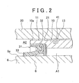
- FIG. 2 is an enlarged cross-sectional view illustrating the seal 31 and a ring 41 described below.
- the seal 31 has a body portion 32 that is fixed to the first cover 10 and a seal lip 33 that extends from the body portion 32 to an outer peripheral surface 8a of the cylindrical portion 8 of the sleeve 6.
- the seal lip 33 is made of rubber, for example. Referring to FIGs. 1 and 2 , when the shaft 1 and the sleeve 6 relatively move in an axial direction, the sleeve 6 and the first cover 10 fixed to the shaft 1 relatively move in the axial direction. In this case, the seal lip 33 slides on an outer peripheral surface 8a of the cylindrical portion 8 of the sleeve 6.
- the seal 31 is mounted to a tip 10a of the first cover10 and seals the annular space A formed between the first cover 10 and the cylindrical portion 8 at the side of the tip 10a. That is, in FIG. 1 , the seal 31 divides, along with the first cover 10, a radial inward space of the second cover 20 into the annular space A1 as the inner side and an annular space A2 as the outer side.
- the annular space A1 is a space that is formed between the first cover 10 and the cylindrical portion 8 of the sleeve 6
- the annular space A2 is a space that is formed at the side between the base portion 20b of the second cover 20 and the base portion of the cylindrical portion 8 of the sleeve 6.
- a circumferentially continuous groove 13 is formed in an outer peripheral surface 11 of the first cover 10.
- This groove 13 is continuously formed throughout the perimeter of the outer peripheral surface 11 as an annular groove.
- the ring 41 is arranged within the groove 13. While the ring 41 has an annular shape, this embodiment employs a C-shaped ring in order to facilitate the installation of the ring to the groove 13.
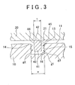
- FIG. 3 is a cross-sectional view illustrating the ring 41 and the groove 13.
- the ring 41 is arranged between side surfaces 14 and 15 that are located on both sides in the axial direction of the groove 13 that is formed in the first cover 10. However, the ring 41 is not fixed to the first cover 10 and is movable inside the groove 13 in the axial direction.
- An outer peripheral surface 42 of the ring 41 closely contacts an inner peripheral surface 21 of the second cover 20. That is, the ring 41 is being urged against the inner peripheral surface 21 of the second cover 20.
- the ring 41 has an axial thickness t that is smaller than a width dimension w of the groove 13 (w > t).
- the ring 41 has a gap gl with a bottom surface 16 of the groove 13 and is disposed between the side surfaces 14 and 15 of the groove 13.
- a labyrinth seal (labyrinth structure) is constructed between the outer peripheral surface 11 of the first cover 10 and the inner peripheral surface 21 of the second cover 20.
- the labyrinth seal is capable of preventing the entry of obstacles from an opening of a tip 20a of the second cover 20 (see FIG. 1 ) to the seal 31.
- the ring 41 mounted in the groove 13 may be slidable on the inner peripheral surface 21 of the second cover 20 and therefore may not interrupt the relative axial movement between the first cover 10 and the second cover 20 or the relative axial movement between the shaft 1 and the sleeve 6.
- the gap g1 is formed between an inner peripheral surface 43 of the ring 41 and the bottom surface 16 of the groove 13, and gaps g2 and g3 may be formed between side surfaces 44 and 45 of the ring 41 and the side surfaces 14 and 15 of the groove 13, respectively. Air can pass through the gaps g1, g2, and g3. Therefore, assuming that the labyrinth seal formed by the ring 41 and the groove 13 is a second seal, when the shaft 1 and the sleeve 6 relatively move in the axial direction, negative pressure is not produced in a space between the second seal and the seal 31 (first seal).
- lubricant for example, that exists in the mating portion of the male spline 2 with the female spline 7 may not be drawn to the annular space A1 between the cylindrical portion 8 of the sleeve 6 and the first cover 10 or sucked out to the annular space A2 formed on the side of the base portion 20b of the second cover 20 over the seal 31, by the negative pressure. Therefore, lubricant shortage in the mating portion of the splines 2 and 7 can be prevented.
- each of the gaps g1, g2, and g3 may be set to the size smaller than the gap that is formed between the outer peripheral surface 11 of the first cover 10 and the inner peripheral surface 21 of the second cover 20.
- the ring 41 fitted inside the groove 13 formed in the first cover 10 is pushed to one of the side surfaces 14 and 15 of the groove 13 and slides on the inner peripheral surface 21 of the second cover 20.
- one of the side surfaces 44 and 45 of the ring 41 is in contact with one of the side surfaces 14 and 15 of the groove 13; however, the ring 41 is a C-shaped ring and therefore does not have airtightness between the contacting side surfaces, so that the passage of air is permitted.
- rough surface processing may be applied to one or both of the side surfaces 14 and 15 of the groove 13 and the side surfaces 44 and 45 of the ring 41.
- one or more projections may be provided in one or both of the side surfaces 14 and 15 of the groove 13 and the side surfaces 44 and 45 of the ring 41. Separating portions of the ring 41 formed in C-shape may be misaligned in the axial direction. Furthermore, a notch may be formed on the outer peripheral surface of the ring 41 in order to reduce the airtightness.
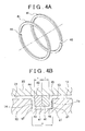
- FIGs. 4A and 4B show a second embodiment that includes multiple rings 41.
- two rings 41 are both disposed inside the groove 13 in an axially aligned manner.
- each ring 41 is a C-shaped ring that a part of the circumference is separated as shown in FIG. 4A , and the C-shaped rings 41 and 41 have different circumferential positions of the separating portions (absent portions) 46 in a fitting state to the groove 13.
- the rings 41 and 41 are mounted in the groove such that the separating portions 46 and 46 of the two rings 41 and 41 are offset by 180 degrees.
- the C-shaped ring 41 is employed, and therefore the separating portion 46 is provided in a part of the circumference of the ring 41.
- this embodiment includes multiple rings 41 in the axial direction, and the circumferential positions of the separating portions 46 are different from each other. Therefore, the rings 41 and 41 are capable of blocking the passage of the obstacles.
- the width dimension w of the groove 13 and the thickness t of the ring 41 is set to have a relationship (w > 2 ⁇ t) so that gaps are formed between the rings 41 and 41 and the groove 13.
- the groove 13 may be formed in one side of the outer peripheral surface 11 of the first cover 10 and the inner peripheral surface 21 of the second cover 20, and the ring 41 may be slidable on the other side of the outer peripheral surface 11 of the first, cover 10 and the inner peripheral surface 21 of the second cover 20.
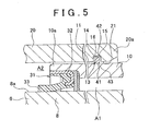
- the groove 13 may be formed in the inner peripheral surface 21 of the second cover 20, and the ring 41 mounted in the groove 13 may be slidable on the outer peripheral surface 11 of the first cover 10.
- a forming surface of the groove 13 and a sliding surface of the ring 41 are inverted.
- the groove 13 shown in FIG. 2 is formed on the side of the tip 10a of the first cover 10 (left side of FIG. 1 ), but the groove 13 shown in FIG. 5 is required to be formed on the side of the tip 20a of the second cover 20.
- the ring 41 is arranged between side surfaces 14 and 15 that are located on both sides in the axial direction of the groove 13 that is formed in the second cover 20.
- the ring 41 is not fully fixed in position to the second cover 20 and is movable inside the groove 13 in the axial direction.
- An inner peripheral surface 43 of the ring 41 closely contacts an outer peripheral surface 11 of the first cover 10. That is, the ring 41 is being urged against the outer peripheral surface 11 of the first cover 10.
- a labyrinth seal is constructed between the outer peripheral surface 11 of the first cover 10 and the inner peripheral surface 21 of the second cover 20 and therefore is capable of preventing the entry of obstacles from an opening of a tip 20a of the second cover 20 to the seal 31.
- the ring 41 mounted in the groove 13 may be slidable on the outer peripheral surface 11 of the first cover 10 and therefore may not interrupt the relative axial movement between the first cover 10 and the second cover 20 or the relative axial movement between the shaft 1 and the sleeve 6.
Landscapes
- Engineering & Computer Science (AREA)
- General Engineering & Computer Science (AREA)
- Mechanical Engineering (AREA)
- Sealing Using Fluids, Sealing Without Contact, And Removal Of Oil (AREA)
- Sealing Devices (AREA)
Abstract
Description
- The present invention relates to a torque transmission device.
- The torque transmission device used in a joint of a propeller shaft provided in a vehicle is, for example, disclosed in Japanese Patent Application Publication No.
62-110628 JP-A-62-110628 FIG. 6 : ashaft 81 that has amale spline 81a in a part of an outer periphery; asleeve 82 that has afemale spline 82a fitted to themale spline 81a in a part of an inner periphery; acylindrical cover 83 that is attached to abase portion 81b of theshaft 81 and covers an outer pheriphry of thesleeve 82; and aseal 84 that has a rubber seal lip for sealing an annular space formed between thecover 83 and thesleeve 82. In this torque transmission device, theshaft 81 and thesleeve 82 are incapable of relative rotation in a circumferential direction, but capable of relative movement in an axial direction, by means of themale spline 81a and thefemale spline 82a. - When, specifically, the torque transmission device is used as a joint of a propeller shaft, an incoming obstacle from road (such as a small stone) may hit the
seal 84, and therefore it may cause the breakage of theseal 84. For this reason, a structure as shown inFIG. 7 has been proposed such that asecond cover 85 that has a cylindrical shape and that coves theseal 84 as well as the cover (first cover) 83 from radially outside is attached to thesleeve 82. - According to the structure of
FIG. 7 , although the related art can protect theseal 84 from hitting by the incoming obstacle from the outside, the obstacle such as mud and small dirt may get in the inside where theseal 84 is provided through a gap between an inner peripheral surface of thesecond cover 85 and an outer peripheral surface of thefirst cover 83. In this case, although theseal 84 with the rubber seal lip prevents the obstacle from entering in aspline portion 86, the obstacle may accumulate in the vicinity of theseal 84, and the accumulated obstacles may eventually cause the breakage and deterioration of theseal 84. - Therefore, a structure is conceived such that, besides the seal 84 (first seal), the second seal having the same rubber seal lip as the
first seal 84 is provided between the outer peripheral surface of thefirst cover 83 and the inner peripheral surface of the second cover. However, in the structure that is provided with the seal, when theshaft 81 and thesleeve 82 relatively move in the axial direction, the volume of the sealed space that is formed between thefirst seal 84 and the second seal may vary, and the space may be subjected to negative pressure. In this case, due to a pumping action based on the negative pressure, lubricant in thespline portion 86 may be drawn to the annular space between thesleeve 82 and thefirst cover 83 or sucked outside over theseal 84. Thus, lubricant shortage in thespline portion 86 may occur. - The present invention provides a torque transmission device that is capable of preventing the entry of obstacles from the outside to the inside, and that does not produce negative pressure inside when the shaft and the sleeve relatively move in the axial direction.
- A first aspect of the invention relates to a torque transmission device including: a shaft that has a male spline on a part of an outer periphery thereof; a sleeve that has a female spline fitted to the male spline on a part of an inner periphery thereof and that is incapable of relative rotation about the shaft and capable of relative movement in an axial direction; a first cover that has a cylindrical shape and that is attached to the shaft and covers an outer periphery of the sleeve; a second cover that has a cylindrical shape and that is attached to the sleeve and covers an outer periphery of the first cover; and a seal that fills an annular space between the first cover and the sleeve. The torque transmission device further includes: a ring that is installed in a circumferentially continuous groove formed in one of an outer peripheral surface of the first cover and an inner peripheral surface of the second cover, and that is slidable on the other one of the outer peripheral surface of the first cover and the inner peripheral surface of the second cover. A labyrinth seal is constructed between the ring and the groove.
- According to the above aspect, a labyrinth seal is constructed between the outer peripheral surface of the first cover and the inner peripheral surface of the second cover by the ring and the groove. Therefore, the entry of obstacles from the outside to the side of the seal can be prevented. The ring mounted in the groove formed in one side of the outer peripheral surface of the first cover and the inner peripheral surface of the second cover is slidable on the other side surface of the outer peripheral surface of the first cover and the inner peripheral surface of the second cover, and therefore the ring does not interrupt the relative axial movement between the first cover and the second cover or the relative axial movement between the shaft and the sleeve.
- In the labyrinth seal, air can pass through the gap that is formed between the ring and the groove. Therefore, when the shaft and the sleeve relatively move in the axial direction, negative pressure, which can be produced in the related art, is not produced inside. That is, the device according to the present invention permits the passage of air but regulates the passage of obstacles such as mud between the first cover and the second cover.
- In the above aspect, the ring may be a C-shaped ring in which a part of a circumference is separated.
- According to the above aspect, the installation of the ring to the groove is facilitated.
- In the above aspect, multiple C-shaped rings may be provided in the groove in the axial direction, and circumferential positions of separating portions of the C-shaped rings are different from each other.
- According to the above aspect, the C-shaped ring has a separating portion in a part of the circumference. Although obstacles such as mud may pass through the separating portion, multiple rings are provided in the axial direction, and the circumferential positions of the separating portions are different from each other. Therefore, the multiple rings are capable of blocking the passage of the obstacles. In other words, the installation of the ring can be performed more easily, and prevention performance against the entry of obstacles can be secured.
- In the above aspect, the groove may be formed in the outer peripheral surface of the first cover. An outer peripheral surface of the ring may contact the inner peripheral surface of the second cover. A gap may be formed between an inner peripheral surface of the ring and a bottom surface of the groove.
- In the above aspect, the gap may be smaller than a gap that is formed between the outer peripheral surface of the first cover and the inner peripheral surface of the second cover. The groove may be formed in the inner peripheral surface of the second cover. A gap may be formed between the outer peripheral surface of the ring and a bottom surface of the groove.
- In the above aspect, the outer peripheral surface of the ring may have a gap between the outer peripheral surface and a bottom surface of the groove.
- In the above aspect, the gap may be smaller than a gap that is formed between the outer peripheral surface of the first cover and the inner peripheral surface of the second cover.
- In the above aspect, an axial width of the groove may be larger than a thickness of the ring.
- In the above aspect, a difference between the axial width of the groove and the thickness of the ring may be smaller than a gap that is formed between the outer peripheral surface of the first cover and the inner peripheral surface of the second cover.
- In the above aspect, a mechanism that reduces airtightness may be provided in at least one of a side surface of the groove and a side surface of the ring.
- In the above aspect, the mechanism may be provided through rough surface processing.
- In the above aspect, the mechanism may be a projection that is provided in at least one of the side surface of the groove and the side surface of the ring.
- In the above aspect, the ring may be a C-shaped ring that a part of a circumference is separated. The mechanism may be formed by misalignment of separating portions of the ring in the axial direction.
- In the above aspect, the mechanism may be a notch that is formed in the ring.
- According to the above aspect, the passage of air is permitted, but the passage of obstacles such as mud can be regulated between the first cover and the second cover. Therefore, the entry of obstacles from the outside can be prevented, and negative pressure, which can be produced in the related art, is not produced inside when the shaft and the sleeve relatively move in the axial direction. As a result, it is possible to prevent, for example, that lubricant in the spline is sucked outside.
- Features, advantages, and technical and industrial significance of exemplary embodiments of the invention will be described below with reference to the accompanying drawings, in which like numerals denote like elements, and wherein:
-
FIG. 1 is a vertical cross-sectional view illustrating a torque transmission device according to the first embodiment of the present invention and shows an upper half of the torque transmission device; -
FIG. 2 is an enlarged cross-sectional view illustrating a seal and a ring; -
FIG. 3 is a cross-sectional view illustrating a ring and a groove; -
FIG. 4A and FIG. 4B illustrate a state that two rings are mounted in the groove; -
FIG. 5 is an enlarged cross-sectional view illustrating a part of the torque transmission device according to the second embodiment of the present invention; -
FIG. 6 is a vertical cross-sectional view illustrating a torque transmission device according to the related art; and -
FIG. 7 is a vertical cross-sectional view illustrating a torque transmission device according to the related art. - The first embodiment of the present invention is described hereinafter with reference to the attached drawings.
FIG. 1 is a vertical cross-sectional view illustrating a torque transmission device according to the first embodiment of the present invention and shows an upper half of the torque transmission device. The torque transmission device of this embodiment may be applicable to a joint of the propeller shaft of the vehicle. The torque transmission device ofFIG. 1 includes a shaft 1 that has amale spline 2 on a part of the outer periphery, and asleeve 6 that has afemale spline 7 fitted to themale spline 2 on a part of the inner periphery. By means of thesplines sleeve 6 are incapable of relative rotation, but capable of mutual torque transmission and further relative movement in the axial direction, so that the total length of the device including the shaft 1 and thesleeve 6 may be expanded and contracted.FIG. 1 shows the most contracted state of the device. - The shaft 1 mentioned above has a
shaft body 4 on which themale spline 2 is formed and abase portion 3 that has a larger diameter than theshaft body 4. Theshaft body 4 extends in an axial direction from the base portion 3 (to the left side in the axial direction, in this embodiment). Thebase portion 3 and theshaft body 4 are formed as one-piece. Thesleeve 6 mentioned above has abase portion 9 and acylindrical portion 8 on which thefemale spline 7 is formed. Thecylindrical portion 8 extends in an axial direction from the base portion 9 (to the right side in the axial direction, in this embodiment). Thebase portion 9 and thecylindrical portion 8 are formed as one-piece. - In
FIG.1 , the torque transmission device also includes afirst cover 10 that has a straight cylindrical shape and that covers an outer pherphly of thecylindrical portion 8 of thesleeve 6, and asecond cover 20 that has a straight cylindrical shape and that covers an outer pherphly of thefirst cover 10. All of the shaft 1,sleeve 6, thefirst cover 10, and thesecond cover 20 have circular cross sections and are arranged concentrically. - The
first cover 10 mentioned above is fixed to thebase portion 3 of the shaft 1 at one end (at aright base portion 10b inFIG. 1 ). An annular space is formed between thefirst cover 10 and theshaft body 4 of the shaft 1 such that the side of the fitting portion (base portion 10b) of thefirst cover 10 is closed. Thesecond cover 20 mentioned above is fixed to thecylindrical portion 8 of thesleeve 6 at one end (at aleft base portion 20b inFIG. 1 ). An annular space is formed between thesecond cover 20 and thecylindrical portion 8 of thesleeve 6 such that the side of the fitting portion (base portion 20b) of thesecond cover 20 is closed. - Furthermore, the torque transmission device is provided with a
seal 31 that seals the annular space A1 between thefirst cover 10 and thecylindrical portion 8 of thesleeve 6.FIG. 2 is an enlarged cross-sectional view illustrating theseal 31 and aring 41 described below. Theseal 31 has abody portion 32 that is fixed to thefirst cover 10 and aseal lip 33 that extends from thebody portion 32 to an outerperipheral surface 8a of thecylindrical portion 8 of thesleeve 6. Theseal lip 33 is made of rubber, for example. Referring toFIGs. 1 and2 , when the shaft 1 and thesleeve 6 relatively move in an axial direction, thesleeve 6 and thefirst cover 10 fixed to the shaft 1 relatively move in the axial direction. In this case, theseal lip 33 slides on an outerperipheral surface 8a of thecylindrical portion 8 of thesleeve 6. - The
seal 31 is mounted to atip 10a of the first cover10 and seals the annular space A formed between thefirst cover 10 and thecylindrical portion 8 at the side of thetip 10a. That is, inFIG. 1 , theseal 31 divides, along with thefirst cover 10, a radial inward space of thesecond cover 20 into the annular space A1 as the inner side and an annular space A2 as the outer side. Here, the annular space A1 is a space that is formed between thefirst cover 10 and thecylindrical portion 8 of thesleeve 6, and the annular space A2 is a space that is formed at the side between thebase portion 20b of thesecond cover 20 and the base portion of thecylindrical portion 8 of thesleeve 6. When the whole device is expanded or contracted, theseal 31 is in a covered state from the radial outward by thesecond cover 20 throughout a stroke length of the device. - As shown in
FIG. 2 , a circumferentiallycontinuous groove 13 is formed in an outerperipheral surface 11 of thefirst cover 10. Thisgroove 13 is continuously formed throughout the perimeter of the outerperipheral surface 11 as an annular groove. Thering 41 is arranged within thegroove 13. While thering 41 has an annular shape, this embodiment employs a C-shaped ring in order to facilitate the installation of the ring to thegroove 13. -
FIG. 3 is a cross-sectional view illustrating thering 41 and thegroove 13. Thering 41 is arranged between side surfaces 14 and 15 that are located on both sides in the axial direction of thegroove 13 that is formed in thefirst cover 10. However, thering 41 is not fixed to thefirst cover 10 and is movable inside thegroove 13 in the axial direction. An outerperipheral surface 42 of thering 41 closely contacts an innerperipheral surface 21 of thesecond cover 20. That is, thering 41 is being urged against the innerperipheral surface 21 of thesecond cover 20. Therefore, when the shaft 1 and thesleeve 6 relatively move in the axial direction, thefirst cover 10 and thesecond cover 20 relatively move in the axial direction also, and thus thering 41 fitted inside thegroove 13 formed in thefirst cover 10 is pushed to one of the side surfaces 14 and 15 of thegroove 13 and slides on the innerperipheral surface 21 of thesecond cover 20. - As shown in
FIG. 3 , thering 41 has an axial thickness t that is smaller than a width dimension w of the groove 13 (w > t). In addition, thering 41 has a gap gl with abottom surface 16 of thegroove 13 and is disposed between the side surfaces 14 and 15 of thegroove 13. By thering 41 and thegroove 13, a labyrinth seal (labyrinth structure) is constructed between the outerperipheral surface 11 of thefirst cover 10 and the innerperipheral surface 21 of thesecond cover 20. The labyrinth seal is capable of preventing the entry of obstacles from an opening of atip 20a of the second cover 20 (seeFIG. 1 ) to theseal 31. - The
ring 41 mounted in thegroove 13 may be slidable on the innerperipheral surface 21 of thesecond cover 20 and therefore may not interrupt the relative axial movement between thefirst cover 10 and thesecond cover 20 or the relative axial movement between the shaft 1 and thesleeve 6. - In this labyrinth seal, the gap g1 is formed between an inner
peripheral surface 43 of thering 41 and thebottom surface 16 of thegroove 13, and gaps g2 and g3 may be formed between side surfaces 44 and 45 of thering 41 and the side surfaces 14 and 15 of thegroove 13, respectively. Air can pass through the gaps g1, g2, and g3. Therefore, assuming that the labyrinth seal formed by thering 41 and thegroove 13 is a second seal, when the shaft 1 and thesleeve 6 relatively move in the axial direction, negative pressure is not produced in a space between the second seal and the seal 31 (first seal). - As a result, in
FIG. 1 , lubricant, for example, that exists in the mating portion of themale spline 2 with thefemale spline 7 may not be drawn to the annular space A1 between thecylindrical portion 8 of thesleeve 6 and thefirst cover 10 or sucked out to the annular space A2 formed on the side of thebase portion 20b of thesecond cover 20 over theseal 31, by the negative pressure. Therefore, lubricant shortage in the mating portion of thesplines - The labyrinth seal formed by the
ring 41 andgroove 13 as described above can permit the passage of air but regulate the passage of obstacles such as mud between thefirst cover 10 and thesecond cover 20. In order to prevent the entry of obstacles, each of the gaps g1, g2, and g3 may be set to the size smaller than the gap that is formed between the outerperipheral surface 11 of thefirst cover 10 and the innerperipheral surface 21 of thesecond cover 20. - As described above, when the shaft 1 and the
sleeve 6 relatively move in the axial direction, thering 41 fitted inside thegroove 13 formed in thefirst cover 10 is pushed to one of the side surfaces 14 and 15 of thegroove 13 and slides on the innerperipheral surface 21 of thesecond cover 20. In this case, one of the side surfaces 44 and 45 of thering 41 is in contact with one of the side surfaces 14 and 15 of thegroove 13; however, thering 41 is a C-shaped ring and therefore does not have airtightness between the contacting side surfaces, so that the passage of air is permitted. In or der to reduce the airtightness between the side surfaces, rough surface processing may be applied to one or both of the side surfaces 14 and 15 of thegroove 13 and the side surfaces 44 and 45 of thering 41. Or, one or more projections may be provided in one or both of the side surfaces 14 and 15 of thegroove 13 and the side surfaces 44 and 45 of thering 41. Separating portions of thering 41 formed in C-shape may be misaligned in the axial direction. Furthermore, a notch may be formed on the outer peripheral surface of thering 41 in order to reduce the airtightness. - Although an embodiment is described with reference to
FIG. 3 such that asingle ring 41 is disposed to thegroove 13, the present invention may includemultiple rings 41.FIGs. 4A and 4B show a second embodiment that includes multiple rings 41. InFIGs. 4A and 4B , tworings 41 are both disposed inside thegroove 13 in an axially aligned manner. As described above, whenmultiple rings 41 are provided, eachring 41 is a C-shaped ring that a part of the circumference is separated as shown inFIG. 4A , and the C-shapedrings groove 13. In other words, as shown inFIG. 4A , therings portions rings - According to the structure as shown in
FIGs. 4A and 4B , the C-shapedring 41 is employed, and therefore the separatingportion 46 is provided in a part of the circumference of thering 41. Although obstacles such as mud may pass through the separatingportion 46, this embodiment includesmultiple rings 41 in the axial direction, and the circumferential positions of the separatingportions 46 are different from each other. Therefore, therings groove 13 and the thickness t of thering 41 is set to have a relationship (w > 2 × t) so that gaps are formed between therings groove 13. - In the torque transmission device according to the present invention, the
groove 13 may be formed in one side of the outerperipheral surface 11 of thefirst cover 10 and the innerperipheral surface 21 of thesecond cover 20, and thering 41 may be slidable on the other side of the outerperipheral surface 11 of the first,cover 10 and the innerperipheral surface 21 of thesecond cover 20. As shown inFIG. 5 , thegroove 13 may be formed in the innerperipheral surface 21 of thesecond cover 20, and thering 41 mounted in thegroove 13 may be slidable on the outerperipheral surface 11 of thefirst cover 10. In other words, as compared to the embodiment shown inFIG. 2 , a forming surface of thegroove 13 and a sliding surface of thering 41 are inverted. Since the shaft 1 and thesleeve 6 relatively move in the axial direction, thegroove 13 shown inFIG. 2 is formed on the side of thetip 10a of the first cover 10 (left side ofFIG. 1 ), but thegroove 13 shown inFIG. 5 is required to be formed on the side of thetip 20a of thesecond cover 20. - In the embodiment shown in
FIG. 5 , thering 41 is arranged between side surfaces 14 and 15 that are located on both sides in the axial direction of thegroove 13 that is formed in thesecond cover 20. However, thering 41 is not fully fixed in position to thesecond cover 20 and is movable inside thegroove 13 in the axial direction. An innerperipheral surface 43 of thering 41 closely contacts an outerperipheral surface 11 of thefirst cover 10. That is, thering 41 is being urged against the outerperipheral surface 11 of thefirst cover 10. Therefore, when the shaft 1 and thesleeve 6 relatively move in the axial direction, thefirst cover 10 and thesecond cover 20 relatively move in the axial direction also, and thus thering 41 fitted inside thegroove 13 formed in thesecond cover 20 is pushed to one of the side surfaces 14 and 15 of thegroove 13 and is slidable on the outerperipheral surface 11 of thefirst cover 10. - By such the
ring 41 and thegroove 13, a labyrinth seal is constructed between the outerperipheral surface 11 of thefirst cover 10 and the innerperipheral surface 21 of thesecond cover 20 and therefore is capable of preventing the entry of obstacles from an opening of atip 20a of thesecond cover 20 to theseal 31. Thering 41 mounted in thegroove 13 may be slidable on the outerperipheral surface 11 of thefirst cover 10 and therefore may not interrupt the relative axial movement between thefirst cover 10 and thesecond cover 20 or the relative axial movement between the shaft 1 and thesleeve 6. - Furthermore, in this embodiment, the axial thickness of the
ring 41 is set to be smaller than a width dimension of thegroove 13. Thering 41 has a gap on thebottom surface 16 of thegroove 13 and is disposed between the side surfaces 14 and 15 of thegroove 13. Therefore, the gap can be formed between an outerperipheral surface 42 of thering 41 and thebottom surface 16 of thegroove 13, and gaps can also be formed between side surfaces 44 and 45 of thering 41 and the side surfaces 14.and 15 of thegroove 13, respectively. Air can pass through the gaps. Accordingly, when the shaft 1 and thesleeve 6 relatively move in the axial direction, negative pressure, which can be produced in the related art, is not produced inside. That is, in this embodiment, the labyrinth seal formed by thering 41 andgroove 13 can permit the passage of air but regulate the passage of obstacles such as mud between thefirst cover 10 and thesecond cover 20. - In each embodiment described above, the labyrinth seal formed between the
groove 13 and thering 41 is constructed with the gaps g2 and g3 respectively formed between the side surfaces 14 and 15 of thegroove 13 and the side surfaces 44 and 45 of thering 41, and the gap g1 formed between thebottom surface 16 of thegroove 13 and the innerperipheral surface 43 of thering 41. In this case, the gaps g1, g2, and g3 can prevent the entry of obstacles. Furthermore, the gaps g2 and g3 are formed as described above, and the gap between thebottom surface 16 of thegroove 13 and the innerperipheral surface 43 of thering 41 may be formed largely. In this case, the gaps g2 and g3 can prevent the entry of obstacles. In addition, the gap g1 is formed as described above, and the respective gaps between the side surfaces 14 and 15 of thegroove 13 and the side surfaces 44 and 45 of thering 41 may be formed largely. In this case, the gap g1 can prevent the entry of obstacles. - The torque transmission device according to the present invention is not limited to the embodiments illustrated in the drawings and may be embodied in other forms within the scope of the present invention. For example, the
seal 31 may be in other forms. In the embodiments described above, the torque transmission device is described as a joint of the propeller shaft provided in the vehicle; however, the device is not limited to the above and may be applied to a joint of a drive shaft provided in industrial machineries. - While the invention has been described with reference to example embodiments thereof, it is to be understood that the invention is not limited to the described embodiments or constructions. To the contrary, the invention is intended to cover various modifications and equivalent arrangements. In addition, while the various elements of the disclosed invention are shown in various example combinations and configurations, other combinations and configurations, including more, less or only a single element, are also within the scope of the appended claims.
Claims (13)
- A torque transmission device including:a shaft (1) that has a male spline (2) on a part of an outer periphery thereof;a sleeve (6) that has a female spline (7) fitted to the male spline (2) on a part of an inner periphery thereof and that is incapable of relative rotation about the shaft and capable of relative movement in an axial direction;a first cover (10) that has a cylindrical shape and that is attached to the shaft (1) and covers an outer periphery of the sleeve (6);a second cover (20) that has a cylindrical shape and that is attached to the sleeve (6) and covers an outer periphery of the first cover (10); anda seal (31) that fills an annular space between the first cover (10) and the sleeve (6),the torque transmission device characterized by comprising:a ring (41) that is installed in a circumferentially continuous groove (13) formed in one of an outer peripheral surface (11) of the first cover (10) and an inner peripheral surface (21) of the second cover (20), and that is slidable on the other one of the outer peripheral surface (11) of the first cover (10) and the inner peripheral surface (21) of the second cover (20),wherein a labyrinth seal is constructed between the ring (41) and the groove (13).
- The torque transmission device according to claim 1, wherein the ring (41) is a C-shaped ring (41) in which a part of a circumference is separated.
- The torque transmission device according to claim 2, wherein multiple C-shaped rings (41) are provided in the groove (13) in the axial direction, and circumferential positions of separating portions (46) of the C-shaped rings (41) are different from each other.
- The torque transmission device according to any one of claims 1 to 3, wherein:the groove (13) is formed in the outer peripheral surface (11) of the first cover (10);an outer peripheral surface (42) of the ring (41) contacts the inner peripheral surface (21) of the second cover (20); anda gap (gl) is formed between an inner peripheral surface (43) of the ring and a bottom surface (16) of the groove (13).
- The torque transmission device according to any one of claims 1 to 3, wherein:the groove (13) is formed in the inner peripheral surface (21) of the second cover (20);the inner peripheral surface (43) of the ring (41) contacts the outer peripheral surface (11) of the first cover (10); anda gap (gl) is formed between the outer peripheral surface (42) of the ring (41) and a bottom surface (16) of the groove (13).
- The torque transmission device according to claim 4 or 5, wherein the gap (gl) is smaller than a gap that is formed between the outer peripheral surface (11) of the first cover (10) and the inner peripheral surface (21) of the second cover (20).
- The torque transmission device according to any one of claims 1 to 6, wherein an axial width (w) of the groove (13) is larger than a thickness (t) of the ring (41).
- The torque transmission device according to claim 7, wherein a difference (g2, g3) between the axial width (w) of the groove (13) and the thickness (t) of the ring (41) is smaller than a gap that is formed between the outer peripheral surface (11) of the first cover (10) and the inner peripheral surface (21) of the second cover (20).
- The torque transmission device according to any one of claims 1 to 8, wherein a mechanism that reduces airtightness is provided in at least one of a side surface (14, 15) of the groove (13) and a side surface (44, 45) of the ring (41).
- The torque transmission device according to claim 9, wherein the mechanism is provided through rough surface processing.
- The torque transmission device according to claim 9, wherein the mechanism is a projection that is provided in at least one of the side surface (14, 15) of the groove (13) and the side surface (44, 45) of the ring (41).
- The torque transmission device according to claim 9, wherein:the ring (41) is a C-shaped ring (41) that a part of a circumference is separated; andthe mechanism is formed by misalignment of separating portions (46) of the ring (41) in the axial direction.
- The torque transmission device according to claim 9, wherein the mechanism is a notch that is formed in the ring (41).
Applications Claiming Priority (1)
| Application Number | Priority Date | Filing Date | Title |
|---|---|---|---|
| JP2010154151A JP5516157B2 (en) | 2010-07-06 | 2010-07-06 | Power transmission shaft device |
Publications (3)
| Publication Number | Publication Date |
|---|---|
| EP2405152A2 true EP2405152A2 (en) | 2012-01-11 |
| EP2405152A3 EP2405152A3 (en) | 2013-11-20 |
| EP2405152B1 EP2405152B1 (en) | 2014-12-10 |
Family
ID=44787360
Family Applications (1)
| Application Number | Title | Priority Date | Filing Date |
|---|---|---|---|
| EP11172614.7A Not-in-force EP2405152B1 (en) | 2010-07-06 | 2011-07-05 | Torque transmission device |
Country Status (4)
| Country | Link |
|---|---|
| US (1) | US8425335B2 (en) |
| EP (1) | EP2405152B1 (en) |
| JP (1) | JP5516157B2 (en) |
| CN (1) | CN102312929B (en) |
Cited By (1)
| Publication number | Priority date | Publication date | Assignee | Title |
|---|---|---|---|---|
| EP3135939A1 (en) * | 2015-08-25 | 2017-03-01 | Tirsan Kardan Sanayi Ve Ticaret Anonim Sirketi | An additional embodiment in cardan shaft sliding group |
Families Citing this family (4)
| Publication number | Priority date | Publication date | Assignee | Title |
|---|---|---|---|---|
| JP6497997B2 (en) * | 2015-03-19 | 2019-04-10 | 日立オートモティブシステムズ株式会社 | Power transmission shaft |
| CN106884881A (en) * | 2017-03-01 | 2017-06-23 | 张立 | A kind of telescopically adjustable shaft coupling |
| CN109307017A (en) * | 2018-11-15 | 2019-02-05 | 大理远东传动机械有限公司 | A kind of telescopic transmission shaft dust cover |
| TR201914875A2 (en) * | 2019-09-30 | 2021-04-21 | Valeo Otomotiv Sanayi Ve Ticaret A S | A TORQUE LIMITOR |
Citations (1)
| Publication number | Priority date | Publication date | Assignee | Title |
|---|---|---|---|---|
| JPS62110628A (en) | 1985-11-08 | 1987-05-21 | Kyodo Printing Co Ltd | Method of reading optical recording and reproducing card |
Family Cites Families (14)
| Publication number | Priority date | Publication date | Assignee | Title |
|---|---|---|---|---|
| US2064392A (en) * | 1933-07-08 | 1936-12-15 | Borg Warner | Universal joint assembly |
| US2116290A (en) * | 1936-09-10 | 1938-05-03 | Spicer Mfg Corp | Sealed propeller shaft |
| US3543536A (en) * | 1969-05-23 | 1970-12-01 | Russell N Rekow | Oil-filled telescoping drive line |
| JPS5769171A (en) * | 1980-10-17 | 1982-04-27 | Nissan Motor Co Ltd | Shaft seal device |
| JPS5999122A (en) * | 1982-11-29 | 1984-06-07 | Koyo Seiko Co Ltd | Drive shaft |
| JPH0449376Y2 (en) * | 1985-12-27 | 1992-11-20 | ||
| US5230658A (en) * | 1992-04-06 | 1993-07-27 | Burton Robert A | Driveshaft with slip joint seal |
| JPH07119728A (en) * | 1993-10-27 | 1995-05-09 | Mazda Motor Corp | Automotive propeller shaft structure |
| JP3353030B2 (en) * | 1997-11-18 | 2002-12-03 | 松井ワルターシャイド株式会社 | Drive shaft |
| JP2000337395A (en) * | 1999-05-27 | 2000-12-05 | Koyo Seiko Co Ltd | Propeller shaft with ball spline mechanism |
| EP1286067B1 (en) * | 2001-08-22 | 2004-10-20 | Dana Corporation | Pressure regulator assembly for use with a slip joint in a driveshaft assembly |
| US6863613B2 (en) * | 2003-05-13 | 2005-03-08 | Torque Traction Technologies, Inc. | Sealed axially displaceable slip joint |
| JP5055908B2 (en) * | 2006-09-13 | 2012-10-24 | 株式会社ジェイテクト | Power transmission structure |
| GB2447935B (en) * | 2007-03-27 | 2009-03-11 | Rolls Royce Plc | Sealed joint |
-
2010
- 2010-07-06 JP JP2010154151A patent/JP5516157B2/en active Active
-
2011
- 2011-06-28 US US13/170,783 patent/US8425335B2/en not_active Expired - Fee Related
- 2011-07-05 CN CN201110193791.0A patent/CN102312929B/en active Active
- 2011-07-05 EP EP11172614.7A patent/EP2405152B1/en not_active Not-in-force
Patent Citations (1)
| Publication number | Priority date | Publication date | Assignee | Title |
|---|---|---|---|---|
| JPS62110628A (en) | 1985-11-08 | 1987-05-21 | Kyodo Printing Co Ltd | Method of reading optical recording and reproducing card |
Cited By (1)
| Publication number | Priority date | Publication date | Assignee | Title |
|---|---|---|---|---|
| EP3135939A1 (en) * | 2015-08-25 | 2017-03-01 | Tirsan Kardan Sanayi Ve Ticaret Anonim Sirketi | An additional embodiment in cardan shaft sliding group |
Also Published As
| Publication number | Publication date |
|---|---|
| JP2012017772A (en) | 2012-01-26 |
| CN102312929B (en) | 2015-08-05 |
| EP2405152B1 (en) | 2014-12-10 |
| US20120010006A1 (en) | 2012-01-12 |
| EP2405152A3 (en) | 2013-11-20 |
| CN102312929A (en) | 2012-01-11 |
| US8425335B2 (en) | 2013-04-23 |
| JP5516157B2 (en) | 2014-06-11 |
Similar Documents
| Publication | Publication Date | Title |
|---|---|---|
| EP2287486B1 (en) | Clutch release bearing | |
| US7674044B2 (en) | Sealing device | |
| JP5170369B2 (en) | Sealing device | |
| EP2128501B1 (en) | Hermetic sealing device | |
| EP2405152B1 (en) | Torque transmission device | |
| US11333248B2 (en) | Positive/negative pressure gasket | |
| EP0137144A2 (en) | Seal unit | |
| US10520036B2 (en) | Sealing device | |
| US20150001810A1 (en) | Dynamically Non Contacting Seal | |
| EP3027921B1 (en) | Overmoulded profile boot can assembly | |
| CN100513813C (en) | sealed bearing | |
| KR20150017737A (en) | Radial shaft seal and assembly therewith | |
| US20050173869A1 (en) | Spark plug tube seal | |
| CN103370564B (en) | Sliding-ring seal | |
| JP6490348B2 (en) | Pulley unit | |
| JP2006342829A (en) | Sealing device | |
| US9458937B2 (en) | Shaft seal assembly with exclusion pump dust lip | |
| WO2014168543A1 (en) | Large sealed self aligning rolling bearing with improved sealing | |
| JP2005337446A (en) | Sealing type rolling bearing | |
| JP5024338B2 (en) | Constant velocity joint boots | |
| KR102075472B1 (en) | A Cartridge Seal For Rolling Bearing | |
| JP6625340B2 (en) | Sealing device | |
| EP2551542A1 (en) | Protective screen for constant-velocity joints and wheel-hub bearing/constant-velocity joint unit provided with said protective screen | |
| JP2007211927A (en) | Boots for constant velocity universal joint | |
| JP2002364656A (en) | Sealing device for rolling bearing |
Legal Events
| Date | Code | Title | Description |
|---|---|---|---|
| AK | Designated contracting states |
Kind code of ref document: A2 Designated state(s): AL AT BE BG CH CY CZ DE DK EE ES FI FR GB GR HR HU IE IS IT LI LT LU LV MC MK MT NL NO PL PT RO RS SE SI SK SM TR |
|
| AX | Request for extension of the european patent |
Extension state: BA ME |
|
| PUAI | Public reference made under article 153(3) epc to a published international application that has entered the european phase |
Free format text: ORIGINAL CODE: 0009012 |
|
| PUAL | Search report despatched |
Free format text: ORIGINAL CODE: 0009013 |
|
| AK | Designated contracting states |
Kind code of ref document: A3 Designated state(s): AL AT BE BG CH CY CZ DE DK EE ES FI FR GB GR HR HU IE IS IT LI LT LU LV MC MK MT NL NO PL PT RO RS SE SI SK SM TR |
|
| AX | Request for extension of the european patent |
Extension state: BA ME |
|
| RIC1 | Information provided on ipc code assigned before grant |
Ipc: F16D 3/84 20060101ALI20131015BHEP Ipc: F16D 3/06 20060101AFI20131015BHEP |
|
| 17P | Request for examination filed |
Effective date: 20140509 |
|
| RBV | Designated contracting states (corrected) |
Designated state(s): AL AT BE BG CH CY CZ DE DK EE ES FI FR GB GR HR HU IE IS IT LI LT LU LV MC MK MT NL NO PL PT RO RS SE SI SK SM TR |
|
| GRAP | Despatch of communication of intention to grant a patent |
Free format text: ORIGINAL CODE: EPIDOSNIGR1 |
|
| INTG | Intention to grant announced |
Effective date: 20140630 |
|
| GRAS | Grant fee paid |
Free format text: ORIGINAL CODE: EPIDOSNIGR3 |
|
| GRAA | (expected) grant |
Free format text: ORIGINAL CODE: 0009210 |
|
| RAP1 | Party data changed (applicant data changed or rights of an application transferred) |
Owner name: JTEKT CORPORATION |
|
| RIN1 | Information on inventor provided before grant (corrected) |
Inventor name: KAJIKAWA, YASUSHI |
|
| AK | Designated contracting states |
Kind code of ref document: B1 Designated state(s): AL AT BE BG CH CY CZ DE DK EE ES FI FR GB GR HR HU IE IS IT LI LT LU LV MC MK MT NL NO PL PT RO RS SE SI SK SM TR |
|
| REG | Reference to a national code |
Ref country code: GB Ref legal event code: FG4D |
|
| REG | Reference to a national code |
Ref country code: CH Ref legal event code: EP |
|
| REG | Reference to a national code |
Ref country code: IE Ref legal event code: FG4D |
|
| REG | Reference to a national code |
Ref country code: AT Ref legal event code: REF Ref document number: 700817 Country of ref document: AT Kind code of ref document: T Effective date: 20150115 |
|
| REG | Reference to a national code |
Ref country code: DE Ref legal event code: R096 Ref document number: 602011012069 Country of ref document: DE Effective date: 20150122 |
|
| REG | Reference to a national code |
Ref country code: AT Ref legal event code: MK05 Ref document number: 700817 Country of ref document: AT Kind code of ref document: T Effective date: 20141210 Ref country code: NL Ref legal event code: VDEP Effective date: 20141210 |
|
| REG | Reference to a national code |
Ref country code: NL Ref legal event code: VDEP Effective date: 20141210 |
|
| PG25 | Lapsed in a contracting state [announced via postgrant information from national office to epo] |
Ref country code: ES Free format text: LAPSE BECAUSE OF FAILURE TO SUBMIT A TRANSLATION OF THE DESCRIPTION OR TO PAY THE FEE WITHIN THE PRESCRIBED TIME-LIMIT Effective date: 20141210 Ref country code: LT Free format text: LAPSE BECAUSE OF FAILURE TO SUBMIT A TRANSLATION OF THE DESCRIPTION OR TO PAY THE FEE WITHIN THE PRESCRIBED TIME-LIMIT Effective date: 20141210 Ref country code: FI Free format text: LAPSE BECAUSE OF FAILURE TO SUBMIT A TRANSLATION OF THE DESCRIPTION OR TO PAY THE FEE WITHIN THE PRESCRIBED TIME-LIMIT Effective date: 20141210 Ref country code: NO Free format text: LAPSE BECAUSE OF FAILURE TO SUBMIT A TRANSLATION OF THE DESCRIPTION OR TO PAY THE FEE WITHIN THE PRESCRIBED TIME-LIMIT Effective date: 20150310 |
|
| REG | Reference to a national code |
Ref country code: LT Ref legal event code: MG4D |
|
| PG25 | Lapsed in a contracting state [announced via postgrant information from national office to epo] |
Ref country code: GR Free format text: LAPSE BECAUSE OF FAILURE TO SUBMIT A TRANSLATION OF THE DESCRIPTION OR TO PAY THE FEE WITHIN THE PRESCRIBED TIME-LIMIT Effective date: 20150311 Ref country code: RS Free format text: LAPSE BECAUSE OF FAILURE TO SUBMIT A TRANSLATION OF THE DESCRIPTION OR TO PAY THE FEE WITHIN THE PRESCRIBED TIME-LIMIT Effective date: 20141210 Ref country code: AT Free format text: LAPSE BECAUSE OF FAILURE TO SUBMIT A TRANSLATION OF THE DESCRIPTION OR TO PAY THE FEE WITHIN THE PRESCRIBED TIME-LIMIT Effective date: 20141210 Ref country code: LV Free format text: LAPSE BECAUSE OF FAILURE TO SUBMIT A TRANSLATION OF THE DESCRIPTION OR TO PAY THE FEE WITHIN THE PRESCRIBED TIME-LIMIT Effective date: 20141210 Ref country code: HR Free format text: LAPSE BECAUSE OF FAILURE TO SUBMIT A TRANSLATION OF THE DESCRIPTION OR TO PAY THE FEE WITHIN THE PRESCRIBED TIME-LIMIT Effective date: 20141210 Ref country code: SE Free format text: LAPSE BECAUSE OF FAILURE TO SUBMIT A TRANSLATION OF THE DESCRIPTION OR TO PAY THE FEE WITHIN THE PRESCRIBED TIME-LIMIT Effective date: 20141210 |
|
| PG25 | Lapsed in a contracting state [announced via postgrant information from national office to epo] |
Ref country code: NL Free format text: LAPSE BECAUSE OF FAILURE TO SUBMIT A TRANSLATION OF THE DESCRIPTION OR TO PAY THE FEE WITHIN THE PRESCRIBED TIME-LIMIT Effective date: 20141210 |
|
| PG25 | Lapsed in a contracting state [announced via postgrant information from national office to epo] |
Ref country code: PT Free format text: LAPSE BECAUSE OF FAILURE TO SUBMIT A TRANSLATION OF THE DESCRIPTION OR TO PAY THE FEE WITHIN THE PRESCRIBED TIME-LIMIT Effective date: 20150410 Ref country code: SK Free format text: LAPSE BECAUSE OF FAILURE TO SUBMIT A TRANSLATION OF THE DESCRIPTION OR TO PAY THE FEE WITHIN THE PRESCRIBED TIME-LIMIT Effective date: 20141210 Ref country code: CZ Free format text: LAPSE BECAUSE OF FAILURE TO SUBMIT A TRANSLATION OF THE DESCRIPTION OR TO PAY THE FEE WITHIN THE PRESCRIBED TIME-LIMIT Effective date: 20141210 Ref country code: EE Free format text: LAPSE BECAUSE OF FAILURE TO SUBMIT A TRANSLATION OF THE DESCRIPTION OR TO PAY THE FEE WITHIN THE PRESCRIBED TIME-LIMIT Effective date: 20141210 Ref country code: RO Free format text: LAPSE BECAUSE OF FAILURE TO SUBMIT A TRANSLATION OF THE DESCRIPTION OR TO PAY THE FEE WITHIN THE PRESCRIBED TIME-LIMIT Effective date: 20141210 |
|
| PG25 | Lapsed in a contracting state [announced via postgrant information from national office to epo] |
Ref country code: PL Free format text: LAPSE BECAUSE OF FAILURE TO SUBMIT A TRANSLATION OF THE DESCRIPTION OR TO PAY THE FEE WITHIN THE PRESCRIBED TIME-LIMIT Effective date: 20141210 Ref country code: IS Free format text: LAPSE BECAUSE OF FAILURE TO SUBMIT A TRANSLATION OF THE DESCRIPTION OR TO PAY THE FEE WITHIN THE PRESCRIBED TIME-LIMIT Effective date: 20150410 |
|
| REG | Reference to a national code |
Ref country code: DE Ref legal event code: R097 Ref document number: 602011012069 Country of ref document: DE |
|
| PLBE | No opposition filed within time limit |
Free format text: ORIGINAL CODE: 0009261 |
|
| STAA | Information on the status of an ep patent application or granted ep patent |
Free format text: STATUS: NO OPPOSITION FILED WITHIN TIME LIMIT |
|
| PG25 | Lapsed in a contracting state [announced via postgrant information from national office to epo] |
Ref country code: DK Free format text: LAPSE BECAUSE OF FAILURE TO SUBMIT A TRANSLATION OF THE DESCRIPTION OR TO PAY THE FEE WITHIN THE PRESCRIBED TIME-LIMIT Effective date: 20141210 |
|
| 26N | No opposition filed |
Effective date: 20150911 |
|
| PG25 | Lapsed in a contracting state [announced via postgrant information from national office to epo] |
Ref country code: MC Free format text: LAPSE BECAUSE OF FAILURE TO SUBMIT A TRANSLATION OF THE DESCRIPTION OR TO PAY THE FEE WITHIN THE PRESCRIBED TIME-LIMIT Effective date: 20141210 Ref country code: SI Free format text: LAPSE BECAUSE OF FAILURE TO SUBMIT A TRANSLATION OF THE DESCRIPTION OR TO PAY THE FEE WITHIN THE PRESCRIBED TIME-LIMIT Effective date: 20141210 |
|
| REG | Reference to a national code |
Ref country code: CH Ref legal event code: PL |
|
| GBPC | Gb: european patent ceased through non-payment of renewal fee |
Effective date: 20150705 |
|
| PG25 | Lapsed in a contracting state [announced via postgrant information from national office to epo] |
Ref country code: LU Free format text: LAPSE BECAUSE OF FAILURE TO SUBMIT A TRANSLATION OF THE DESCRIPTION OR TO PAY THE FEE WITHIN THE PRESCRIBED TIME-LIMIT Effective date: 20150705 |
|
| REG | Reference to a national code |
Ref country code: IE Ref legal event code: MM4A |
|
| PG25 | Lapsed in a contracting state [announced via postgrant information from national office to epo] |
Ref country code: GB Free format text: LAPSE BECAUSE OF NON-PAYMENT OF DUE FEES Effective date: 20150705 Ref country code: LI Free format text: LAPSE BECAUSE OF NON-PAYMENT OF DUE FEES Effective date: 20150731 Ref country code: CH Free format text: LAPSE BECAUSE OF NON-PAYMENT OF DUE FEES Effective date: 20150731 |
|
| REG | Reference to a national code |
Ref country code: FR Ref legal event code: ST Effective date: 20160331 |
|
| PG25 | Lapsed in a contracting state [announced via postgrant information from national office to epo] |
Ref country code: BE Free format text: LAPSE BECAUSE OF FAILURE TO SUBMIT A TRANSLATION OF THE DESCRIPTION OR TO PAY THE FEE WITHIN THE PRESCRIBED TIME-LIMIT Effective date: 20141210 Ref country code: FR Free format text: LAPSE BECAUSE OF NON-PAYMENT OF DUE FEES Effective date: 20150731 |
|
| PG25 | Lapsed in a contracting state [announced via postgrant information from national office to epo] |
Ref country code: IE Free format text: LAPSE BECAUSE OF NON-PAYMENT OF DUE FEES Effective date: 20150705 |
|
| PG25 | Lapsed in a contracting state [announced via postgrant information from national office to epo] |
Ref country code: MT Free format text: LAPSE BECAUSE OF FAILURE TO SUBMIT A TRANSLATION OF THE DESCRIPTION OR TO PAY THE FEE WITHIN THE PRESCRIBED TIME-LIMIT Effective date: 20141210 |
|
| PG25 | Lapsed in a contracting state [announced via postgrant information from national office to epo] |
Ref country code: HU Free format text: LAPSE BECAUSE OF FAILURE TO SUBMIT A TRANSLATION OF THE DESCRIPTION OR TO PAY THE FEE WITHIN THE PRESCRIBED TIME-LIMIT; INVALID AB INITIO Effective date: 20110705 Ref country code: BG Free format text: LAPSE BECAUSE OF FAILURE TO SUBMIT A TRANSLATION OF THE DESCRIPTION OR TO PAY THE FEE WITHIN THE PRESCRIBED TIME-LIMIT Effective date: 20141210 Ref country code: SM Free format text: LAPSE BECAUSE OF FAILURE TO SUBMIT A TRANSLATION OF THE DESCRIPTION OR TO PAY THE FEE WITHIN THE PRESCRIBED TIME-LIMIT Effective date: 20141210 |
|
| PG25 | Lapsed in a contracting state [announced via postgrant information from national office to epo] |
Ref country code: CY Free format text: LAPSE BECAUSE OF FAILURE TO SUBMIT A TRANSLATION OF THE DESCRIPTION OR TO PAY THE FEE WITHIN THE PRESCRIBED TIME-LIMIT Effective date: 20141210 |
|
| PG25 | Lapsed in a contracting state [announced via postgrant information from national office to epo] |
Ref country code: TR Free format text: LAPSE BECAUSE OF FAILURE TO SUBMIT A TRANSLATION OF THE DESCRIPTION OR TO PAY THE FEE WITHIN THE PRESCRIBED TIME-LIMIT Effective date: 20141210 |
|
| PG25 | Lapsed in a contracting state [announced via postgrant information from national office to epo] |
Ref country code: MK Free format text: LAPSE BECAUSE OF FAILURE TO SUBMIT A TRANSLATION OF THE DESCRIPTION OR TO PAY THE FEE WITHIN THE PRESCRIBED TIME-LIMIT Effective date: 20141210 |
|
| PG25 | Lapsed in a contracting state [announced via postgrant information from national office to epo] |
Ref country code: AL Free format text: LAPSE BECAUSE OF FAILURE TO SUBMIT A TRANSLATION OF THE DESCRIPTION OR TO PAY THE FEE WITHIN THE PRESCRIBED TIME-LIMIT Effective date: 20141210 |
|
| PGFP | Annual fee paid to national office [announced via postgrant information from national office to epo] |
Ref country code: IT Payment date: 20210610 Year of fee payment: 11 |
|
| PGFP | Annual fee paid to national office [announced via postgrant information from national office to epo] |
Ref country code: DE Payment date: 20210608 Year of fee payment: 11 |
|
| REG | Reference to a national code |
Ref country code: DE Ref legal event code: R119 Ref document number: 602011012069 Country of ref document: DE |
|
| PG25 | Lapsed in a contracting state [announced via postgrant information from national office to epo] |
Ref country code: DE Free format text: LAPSE BECAUSE OF NON-PAYMENT OF DUE FEES Effective date: 20230201 |
|
| PG25 | Lapsed in a contracting state [announced via postgrant information from national office to epo] |
Ref country code: IT Free format text: LAPSE BECAUSE OF NON-PAYMENT OF DUE FEES Effective date: 20220705 |