EP2405143A2 - Laufrad einer Kreiselpumpe - Google Patents
Laufrad einer Kreiselpumpe Download PDFInfo
- Publication number
- EP2405143A2 EP2405143A2 EP11005625A EP11005625A EP2405143A2 EP 2405143 A2 EP2405143 A2 EP 2405143A2 EP 11005625 A EP11005625 A EP 11005625A EP 11005625 A EP11005625 A EP 11005625A EP 2405143 A2 EP2405143 A2 EP 2405143A2
- Authority
- EP
- European Patent Office
- Prior art keywords
- impeller
- wall
- impeller according
- outlet
- outlet opening
- Prior art date
- Legal status (The legal status is an assumption and is not a legal conclusion. Google has not performed a legal analysis and makes no representation as to the accuracy of the status listed.)
- Granted
Links
Images


Classifications
-
- F—MECHANICAL ENGINEERING; LIGHTING; HEATING; WEAPONS; BLASTING
- F04—POSITIVE - DISPLACEMENT MACHINES FOR LIQUIDS; PUMPS FOR LIQUIDS OR ELASTIC FLUIDS
- F04D—NON-POSITIVE-DISPLACEMENT PUMPS
- F04D29/00—Details, component parts, or accessories
- F04D29/18—Rotors
- F04D29/22—Rotors specially for centrifugal pumps
- F04D29/2238—Special flow patterns
- F04D29/225—Channel wheels, e.g. one blade or one flow channel
-
- F—MECHANICAL ENGINEERING; LIGHTING; HEATING; WEAPONS; BLASTING
- F04—POSITIVE - DISPLACEMENT MACHINES FOR LIQUIDS; PUMPS FOR LIQUIDS OR ELASTIC FLUIDS
- F04D—NON-POSITIVE-DISPLACEMENT PUMPS
- F04D29/00—Details, component parts, or accessories
- F04D29/18—Rotors
- F04D29/22—Rotors specially for centrifugal pumps
- F04D29/2238—Special flow patterns
Definitions
- the invention relates to an impeller of a centrifugal pump with a cup-shaped, coaxial with the impeller axis outer wall, closed by an end face and the opposite end face is open and forms the suction mouth. More particularly, the invention relates to an impeller of a pump for the disposal of industrial and municipal untreated raw sewage with lateral outlet channels on the impeller.
- a major problem of the promoted media is the great risk of clogging by the partly long-fiber components contained in the medium.
- the previously known impeller shapes are either not susceptible to blockage, with low efficiency, smooth running, with low efficiency, or efficient, with high risk of clogging.
- the object of the invention is to improve an impeller of the aforementioned type so that it is constipation-prone with high smoothness and large efficiency.
- This impeller shape combines different characteristics of the previously different constructions. Due to the new design and the integrated changes in the suction mouth area, the characteristics of smoothness and clogging susceptibility with high efficiency are achieved.
- the fiber particles Due to the cornerless and preferably cylindrical design, the fiber particles are given no opportunity to settle or hang, which is noticeable in the constipation un-susceptibility.
- the slope also contributes to the constipation-susceptibility.
- the impeller 1 of a centrifugal pump has a cylindrical, cup-shaped impeller body whose axis is coaxial with the impeller axis.
- the cylindrical pot outer wall 2 of the Laufradtopfes is closed at one end face 3 and there forms a projecting lug 4 for attachment to the shaft of an electric motor, not shown.
- the end face 3 opposite the second end face 4 is open and forms the suction mouth 5 of the impeller.
- each groove is oblique to the impeller axis and is disposed below a passage opening 7, which is located in the pot outer wall 2 and the connection opening is in each case an outlet channel 8, which at the Outside the pot outer wall 2 is arranged.
- the conveyed liquid is fed together with the solids specifically the passage openings 7 and the outlet channels 8.
- the lower end of the groove 6 is further away from the associated outlet opening 12 than the upper end of the groove.
- the up to ten grooves are located in the inflow region to the passage opening of the inflowing medium in a horizontal circular or cylindrical plane arranged below the passage opening.
- Each of the two, diametrically opposite outlet channels 8 is formed by a channel outer wall 9 and two side walls 10 which terminate at an outlet opening 11 through which the delivered liquid emerges.
- the channel outer wall which widens outwards in a spiral shape is formed by a curved surface whose straight generatrices are parallel to the impeller axis and run along a curve whose radius increases towards the outside.
- the side walls 10 are increasingly designed in width, wherein the side walls pass over a curvature in the channel outer wall 9.
- the upper side wall of the outlet channel can drop both towards the outlet opening 12 and stand perpendicular to the axis of the impeller.
- Each outlet channel 8 terminates in an outlet opening 12, whose outlet surface is arranged tangentially or at least substantially tangentially to the pot outer wall.
- the outlet opening 12 has the shape of a trapezoid with two rounded outer corners, this trapezoidal shape is achieved in that the side walls 10 of the outlet channel 8 are arranged obliquely so that their distance A decreases with increasing distance from the cylindrical pot outer wall. This increases in the in Fig. 1 to 3 Illustrated figures, the lower side wall 10 from the inside outwards and the upper side wall 10 falls from the inside outwards. In this context, it is also important that with the vertical impeller axis and the suction mouth arranged at the bottom, the lower side wall 10 rises both towards the outlet opening 12 and also radially outward.
- the upper side wall of the outlet channel can drop both towards the outlet opening 12 and stand perpendicular to the axis of the impeller.
- the passage opening 7 has one of the outlet openings 12 close to the impeller axis parallel inner edge 13, which is rounded and is formed by the pot outer wall 2.
- the pot outer wall 2 is formed on its outer side decreasing, so that the outer edge 14 of the inner edge 13 is tapered decreasing, whereby the passage of the medium and the solids is facilitated.
- the lower side wall 10 is missing and the inlet opening of the suction mouth is located at the level of the lower region of the outlet channel 8, so that channel 8 and inlet opening merge into one another. Once the impeller is in the pump chamber, the lower portion of the channel 8 is covered by the pump chamber side wall.
Landscapes
- Engineering & Computer Science (AREA)
- Mechanical Engineering (AREA)
- General Engineering & Computer Science (AREA)
- Structures Of Non-Positive Displacement Pumps (AREA)
Abstract
Description
- Die Erfindung betrifft ein Laufrad einer Kreiselpumpe mit einer topfförmigen, zur Laufradachse koaxialen Außenwand, von der eine Stirnseite geschlossen und die gegenüberliegende Stirnseite geöffnet ist und den Saugmund bildet. Die Erfindung betrifft insbesondere ein Laufrad einer Pumpe zum Entsorgen von industriellem und kommunalem ungereinigten Rohabwasser mit seitlichen Austrittskanälen am Laufrad.
- Ein Hauptproblem der geförderten Medien besteht in der großen Verstopfungsgefahr durch die im Medium enthaltenen teils auch langfaserigen Bestandteile. Die bisher bekannten Laufradformen sind entweder verstopfungsunanfällig, bei geringem Wirkungsgrad, laufruhig, bei geringem Wirkungsgrad, oder effizient, bei hoher Verstopfungsgefahr.
- Aufgabe der Erfindung ist es, ein Laufrad der eingangs genannten Art so zu verbessern, dass es bei hoher Laufruhe und großem Wirkungsrad verstopfungsunanfällig ist.
- Diese Aufgabe wird erfindungsgemäß dadurch gelöst, dass in der zylindrischen Außenwand mindestens zwei Durchtrittsöffnungen angeordnet sind, die jeweils von einem Austrittskanal überdeckt sind, und dass der Austrittskanal eine gekrümmte, sich nach außen insbesondere spiralförmig erweiternde flache Kanalaußenwand aufweist, die zusammen mit sich in Ausströmrichtung erweiternden Seitenwänden an ihrem Ende eine Austrittsöffnung bildet. Vorteilhafte Ausgestaltungen der Erfindung sind in den Unteransprüchen aufgeführt.
- Diese Laufradform vereint verschiedene Eigenschaften der bisher unterschiedlichen Konstruktionen. Durch die neue Bauform und die dabei integrierten Veränderungen im Saugmundbereich, werden die Eigenschaften von Laufruhe und Verstopfungsunanfälligkeit bei hohem Wirkungsgrad erreicht.
- Durch den symmetrischen Aufbau und die im Saugmund angeordneten schrägen Zuführungskanäle bzw. Nuten werden Vibrationen vermieden, da sowohl Gewicht und Mediumfluss homogen verteilt sind und das Medium gezielt in die Kanäle geführt wird. Gleichzeitig können diese Pumpen aufgrund ihrer Laufruhe auch mit Motoren höherer Drehzahlen ausgestattet werden, was sich in den Investitionskosten positiv bemerkbar macht.
- Durch die eckenlose und vorzugsweise zylindrische Bauform wird den Faserpartikeln keine Möglichkeit gegeben, sich festzusetzen oder anzuhängen, was sich in der Verstopfungsunanfälligkeit bemerkbar macht. Die Schräge trägt zusätzlich zur Verstopfungsunanfälligkeit bei.
- Gleiches gilt für die im Saugmund befindlichen schrägen Zulaufkanäle bzw. Nuten, die die Feststoffe gezielt den Austrittskanälen zuführen.
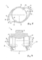
- Ein Ausführungsbeispiel der Erfindung ist In den Zeichnungen dargestellt und wird im Folgenden näher beschrieben. Es zeigen
- Fig. 1 bis 3
- drei perspektivische Ansichten des Laufrades,
- Fig. 4
- einen axialen Schnitt durch das Laufrad,
- Fig. 5
- einen Schnitt nach B-B in
Fig. 4 , - Fig. 6
- einen Schnitt nach A-A in
Fig. 5 . - Das Laufrad 1 einer Kreiselpumpe weist einen zylindrischen, topfförmigen Laufradkörper auf, dessen Achse koaxial mit der Laufradachse ist. Die zylindrische Topfaußenwand 2 des Laufradtopfes ist an einer Stirnseite 3 geschlossen und bildet dort einen vorstehenden Ansatz 4 zum Befestigen an der Welle eines nicht dargestellten Elektromotors. Die der Stirnseite 3 gegenüberliegende zweite Stirnseite 4 ist offen und bildet den Saugmund 5 des Laufrades.
- In der Innenwand des Saugmunds 5 sind Kanäle bzw. Nuten 6 eingebracht, wobei jede Nut schräg zur Laufradachse liegt und jeweils unterhalb einer Durchtrittsöffnung 7 angeordnet ist, die sich in der Topfaußenwand 2 befindet und die Verbindungsöffnung darstellt zu jeweils einem Austrittskanal 8, der an der Außenseite der Topfaußenwand 2 angeordnet ist. Durch die Nuten 6 bzw. die schrägen Zulaufkanäle 6 wird die geförderte Flüssigkeit zusammen mit den Feststoffen gezielt den Durchtrittsöffnungen 7 und den Austrittskanälen 8 zugeführt. Hierbei ist das untere Ende der Nut 6 weiter von der dazugehörigen Austrittsöffnung 12 entfernt ist als das obere Ende der Nut. Die bis zu zehn Nuten liegen im Anströmungsbereich zu der Durchtrittsöffnung des zufließenden Mediums in einer unterhalb der Durchtrittsöffnung angeordneten, horizontal kreisrunden oder zylindrischen Ebene.
- Jeder der beiden, einander diametral gegenüberliegenden Austrittskanäle 8 ist von einer Kanalaußenwand 9 und zwei Seitenwänden 10 gebildet, die an einer Austrittsöffnung 11 enden, durch die die geförderte Flüssigkeit austritt. Hierbei wird die sich nach außen spiralförmig erweiternde Kanalaußenwand von einer gekrümmten Fläche gebildet, deren gerade Erzeugenden parallel zur Laufradachse liegen und längs einer Kurve verlaufen, deren Radius nach außen hin zunimmt. Entsprechend dieser Außenwandform sind die Seitenwände 10 in ihrer Breite zunehmend gestaltet, wobei die Seitenwände über eine Krümmung in die Kanalaußenwand 9 übergehen. Hierbei ist auch von Bedeutung, dass bei senkrechter Laufradachse und unten angeordnetem Saugmund die untere Seitenwand 10 sowohl zur Austrittsöffnung 12 als auch radial nach außen hin ansteigt.
- Die obere Seitenwand des Austrittskanals kann sowohl zur Austrittsöffnung 12 hin abfallen als auch senkrecht zur Achse des Laufrades stehen.
- Jeder Austrittskanal 8 endet in einer Austrittsöffnung 12, deren Austrittsfläche tangential oder zumindest im Wesentlichen tangential zur Topfaußenwand angeordnet ist. Hierbei besitzt die Austrittsöffnung 12 die Form eines Trapezes mit zwei abgerundeten äußeren Ecken, wobei diese Trapezform dadurch zustande kommt, dass die Seitenwände 10 des Austrittskanals 8 derart schräg angeordnet sind, dass ihr Abstand A voneinander mit wachsender Entfernung von der zylindrischen Topfaußenwand abnimmt. Damit steigt in den in
Fig. 1 bis 3 dargestellten Abbildungen die untere Seitenwand 10 von innen nach außen hin an und die obere Seitenwand 10 fällt von innen nach außen gesehen ab. Hierbei ist auch von Bedeutung, dass bei senkrechter Laufradachse und unten angeordnetem Saugmund die untere Seitenwand 10 sowohl zur Austrittsöffnung 12 als auch radial nach außen hin ansteigt. - Die obere Seitenwand des Austrittskanals kann sowohl zur Austrittsöffnung 12 hin abfallen als auch senkrecht zur Achse des Laufrades stehen.
- Die Durchtrittsöffnung 7 besitzt eine der Austrittsöffnungen 12 nahe zur Laufradachse parallele Innenkante 13, die abgerundet ist und von der Topfaußenwand 2 gebildet wird. An dieser Innenkante 13 ist die Topfaußenwand 2 an ihrer Außenseite abnehmend gebildet, so dass der Außenrand 14 der Innenkante 13 abnehmend abgeschrägt ist, wodurch der Durchtritt des Mediums und der Feststoffe erleichtert wird.
- In einer alternativen Ausgestaltung fehlt die untere Seitenwand 10 und die Eingangsöffnung des Saugmundes befindet sich in Höhe des unteren Bereichs des Austrittskanals 8, so dass Kanal 8 und Eingangsöffnung ineinander übergehen. Sobald das Laufrad sich in der Pumpenkammer befindet, wird der untere Bereich des Kanals 8 durch die Pumpenkammer-Seitenwand abgedeckt.
Claims (15)
- Laufrad (1) einer Kreiselpumpe mit einer topfförmigen, zur Laufradachse koaxialen Außenwand (2), von der eine Stirnseite (3) geschlossen und die gegenüberliegende Stirnseite geöffnet ist und den Saugmund (5) bildet, dadurch gekennzeichnet, dass in der zylindrischen Außenwand (2) mindestens zwei Durchtrittsöffnungen (7) angeordnet sind, die jeweils von einem Austrittskanal (8) überdeckt sind, und dass der Austrittskanal (8) eine gekrümmte, sich nach außen insbesondere spiralförmig erweiternde flache Kanalaußenwand (9) aufweist, die zusammen mit sich in Ausströmrichtung erweiternden Seitenwänden (10) an ihrem Ende eine Austrittsöffnung (12) bildet.
- Laufrad nach Anspruch1, dadurch gekennzeichnet, dass die Austrittsöffnung (12) die Form eines Trapezes mit zwei abgerundeten äußeren Ecken aufweist.
- Laufrad nach Anspruch 1 oder 2, dadurch gekennzeichnet, dass die Innenkante (13) jeder Austrittsöffnung (12) innerhalb der zylindrischen Topfaußenwand (2) liegt.
- Laufrad nach Anspruch 3, dadurch gekennzeichnet, dass der Außenrand (14) der Innenkante (13) der Austrittsöffnung (12) zur Innenkante hin abnehmend abgeschrägt ist.
- Laufrad nach einem der vorherigen Ansprüche, dadurch gekennzeichnet, dass die zwei Seitenwände (10) des Austrittskanals (8) derart schräg angeordnet sind, dass ihr Abstand (A) voneinander mit wachsender Entfernung von der zylindrischen Topfaußenwand (2) abnimmt.
- Laufrad nach einem der vorherigen Ansprüche, dadurch gekennzeichnet, dass bei senkrechter Laufradachse und unten angeordnetem Saugmund die untere Seitenwand (10) sowohl zur Austrittsöffnung (12) als auch radial nach außen hin ansteigt.
- Laufrad nach einem der vorherigen Ansprüche, dadurch gekennzeichnet, dass die obere Seitenwand des Austrittskanals zur Austrittsöffnung hin abfällt.
- Laufrad nach einem der vorherigen Ansprüche, dadurch gekennzeichnet, dass die Austrittsöffnung (12) im Wesentlichen tangential zur Topfaußenwand (2) angeordnet ist.
- Laufrad nach einem der vorherigen Ansprüche, dadurch gekennzeichnet, dass die Innenwand des Saugmundes (5) mindestens eine zur Laufradachse schräge Nut (6) aufweist, um eine Verwirbelung der eingehenden Strömung zu erreichen.
- Laufrad nach Anspruch 9, dadurch gekennzeichnet, dass die Nut (6) unterhalb der Durchtrittsöffnung (7) angeordnet ist.
- Laufrad nach Anspruch 9 oer 10, dadurch gekennzeichnet, dass das untere Ende der Nut (6) weiter von der dazugehörigen Austrittsöffnung (12) entfernt ist als das obere Ende der Nut.
- Laufrad nach einem der vorherigen Ansprüche, dadurch gekennzeichnet, dass die Kanalaußenwand (9) eine gekrümmte Fläche ist mit einer geraden, zur Laufradachse parallelen Erzeugenden, die längs einer Kurve insbesondere einer spiralförmigen Kurve verläuft.
- Laufrad nach einem der vorherigen Ansprüche, dadurch gekennzeichnet, dass es zwei oder vier einander diametral gegenüberliegende Austrittskanäle aufweist.
- Laufrad nach einem der vorherigen Ansprüche, dadurch gekennzeichnet, dass zwei, drei oder vier Austrittskanäle (8) an der Außenseite des topfförmigen Laufradkörpers angeordnet sind.
- Verwendung eines Laufrades (1) nach einem der vorherigen Ansprüche zur Förderung von industriellen und/oder kommunalen ungereinigten Abwässern.
Applications Claiming Priority (1)
| Application Number | Priority Date | Filing Date | Title |
|---|---|---|---|
| DE102010026756A DE102010026756B4 (de) | 2010-07-09 | 2010-07-09 | Laufrad einer Kreiselpumpe |
Publications (3)
| Publication Number | Publication Date |
|---|---|
| EP2405143A2 true EP2405143A2 (de) | 2012-01-11 |
| EP2405143A3 EP2405143A3 (de) | 2015-01-14 |
| EP2405143B1 EP2405143B1 (de) | 2019-08-28 |
Family
ID=44343689
Family Applications (1)
| Application Number | Title | Priority Date | Filing Date |
|---|---|---|---|
| EP11005625.6A Active EP2405143B1 (de) | 2010-07-09 | 2011-07-08 | Laufrad einer Kreiselpumpe |
Country Status (2)
| Country | Link |
|---|---|
| EP (1) | EP2405143B1 (de) |
| DE (1) | DE102010026756B4 (de) |
Family Cites Families (7)
| Publication number | Priority date | Publication date | Assignee | Title |
|---|---|---|---|---|
| FR742839A (de) * | 1933-03-17 | |||
| CH94909A (de) * | 1921-05-21 | 1922-06-01 | Peter Alfred | Kanallose Kreiselpumpe, insbesondere zum Fördern von unreinen Flüssigkeiten mit verschiedenen spezifischen Gewichten. |
| US2432247A (en) * | 1944-11-03 | 1947-12-09 | Lee V Mcanallen | Pump |
| US3134331A (en) * | 1963-04-19 | 1964-05-26 | George T Adams | Reversible self-priming pump |
| DE2844990C2 (de) * | 1978-10-16 | 1984-01-26 | Wojewódzkie Przedsiębiorstwo Gospodarki Komunalnej i Mieszkaniowej, Piła | Kreiselpumpe |
| DE3615686A1 (de) * | 1986-05-09 | 1987-11-12 | Klein Schanzlin & Becker Ag | Kanalrad fuer kreiselpumpen |
| BRPI0802897A2 (pt) * | 2008-08-19 | 2011-04-26 | Higra Ind Ltda | bombas modulares |
-
2010
- 2010-07-09 DE DE102010026756A patent/DE102010026756B4/de not_active Revoked
-
2011
- 2011-07-08 EP EP11005625.6A patent/EP2405143B1/de active Active
Also Published As
| Publication number | Publication date |
|---|---|
| DE102010026756B4 (de) | 2012-10-25 |
| EP2405143B1 (de) | 2019-08-28 |
| EP2405143A3 (de) | 2015-01-14 |
| DE102010026756A1 (de) | 2012-01-12 |
Similar Documents
| Publication | Publication Date | Title |
|---|---|---|
| EP2495444B1 (de) | Pumpe | |
| DE69332086T2 (de) | Pumpenlaufrad und kreiselpumpe für zähflussige medien mit diesem laufrad | |
| EP2188532B1 (de) | Pumpenlaufrad und pumpe umfassend ein derartiges pumpenlaufrad | |
| EP3317544B1 (de) | Freistrompumpe | |
| DE102014106440A1 (de) | Laufrad, insbesondere für eine Seitenkanalmaschine | |
| EP3779201B1 (de) | Abstreifelement für laufradeintrittskanten von abwasserpumpen | |
| DE102012216196A1 (de) | Pumpe | |
| DE102005031420A1 (de) | Kombinierte Tauch-/Flachabsaug-Rotationspumpe | |
| EP2932105B1 (de) | Pumpvorrichtung mit einem strömungsleitelement | |
| WO2012069619A1 (de) | Selbstreinigende deckplatte in einer pumpe mit radialer strömung | |
| EP2405143B1 (de) | Laufrad einer Kreiselpumpe | |
| EP2138723B1 (de) | Kreiselpumpe mit Freistromlaufrad | |
| EP3303845B1 (de) | Selbstansaugende pumpenaggregation | |
| DE4239071C2 (de) | Tauchpumpenaggregat | |
| EP1131560B1 (de) | Seitenkanalpumpe | |
| EP1583910B1 (de) | Freistrompumpe | |
| DE19711970A1 (de) | Vorrichtung zum Regulieren der Fördermenge einer vertikalachsigen Kreiselpumpe | |
| DE1528651A1 (de) | Schmutzwasserpumpe | |
| DE102010004379A1 (de) | Kraftstoffpumpe | |
| DE29906811U1 (de) | Mehrstufige Kreiselpumpe | |
| WO2014086473A1 (de) | Kreiselpumpe insbesondere für abwasser oder schmutzwasser | |
| EP1423613B1 (de) | Förderpumpe | |
| DE102012222336B4 (de) | Strömungsmaschine | |
| DE102013218410B4 (de) | Zentrifugalpumpe | |
| EP2754344B1 (de) | Strömungsmaschine für Flüssigkeiten |
Legal Events
| Date | Code | Title | Description |
|---|---|---|---|
| AK | Designated contracting states |
Kind code of ref document: A2 Designated state(s): AL AT BE BG CH CY CZ DE DK EE ES FI FR GB GR HR HU IE IS IT LI LT LU LV MC MK MT NL NO PL PT RO RS SE SI SK SM TR |
|
| AX | Request for extension of the european patent |
Extension state: BA ME |
|
| PUAI | Public reference made under article 153(3) epc to a published international application that has entered the european phase |
Free format text: ORIGINAL CODE: 0009012 |
|
| PUAL | Search report despatched |
Free format text: ORIGINAL CODE: 0009013 |
|
| AK | Designated contracting states |
Kind code of ref document: A3 Designated state(s): AL AT BE BG CH CY CZ DE DK EE ES FI FR GB GR HR HU IE IS IT LI LT LU LV MC MK MT NL NO PL PT RO RS SE SI SK SM TR |
|
| AX | Request for extension of the european patent |
Extension state: BA ME |
|
| RIC1 | Information provided on ipc code assigned before grant |
Ipc: F04D 29/22 20060101AFI20141205BHEP |
|
| 17P | Request for examination filed |
Effective date: 20150529 |
|
| RBV | Designated contracting states (corrected) |
Designated state(s): AL AT BE BG CH CY CZ DE DK EE ES FI FR GB GR HR HU IE IS IT LI LT LU LV MC MK MT NL NO PL PT RO RS SE SI SK SM TR |
|
| STAA | Information on the status of an ep patent application or granted ep patent |
Free format text: STATUS: EXAMINATION IS IN PROGRESS |
|
| 17Q | First examination report despatched |
Effective date: 20181010 |
|
| GRAP | Despatch of communication of intention to grant a patent |
Free format text: ORIGINAL CODE: EPIDOSNIGR1 |
|
| STAA | Information on the status of an ep patent application or granted ep patent |
Free format text: STATUS: GRANT OF PATENT IS INTENDED |
|
| INTG | Intention to grant announced |
Effective date: 20190408 |
|
| GRAS | Grant fee paid |
Free format text: ORIGINAL CODE: EPIDOSNIGR3 |
|
| GRAA | (expected) grant |
Free format text: ORIGINAL CODE: 0009210 |
|
| STAA | Information on the status of an ep patent application or granted ep patent |
Free format text: STATUS: THE PATENT HAS BEEN GRANTED |
|
| AK | Designated contracting states |
Kind code of ref document: B1 Designated state(s): AL AT BE BG CH CY CZ DE DK EE ES FI FR GB GR HR HU IE IS IT LI LT LU LV MC MK MT NL NO PL PT RO RS SE SI SK SM TR |
|
| REG | Reference to a national code |
Ref country code: GB Ref legal event code: FG4D Free format text: NOT ENGLISH |
|
| REG | Reference to a national code |
Ref country code: CH Ref legal event code: EP |
|
| REG | Reference to a national code |
Ref country code: AT Ref legal event code: REF Ref document number: 1172750 Country of ref document: AT Kind code of ref document: T Effective date: 20190915 |
|
| REG | Reference to a national code |
Ref country code: IE Ref legal event code: FG4D Free format text: LANGUAGE OF EP DOCUMENT: GERMAN |
|
| REG | Reference to a national code |
Ref country code: DE Ref legal event code: R096 Ref document number: 502011016036 Country of ref document: DE |
|
| REG | Reference to a national code |
Ref country code: CH Ref legal event code: PK Free format text: BERICHTIGUNGEN |
|
| REG | Reference to a national code |
Ref country code: DE Ref legal event code: R083 Ref document number: 502011016036 Country of ref document: DE |
|
| RIN2 | Information on inventor provided after grant (corrected) |
Inventor name: STARK, HOLGER Inventor name: STROESSNER, WOLFGANG Inventor name: GEIER, WOLFGANG Inventor name: OTTO, ALFRED, J. |
|
| REG | Reference to a national code |
Ref country code: NL Ref legal event code: MP Effective date: 20190828 |
|
| REG | Reference to a national code |
Ref country code: LT Ref legal event code: MG4D |
|
| PG25 | Lapsed in a contracting state [announced via postgrant information from national office to epo] |
Ref country code: PT Free format text: LAPSE BECAUSE OF FAILURE TO SUBMIT A TRANSLATION OF THE DESCRIPTION OR TO PAY THE FEE WITHIN THE PRESCRIBED TIME-LIMIT Effective date: 20191230 Ref country code: FI Free format text: LAPSE BECAUSE OF FAILURE TO SUBMIT A TRANSLATION OF THE DESCRIPTION OR TO PAY THE FEE WITHIN THE PRESCRIBED TIME-LIMIT Effective date: 20190828 Ref country code: LT Free format text: LAPSE BECAUSE OF FAILURE TO SUBMIT A TRANSLATION OF THE DESCRIPTION OR TO PAY THE FEE WITHIN THE PRESCRIBED TIME-LIMIT Effective date: 20190828 Ref country code: NL Free format text: LAPSE BECAUSE OF FAILURE TO SUBMIT A TRANSLATION OF THE DESCRIPTION OR TO PAY THE FEE WITHIN THE PRESCRIBED TIME-LIMIT Effective date: 20190828 Ref country code: BG Free format text: LAPSE BECAUSE OF FAILURE TO SUBMIT A TRANSLATION OF THE DESCRIPTION OR TO PAY THE FEE WITHIN THE PRESCRIBED TIME-LIMIT Effective date: 20191128 Ref country code: NO Free format text: LAPSE BECAUSE OF FAILURE TO SUBMIT A TRANSLATION OF THE DESCRIPTION OR TO PAY THE FEE WITHIN THE PRESCRIBED TIME-LIMIT Effective date: 20191128 Ref country code: SE Free format text: LAPSE BECAUSE OF FAILURE TO SUBMIT A TRANSLATION OF THE DESCRIPTION OR TO PAY THE FEE WITHIN THE PRESCRIBED TIME-LIMIT Effective date: 20190828 Ref country code: HR Free format text: LAPSE BECAUSE OF FAILURE TO SUBMIT A TRANSLATION OF THE DESCRIPTION OR TO PAY THE FEE WITHIN THE PRESCRIBED TIME-LIMIT Effective date: 20190828 |
|
| PG25 | Lapsed in a contracting state [announced via postgrant information from national office to epo] |
Ref country code: IS Free format text: LAPSE BECAUSE OF FAILURE TO SUBMIT A TRANSLATION OF THE DESCRIPTION OR TO PAY THE FEE WITHIN THE PRESCRIBED TIME-LIMIT Effective date: 20191228 Ref country code: RS Free format text: LAPSE BECAUSE OF FAILURE TO SUBMIT A TRANSLATION OF THE DESCRIPTION OR TO PAY THE FEE WITHIN THE PRESCRIBED TIME-LIMIT Effective date: 20190828 Ref country code: GR Free format text: LAPSE BECAUSE OF FAILURE TO SUBMIT A TRANSLATION OF THE DESCRIPTION OR TO PAY THE FEE WITHIN THE PRESCRIBED TIME-LIMIT Effective date: 20191129 Ref country code: AL Free format text: LAPSE BECAUSE OF FAILURE TO SUBMIT A TRANSLATION OF THE DESCRIPTION OR TO PAY THE FEE WITHIN THE PRESCRIBED TIME-LIMIT Effective date: 20190828 Ref country code: LV Free format text: LAPSE BECAUSE OF FAILURE TO SUBMIT A TRANSLATION OF THE DESCRIPTION OR TO PAY THE FEE WITHIN THE PRESCRIBED TIME-LIMIT Effective date: 20190828 Ref country code: ES Free format text: LAPSE BECAUSE OF FAILURE TO SUBMIT A TRANSLATION OF THE DESCRIPTION OR TO PAY THE FEE WITHIN THE PRESCRIBED TIME-LIMIT Effective date: 20190828 |
|
| PG25 | Lapsed in a contracting state [announced via postgrant information from national office to epo] |
Ref country code: TR Free format text: LAPSE BECAUSE OF FAILURE TO SUBMIT A TRANSLATION OF THE DESCRIPTION OR TO PAY THE FEE WITHIN THE PRESCRIBED TIME-LIMIT Effective date: 20190828 |
|
| PG25 | Lapsed in a contracting state [announced via postgrant information from national office to epo] |
Ref country code: PL Free format text: LAPSE BECAUSE OF FAILURE TO SUBMIT A TRANSLATION OF THE DESCRIPTION OR TO PAY THE FEE WITHIN THE PRESCRIBED TIME-LIMIT Effective date: 20190828 Ref country code: DK Free format text: LAPSE BECAUSE OF FAILURE TO SUBMIT A TRANSLATION OF THE DESCRIPTION OR TO PAY THE FEE WITHIN THE PRESCRIBED TIME-LIMIT Effective date: 20190828 Ref country code: EE Free format text: LAPSE BECAUSE OF FAILURE TO SUBMIT A TRANSLATION OF THE DESCRIPTION OR TO PAY THE FEE WITHIN THE PRESCRIBED TIME-LIMIT Effective date: 20190828 Ref country code: RO Free format text: LAPSE BECAUSE OF FAILURE TO SUBMIT A TRANSLATION OF THE DESCRIPTION OR TO PAY THE FEE WITHIN THE PRESCRIBED TIME-LIMIT Effective date: 20190828 |
|
| PG25 | Lapsed in a contracting state [announced via postgrant information from national office to epo] |
Ref country code: SM Free format text: LAPSE BECAUSE OF FAILURE TO SUBMIT A TRANSLATION OF THE DESCRIPTION OR TO PAY THE FEE WITHIN THE PRESCRIBED TIME-LIMIT Effective date: 20190828 Ref country code: SK Free format text: LAPSE BECAUSE OF FAILURE TO SUBMIT A TRANSLATION OF THE DESCRIPTION OR TO PAY THE FEE WITHIN THE PRESCRIBED TIME-LIMIT Effective date: 20190828 Ref country code: CZ Free format text: LAPSE BECAUSE OF FAILURE TO SUBMIT A TRANSLATION OF THE DESCRIPTION OR TO PAY THE FEE WITHIN THE PRESCRIBED TIME-LIMIT Effective date: 20190828 Ref country code: IS Free format text: LAPSE BECAUSE OF FAILURE TO SUBMIT A TRANSLATION OF THE DESCRIPTION OR TO PAY THE FEE WITHIN THE PRESCRIBED TIME-LIMIT Effective date: 20200224 |
|
| REG | Reference to a national code |
Ref country code: DE Ref legal event code: R097 Ref document number: 502011016036 Country of ref document: DE |
|
| PLBE | No opposition filed within time limit |
Free format text: ORIGINAL CODE: 0009261 |
|
| STAA | Information on the status of an ep patent application or granted ep patent |
Free format text: STATUS: NO OPPOSITION FILED WITHIN TIME LIMIT |
|
| PG2D | Information on lapse in contracting state deleted |
Ref country code: IS |
|
| 26N | No opposition filed |
Effective date: 20200603 |
|
| PG25 | Lapsed in a contracting state [announced via postgrant information from national office to epo] |
Ref country code: SI Free format text: LAPSE BECAUSE OF FAILURE TO SUBMIT A TRANSLATION OF THE DESCRIPTION OR TO PAY THE FEE WITHIN THE PRESCRIBED TIME-LIMIT Effective date: 20190828 |
|
| PG25 | Lapsed in a contracting state [announced via postgrant information from national office to epo] |
Ref country code: MC Free format text: LAPSE BECAUSE OF FAILURE TO SUBMIT A TRANSLATION OF THE DESCRIPTION OR TO PAY THE FEE WITHIN THE PRESCRIBED TIME-LIMIT Effective date: 20190828 |
|
| REG | Reference to a national code |
Ref country code: CH Ref legal event code: PL |
|
| REG | Reference to a national code |
Ref country code: BE Ref legal event code: MM Effective date: 20200731 |
|
| PG25 | Lapsed in a contracting state [announced via postgrant information from national office to epo] |
Ref country code: LI Free format text: LAPSE BECAUSE OF NON-PAYMENT OF DUE FEES Effective date: 20200731 Ref country code: CH Free format text: LAPSE BECAUSE OF NON-PAYMENT OF DUE FEES Effective date: 20200731 Ref country code: LU Free format text: LAPSE BECAUSE OF NON-PAYMENT OF DUE FEES Effective date: 20200708 |
|
| PG25 | Lapsed in a contracting state [announced via postgrant information from national office to epo] |
Ref country code: BE Free format text: LAPSE BECAUSE OF NON-PAYMENT OF DUE FEES Effective date: 20200731 |
|
| PG25 | Lapsed in a contracting state [announced via postgrant information from national office to epo] |
Ref country code: IE Free format text: LAPSE BECAUSE OF NON-PAYMENT OF DUE FEES Effective date: 20200708 |
|
| REG | Reference to a national code |
Ref country code: AT Ref legal event code: MM01 Ref document number: 1172750 Country of ref document: AT Kind code of ref document: T Effective date: 20200708 |
|
| PG25 | Lapsed in a contracting state [announced via postgrant information from national office to epo] |
Ref country code: AT Free format text: LAPSE BECAUSE OF NON-PAYMENT OF DUE FEES Effective date: 20200708 |
|
| PG25 | Lapsed in a contracting state [announced via postgrant information from national office to epo] |
Ref country code: MT Free format text: LAPSE BECAUSE OF FAILURE TO SUBMIT A TRANSLATION OF THE DESCRIPTION OR TO PAY THE FEE WITHIN THE PRESCRIBED TIME-LIMIT Effective date: 20190828 Ref country code: CY Free format text: LAPSE BECAUSE OF FAILURE TO SUBMIT A TRANSLATION OF THE DESCRIPTION OR TO PAY THE FEE WITHIN THE PRESCRIBED TIME-LIMIT Effective date: 20190828 |
|
| PG25 | Lapsed in a contracting state [announced via postgrant information from national office to epo] |
Ref country code: MK Free format text: LAPSE BECAUSE OF FAILURE TO SUBMIT A TRANSLATION OF THE DESCRIPTION OR TO PAY THE FEE WITHIN THE PRESCRIBED TIME-LIMIT Effective date: 20190828 |
|
| P01 | Opt-out of the competence of the unified patent court (upc) registered |
Effective date: 20230615 |
|
| PGFP | Annual fee paid to national office [announced via postgrant information from national office to epo] |
Ref country code: GB Payment date: 20250619 Year of fee payment: 15 |
|
| PGFP | Annual fee paid to national office [announced via postgrant information from national office to epo] |
Ref country code: FR Payment date: 20250620 Year of fee payment: 15 |
|
| PGFP | Annual fee paid to national office [announced via postgrant information from national office to epo] |
Ref country code: DE Payment date: 20250620 Year of fee payment: 15 |
|
| PGFP | Annual fee paid to national office [announced via postgrant information from national office to epo] |
Ref country code: IT Payment date: 20250619 Year of fee payment: 15 |