EP2405115B1 - Ventilanordnung mit getrenntem Durchfluss - Google Patents
Ventilanordnung mit getrenntem Durchfluss Download PDFInfo
- Publication number
- EP2405115B1 EP2405115B1 EP20110169228 EP11169228A EP2405115B1 EP 2405115 B1 EP2405115 B1 EP 2405115B1 EP 20110169228 EP20110169228 EP 20110169228 EP 11169228 A EP11169228 A EP 11169228A EP 2405115 B1 EP2405115 B1 EP 2405115B1
- Authority
- EP
- European Patent Office
- Prior art keywords
- valve
- inlet
- outlet
- flow
- fuel
- Prior art date
- Legal status (The legal status is an assumption and is not a legal conclusion. Google has not performed a legal analysis and makes no representation as to the accuracy of the status listed.)
- Not-in-force
Links
- 239000000446 fuel Substances 0.000 claims description 56
- 239000012530 fluid Substances 0.000 claims description 6
- 238000007789 sealing Methods 0.000 description 6
- 238000002485 combustion reaction Methods 0.000 description 3
- 230000008878 coupling Effects 0.000 description 3
- 238000010168 coupling process Methods 0.000 description 3
- 238000005859 coupling reaction Methods 0.000 description 3
- 230000012447 hatching Effects 0.000 description 3
- 238000004939 coking Methods 0.000 description 2
- 230000009286 beneficial effect Effects 0.000 description 1
- 230000000903 blocking effect Effects 0.000 description 1
- 230000015556 catabolic process Effects 0.000 description 1
- 239000000571 coke Substances 0.000 description 1
- 238000006731 degradation reaction Methods 0.000 description 1
- 230000000593 degrading effect Effects 0.000 description 1
- 230000001419 dependent effect Effects 0.000 description 1
- 238000002347 injection Methods 0.000 description 1
- 239000007924 injection Substances 0.000 description 1
- 238000004519 manufacturing process Methods 0.000 description 1
- 230000007246 mechanism Effects 0.000 description 1
- 230000001141 propulsive effect Effects 0.000 description 1
- 230000003068 static effect Effects 0.000 description 1
Images


Classifications
-
- F—MECHANICAL ENGINEERING; LIGHTING; HEATING; WEAPONS; BLASTING
- F02—COMBUSTION ENGINES; HOT-GAS OR COMBUSTION-PRODUCT ENGINE PLANTS
- F02C—GAS-TURBINE PLANTS; AIR INTAKES FOR JET-PROPULSION PLANTS; CONTROLLING FUEL SUPPLY IN AIR-BREATHING JET-PROPULSION PLANTS
- F02C7/00—Features, components parts, details or accessories, not provided for in, or of interest apart form groups F02C1/00 - F02C6/00; Air intakes for jet-propulsion plants
- F02C7/22—Fuel supply systems
- F02C7/228—Dividing fuel between various burners
-
- F—MECHANICAL ENGINEERING; LIGHTING; HEATING; WEAPONS; BLASTING
- F02—COMBUSTION ENGINES; HOT-GAS OR COMBUSTION-PRODUCT ENGINE PLANTS
- F02C—GAS-TURBINE PLANTS; AIR INTAKES FOR JET-PROPULSION PLANTS; CONTROLLING FUEL SUPPLY IN AIR-BREATHING JET-PROPULSION PLANTS
- F02C7/00—Features, components parts, details or accessories, not provided for in, or of interest apart form groups F02C1/00 - F02C6/00; Air intakes for jet-propulsion plants
- F02C7/22—Fuel supply systems
- F02C7/232—Fuel valves; Draining valves or systems
-
- H—ELECTRICITY
- H03—ELECTRONIC CIRCUITRY
- H03B—GENERATION OF OSCILLATIONS, DIRECTLY OR BY FREQUENCY-CHANGING, BY CIRCUITS EMPLOYING ACTIVE ELEMENTS WHICH OPERATE IN A NON-SWITCHING MANNER; GENERATION OF NOISE BY SUCH CIRCUITS
- H03B5/00—Generation of oscillations using amplifier with regenerative feedback from output to input
- H03B5/20—Generation of oscillations using amplifier with regenerative feedback from output to input with frequency-determining element comprising resistance and either capacitance or inductance, e.g. phase-shift oscillator
- H03B5/26—Generation of oscillations using amplifier with regenerative feedback from output to input with frequency-determining element comprising resistance and either capacitance or inductance, e.g. phase-shift oscillator frequency-determining element being part of bridge circuit in closed ring around which signal is transmitted; frequency-determining element being connected via a bridge circuit to such a closed ring, e.g. Wien-Bridge oscillator, parallel-T oscillator
- H03B5/28—Generation of oscillations using amplifier with regenerative feedback from output to input with frequency-determining element comprising resistance and either capacitance or inductance, e.g. phase-shift oscillator frequency-determining element being part of bridge circuit in closed ring around which signal is transmitted; frequency-determining element being connected via a bridge circuit to such a closed ring, e.g. Wien-Bridge oscillator, parallel-T oscillator active element in amplifier being vacuum tube
-
- H—ELECTRICITY
- H03—ELECTRONIC CIRCUITRY
- H03H—IMPEDANCE NETWORKS, e.g. RESONANT CIRCUITS; RESONATORS
- H03H11/00—Networks using active elements
- H03H11/02—Multiple-port networks
- H03H11/16—Networks for phase shifting
- H03H11/18—Two-port phase shifters providing a predetermined phase shift, e.g. "all-pass" filters
-
- F—MECHANICAL ENGINEERING; LIGHTING; HEATING; WEAPONS; BLASTING
- F05—INDEXING SCHEMES RELATING TO ENGINES OR PUMPS IN VARIOUS SUBCLASSES OF CLASSES F01-F04
- F05D—INDEXING SCHEME FOR ASPECTS RELATING TO NON-POSITIVE-DISPLACEMENT MACHINES OR ENGINES, GAS-TURBINES OR JET-PROPULSION PLANTS
- F05D2270/00—Control
- F05D2270/30—Control parameters, e.g. input parameters
- F05D2270/31—Fuel schedule for stage combustors
-
- Y—GENERAL TAGGING OF NEW TECHNOLOGICAL DEVELOPMENTS; GENERAL TAGGING OF CROSS-SECTIONAL TECHNOLOGIES SPANNING OVER SEVERAL SECTIONS OF THE IPC; TECHNICAL SUBJECTS COVERED BY FORMER USPC CROSS-REFERENCE ART COLLECTIONS [XRACs] AND DIGESTS
- Y10—TECHNICAL SUBJECTS COVERED BY FORMER USPC
- Y10T—TECHNICAL SUBJECTS COVERED BY FORMER US CLASSIFICATION
- Y10T137/00—Fluid handling
- Y10T137/8593—Systems
- Y10T137/87096—Valves with separate, correlated, actuators
- Y10T137/87113—Interlocked
-
- Y—GENERAL TAGGING OF NEW TECHNOLOGICAL DEVELOPMENTS; GENERAL TAGGING OF CROSS-SECTIONAL TECHNOLOGIES SPANNING OVER SEVERAL SECTIONS OF THE IPC; TECHNICAL SUBJECTS COVERED BY FORMER USPC CROSS-REFERENCE ART COLLECTIONS [XRACs] AND DIGESTS
- Y10—TECHNICAL SUBJECTS COVERED BY FORMER USPC
- Y10T—TECHNICAL SUBJECTS COVERED BY FORMER US CLASSIFICATION
- Y10T137/00—Fluid handling
- Y10T137/8593—Systems
- Y10T137/87096—Valves with separate, correlated, actuators
- Y10T137/87121—Coaxial stems
- Y10T137/87129—Rotary
-
- Y—GENERAL TAGGING OF NEW TECHNOLOGICAL DEVELOPMENTS; GENERAL TAGGING OF CROSS-SECTIONAL TECHNOLOGIES SPANNING OVER SEVERAL SECTIONS OF THE IPC; TECHNICAL SUBJECTS COVERED BY FORMER USPC CROSS-REFERENCE ART COLLECTIONS [XRACs] AND DIGESTS
- Y10—TECHNICAL SUBJECTS COVERED BY FORMER USPC
- Y10T—TECHNICAL SUBJECTS COVERED BY FORMER US CLASSIFICATION
- Y10T137/00—Fluid handling
- Y10T137/8593—Systems
- Y10T137/87249—Multiple inlet with multiple outlet
-
- Y—GENERAL TAGGING OF NEW TECHNOLOGICAL DEVELOPMENTS; GENERAL TAGGING OF CROSS-SECTIONAL TECHNOLOGIES SPANNING OVER SEVERAL SECTIONS OF THE IPC; TECHNICAL SUBJECTS COVERED BY FORMER USPC CROSS-REFERENCE ART COLLECTIONS [XRACs] AND DIGESTS
- Y10—TECHNICAL SUBJECTS COVERED BY FORMER USPC
- Y10T—TECHNICAL SUBJECTS COVERED BY FORMER US CLASSIFICATION
- Y10T137/00—Fluid handling
- Y10T137/8593—Systems
- Y10T137/87917—Flow path with serial valves and/or closures
- Y10T137/87981—Common actuator
Definitions
- the present invention relates to a split flow valve arrangement and finds particular utility for delivering fuel to an injector, for example in a gas turbine engine operating lean burn combustion.
- US 6,955,040 discloses a prior art split flow valve arrangement for a gas turbine engine operating lean burn combustion.
- the arrangement comprises a pair of linear hydraulic valves, one of which feeds fuel to the main injector nozzle and the other feeds fuel to the pilot injector nozzle.
- a signal fluid is provided to the first hydraulic valve to set the position of the piston to open or restrict main and pilot outlet ports.
- Fuel is supplied from a fuel manifold into main and pilot inlet ports in the first hydraulic valve.
- the pilot outlet port is connected to an inlet port on the second hydraulic valve.
- the second hydraulic valve also has an outlet port and is additionally supplied from the fuel manifold.
- the pistons in the first and second hydraulic valves are moved to allow no flow, main fuel flow plus pilot fuel flow, main fuel flow plus restricted pilot fuel flow (only supplied from the fuel manifold not from the first to the second hydraulic valve), or pilot flow only.
- the signal fluid is also fuel.
- valves are not tightly sealed so that fuel may leak through the ports which may result in fuel carbonation, particularly on engine shut down. This may restrict or even prevent the correct action of the hydraulic valves in subsequent engine operations, thereby compromising the injector performance.
- WO2009/150013 discloses a multi-function valve of a fuel system of a gas turbine engine.
- the valve comprises a first and second valve portions that move in synchronicity.
- the present invention provides a split flow valve arrangement that seeks to address the aforementioned problems.
- the present invention provides a split flow valve arrangement comprising a first valve portion having an inlet, a first outlet and a second outlet; the inlet selectively coupled to none, one or both of the first and second outlets; and a second valve portion having a first inlet coupled to the first outlet, a second inlet coupled to the second outlet, a main outlet and a secondary outlet; the first inlet is selectively coupled to the main outlet and the second inlet is selectively coupled to the secondary outlet; wherein the first and second valve portions are constrained to move in synchronicity to selectively direct fluid to flow from the inlet to none, one or both of the main and secondary outlets.
- This arrangement advantageously is more accurate and has better sealing than prior art valve arrangements.
- the first and second valve portions may rotate.
- the first valve portion may comprise a ball valve.
- This portion provides good sealing.
- the second valve portion may comprise a spool valve or a platen valve.
- this portion provides improved accuracy.
- the first and second valve portions may be driven by a common drive shaft.
- the common drive shaft may be controlled by a worm and wheel arrangement. This may provide a high torque output to give accurate rotational control.
- the first and second outlets may be filtered to prevent debris from compromising latter parts of the valve arrangement and the performance of downstream injection nozzles.
- the present invention also provides a fuel injector comprising a split flow valve arrangement; a gas turbine engine comprising a split flow valve arrangement as described; and a gas turbine engine comprising a fuel injector as described.
- the split flow valve arrangement may include any of the optional features disclosed above.
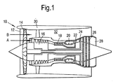
- a gas turbine engine 10 is shown in Figure 1 and comprises an air intake 12 and a propulsive fan 14 that generates two airflows A and B.
- the gas turbine engine 10 comprises, in axial flow A, an intermediate pressure compressor 16, a high pressure compressor 18, a combustor 20, a high pressure turbine 22, an intermediate pressure turbine 24, a low pressure turbine 26 and an exhaust nozzle 28.
- a nacelle 30 surrounds the gas turbine engine 10 and defines, in axial flow B, a bypass duct 32.
- the combustor 20 comprises a combustion chamber and a plurality of injectors or burners receiving a main and a pilot fuel flow to supply a main and a pilot injector nozzle.
- FIG. 2 An exemplary embodiment of the split flow valve arrangement 34 of the present invention is shown in Figure 2 .
- the arrangement 34 is coupled to a head of a burner unit 36 as will be described in more detail below.
- the arrangement 34 comprises a first valve portion 38 and a second valve portion 40.
- the first and second valve portions 38, 40 are coupled together and constrained to move in synchronicity with a common drive shaft 42 that is mounted to rotate via bearings 44 in static structure 46.
- a worm and wheel arrangement 48 is provided on the common drive shaft 42 comprising a wheel 50 mounted on or integral with the common drive shaft 42.
- the wheel 50 has teeth that intermesh with the external thread of a worm 52 such that when the worm 52 is driven linearly in one direction it causes the wheel 50, and hence the common drive shaft 42, to rotate in a first direction, and when the worm 52 is driven linearly in the other direction the wheel 50 and common drive shaft 42 rotate in the other direction.
- the first valve portion 38 is located in housing 54 and comprises a ball valve 56 mounted to the common drive shaft 42.
- the ball valve 56 is seated in dynamic face seals 58 that effectively seal against fluid leakage whilst accommodating irregularities in the shape of the ball valve 56 caused by manufacturing tolerances or trapped debris.
- the ball valve 56 comprises an inlet 60 that receives fuel from a fuel source (not shown).
- the inlet 60 is an aperture in the surface of the ball valve 56, the upper face as illustrated, that is coupled to a small internal cavity 62. It is beneficial that the cavity 62 is small because this reduces the volume of stagnant fuel and the consequent potential for coking.
- the first valve portion 38 comprises a first outlet 64 and a second outlet 66 that are apertures in the housing 54.
- the first and second outlets 64, 66 may be substantially the same and are located diametrically opposite to each other. As illustrated, the first and second outlets 64, 66 are positioned on the left and right hand sides of the ball valve 56 and are selectively coupled to the internal cavity 62 as will be described with respect to Figures 3 to 5 .
- the first outlet 64 is coupled to passages 68.
- the passages 68 may comprise a filter 70 to trap debris flowing into the passages 68 from the ball valve 56.
- the second outlet 66 is similarly coupled to passages 72 which may comprise a filter 74 to trap debris flowing into the passages 72 from the ball valve 56.
- the second valve portion 40 comprises a spool valve 76 in a cylindrical sleeve 78.
- the spool valve 76 is coupled to the common drive shaft 42 to rotate in synchronicity therewith.
- the second valve portion 40 comprises a first inlet 80 that is an aperture in the cylindrical sleeve 78.
- the first inlet 80 is coupled by the passages 68 to the first outlet 64 of the first valve portion 38.
- the second valve portion 40 further comprises a second inlet 82 that is also an aperture in the cylindrical sleeve 78.
- the second inlet 82 is coupled by the passages 72 to the second outlet 66 of the first valve portion 38.
- the first and second inlets 80, 82 may be located diametrically opposite to each other to allow easy coupling to the passages 68, 72 and are displaced axially from one another.
- the second valve portion 40 comprises a main outlet 84 and a secondary outlet 86.
- the spool valve 76 comprises a first recess 88 that can be positioned, as will be described with respect to Figures 3 to 5 , to selectively couple the first inlet 80 to the main outlet 84.
- the spool valve 76 comprises a second recess 90 that can be positioned to selectively couple the second inlet 82 to the secondary outlet 86.
- the main outlet 84 is axially aligned but circumferentially displaced from the first inlet 80 whereas the secondary outlet is circumferentially aligned but axially displaced, by being an aperture in the flat end not the curved cylindrical surface of the cylindrical sleeve 78. It will be apparent to the skilled reader that other configurations are possible within the scope of the claimed invention.
- the main outlet 84 is coupled via further flow passages 92 to supply a main injector nozzle 94 in the head of the burner unit 36.
- the secondary outlet 86 is coupled via further flow passages 96 to supply a pilot injector nozzle 98 in the head of the burner unit 36.
- the spool valve 76 may comprise seals 100 to seal the main outlet 84 from the secondary outlet 86.
- Figure 3 is a section through the ball valve 56 as indicated at III in Figure 2 at three flow conditions.
- the cross hatching indicates sections of the first valve portion 38 that contain fuel at the illustrated flow condition.
- the inlet 60 is unrestricted and therefore the cavity 62 always contains fuel.
- the ball valve 56 includes a valve member 102 that defines the internal cavity 62 and has a first arm 104 and a second arm 106.
- the arms are hollow and extend from the cavity 62 towards the outer surface of the ball valve 56. Movement of the valve member 102 selectively couples the cavity 62 to none, one or both of the first and second outlets 64, 66 via the first and second arms 104, 106.
- the first and second arms 104, 106 are always coupled to the cavity 62 and thus are always filled with fuel.
- the first and second arms 104, 106 each extend away from the cavity 62 and form an obtuse angle between them.
- the diameter of the first arm 104 may be larger than the diameter of the second arm 106 to regulate the relative flow through each arm 104, 106.
- the valve member 102 is rotated such that the first arm 104 is coupled to the first outlet 64. This permits fuel to flow from the fuel source into the inlet 60, through the cavity 62 and the first arm 104 and into the passages 68 towards the second valve portion 40.
- the angular position of the valve member 102 is also such that the second arm 106 is coupled to the second outlet 66. This permits fuel to flow from the fuel source into the inlet 60, through the cavity 62 and the second arm 106 and into the passages 72 towards the second valve portion 40.
- valve member 102 In the second illustrated flow condition, middle drawing, the valve member 102 is rotated such that the first arm 104 is still coupled to the first outlet 64, permitting fuel to flow as in the first flow condition. However, the angular position of the valve member 102 is such that the second arm 106 is not coupled to the second outlet 66 so that no fuel is permitted to flow to the second outlet 66 or into the passages 72.
- valve member 102 is rotated further such that neither the first arm 104 nor the second arm 106 are coupled to the first and second outlets 64, 66 respectively. Thus no fuel is permitted to flow into the passages 68, 72.
- Figure 4 is a section through the spool valve 76 at the axial position of the second inlet 82, second recess 90 and secondary outlet 86, as indicated at IV in Figure 2 .
- the spool valve 76 comprises a valve member 108 that includes the second recess 90 and an internal passage that selectively couples the second recess 90 to the secondary outlet 86.
- the valve member 108 rotates within the cylindrical sleeve 78, which includes the second inlet 82.
- valve member 108 In the first flow condition the valve member 108 is rotated such that the second inlet 82 is coupled to the secondary outlet 86 via the second recess 90.
- the cross hatching indicates areas in which fuel is present for each flow condition so in this first flow condition fuel is permitted to flow through the further passages 96 to the pilot injector nozzle 98.
- valve member 108 In the second flow condition the valve member 108 is rotated clockwise from the first flow condition but such that the second inlet 82 is still coupled to the secondary outlet 86 via the second recess 90. Finally, in the third flow condition the valve member 108 is rotated further clockwise until the body of the valve member 108 blocks the second inlet 82 and the cylindrical sleeve 78 blocks fuel from flowing into the second recess 90 and from there out of the secondary outlet 86.
- valve member 108 of the spool valve 76 Since the valve member 108 of the spool valve 76 is constrained to rotate in synchronicity with the valve member 102 of the ball valve 56 via the common drive shaft 42, there is no fuel flowing through the passages 72 in the third flow condition.
- the dynamic face seals 58 of the first valve portion 38 prevent any fuel from flowing through the second outlet 66 into the passages 72.
- the position of the valve member 108 of the spool valve 76 provides additional, back up, sealing in case of failure of the face seals 58.
- Figure 5 is a section through the spool valve 76 at the axial height of the first inlet 80, first recess 88 and main outlet 84 as indicated in Figure 2 by V. As in Figures 3 and 4 , cross hatching indicates regions in which fuel is present for each of the three flow conditions.
- valve member 108 In the first flow condition the valve member 108 is arranged such that the first recess 88 is coupled to both the first inlet 80 and the main outlet 84.
- fuel is permitted to flow from the passages 68, through the first inlet 80 into the first recess 88 and then out through the main outlet 84 through the further passages 92 to the main injector nozzle 94.
- the circumferential angle between the passages 68 leading to the first inlet 80 and the further passages 92 leading from the main outlet 84 is preferably less than 90° so that the first recess 88 can have a small volume to reduce the amount of stagnant fuel.
- valve member 108 In the second flow condition the valve member 108 is rotated clockwise from the first flow condition until the body of the valve member 108 blocks the first inlet 80. Thus no fuel is permitted to flow into the first recess 88 and so no fuel flows through the main outlet 84 into the further passages 92.
- valve member 108 In the third flow condition the valve member 108 is rotated further clockwise so that, as in the second flow condition, the body of the valve member 108 blocks the first inlet 80 so that no fuel can flow into the first recess 88, through the main outlet 84 and into the further passages 92.
- valve member 108 of the second valve portion 40 Since the valve member 108 of the second valve portion 40 is rotationally coupled to the valve member 102 of the first valve portion 38, no fuel flows into the passages 72 from the ball valve 56 in the second or third flow conditions.
- the body of the valve member 108 blocking the first inlet 80 therefore provides additional sealing as a back up in case of failure of the dynamic face seals 58.
- the worm and wheel arrangement 48 allows the valve members 102, 108 to be driven clockwise or anticlockwise between adjacent flow conditions.
- the split flow valve arrangement 34 can be set to the third flow condition, with no flow to either the main or the pilot injector nozzles 94, 98, and then the valve members 102, 108 rotated to the second flow condition to allow pilot fuel flow. From there the split flow valve arrangement 34 can be further rotated to the first flow condition to allow main and pilot flow, or can be rotated back to the third flow condition to prevent more flow.
- the worm 52 of the worm and wheel arrangement 48 may have sufficient travel to allow the valve members 102, 108 to rotate between the first and third flow conditions also without passing through the second flow condition.
- the ball valve 56 and dynamic face seals 58 provide excellent sealing against leakage.
- the spool valve 76 comprises accurately machined inlet and outlet ports so it provides accuracy. Therefore the split flow valve arrangement 34 of the present invention provides a valve having simultaneously good sealing and accuracy.
- the valve members 102, 108 may be designed so that the opening and shutting of the inlets and outlets is phased. This beneficially reduces wear on the ball valve 56 by reducing the instantaneous change of pressure caused by coupling the main and secondary outlets 84, 86 to the inlet 60. This coupling could expose the ball valve 56 to the potentially lower pressure in the combustor 20 and the burner unit 36. However, by provision of the passages 68, 72 between the first and second valve portions 38, 40, the speed of the pressure change is reduced.
- a worm and wheel arrangement 48 has been described to drive the common drive shaft 42 and thence the valve arrangement 34, other drive mechanisms may be substituted with equal felicity.
- the second valve portion 40 has been described as a spool valve 76, a rotary platen valve or other rotary valve may be used instead.
- the ball valve 56 may comprise different inlet 60 and outlets 64, 66 configurations.
- the angular spacing between the first and second outlets 64, 66 may also be varied within the scope of the present invention.
Landscapes
- Engineering & Computer Science (AREA)
- Chemical & Material Sciences (AREA)
- Combustion & Propulsion (AREA)
- Mechanical Engineering (AREA)
- General Engineering & Computer Science (AREA)
- Multiple-Way Valves (AREA)
- Taps Or Cocks (AREA)
Claims (12)
- Ein Wegeventil (34) bestehend aus- einem ersten Ventilabschnitt (38) mit einem Einlass (60), einem ersten Auslass (64) und einem zweiten Auslass (66); wobei der Einlass (60) selektiv an keinen, einen oder beide des ersten und zweiten Auslasses (64, 66) angeschlossen ist; und- einem zweiten Ventilabschnitt (40) mit einem ersten Einlass (80), der an einen ersten Auslass (64) angeschlossen ist, einem zweiten Einlass (82), der an einen zweiten Auslass (66) angeschlossen ist, einem Haupauslass (84) und einem sekundären Auslass (86); wobei der erste Einlass (80) selektiv an den Hauptauslass (84) und der zweite Einlass (82) selektiv an den sekundären Auslass (86) angeschlossen ist;
wobei der erste und der zweite Ventilabschnitt (38, 40) so beschränkt sind, dass sie sich gleichzeitig bewegen, um Flüssigkeit selektiv so zu leiten, dass sie vom Einlass (60) zu keinem, einem oder beiden des Haupt- und sekundären Auslasses (84, 86) fließt. - Ein Wegeventil (34) entsprechend Anspruch 1, wobei der erste und der zweite Ventilabschnitt (38, 40) rotieren.
- Ein Wegeventil (34) entsprechend Anspruch 2, wobei der erste Ventilabschnitt (38) ein Kugelventil (56) umfasst.
- Ein Wegeventil (34) entsprechend Anspruch 2 oder 3, wobei der zweite Ventilabschnitt (40) ein Schieberventil (76) umfasst.
- Ein Wegeventil (34) entsprechend Anspruch 2 oder 3, wobei der zweite Ventilabschnitt (40) ein Tellerventil umfasst.
- Ein Wegeventil (34) entsprechend einem der Ansprüche 2 bis 5, wobei der erste und der zweite Ventilabschnitt (38, 40) von einer gemeinsamen Antriebswelle (42) angetrieben werden.
- Ein Wegeventil (34) entsprechend Anspruch 6, wobei die gemeinsame Antriebswelle (42) durch ein Schneckenrad (48) gesteuert wird.
- Ein Wegeventil (34) entsprechend einem der vorhergehenden Ansprüche, wobei der erste und der zweite Auslass (64, 66) gefiltert sind.
- Ein Wegeventil (34) entsprechend einem der vorhergehenden Ansprüche, wobei der erste Ventilabschnitt (38) durch dynamische Gleitringdichtungen (58) abgedichtet ist.
- Ein Einspritzventil bestehend aus einem Wegeventil (34) entsprechend einem dem vorhergehenden Ansprüche.
- Ein Gasturbinenmotor (10)mit einem Wegeventil (34) entsprechend einem dem vorhergehenden Ansprüche.
- Ein Gasturbinenmotor (10) mit einem Einspritzventil entsprechend Anspruch 10.
Applications Claiming Priority (1)
| Application Number | Priority Date | Filing Date | Title |
|---|---|---|---|
| GB201011554A GB201011554D0 (en) | 2010-07-09 | 2010-07-09 | Split flow valve arrangement |
Publications (3)
| Publication Number | Publication Date |
|---|---|
| EP2405115A2 EP2405115A2 (de) | 2012-01-11 |
| EP2405115A3 EP2405115A3 (de) | 2013-08-07 |
| EP2405115B1 true EP2405115B1 (de) | 2014-08-20 |
Family
ID=42712126
Family Applications (1)
| Application Number | Title | Priority Date | Filing Date |
|---|---|---|---|
| EP20110169228 Not-in-force EP2405115B1 (de) | 2010-07-09 | 2011-06-09 | Ventilanordnung mit getrenntem Durchfluss |
Country Status (3)
| Country | Link |
|---|---|
| US (1) | US8387660B2 (de) |
| EP (1) | EP2405115B1 (de) |
| GB (1) | GB201011554D0 (de) |
Families Citing this family (3)
| Publication number | Priority date | Publication date | Assignee | Title |
|---|---|---|---|---|
| US9371917B2 (en) * | 2013-04-30 | 2016-06-21 | General Electric Company | Fuel conditioning system |
| CN111688471A (zh) * | 2019-03-11 | 2020-09-22 | 舍弗勒技术股份两合公司 | 车辆用热管理模块及其工作方法 |
| US11680549B2 (en) * | 2019-10-04 | 2023-06-20 | Hamilton Sundstrand Corporation | Fluid injection systems for fluid line purging |
Family Cites Families (8)
| Publication number | Priority date | Publication date | Assignee | Title |
|---|---|---|---|---|
| GB2158570B (en) * | 1984-05-10 | 1988-11-30 | Ex Cell O Corp | Mechanically operated fuel control system |
| US4738276A (en) * | 1986-06-06 | 1988-04-19 | Adams Donald L | Modular differential pressure transmitter/manifold for a fluid conveying pipeline |
| US4977917A (en) * | 1986-06-06 | 1990-12-18 | Adams Don L | Modular differential pressure transmitter/manifold for a fluid conveying pipeline |
| US5117867A (en) * | 1986-06-06 | 1992-06-02 | Adams Don L | Manifold for a differential pressure transmitter |
| US4823843A (en) * | 1988-06-01 | 1989-04-25 | Aptec, Inc. | Valve apparatus |
| US5274996A (en) | 1991-10-11 | 1994-01-04 | Allied-Signal, Inc. | Closed loop fuel control system |
| US6955040B1 (en) | 2004-03-31 | 2005-10-18 | General Electric Company | Controlled pressure fuel nozzle injector |
| CN102057194B (zh) * | 2008-06-09 | 2014-06-04 | 西门子公司 | 燃气涡轮机的燃料系统的多路阀 |
-
2010
- 2010-07-09 GB GB201011554A patent/GB201011554D0/en not_active Ceased
-
2011
- 2011-06-09 US US13/156,817 patent/US8387660B2/en not_active Expired - Fee Related
- 2011-06-09 EP EP20110169228 patent/EP2405115B1/de not_active Not-in-force
Also Published As
| Publication number | Publication date |
|---|---|
| US8387660B2 (en) | 2013-03-05 |
| EP2405115A3 (de) | 2013-08-07 |
| GB201011554D0 (en) | 2010-08-25 |
| EP2405115A2 (de) | 2012-01-11 |
| US20120006433A1 (en) | 2012-01-12 |
Similar Documents
| Publication | Publication Date | Title |
|---|---|---|
| JP6378726B2 (ja) | 蒸発燃料導入装置 | |
| US9121349B2 (en) | Fuel system | |
| EP2034225B1 (de) | System mit mehreren Turboladern und Abgasströmungsventil dafür | |
| US7784450B2 (en) | Exhaust-gas recirculation device for an internal combustion engine | |
| EP2405115B1 (de) | Ventilanordnung mit getrenntem Durchfluss | |
| JP5269928B2 (ja) | 大型2サイクルディーゼルエンジンの燃料弁 | |
| US20110120431A1 (en) | Exhaust Gas Recirculation Valve Actuator | |
| CN110195670A (zh) | 特别是用于供应高压气体设有通气口的节流阀体或致动器 | |
| JP6213788B2 (ja) | 内燃機関用排気ガスシステム | |
| CN111750535B (zh) | 一种燃气分配装置及应用该装置的燃气热水器 | |
| US8122700B2 (en) | Premix nozzles and gas turbine engine systems involving such nozzles | |
| EP3348799B1 (de) | Multi-durchflussweg-durchflussregelventil | |
| JP2018520290A (ja) | 分流装置を用いた注入液体燃料ノズルおよび供給配管 | |
| CN103670716B (zh) | 最小压力切断阀 | |
| CN103781998A (zh) | 用于燃气发动机的阀系统 | |
| US11230979B2 (en) | Aircraft engine fuel system and method | |
| KR101026990B1 (ko) | 유량 조절형 터빈 | |
| NL1041770B1 (en) | Improved fuel injection devices. | |
| CN204627826U (zh) | 流体分配器 | |
| US20150096284A1 (en) | Egr valve with ring seal for zero flow | |
| CN106286055B (zh) | 流体分配器 | |
| KR101026989B1 (ko) | 유량 조절형 터빈 | |
| JP6791089B2 (ja) | シリンダヘッドの冷却装置 | |
| JP2000230467A (ja) | 燃料噴射弁 | |
| CN201412216Y (zh) | 滑动缸外开配气发动机 |
Legal Events
| Date | Code | Title | Description |
|---|---|---|---|
| AK | Designated contracting states |
Kind code of ref document: A2 Designated state(s): AL AT BE BG CH CY CZ DE DK EE ES FI FR GB GR HR HU IE IS IT LI LT LU LV MC MK MT NL NO PL PT RO RS SE SI SK SM TR |
|
| AX | Request for extension of the european patent |
Extension state: BA ME |
|
| PUAI | Public reference made under article 153(3) epc to a published international application that has entered the european phase |
Free format text: ORIGINAL CODE: 0009012 |
|
| PUAL | Search report despatched |
Free format text: ORIGINAL CODE: 0009013 |
|
| AK | Designated contracting states |
Kind code of ref document: A3 Designated state(s): AL AT BE BG CH CY CZ DE DK EE ES FI FR GB GR HR HU IE IS IT LI LT LU LV MC MK MT NL NO PL PT RO RS SE SI SK SM TR |
|
| AX | Request for extension of the european patent |
Extension state: BA ME |
|
| RIC1 | Information provided on ipc code assigned before grant |
Ipc: F02C 7/228 20060101AFI20130703BHEP Ipc: H03B 5/28 20060101ALI20130703BHEP Ipc: F16K 11/20 20060101ALI20130703BHEP Ipc: F02C 7/232 20060101ALI20130703BHEP Ipc: H03H 11/18 20060101ALI20130703BHEP |
|
| 17P | Request for examination filed |
Effective date: 20140113 |
|
| RBV | Designated contracting states (corrected) |
Designated state(s): AL AT BE BG CH CY CZ DE DK EE ES FI FR GB GR HR HU IE IS IT LI LT LU LV MC MK MT NL NO PL PT RO RS SE SI SK SM TR |
|
| GRAP | Despatch of communication of intention to grant a patent |
Free format text: ORIGINAL CODE: EPIDOSNIGR1 |
|
| GRAS | Grant fee paid |
Free format text: ORIGINAL CODE: EPIDOSNIGR3 |
|
| GRAA | (expected) grant |
Free format text: ORIGINAL CODE: 0009210 |
|
| INTG | Intention to grant announced |
Effective date: 20140703 |
|
| AK | Designated contracting states |
Kind code of ref document: B1 Designated state(s): AL AT BE BG CH CY CZ DE DK EE ES FI FR GB GR HR HU IE IS IT LI LT LU LV MC MK MT NL NO PL PT RO RS SE SI SK SM TR |
|
| REG | Reference to a national code |
Ref country code: GB Ref legal event code: FG4D |
|
| REG | Reference to a national code |
Ref country code: CH Ref legal event code: EP |
|
| REG | Reference to a national code |
Ref country code: AT Ref legal event code: REF Ref document number: 683610 Country of ref document: AT Kind code of ref document: T Effective date: 20140915 |
|
| REG | Reference to a national code |
Ref country code: IE Ref legal event code: FG4D |
|
| REG | Reference to a national code |
Ref country code: DE Ref legal event code: R096 Ref document number: 602011009223 Country of ref document: DE Effective date: 20141002 |
|
| REG | Reference to a national code |
Ref country code: AT Ref legal event code: MK05 Ref document number: 683610 Country of ref document: AT Kind code of ref document: T Effective date: 20140820 |
|
| REG | Reference to a national code |
Ref country code: NL Ref legal event code: VDEP Effective date: 20140820 |
|
| REG | Reference to a national code |
Ref country code: LT Ref legal event code: MG4D |
|
| PG25 | Lapsed in a contracting state [announced via postgrant information from national office to epo] |
Ref country code: GR Free format text: LAPSE BECAUSE OF FAILURE TO SUBMIT A TRANSLATION OF THE DESCRIPTION OR TO PAY THE FEE WITHIN THE PRESCRIBED TIME-LIMIT Effective date: 20141121 Ref country code: ES Free format text: LAPSE BECAUSE OF FAILURE TO SUBMIT A TRANSLATION OF THE DESCRIPTION OR TO PAY THE FEE WITHIN THE PRESCRIBED TIME-LIMIT Effective date: 20140820 Ref country code: FI Free format text: LAPSE BECAUSE OF FAILURE TO SUBMIT A TRANSLATION OF THE DESCRIPTION OR TO PAY THE FEE WITHIN THE PRESCRIBED TIME-LIMIT Effective date: 20140820 Ref country code: NO Free format text: LAPSE BECAUSE OF FAILURE TO SUBMIT A TRANSLATION OF THE DESCRIPTION OR TO PAY THE FEE WITHIN THE PRESCRIBED TIME-LIMIT Effective date: 20141120 Ref country code: BG Free format text: LAPSE BECAUSE OF FAILURE TO SUBMIT A TRANSLATION OF THE DESCRIPTION OR TO PAY THE FEE WITHIN THE PRESCRIBED TIME-LIMIT Effective date: 20141120 Ref country code: PT Free format text: LAPSE BECAUSE OF FAILURE TO SUBMIT A TRANSLATION OF THE DESCRIPTION OR TO PAY THE FEE WITHIN THE PRESCRIBED TIME-LIMIT Effective date: 20141222 Ref country code: SE Free format text: LAPSE BECAUSE OF FAILURE TO SUBMIT A TRANSLATION OF THE DESCRIPTION OR TO PAY THE FEE WITHIN THE PRESCRIBED TIME-LIMIT Effective date: 20140820 Ref country code: LT Free format text: LAPSE BECAUSE OF FAILURE TO SUBMIT A TRANSLATION OF THE DESCRIPTION OR TO PAY THE FEE WITHIN THE PRESCRIBED TIME-LIMIT Effective date: 20140820 |
|
| PG25 | Lapsed in a contracting state [announced via postgrant information from national office to epo] |
Ref country code: RS Free format text: LAPSE BECAUSE OF FAILURE TO SUBMIT A TRANSLATION OF THE DESCRIPTION OR TO PAY THE FEE WITHIN THE PRESCRIBED TIME-LIMIT Effective date: 20140820 Ref country code: LV Free format text: LAPSE BECAUSE OF FAILURE TO SUBMIT A TRANSLATION OF THE DESCRIPTION OR TO PAY THE FEE WITHIN THE PRESCRIBED TIME-LIMIT Effective date: 20140820 Ref country code: AT Free format text: LAPSE BECAUSE OF FAILURE TO SUBMIT A TRANSLATION OF THE DESCRIPTION OR TO PAY THE FEE WITHIN THE PRESCRIBED TIME-LIMIT Effective date: 20140820 Ref country code: HR Free format text: LAPSE BECAUSE OF FAILURE TO SUBMIT A TRANSLATION OF THE DESCRIPTION OR TO PAY THE FEE WITHIN THE PRESCRIBED TIME-LIMIT Effective date: 20140820 Ref country code: IS Free format text: LAPSE BECAUSE OF FAILURE TO SUBMIT A TRANSLATION OF THE DESCRIPTION OR TO PAY THE FEE WITHIN THE PRESCRIBED TIME-LIMIT Effective date: 20141220 |
|
| PG25 | Lapsed in a contracting state [announced via postgrant information from national office to epo] |
Ref country code: NL Free format text: LAPSE BECAUSE OF FAILURE TO SUBMIT A TRANSLATION OF THE DESCRIPTION OR TO PAY THE FEE WITHIN THE PRESCRIBED TIME-LIMIT Effective date: 20140820 |
|
| PG25 | Lapsed in a contracting state [announced via postgrant information from national office to epo] |
Ref country code: DK Free format text: LAPSE BECAUSE OF FAILURE TO SUBMIT A TRANSLATION OF THE DESCRIPTION OR TO PAY THE FEE WITHIN THE PRESCRIBED TIME-LIMIT Effective date: 20140820 Ref country code: EE Free format text: LAPSE BECAUSE OF FAILURE TO SUBMIT A TRANSLATION OF THE DESCRIPTION OR TO PAY THE FEE WITHIN THE PRESCRIBED TIME-LIMIT Effective date: 20140820 Ref country code: SK Free format text: LAPSE BECAUSE OF FAILURE TO SUBMIT A TRANSLATION OF THE DESCRIPTION OR TO PAY THE FEE WITHIN THE PRESCRIBED TIME-LIMIT Effective date: 20140820 Ref country code: RO Free format text: LAPSE BECAUSE OF FAILURE TO SUBMIT A TRANSLATION OF THE DESCRIPTION OR TO PAY THE FEE WITHIN THE PRESCRIBED TIME-LIMIT Effective date: 20140820 Ref country code: CZ Free format text: LAPSE BECAUSE OF FAILURE TO SUBMIT A TRANSLATION OF THE DESCRIPTION OR TO PAY THE FEE WITHIN THE PRESCRIBED TIME-LIMIT Effective date: 20140820 Ref country code: IT Free format text: LAPSE BECAUSE OF FAILURE TO SUBMIT A TRANSLATION OF THE DESCRIPTION OR TO PAY THE FEE WITHIN THE PRESCRIBED TIME-LIMIT Effective date: 20140820 |
|
| REG | Reference to a national code |
Ref country code: DE Ref legal event code: R097 Ref document number: 602011009223 Country of ref document: DE |
|
| PG25 | Lapsed in a contracting state [announced via postgrant information from national office to epo] |
Ref country code: PL Free format text: LAPSE BECAUSE OF FAILURE TO SUBMIT A TRANSLATION OF THE DESCRIPTION OR TO PAY THE FEE WITHIN THE PRESCRIBED TIME-LIMIT Effective date: 20140820 |
|
| PLBE | No opposition filed within time limit |
Free format text: ORIGINAL CODE: 0009261 |
|
| STAA | Information on the status of an ep patent application or granted ep patent |
Free format text: STATUS: NO OPPOSITION FILED WITHIN TIME LIMIT |
|
| 26N | No opposition filed |
Effective date: 20150521 |
|
| PG25 | Lapsed in a contracting state [announced via postgrant information from national office to epo] |
Ref country code: SI Free format text: LAPSE BECAUSE OF FAILURE TO SUBMIT A TRANSLATION OF THE DESCRIPTION OR TO PAY THE FEE WITHIN THE PRESCRIBED TIME-LIMIT Effective date: 20140820 |
|
| REG | Reference to a national code |
Ref country code: DE Ref legal event code: R119 Ref document number: 602011009223 Country of ref document: DE |
|
| PG25 | Lapsed in a contracting state [announced via postgrant information from national office to epo] |
Ref country code: MC Free format text: LAPSE BECAUSE OF FAILURE TO SUBMIT A TRANSLATION OF THE DESCRIPTION OR TO PAY THE FEE WITHIN THE PRESCRIBED TIME-LIMIT Effective date: 20140820 |
|
| REG | Reference to a national code |
Ref country code: CH Ref legal event code: PL |
|
| GBPC | Gb: european patent ceased through non-payment of renewal fee |
Effective date: 20150609 |
|
| PG25 | Lapsed in a contracting state [announced via postgrant information from national office to epo] |
Ref country code: LU Free format text: LAPSE BECAUSE OF FAILURE TO SUBMIT A TRANSLATION OF THE DESCRIPTION OR TO PAY THE FEE WITHIN THE PRESCRIBED TIME-LIMIT Effective date: 20150609 |
|
| REG | Reference to a national code |
Ref country code: IE Ref legal event code: MM4A |
|
| REG | Reference to a national code |
Ref country code: FR Ref legal event code: ST Effective date: 20160229 |
|
| PG25 | Lapsed in a contracting state [announced via postgrant information from national office to epo] |
Ref country code: DE Free format text: LAPSE BECAUSE OF NON-PAYMENT OF DUE FEES Effective date: 20160101 Ref country code: LI Free format text: LAPSE BECAUSE OF NON-PAYMENT OF DUE FEES Effective date: 20150630 Ref country code: CH Free format text: LAPSE BECAUSE OF NON-PAYMENT OF DUE FEES Effective date: 20150630 Ref country code: IE Free format text: LAPSE BECAUSE OF NON-PAYMENT OF DUE FEES Effective date: 20150609 Ref country code: GB Free format text: LAPSE BECAUSE OF NON-PAYMENT OF DUE FEES Effective date: 20150609 |
|
| PG25 | Lapsed in a contracting state [announced via postgrant information from national office to epo] |
Ref country code: FR Free format text: LAPSE BECAUSE OF NON-PAYMENT OF DUE FEES Effective date: 20150630 |
|
| PG25 | Lapsed in a contracting state [announced via postgrant information from national office to epo] |
Ref country code: BE Free format text: LAPSE BECAUSE OF FAILURE TO SUBMIT A TRANSLATION OF THE DESCRIPTION OR TO PAY THE FEE WITHIN THE PRESCRIBED TIME-LIMIT Effective date: 20140820 |
|
| PG25 | Lapsed in a contracting state [announced via postgrant information from national office to epo] |
Ref country code: MT Free format text: LAPSE BECAUSE OF FAILURE TO SUBMIT A TRANSLATION OF THE DESCRIPTION OR TO PAY THE FEE WITHIN THE PRESCRIBED TIME-LIMIT Effective date: 20140820 |
|
| PG25 | Lapsed in a contracting state [announced via postgrant information from national office to epo] |
Ref country code: HU Free format text: LAPSE BECAUSE OF FAILURE TO SUBMIT A TRANSLATION OF THE DESCRIPTION OR TO PAY THE FEE WITHIN THE PRESCRIBED TIME-LIMIT; INVALID AB INITIO Effective date: 20110609 Ref country code: SM Free format text: LAPSE BECAUSE OF FAILURE TO SUBMIT A TRANSLATION OF THE DESCRIPTION OR TO PAY THE FEE WITHIN THE PRESCRIBED TIME-LIMIT Effective date: 20140820 |
|
| PG25 | Lapsed in a contracting state [announced via postgrant information from national office to epo] |
Ref country code: CY Free format text: LAPSE BECAUSE OF FAILURE TO SUBMIT A TRANSLATION OF THE DESCRIPTION OR TO PAY THE FEE WITHIN THE PRESCRIBED TIME-LIMIT Effective date: 20140820 |
|
| PG25 | Lapsed in a contracting state [announced via postgrant information from national office to epo] |
Ref country code: TR Free format text: LAPSE BECAUSE OF FAILURE TO SUBMIT A TRANSLATION OF THE DESCRIPTION OR TO PAY THE FEE WITHIN THE PRESCRIBED TIME-LIMIT Effective date: 20140820 |
|
| PG25 | Lapsed in a contracting state [announced via postgrant information from national office to epo] |
Ref country code: MK Free format text: LAPSE BECAUSE OF FAILURE TO SUBMIT A TRANSLATION OF THE DESCRIPTION OR TO PAY THE FEE WITHIN THE PRESCRIBED TIME-LIMIT Effective date: 20140820 |
|
| PG25 | Lapsed in a contracting state [announced via postgrant information from national office to epo] |
Ref country code: AL Free format text: LAPSE BECAUSE OF FAILURE TO SUBMIT A TRANSLATION OF THE DESCRIPTION OR TO PAY THE FEE WITHIN THE PRESCRIBED TIME-LIMIT Effective date: 20140820 |