EP2405112A1 - Supercharged internal combustion engine - Google Patents
Supercharged internal combustion engine Download PDFInfo
- Publication number
- EP2405112A1 EP2405112A1 EP11162492A EP11162492A EP2405112A1 EP 2405112 A1 EP2405112 A1 EP 2405112A1 EP 11162492 A EP11162492 A EP 11162492A EP 11162492 A EP11162492 A EP 11162492A EP 2405112 A1 EP2405112 A1 EP 2405112A1
- Authority
- EP
- European Patent Office
- Prior art keywords
- internal combustion
- combustion engine
- turbine
- assembly
- turbocharger assembly
- Prior art date
- Legal status (The legal status is an assumption and is not a legal conclusion. Google has not performed a legal analysis and makes no representation as to the accuracy of the status listed.)
- Granted
Links
- 238000002485 combustion reaction Methods 0.000 title claims abstract description 52
- 239000012530 fluid Substances 0.000 claims abstract description 15
- 238000005461 lubrication Methods 0.000 claims description 19
- 238000001816 cooling Methods 0.000 claims description 11
- 238000004891 communication Methods 0.000 claims description 8
- 239000012809 cooling fluid Substances 0.000 claims description 8
- 230000001050 lubricating effect Effects 0.000 claims description 6
- 238000003780 insertion Methods 0.000 claims description 4
- 230000037431 insertion Effects 0.000 claims description 4
- PXHVJJICTQNCMI-UHFFFAOYSA-N Nickel Chemical compound [Ni] PXHVJJICTQNCMI-UHFFFAOYSA-N 0.000 description 6
- 229910000831 Steel Inorganic materials 0.000 description 6
- 238000000926 separation method Methods 0.000 description 6
- 239000010959 steel Substances 0.000 description 6
- 239000007789 gas Substances 0.000 description 5
- 229910000838 Al alloy Inorganic materials 0.000 description 4
- 238000003754 machining Methods 0.000 description 4
- 239000000463 material Substances 0.000 description 4
- 238000000034 method Methods 0.000 description 4
- 238000005266 casting Methods 0.000 description 3
- 229910052759 nickel Inorganic materials 0.000 description 3
- 229910001235 nimonic Inorganic materials 0.000 description 3
- 239000003921 oil Substances 0.000 description 3
- 239000004411 aluminium Substances 0.000 description 2
- XAGFODPZIPBFFR-UHFFFAOYSA-N aluminium Chemical compound [Al] XAGFODPZIPBFFR-UHFFFAOYSA-N 0.000 description 2
- 229910052782 aluminium Inorganic materials 0.000 description 2
- 230000000712 assembly Effects 0.000 description 2
- 238000000429 assembly Methods 0.000 description 2
- 230000008878 coupling Effects 0.000 description 2
- 238000010168 coupling process Methods 0.000 description 2
- 238000005859 coupling reaction Methods 0.000 description 2
- 239000000446 fuel Substances 0.000 description 2
- 238000009434 installation Methods 0.000 description 2
- 238000005304 joining Methods 0.000 description 2
- 239000000314 lubricant Substances 0.000 description 2
- 239000010687 lubricating oil Substances 0.000 description 2
- 238000002844 melting Methods 0.000 description 2
- 230000008018 melting Effects 0.000 description 2
- 229910001060 Gray iron Inorganic materials 0.000 description 1
- 230000000903 blocking effect Effects 0.000 description 1
- 230000000295 complement effect Effects 0.000 description 1
- 230000006835 compression Effects 0.000 description 1
- 238000007906 compression Methods 0.000 description 1
- 239000000498 cooling water Substances 0.000 description 1
- 238000004512 die casting Methods 0.000 description 1
- 238000006073 displacement reaction Methods 0.000 description 1
- 230000008030 elimination Effects 0.000 description 1
- 238000003379 elimination reaction Methods 0.000 description 1
- 230000007613 environmental effect Effects 0.000 description 1
- 238000010438 heat treatment Methods 0.000 description 1
- 238000010114 lost-foam casting Methods 0.000 description 1
- 238000004519 manufacturing process Methods 0.000 description 1
- 238000010002 mechanical finishing Methods 0.000 description 1
- 239000000203 mixture Substances 0.000 description 1
- 238000005096 rolling process Methods 0.000 description 1
- 238000007789 sealing Methods 0.000 description 1
- 229910000601 superalloy Inorganic materials 0.000 description 1
- 230000001052 transient effect Effects 0.000 description 1
- XLYOFNOQVPJJNP-UHFFFAOYSA-N water Substances O XLYOFNOQVPJJNP-UHFFFAOYSA-N 0.000 description 1
Images


Classifications
-
- F—MECHANICAL ENGINEERING; LIGHTING; HEATING; WEAPONS; BLASTING
- F02—COMBUSTION ENGINES; HOT-GAS OR COMBUSTION-PRODUCT ENGINE PLANTS
- F02B—INTERNAL-COMBUSTION PISTON ENGINES; COMBUSTION ENGINES IN GENERAL
- F02B67/00—Engines characterised by the arrangement of auxiliary apparatus not being otherwise provided for, e.g. the apparatus having different functions; Driving auxiliary apparatus from engines, not otherwise provided for
- F02B67/10—Engines characterised by the arrangement of auxiliary apparatus not being otherwise provided for, e.g. the apparatus having different functions; Driving auxiliary apparatus from engines, not otherwise provided for of charging or scavenging apparatus
-
- F—MECHANICAL ENGINEERING; LIGHTING; HEATING; WEAPONS; BLASTING
- F01—MACHINES OR ENGINES IN GENERAL; ENGINE PLANTS IN GENERAL; STEAM ENGINES
- F01D—NON-POSITIVE DISPLACEMENT MACHINES OR ENGINES, e.g. STEAM TURBINES
- F01D25/00—Component parts, details, or accessories, not provided for in, or of interest apart from, other groups
- F01D25/08—Cooling; Heating; Heat-insulation
- F01D25/12—Cooling
- F01D25/125—Cooling of bearings
-
- F—MECHANICAL ENGINEERING; LIGHTING; HEATING; WEAPONS; BLASTING
- F01—MACHINES OR ENGINES IN GENERAL; ENGINE PLANTS IN GENERAL; STEAM ENGINES
- F01D—NON-POSITIVE DISPLACEMENT MACHINES OR ENGINES, e.g. STEAM TURBINES
- F01D25/00—Component parts, details, or accessories, not provided for in, or of interest apart from, other groups
- F01D25/08—Cooling; Heating; Heat-insulation
- F01D25/14—Casings modified therefor
-
- F—MECHANICAL ENGINEERING; LIGHTING; HEATING; WEAPONS; BLASTING
- F01—MACHINES OR ENGINES IN GENERAL; ENGINE PLANTS IN GENERAL; STEAM ENGINES
- F01D—NON-POSITIVE DISPLACEMENT MACHINES OR ENGINES, e.g. STEAM TURBINES
- F01D25/00—Component parts, details, or accessories, not provided for in, or of interest apart from, other groups
- F01D25/16—Arrangement of bearings; Supporting or mounting bearings in casings
- F01D25/162—Bearing supports
-
- F—MECHANICAL ENGINEERING; LIGHTING; HEATING; WEAPONS; BLASTING
- F01—MACHINES OR ENGINES IN GENERAL; ENGINE PLANTS IN GENERAL; STEAM ENGINES
- F01D—NON-POSITIVE DISPLACEMENT MACHINES OR ENGINES, e.g. STEAM TURBINES
- F01D25/00—Component parts, details, or accessories, not provided for in, or of interest apart from, other groups
- F01D25/18—Lubricating arrangements
-
- F—MECHANICAL ENGINEERING; LIGHTING; HEATING; WEAPONS; BLASTING
- F01—MACHINES OR ENGINES IN GENERAL; ENGINE PLANTS IN GENERAL; STEAM ENGINES
- F01D—NON-POSITIVE DISPLACEMENT MACHINES OR ENGINES, e.g. STEAM TURBINES
- F01D25/00—Component parts, details, or accessories, not provided for in, or of interest apart from, other groups
- F01D25/24—Casings; Casing parts, e.g. diaphragms, casing fastenings
- F01D25/26—Double casings; Measures against temperature strain in casings
- F01D25/265—Vertically split casings; Clamping arrangements therefor
-
- F—MECHANICAL ENGINEERING; LIGHTING; HEATING; WEAPONS; BLASTING
- F01—MACHINES OR ENGINES IN GENERAL; ENGINE PLANTS IN GENERAL; STEAM ENGINES
- F01N—GAS-FLOW SILENCERS OR EXHAUST APPARATUS FOR MACHINES OR ENGINES IN GENERAL; GAS-FLOW SILENCERS OR EXHAUST APPARATUS FOR INTERNAL COMBUSTION ENGINES
- F01N13/00—Exhaust or silencing apparatus characterised by constructional features ; Exhaust or silencing apparatus, or parts thereof, having pertinent characteristics not provided for in, or of interest apart from, groups F01N1/00 - F01N5/00, F01N9/00, F01N11/00
- F01N13/08—Other arrangements or adaptations of exhaust conduits
- F01N13/10—Other arrangements or adaptations of exhaust conduits of exhaust manifolds
-
- F—MECHANICAL ENGINEERING; LIGHTING; HEATING; WEAPONS; BLASTING
- F02—COMBUSTION ENGINES; HOT-GAS OR COMBUSTION-PRODUCT ENGINE PLANTS
- F02B—INTERNAL-COMBUSTION PISTON ENGINES; COMBUSTION ENGINES IN GENERAL
- F02B37/00—Engines characterised by provision of pumps driven at least for part of the time by exhaust
-
- F—MECHANICAL ENGINEERING; LIGHTING; HEATING; WEAPONS; BLASTING
- F02—COMBUSTION ENGINES; HOT-GAS OR COMBUSTION-PRODUCT ENGINE PLANTS
- F02C—GAS-TURBINE PLANTS; AIR INTAKES FOR JET-PROPULSION PLANTS; CONTROLLING FUEL SUPPLY IN AIR-BREATHING JET-PROPULSION PLANTS
- F02C6/00—Plural gas-turbine plants; Combinations of gas-turbine plants with other apparatus; Adaptations of gas-turbine plants for special use
- F02C6/04—Gas-turbine plants providing heated or pressurised working fluid for other apparatus, e.g. without mechanical power output
- F02C6/10—Gas-turbine plants providing heated or pressurised working fluid for other apparatus, e.g. without mechanical power output supplying working fluid to a user, e.g. a chemical process, which returns working fluid to a turbine of the plant
- F02C6/12—Turbochargers, i.e. plants for augmenting mechanical power output of internal-combustion piston engines by increase of charge pressure
-
- F—MECHANICAL ENGINEERING; LIGHTING; HEATING; WEAPONS; BLASTING
- F02—COMBUSTION ENGINES; HOT-GAS OR COMBUSTION-PRODUCT ENGINE PLANTS
- F02F—CYLINDERS, PISTONS OR CASINGS, FOR COMBUSTION ENGINES; ARRANGEMENTS OF SEALINGS IN COMBUSTION ENGINES
- F02F1/00—Cylinders; Cylinder heads
- F02F1/24—Cylinder heads
- F02F1/243—Cylinder heads and inlet or exhaust manifolds integrally cast together
-
- F—MECHANICAL ENGINEERING; LIGHTING; HEATING; WEAPONS; BLASTING
- F05—INDEXING SCHEMES RELATING TO ENGINES OR PUMPS IN VARIOUS SUBCLASSES OF CLASSES F01-F04
- F05D—INDEXING SCHEME FOR ASPECTS RELATING TO NON-POSITIVE-DISPLACEMENT MACHINES OR ENGINES, GAS-TURBINES OR JET-PROPULSION PLANTS
- F05D2230/00—Manufacture
- F05D2230/50—Building or constructing in particular ways
- F05D2230/53—Building or constructing in particular ways by integrally manufacturing a component, e.g. by milling from a billet or one piece construction
-
- Y—GENERAL TAGGING OF NEW TECHNOLOGICAL DEVELOPMENTS; GENERAL TAGGING OF CROSS-SECTIONAL TECHNOLOGIES SPANNING OVER SEVERAL SECTIONS OF THE IPC; TECHNICAL SUBJECTS COVERED BY FORMER USPC CROSS-REFERENCE ART COLLECTIONS [XRACs] AND DIGESTS
- Y02—TECHNOLOGIES OR APPLICATIONS FOR MITIGATION OR ADAPTATION AGAINST CLIMATE CHANGE
- Y02T—CLIMATE CHANGE MITIGATION TECHNOLOGIES RELATED TO TRANSPORTATION
- Y02T10/00—Road transport of goods or passengers
- Y02T10/10—Internal combustion engine [ICE] based vehicles
- Y02T10/12—Improving ICE efficiencies
-
- Y—GENERAL TAGGING OF NEW TECHNOLOGICAL DEVELOPMENTS; GENERAL TAGGING OF CROSS-SECTIONAL TECHNOLOGIES SPANNING OVER SEVERAL SECTIONS OF THE IPC; TECHNICAL SUBJECTS COVERED BY FORMER USPC CROSS-REFERENCE ART COLLECTIONS [XRACs] AND DIGESTS
- Y02—TECHNOLOGIES OR APPLICATIONS FOR MITIGATION OR ADAPTATION AGAINST CLIMATE CHANGE
- Y02T—CLIMATE CHANGE MITIGATION TECHNOLOGIES RELATED TO TRANSPORTATION
- Y02T50/00—Aeronautics or air transport
- Y02T50/60—Efficient propulsion technologies, e.g. for aircraft
Definitions
- the present invention refers to a supercharged internal combustion engine comprising:
- a supercharged internal combustion engine according to the preamble of Claim 1 is known, e.g., from US-A-2009/0151327 .
- turbocharger entails several well known drawbacks. Apart from, for example, the well known problems related to knock control typical of spark ignition engines, the problems regarding the hydraulic connection between the turbocharger and the internal combustion engine for the circulation of oil and possibly cooling water within the central body of the turbocharger itself are of considerable importance.
- the internal combustion engines of the known type generally comprise one or more pipings having an end connected hydraulically and mechanically to the engine itself, for example to a cooling circuit or to a lubrication circuit, and a second end connected hydraulically and mechanically to inlet/outlet ports located on the central body of the turbocharger.
- the cost of such connections is quite high because each connection between an internal combustion engine and turbocharger implies the use of fittings, gaskets and fastening elements.
- the turbine body is made of high resistance steel with high contents of nickel (for example Nimonic® steel).
- nickel for example Nimonic® steel.
- Such steel is very expensive and the higher the nickel content the more expensive the steel.
- the object of the present invention is that of overcoming the previously described drawbacks.
- the object of the invention is that of reducing the cost and the number of components required for producing and for coupling a turbocharger to the motor unit of an internal combustion engine, as well as that of optimising the operation of the turbo assembly in transient conditions of the engine following a cold start.
- the internal combustion engine 1 comprises a motor unit 1A, in turn including a cylinder block 2 and a head 3, and a turbocharger assembly 4.
- the turbocharger assembly 4 comprises a turbine 5, a compressor 6 and a central body 7 interposed between the turbine 5 and the compressor 6.
- the turbine 5 comprises a body 8 including a first and a second portion 9, 10.
- the body 8 will at times also be indicated using the term "turbine body", with an entirely equivalent meaning.
- a boost pressure control valve (so-called "wastegate valve”) is arranged in the turbine body 8 and it is actuated by means of an actuator 12B, preferably of the pneumatic type.
- the compressor 6 comprises a body 13 including a first portion 14 and a second portion 15 and further comprises, provided in said first and second portion 14, 15, an intake port 16, a volute 16A and an outlet port 17.
- a bypass valve 17A (so-called “dump valve") of the compressor 6 is fixed on the portion 15, in correspondence of the outlet port 17.
- the body 13 will also at times be indicated using the term "compressor body", with an entirely equivalent meaning.
- the central body 7 comprises a first and a second portion 18, 19 and a hole 19A provided on the second portion 19.
- the first portions 9, 14, 18 are integral to each other and integral with the head 3.
- the second portions 10, 19, 15 are integral to each other and they are separable from the head 3.
- the turbocharger assembly 4 substantially comprises a first and a second semi-shell A, B put close together along a separation plane C, preferably with the interposition of a gasket (or, alternatively a sealing paste), and fixed to each other by means of threaded joints 20.
- first semi-shell A is defined by the first portions 9, 14, 18 respectively of the turbine body 8, of the compressor body 13 and of the central body 7 while the second semi-shell B, separable from the first semi-shell A, is defined by the second portions 10, 15, 19 still, respectively, of the turbine body 8, of the compressor body 13 and of the central body 7.
- the joining of the two semi-shells A, B substantially provides a stator assembly of the turbocharger assembly 4, i.e. an assembly of fixed parts.
- the turbine body 8, the compressor body 13 and the central body 7 are part of the stator assembly.
- a rotor assembly 21 - comprising a first impeller 22 rotatably mounted inside the turbine body 8, a bearing pack 23 housed in a cavity 24 of the central body 7 - is installed in the turbocharger assembly 4.
- a lubrication channel 24A arranged for the passage of a pressurised lubricating fluid and hydraulically connected with a lubrication circuit of the engine 1 ends up inside the cavity 24 in correspondence of a hole 24B.
- the rotor assembly further comprises a second impeller 25 rotatably mounted inside the body 13 of the compressor 6.
- the first and the second impeller 22, 25 are coaxial to each other and with respect to a rotation axis X (around which they are also rotatable) and they are rotatably connected to each other by means of a shaft 26.
- the bearing pack 23 comprises a sleeve 27 having a radial hole 27A and a plurality of annular grooves 28, 29, 30 in hydraulic communication, by means of respective radial channels 31A, 31B, 31C, with an internal cavity 32 provided in the sleeve 34.
- the groove 29 is also positioned in correspondence with the hole 24B and the radial hole 27A is located in correspondence with the hole 19A.
- the shaft 26 which is rotatably supported by a bushing 33 is inserted into the internal cavity 32.
- the rotor assembly 21 comprises a bearing pack of the rolling type. In any case, generally there are many other options for providing the bearing pack 23.
- a jacket 34 arranged for the passage of a cooling fluid is provided in the body 8 of the turbine 5 and partly in the central body 7. Furthermore, a collection channel 35 arranged for the collection of lubricating fluid and in direct hydraulic communication with the grooves 28, 30 are provided in the central body 7.
- the jacket 34 and the channel 35 are provided partly in semi-shell A, partly in semi-shell B. Each portion of the jacket 34 and of the channel 35 is hydraulically connected to the respective portion provided on the second shell B when the first and the second shell A, B are joined together by means of the threaded joints 20.
- the head 3 comprises an exhaust manifold 36 fluid dynamically connected to exhaust conduits 37 associated to each combustion chamber 38 provided in the head 3.
- the exhaust manifold 36 is cast integrally with the head 3 and it is surrounded by a cooling fluid circulating in a first and a second cooling jacket 39, 40, in hydraulic communication with a cooling circuit of the motor unit 1A of the internal combustion engine 1.
- the jacket 34 provided within the body 8 of the turbine 5 and partly within the central body 7 is hydraulically connected, by means of an inlet channel 41 and an outlet channel 42 respectively to the first and to the second cooling jacket 39, 40.
- the inlet and outlet channels 41, 42 are integrated in the turbocharger assembly 4, particularly in the stator assembly, in correspondence of a connection interface between the turbocharger assembly 4 itself and the internal combustion engine 1.
- connection interface is used to indicate a physical or geometric surface (ideal) along which the turbocharger assembly 4 and the motor unit 1A of the internal combustion engine 1, particularly the stator assembly of the turbocharger assembly 4 are joined to the head 3 of the motor unit 1A.
- connection interface between the turbocharger assembly 4 and the head 3 is a surface which ideally separates the semi-shell A from the head 3 though they are integrally cast together.
- the channel 24A hydraulically connected to a lubrication circuit of the motor unit 1A is integrated in the turbocharger 4, particularly in the stator assembly, in correspondence of the abovementioned connection interface.
- stator assembly having a series of terminal ports ending up on the separation surface thereof and corresponding, respectively, to channels 41, 42 and to channels 24A, 35 on one hand, and a head (preferably) which has, on the separation surface thereof, terminal ports corresponding to the jackets 39, 40 and to two channels hydraulically connected to the lubrication circuit of the motor unit 1A, wherein the terminal ports of the stator assembly and of the head would evidently be in homologous positions (the association is between the channels 41, 42 and , respectively, the jackets 39, 40 and between the channels 24A, 53 with the channels connected to the lubrication circuit of the motor unit 1A of the engine 1, whose type will be addressed further ahead).
- connection interface is evidently the abovementioned "connection interface”.
- a sleeve 43 having an internal channel 44 and a fastening flange 45 rigidly connected to the body 13 of the compressor 6 by means of threaded joints 46 is mounted in correspondence of the inlet port 16. It should be observed that the diameter of the channel 44 defines the geometric passage section in the inlet port 16. The sleeve 43 is inserted into a hole 47 provided on the body 13 of the compressor 6 in correspondence of the inlet port 16.
- the internal combustion engine 1 operates as follows.
- the exhaust gases which are generated following the combustion of the air/fuel mixture inside the combustion chambers 38 traverse the exhaust conduits 37 and are collected by the exhaust manifold 36, which is fluid dynamically connected with the inlet port of the turbine 5.
- the exhaust gases flowing out into the volute 11 and flowing out from the outlet port 12 rotate the first impeller 22 which thanks to the shaft 26 brings the second impeller 25 in rotation.
- the latter intakes air through the inlet port 16, particularly through the channel 44 and conveys it, compressing it, into the body 13 of the compressor 6 wherefrom, through the outlet port 17, it is delivered to the intake of the internal combustion engine 1, typically after an intercooling step.
- the head 3 is preferably made of an aluminium alloy as well as the shells A, B.
- a cooling fluid coming from the internal combustion engine 1 passes from the jacket 39 through the inlet channel 41 and flows into the jacket 34 within the turbine body 8 and within part of the central body 7.
- the water traverses the jacket 34 and cools the body 8 and the central body 7 flowing out at a higher temperature through the outlet channel 42 and then returns to the cooling circuit of the motor unit 1A through the jacket 40.
- the lubrication channel 24A in hydraulic communication with the lubrication circuit of the motor unit 1A, contains lubricating fluid, particularly lubricating oil, which through the groove 29 and the corresponding channel 31B lubricates the internal cavity 41 and the bushing 42, allowing high rotation speeds of the shaft 26 and of the impellers 22, 25.
- the lubricating oil is then forced towards the radial channels 31A, 31C and therefrom towards the annular grooves 28, 30 from which it is collected within the channel 35 for recirculation within the lubrication circuit.
- the channel 35 is in fact hydraulically connected to a return line of the lubricant which propagates from the head 3 towards the cylinder block 2. It should be observed that the heating of the oil is prevented by the cooling fluid which circulates in the jacket 34 and which lowers the temperature of the turbine body 8 and also of the central body 7.
- the internal combustion engine 1 has a considerable number of advantages with respect to the internal combustion engines of the known type.
- the pipings, the fittings and the gaskets required for the hydraulic connection between the channels for the lubricating fluid and the cooling fluid normally located on the central body of the turbochargers of supercharged engines of the known type are eliminated. Furthermore, the number of components that form the turbocharger assembly 5 is considerably lower with respect to the internal combustion engines of the known type, given that the turbocharger assembly 5 substantially comprises the first and the second shell A, B, the rotor assembly 23 and the sleeve 43. This, combined with the elimination of the pipings, the fittings and the gaskets allows considerably reducing the production costs of the turbocharger assembly 5 and of the entire internal combustion engine 1.
- the shells A, B are preferably made of aluminium, it is also possible to obtain considerable saving on the type of material. Actually, by using the jacket 34 for cooling the turbine body 8 (and the central body 7), it is possible to avoid using the expensive Nimonic® superalloys to the advantage of using aluminium which has a definitely much lower cost.
- the internal combustion engine 1 also has several indisputable advantages in terms of the mechanical machining operations on the turbocharger assembly 4.
- a preferred machining method for the turbocharger assembly 4 is the following.
- the head 3 and the shell A, provided in a single piece, are temporarily joined to the shell B, provided separately. In this step, neither the sleeve 43 nor the rotor assembly 21 are assembled.
- the internal cavity 24 of the central body 7 is thus machined, for example by means of various types of tools (for example boring tools or the like), to obtain the combination of surface finishing and geometric tolerances required for the insertion of the rotor assembly 21.
- tools for example boring tools or the like
- the rotor assembly 21 pre-assembled as shown in figure 3 is inserted axially along the axis X through the hole 47.
- the diameter of the hole 47 must be sufficiently wide to allow the insertion of the rotor assembly 21.
- the axial blocking of the rotor assembly 21 inside the cavity 24 is ensured by inserting a pin or a threaded dowel into the holes 19A and 27A, which, as described previously, are aligned when the rotor assembly is inserted into the cavity 24.
- the sleeve 43 is fitted into the hole 47 and it is fastened to the turbocharger assembly 4 by means of the threaded joints 46.
- the internal combustion engine 100 comprises a motor unit 101, in turn including the cylinder block 2 and a head 103, and a turbocharger assembly 104.
- the turbocharger assembly 104 comprises a turbine 105, a compressor 106 and a central body 107 interposed therebetween.
- the turbine 105 and the compressor 106 comprise respective bodies 108, 113 integral with the central body 107.
- the body 108 of the turbine 105 will at times be indicated using the term "turbine body", with an equivalent meaning.
- compressor body 113 of the compressor 106 will at times be indicated using the term "compressor body”, with an equivalent meaning.
- the bodies 108, 113 and 107 define a stator assembly of the turbocharger assembly 104.
- the bodies 108, 113 and the central body 107 are cast integrally with the head 103. It should be observed that, substantially, this variant differs from the internal combustion engine 1 solely due to the fact that the stator assembly of the turbocharger assembly 104 does not comprise the semi-shells A, B, which - on the contrary - are made in a single piece together and with the head 103.
- the head 103 is furthermore substantially identical in the structure outside and inside the head 3 - in particular it comprises the exhaust manifold 36 integrally cast therein and fluid dynamically connected to an inlet port of the turbine 105 and the jackets 39, 40 - obviously except for the fact that the entire stator assembly of the turbocharger assembly 104 is integral therewith, not a single semi-shell as in the case of the head 3.
- turbocharger assembly 104 ( figure 10, 11 )is also identical, wherein
- the collection channel 35 is arranged in correspondence of the central body 107.
- the sleeve 43 inserted into the hole 47 provided in the compressor body 113 and flanged to the same compressor body 113 by means of the threaded joints 46 is furthermore present.
- the method for machining and mounting the turbocharger assembly 104 is substantially identical to that described regarding the turbocharger assembly 4, with the obvious absence of the step of temporarily joining the shells A, B which are in such case made in a single piece together.
- the rotor assembly 21 is axially inserted through the hole 47 in the internal cavity 24, and it is axially blocked by means of a pin or threaded dowel inserted into the holes 19A, 27A.
- turbocharger assembly may vary slightly with respect to what has been illustrated by way of example given that, depending on the process used for the casting of the head 103 and of the turbocharger assembly 104 (for example die casting or lost foam casting), it may require arranging one or more holes, for supporting the casting cores, subsequently closable by means of plugs.
- the engine 100 preserves the same advantages described regarding the internal combustion engine 1 and it further amplifies some of them.
- the number of components required for assembling the turbocharger assembly 104 is further reduced in this case because the stator assembly is substantially cast integrally with the head 103 and both are preferably made of an aluminium alloy.
- a turbocharged internal combustion engine according to the present invention is indicated with 200.
- the components identical to those described previously regarding the engines 1, 100 are indicated using the same reference number and have an analogous function.
- the internal combustion engine 200 comprises a motor unit 201, in turn including the cylinder block 2 and a head 203, and a turbocharger assembly 204.
- the turbocharger assembly 204 comprises a turbine 205, a compressor 206 and a central body 207 interposed therebetween.
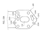
- the turbine 205 comprises a body 208 (in the present description also indicated, with analogous meaning, using the term "turbine body") including a first connection flange 209 in correspondence of which an inlet port 210 ( figure 15A ), a volute 211 and an outlet port 212 ( figure 16 ) end up.
- the turbine 205 comprises a wastegate valve controlled by an actuator, preferably pneumatic, (wastegate valve and respective actuator were removed for the sake of clarity).
- the compressor 206 comprises a body 213 (in the present description also indicated, with analogous meaning, using the term "compressor body”), an intake port 216, a volute 216A and an outlet port 217, in correspondence of which, analogously to the compressors 6, 106, a bypass valve (dump valve), herein removed for the sake of clarity, is mounted.
- a bypass valve dump valve
- the turbocharger assembly 204 comprises a stator assembly defined by the bodies 208, 213 and by the central body 207. Furthermore, the central body 207, the turbine body 208 and the compressor body 216 are made in a single piece.
- the rotor assembly 21 comprising the first impeller 22 rotatably mounted in the turbine body 208, the bearing pack 23 housed in the cavity 224, in which a lubrication channel 224A ends up by means of a hole 224B.
- the lubrication channel 24A is integrated in the stator assembly in correspondence of the connection flange 209, wherein it ends up with a terminal port 224C.
- the rotor assembly 21 further comprises the second impeller 25, rotatably mounted in the compressor body 213.
- the first and the second impeller 22, 25 are coaxial to the axis X and rotatably connected by means of the shaft 26.
- the rotor assembly 21 is arranged for the insertion in axial direction into the turbocharger assembly 204, particularly into the cavity 224.
- a jacket 234 in hydraulic communication with an inlet channel 234A and an outlet channel 234B integrated in the stator assembly in correspondence of the connection flange 209 and ending up thereon by means of respective terminal ports 234C, 234D.
- a collection channel 235 analogous to the channel 35 of the assemblies 4, 104 is provided in the stator assembly of the turbocharger assembly 204.
- the channel 235 is in part integrated within the connection flange 209 and ends up thereon with a terminal port 235A.
- four terminal ports 224C, 234C, 234D and 235A are provided in correspondence of the connection flange 209.
- the head 203 comprises an exhaust manifold 236 cast integrally therewith and fluid dynamically connected to exhaust conduits 237 associated to respective combustion chambers 238.
- the exhaust manifold 236 is surrounded by a first and a second cooling jacket 239, 240 which end up, by means of terminal ports 239A, 240A, in correspondence of a second connection flange 248. Furthermore, ending up in correspondence of the connection flange 248 are:
- terminal port 249 is connected to the pressurized branch of the lubrication circuit of the motor unit 210, while the port 250 is connected to a return branch of the lubricant, at low pressure.
- the turbocharger assembly 204 and the head 203 are coupled by means of mechanical connection of the first and of the second connection flanges 209, 248 (preferably by means of threaded joints 252): in such manner the flanges 209, 248 define a connection interface between the turbocharger assembly and the motor unit 201, in particular the head 203. Furthermore, the mechanical connection of the abovementioned flanges:
- the sleeve 43 is also mounted on the compressor body 213, in correspondence of the inlet port 216, in a manner entirely identical to that described regarding compressors 6, 106 ( figures 12-14 and 16-17 )
- the cooling fluid circulating in the engine 200 passes from the first cooling jacket 239 to the jacket 234 through the ports 239A, 234C and traverses the jacket 234 lowering the temperature of the turbine body 208 (and of the central body 207). Then, the cooling fluid flows out, at a higher temperature, from the jacket 234 through the ports 234D, 240A, and flows into the second cooling jacket 240, from which the circulation within the head 203 proceeds.
- the lubricating fluid particularly oil, conveyed under pressure to the terminal port 249, flows into the channel 224A through the port 224C, lubricates the rotor assembly 21 and it is collected in the collection channel 235 wherefrom, through the ports 235A, 250, it returns towards the cylinder block 2.
- the engine 200 preserves the advantages described previously, and additionally requires less complexity regarding the casting of the various parts, given that the turbocharger assembly 204 is separated from the head 203.
- the choice of the material of the turbine body 208 and of the central body 207 is wider, it is not bound to the use of the same material as the head 203, preferably an aluminium alloy.
- an aluminium alloy as well as gray cast iron may be used, hence avoiding expensive Nimonic® steels in any case.
Landscapes
- Engineering & Computer Science (AREA)
- Mechanical Engineering (AREA)
- General Engineering & Computer Science (AREA)
- Chemical & Material Sciences (AREA)
- Combustion & Propulsion (AREA)
- Chemical Kinetics & Catalysis (AREA)
- General Chemical & Material Sciences (AREA)
- Supercharger (AREA)
Abstract
- a motor unit (201) including a head (203) and an exhaust manifold (236),
- a turbocharger assembly (204) fluid dynamically connected to said exhaust manifold (236), wherein said turbocharger assembly (204) includes a turbine (205) with a turbine body (208), a central body (207) and a compressor (206) with a compressor body (213).
The turbocharger assembly (204) is separated from the motor unit (201; 203) and is arranged for a mechanical connection thereto (201, 203; 209, 248).
Furthermore, the central body (207), the turbine body (208) and the compressor body (216) are made in a single piece.
Description
- The present invention refers to a supercharged internal combustion engine comprising:
- a motor unit including a head and an exhaust manifold,
- a turbocharger assembly fluid dynamically connected to said exhaust manifold, wherein said turbocharger assembly includes a turbine with a turbine body, a central body and a compressor with a compressor body.
- Furthermore, a supercharged internal combustion engine according to the preamble of Claim 1 is known, e.g., from
US-A-2009/0151327 . - Supercharging internal combustion engines by means of turbocharger today plays a key role in the automotive industry due to the demand, by the market, for vehicles with lower environmental impact, low fuel consumption and at the same time offering good performance. In particular, currently the most common design trend among automotive producers is that of "downsizing", i.e. the reduction of the engine displacement, hence requiring, in order to guarantee good performance for vehicles on which the engines are installed, supercharging the same engines.
- However, supercharging by means of turbocharger entails several well known drawbacks. Apart from, for example, the well known problems related to knock control typical of spark ignition engines, the problems regarding the hydraulic connection between the turbocharger and the internal combustion engine for the circulation of oil and possibly cooling water within the central body of the turbocharger itself are of considerable importance.
- In fact, the internal combustion engines of the known type generally comprise one or more pipings having an end connected hydraulically and mechanically to the engine itself, for example to a cooling circuit or to a lubrication circuit, and a second end connected hydraulically and mechanically to inlet/outlet ports located on the central body of the turbocharger. The cost of such connections is quite high because each connection between an internal combustion engine and turbocharger implies the use of fittings, gaskets and fastening elements.
- Nevertheless, on spark ignition engines, the turbine body is made of high resistance steel with high contents of nickel (for example Nimonic® steel). Such steel is very expensive and the higher the nickel content the more expensive the steel. The higher the temperature of the exhaust gases flowing into the turbine, the higher the nickel amount required in such steels.
- Furthermore, there arises a related drawback typical of turbocharged engines: the body of the turbine, not cooled, reaches extremely high working temperatures, hence, combined with the considerable overall dimensions of the turbocharger assembly, it makes the installation of the latter complex, because it is necessary to envisage the use of protection panels for protecting the surrounding components from contact with the body of the turbine or from overexposure to a heat flow coming therefrom.
- Lastly, if on one hand there are drawbacks related to the high cost of some materials, to the working temperatures and upon installation of the turbocharger assembly, on the other hand there are problems regarding the high number of components required for the coupling of a turbocharger assembly to an internal combustion engine, as well as the high number of components that form the turbocharger assembly itself.
- The object of the present invention is that of overcoming the previously described drawbacks. In particular, the object of the invention is that of reducing the cost and the number of components required for producing and for coupling a turbocharger to the motor unit of an internal combustion engine, as well as that of optimising the operation of the turbo assembly in transient conditions of the engine following a cold start.
- The object of the present invention is attained by a turbocharged internal combustion engine having the features forming the subject of the claims that follow, which form an integral part of the technical disclosure provided herein in relation to the invention.
- In particular, the object of the present invention is attained by an internal combustion engine having the features of Claim 1.
- The invention will now be described with reference to the attached drawings, wherein:
-
figure 1 is a perspective view of an internal combustion engine not forming part of the present invention, -
figure 1A is a view according to arrow I offigure 1 , -
figure 2 is a view according to arrow II offigure 1 , -
figure 3 is a perspective view corresponding tofigure 1 but with some components removed for the sake of clarity, -
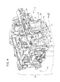
figure 4 is a view corresponding tofigure 2 with further components removed, -
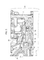
figure 5 is a sectional view according to line V-V offigure 4 , -
figure 6 is a sectional view according to line VI-VI offigure 3 , -
figure 7 is a view according to arrow VII offigure 4 , and -
figure 8 is a perspective view of a first variant of the internal combustion engine offigures 1-7 , not forming part of the invention, -
figure 8A is a view according to arrow VIII offigure 8 , -
figure 9 is a view according to arrow IX offigure 8 , -
figure 10 is a partly sectioned view according to line X-X offigure 8 , -
figure 11 is a view corresponding tofigure 8 but with some components removed for the sake of clarity -
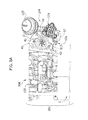
figure 12 is a perspective view of the internal combustion engine according to the present invention -
figure 13 is a perspective view according to arrow XIII offigure 12 ,
figure 14 is a view according to arrow XIV offigure 12 , -
figure 15 is a view corresponding tofigure 12 but with some components removed, -
figure 15A is a schematic view according to arrow XV offigure 12 , -
figure 16 is a perspective view partly sectioned according to line XVI-XVI offigure 12 , -
figure 17 is a view corresponding tofigure 16 but with some components removed for the sake of clarity, and -
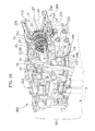
figure 18 is a sectional view according to line XVIII-XVIII offigure 15 . - The embodiments of
figures 1 to 11 do not form part of the present invention. However, such embodiments include components and/or structures which are also included in the embodiment offigures 12 to 18 that is part of the present invention. Where the description of such components and/or structures is provided in detail with reference to the embodiments not part of the invention, such description shall apply also to the embodiment part of the present invention. - An internal combustion engine not forming part of the present invention is indicated with 1 in
figures 1 ,1A ,2 ,3 . The internal combustion engine 1 comprises amotor unit 1A, in turn including acylinder block 2 and ahead 3, and aturbocharger assembly 4. Theturbocharger assembly 4 comprises aturbine 5, acompressor 6 and a central body 7 interposed between theturbine 5 and thecompressor 6. Theturbine 5 comprises abody 8 including a first and asecond portion body 8 will at times also be indicated using the term "turbine body", with an entirely equivalent meaning. - An inlet port (not visible) in fluid dynamic communication with a
volute 11 and with anoutlet port 12A of said turbine, are provided in said first andsecond portion turbine body 8 and it is actuated by means of anactuator 12B, preferably of the pneumatic type. - Analogously, the
compressor 6 comprises abody 13 including afirst portion 14 and asecond portion 15 and further comprises, provided in said first andsecond portion intake port 16, avolute 16A and anoutlet port 17. Abypass valve 17A (so-called "dump valve") of thecompressor 6 is fixed on theportion 15, in correspondence of theoutlet port 17. In the present description thebody 13 will also at times be indicated using the term "compressor body", with an entirely equivalent meaning. - The central body 7 comprises a first and a
second portion hole 19A provided on thesecond portion 19. Thefirst portions head 3. Thesecond portions head 3. Thus, theturbocharger assembly 4 substantially comprises a first and a second semi-shell A, B put close together along a separation plane C, preferably with the interposition of a gasket (or, alternatively a sealing paste), and fixed to each other by means of threadedjoints 20. In particular, the first semi-shell A is defined by thefirst portions turbine body 8, of thecompressor body 13 and of the central body 7, while the second semi-shell B, separable from the first semi-shell A, is defined by thesecond portions turbine body 8, of thecompressor body 13 and of the central body 7. - The joining of the two semi-shells A, B substantially provides a stator assembly of the
turbocharger assembly 4, i.e. an assembly of fixed parts. Thus theturbine body 8, thecompressor body 13 and the central body 7 are part of the stator assembly. - Referring to
figure 3 , a rotor assembly 21 - comprising afirst impeller 22 rotatably mounted inside theturbine body 8, a bearingpack 23 housed in acavity 24 of the central body 7 - is installed in theturbocharger assembly 4. Alubrication channel 24A arranged for the passage of a pressurised lubricating fluid and hydraulically connected with a lubrication circuit of the engine 1 ends up inside thecavity 24 in correspondence of ahole 24B. - The rotor assembly further comprises a
second impeller 25 rotatably mounted inside thebody 13 of thecompressor 6. The first and thesecond impeller shaft 26. - Referring to
figures 3 ,4 ,6 , in this embodiment the bearingpack 23 comprises asleeve 27 having aradial hole 27A and a plurality ofannular grooves radial channels internal cavity 32 provided in thesleeve 34. When therotor assembly 21 is inserted into thecavity 24, thegroove 29 is also positioned in correspondence with thehole 24B and theradial hole 27A is located in correspondence with thehole 19A. - The
shaft 26 which is rotatably supported by abushing 33 is inserted into theinternal cavity 32. In other embodiments, therotor assembly 21 comprises a bearing pack of the rolling type. In any case, generally there are many other options for providing thebearing pack 23. - A
jacket 34 arranged for the passage of a cooling fluid is provided in thebody 8 of theturbine 5 and partly in the central body 7. Furthermore, acollection channel 35 arranged for the collection of lubricating fluid and in direct hydraulic communication with thegrooves - The
jacket 34 and thechannel 35 are provided partly in semi-shell A, partly in semi-shell B. Each portion of thejacket 34 and of thechannel 35 is hydraulically connected to the respective portion provided on the second shell B when the first and the second shell A, B are joined together by means of the threaded joints 20. - Firstly, referring to
figure 5 and also tofigures 3 ,4 , thehead 3 comprises anexhaust manifold 36 fluid dynamically connected to exhaustconduits 37 associated to eachcombustion chamber 38 provided in thehead 3. Theexhaust manifold 36 is cast integrally with thehead 3 and it is surrounded by a cooling fluid circulating in a first and asecond cooling jacket motor unit 1A of the internal combustion engine 1. - The
jacket 34 provided within thebody 8 of theturbine 5 and partly within the central body 7 is hydraulically connected, by means of aninlet channel 41 and anoutlet channel 42 respectively to the first and to thesecond cooling jacket - The inlet and
outlet channels turbocharger assembly 4, particularly in the stator assembly, in correspondence of a connection interface between theturbocharger assembly 4 itself and the internal combustion engine 1. - In the present description, the term "connection interface" is used to indicate a physical or geometric surface (ideal) along which the
turbocharger assembly 4 and themotor unit 1A of the internal combustion engine 1, particularly the stator assembly of theturbocharger assembly 4 are joined to thehead 3 of themotor unit 1A. - Thus, in the embodiment described herein, the connection interface between the
turbocharger assembly 4 and thehead 3 is a surface which ideally separates the semi-shell A from thehead 3 though they are integrally cast together. Analogously, thechannel 24A hydraulically connected to a lubrication circuit of themotor unit 1A is integrated in theturbocharger 4, particularly in the stator assembly, in correspondence of the abovementioned connection interface. - In other words, assuming to ideally separate the stator assembly from the head 3 (or, generally from the
motor unit 1A) along the abovementioned connection interface (thus obtaining two complementary separation surfaces, one on the stator assembly and one on the head), the result would be a stator assembly having a series of terminal ports ending up on the separation surface thereof and corresponding, respectively, tochannels channels jackets motor unit 1A, wherein the terminal ports of the stator assembly and of the head would evidently be in homologous positions (the association is between thechannels jackets channels 24A, 53 with the channels connected to the lubrication circuit of themotor unit 1A of the engine 1, whose type will be addressed further ahead). The interface between the two separation surfaces is evidently the abovementioned "connection interface". - Furthermore, a
sleeve 43 having aninternal channel 44 and afastening flange 45 rigidly connected to thebody 13 of thecompressor 6 by means of threadedjoints 46 is mounted in correspondence of theinlet port 16. It should be observed that the diameter of thechannel 44 defines the geometric passage section in theinlet port 16. Thesleeve 43 is inserted into ahole 47 provided on thebody 13 of thecompressor 6 in correspondence of theinlet port 16. - The internal combustion engine 1 operates as follows.
- The exhaust gases which are generated following the combustion of the air/fuel mixture inside the
combustion chambers 38 traverse theexhaust conduits 37 and are collected by theexhaust manifold 36, which is fluid dynamically connected with the inlet port of theturbine 5. - Thus, the exhaust gases flowing out into the
volute 11 and flowing out from theoutlet port 12 rotate thefirst impeller 22 which thanks to theshaft 26 brings thesecond impeller 25 in rotation. The latter intakes air through theinlet port 16, particularly through thechannel 44 and conveys it, compressing it, into thebody 13 of thecompressor 6 wherefrom, through theoutlet port 17, it is delivered to the intake of the internal combustion engine 1, typically after an intercooling step. - The
head 3 is preferably made of an aluminium alloy as well as the shells A, B. In order to avoid the melting of the stator assembly, particularly theturbine body 8, due to the high temperatures reached by the exhaust gases, both in the case of compression ignition engines and in the case of spark ignition engines (for which the exhaust temperatures are definitely higher), a cooling fluid coming from the internal combustion engine 1 passes from thejacket 39 through theinlet channel 41 and flows into thejacket 34 within theturbine body 8 and within part of the central body 7. - Thus, the water traverses the
jacket 34 and cools thebody 8 and the central body 7 flowing out at a higher temperature through theoutlet channel 42 and then returns to the cooling circuit of themotor unit 1A through thejacket 40. - Simultaneously, the
lubrication channel 24A, in hydraulic communication with the lubrication circuit of themotor unit 1A, contains lubricating fluid, particularly lubricating oil, which through thegroove 29 and thecorresponding channel 31B lubricates theinternal cavity 41 and thebushing 42, allowing high rotation speeds of theshaft 26 and of theimpellers - The lubricating oil is then forced towards the
radial channels annular grooves channel 35 for recirculation within the lubrication circuit. Thechannel 35 is in fact hydraulically connected to a return line of the lubricant which propagates from thehead 3 towards thecylinder block 2. It should be observed that the heating of the oil is prevented by the cooling fluid which circulates in thejacket 34 and which lowers the temperature of theturbine body 8 and also of the central body 7. - The internal combustion engine 1 has a considerable number of advantages with respect to the internal combustion engines of the known type.
- In the first place, the pipings, the fittings and the gaskets required for the hydraulic connection between the channels for the lubricating fluid and the cooling fluid normally located on the central body of the turbochargers of supercharged engines of the known type are eliminated. Furthermore, the number of components that form the
turbocharger assembly 5 is considerably lower with respect to the internal combustion engines of the known type, given that theturbocharger assembly 5 substantially comprises the first and the second shell A, B, therotor assembly 23 and thesleeve 43. This, combined with the elimination of the pipings, the fittings and the gaskets allows considerably reducing the production costs of theturbocharger assembly 5 and of the entire internal combustion engine 1. - However, given that the shells A, B are preferably made of aluminium, it is also possible to obtain considerable saving on the type of material. Actually, by using the
jacket 34 for cooling the turbine body 8 (and the central body 7), it is possible to avoid using the expensive Nimonic® superalloys to the advantage of using aluminium which has a definitely much lower cost. - In addition to what has been described above, it should also be observed that the internal combustion engine 1 also has several indisputable advantages in terms of the mechanical machining operations on the
turbocharger assembly 4. Actually, in order to obtain mechanical machining operations that are accurate and capable of ensuring the dimensional tolerances required for such application, a preferred machining method for theturbocharger assembly 4 is the following. - The
head 3 and the shell A, provided in a single piece, are temporarily joined to the shell B, provided separately. In this step, neither thesleeve 43 nor therotor assembly 21 are assembled. - The
internal cavity 24 of the central body 7 is thus machined, for example by means of various types of tools (for example boring tools or the like), to obtain the combination of surface finishing and geometric tolerances required for the insertion of therotor assembly 21. - Then, after the temporary separation of the two shells A, B for the removal of chips possibly accumulated following the mechanical finishing, the two semi-shells are put close together once again and fastened by means of threaded
joints 20, therotor assembly 21 pre-assembled as shown infigure 3 is inserted axially along the axis X through thehole 47. In particular, the diameter of thehole 47 must be sufficiently wide to allow the insertion of therotor assembly 21. The axial blocking of therotor assembly 21 inside thecavity 24 is ensured by inserting a pin or a threaded dowel into theholes cavity 24. - Lastly, the
sleeve 43 is fitted into thehole 47 and it is fastened to theturbocharger assembly 4 by means of the threaded joints 46. - Referring to
figures 8 ,8A ,9 , an advantageous variant of an internal combustion engine offigures 1-7 is indicated with 100. The components identical to those described previously regarding the internal combustion engine 1 are indicated using the same reference number. Theinternal combustion engine 100 comprises amotor unit 101, in turn including thecylinder block 2 and ahead 103, and aturbocharger assembly 104. - The
turbocharger assembly 104 comprises aturbine 105, acompressor 106 and acentral body 107 interposed therebetween. Theturbine 105 and thecompressor 106 compriserespective bodies central body 107. In the present description, thebody 108 of theturbine 105 will at times be indicated using the term "turbine body", with an equivalent meaning. - Similarly, the
body 113 of thecompressor 106 will at times be indicated using the term "compressor body", with an equivalent meaning. - Analogously to the
turbocharger assembly 4, thebodies turbocharger assembly 104. - The
bodies central body 107 are cast integrally with thehead 103. It should be observed that, substantially, this variant differs from the internal combustion engine 1 solely due to the fact that the stator assembly of theturbocharger assembly 104 does not comprise the semi-shells A, B, which - on the contrary - are made in a single piece together and with thehead 103. - The
head 103 is furthermore substantially identical in the structure outside and inside the head 3 - in particular it comprises theexhaust manifold 36 integrally cast therein and fluid dynamically connected to an inlet port of theturbine 105 and thejackets 39, 40 - obviously except for the fact that the entire stator assembly of theturbocharger assembly 104 is integral therewith, not a single semi-shell as in the case of thehead 3. - The internal structure of the turbocharger assembly 104 (
figure 10, 11 )is also identical, wherein - the
turbine 105 comprises thevolute 11, theoutlet port 12, thewastegate valve 12B and thejacket 34, which are in such case provided without interruption in theturbine body 108 and in part of thecentral body 107, - the
compressor 106 comprises, all provided without interruption, theinlet port 16, thevolute 16A, theoutlet port 17 and the bypass valve (dump valve) 17A; - the
central body 107, alongside a part of thejacket 34, comprises thehole 19A, and thecavity 24 with thelubrication channel 24A and thehole 24B, wherein thecavity 24 accommodates therotor assembly 21 comprising the bearingpack 23, thefirst impeller 22 rotatably mounted within theturbine body 108 and thesecond impeller 25 rotatably mounted within thecompressor body 113. - Furthermore, the
collection channel 35, also in this case provided without interruption, is arranged in correspondence of thecentral body 107. - Analogously to the internal combustion engine 1, the
sleeve 43 inserted into thehole 47 provided in thecompressor body 113 and flanged to thesame compressor body 113 by means of the threadedjoints 46 is furthermore present. - The method for machining and mounting the
turbocharger assembly 104 is substantially identical to that described regarding theturbocharger assembly 4, with the obvious absence of the step of temporarily joining the shells A, B which are in such case made in a single piece together. Analogously to theturbocharger assembly 4, therotor assembly 21 is axially inserted through thehole 47 in theinternal cavity 24, and it is axially blocked by means of a pin or threaded dowel inserted into theholes - It should also be observed that the geometry of the turbocharger assembly may vary slightly with respect to what has been illustrated by way of example given that, depending on the process used for the casting of the
head 103 and of the turbocharger assembly 104 (for example die casting or lost foam casting), it may require arranging one or more holes, for supporting the casting cores, subsequently closable by means of plugs. - The
engine 100 preserves the same advantages described regarding the internal combustion engine 1 and it further amplifies some of them. In particular, the number of components required for assembling theturbocharger assembly 104 is further reduced in this case because the stator assembly is substantially cast integrally with thehead 103 and both are preferably made of an aluminium alloy. - Referring to
figures 12 to 18 , a turbocharged internal combustion engine according to the present invention is indicated with 200. The components identical to those described previously regarding theengines 1, 100 are indicated using the same reference number and have an analogous function. - The
internal combustion engine 200 comprises amotor unit 201, in turn including thecylinder block 2 and ahead 203, and aturbocharger assembly 204. Theturbocharger assembly 204 comprises aturbine 205, acompressor 206 and acentral body 207 interposed therebetween. Theturbine 205 comprises a body 208 (in the present description also indicated, with analogous meaning, using the term "turbine body") including afirst connection flange 209 in correspondence of which an inlet port 210 (figure 15A ), avolute 211 and an outlet port 212 (figure 16 ) end up. Analogously to theturbines turbine 205 comprises a wastegate valve controlled by an actuator, preferably pneumatic, (wastegate valve and respective actuator were removed for the sake of clarity). - Referring to
figures 12 ,16 , thecompressor 206 comprises a body 213 (in the present description also indicated, with analogous meaning, using the term "compressor body"), anintake port 216, avolute 216A and anoutlet port 217, in correspondence of which, analogously to thecompressors - Similarly to the
turbocharger assemblies turbocharger assembly 204 comprises a stator assembly defined by thebodies central body 207. Furthermore, thecentral body 207, theturbine body 208 and thecompressor body 216 are made in a single piece. - Referring to
figures 16 ,17 , within thecentral body 207 there is housed therotor assembly 21 comprising thefirst impeller 22 rotatably mounted in theturbine body 208, the bearingpack 23 housed in thecavity 224, in which alubrication channel 224A ends up by means of ahole 224B. Thelubrication channel 24A is integrated in the stator assembly in correspondence of theconnection flange 209, wherein it ends up with aterminal port 224C. - The
rotor assembly 21 further comprises thesecond impeller 25, rotatably mounted in thecompressor body 213. The first and thesecond impeller shaft 26. - The further components of the
rotor assembly 21 will not be described in detail again because they are identical to those described previously. Furthermore, analogously to what has been described previously, therotor assembly 21 is arranged for the insertion in axial direction into theturbocharger assembly 204, particularly into thecavity 224. - Referring to
figures 15A ,16 ,17 , within theturbine body 208 and in part within thecentral body 207 there is provided ajacket 234 in hydraulic communication with aninlet channel 234A and anoutlet channel 234B integrated in the stator assembly in correspondence of theconnection flange 209 and ending up thereon by means of respectiveterminal ports collection channel 235 analogous to thechannel 35 of theassemblies turbocharger assembly 204. Thechannel 235 is in part integrated within theconnection flange 209 and ends up thereon with aterminal port 235A. Substantially, fourterminal ports connection flange 209. - Referring to
figures 15 ,18 , thehead 203 comprises anexhaust manifold 236 cast integrally therewith and fluid dynamically connected to exhaustconduits 237 associated torespective combustion chambers 238. - The
exhaust manifold 236 is surrounded by a first and asecond cooling jacket terminal ports second connection flange 248. Furthermore, ending up in correspondence of theconnection flange 248 are: - two
terminal ports motor unit 201 of theengine 200 and in positions homologous to those of the terminal ports, respectively, 224C and 235A; - the
exhaust manifold 236 by means of anoutlet port 251 substantially shaped identically to theinlet port 210 on theflange 209 and in homologous position with respect thereto. - In particular, the
terminal port 249 is connected to the pressurized branch of the lubrication circuit of themotor unit 210, while theport 250 is connected to a return branch of the lubricant, at low pressure. - The
turbocharger assembly 204 and thehead 203 are coupled by means of mechanical connection of the first and of thesecond connection flanges 209, 248 (preferably by means of threaded joints 252): in such manner theflanges motor unit 201, in particular thehead 203. Furthermore, the mechanical connection of the abovementioned flanges: - fluid dynamically connects the
outlet port 251 to theinlet port 210 of theturbine 205; - hydraulically connects the
terminal ports terminal ports jacket 234 to thejackets motor unit 201 of theinternal combustion engine 200; - hydraulically connects the
terminal ports terminal ports lubrication channel 224A and thecollection channel 235 to the lubrication circuit of themotor unit 201 of the internal combustion engine. - The
sleeve 43 is also mounted on thecompressor body 213, in correspondence of theinlet port 216, in a manner entirely identical to that described regardingcompressors 6, 106 (figures 12-14 and16-17 ) - Regarding the operation of the
engine 200, the methods through which the two impellers are brought in rotation by means of the exhaust gases are substantially identical with respect to what has been described regarding the engine 1. - In order to prevent the melting of the stator assembly due to the high operating temperatures of the
turbine 205, the cooling fluid circulating in theengine 200 passes from thefirst cooling jacket 239 to thejacket 234 through theports jacket 234 lowering the temperature of the turbine body 208 (and of the central body 207). Then, the cooling fluid flows out, at a higher temperature, from thejacket 234 through theports second cooling jacket 240, from which the circulation within thehead 203 proceeds. - Similarly, the lubricating fluid, particularly oil, conveyed under pressure to the
terminal port 249, flows into thechannel 224A through theport 224C, lubricates therotor assembly 21 and it is collected in thecollection channel 235 wherefrom, through theports cylinder block 2. - Also the
engine 200 preserves the advantages described previously, and additionally requires less complexity regarding the casting of the various parts, given that theturbocharger assembly 204 is separated from thehead 203. - However, the choice of the material of the
turbine body 208 and of thecentral body 207 is wider, it is not bound to the use of the same material as thehead 203, preferably an aluminium alloy. Actually, an aluminium alloy as well as gray cast iron may be used, hence avoiding expensive Nimonic® steels in any case. - Naturally, the details and embodiments may vary, even significantly, with respect to what has been described and illustrated purely by way of example, without departing from the scope of the present invention as defined by the attached.
Claims (6)
- A supercharged internal combustion engine (200) comprising:- a motor unit (201) including a head (203) and an exhaust manifold (236),- a turbocharger assembly (204) fluid dynamically connected to said exhaust manifold (236), wherein said turbocharger assembly (204) includes a turbine (205) with a turbine body (208), a central body (207) and a compressor (206) with a compressor body (213),wherein- said turbocharger assembly (204) comprises a lubrication channel (224A) for the passage of a lubricating fluid hydraulically connected to a lubrication circuit of said motor unit (201) of said internal combustion engine (200),- said turbine (205) comprises a jacket (234), provided at least in part in said turbine body (208), arranged for the passage of a cooling fluid and in hydraulic communication with an inlet channel (234A) and an outlet channel (234B) hydraulically connected to a cooling circuit (239, 240) of said motor unit (201) of said internal combustion engine (200),- said inlet channel (234A), outlet channel (42, 234B) and lubrication channel (224A) being integrated in said turbocharger assembly (204) in correspondence of a connection portion between said turbocharger assembly (204) and said motor unit (201) of said internal combustion engine (200),the internal combustion engine (200) being characterized in that
said turbocharger assembly (204) is separated from said motor unit (201; 203) and is arranged for a mechanical connection to said motor unit (201, 203; 209, 248), and
in that the central body (207), the turbine body (208) and the compressor body (216) are made in a single piece. - The internal combustion engine (1, 100, 200) according to Claim 1, wherein said central body (7, 107, 207) comprises a cavity (24, 224) wherein a rotor assembly (21) of said turbocharger assembly (4, 104, 204) is housed and
wherein said rotor assembly (21) comprises a first impeller (22) rotatably mounted within said turbine body (208), a bearing pack (23) and a second impeller (25) rotatably mounted in said compressor body (216), wherein said first and said second impellers (22, 25) are connected in rotation by means of a shaft (26). - The internal combustion engine (200) according to Claim 2, characterized in that said bearing pack (23) comprises a sleeve (27) including annular grooves (28, 29, 30) in hydraulic communication, by means of radial channels (31A, 31B, 31C) with an internal cavity (32) provided in said sleeve (27), wherein said shaft (26) is inserted in said internal cavity (32) rotatably supported by a bushing (33).
- The internal combustion engine (200) according to Claim 2, characterized in that said rotor assembly (21) is arranged for the insertion in axial direction into said turbocharger assembly ( 204).
- The internal combustion engine (200) according to Claim 1, characterized in that said compressor (206) comprises an inlet port ( 216) in correspondence of which there is mounted a sleeve (43) having an internal channel (44) and a fastening flange (45) rigidly connected to the compressor body (213).
- The internal combustion engine (200) according to Claim 1, characterized in that said head (203) comprises an exhaust manifold (236) integrally cast therein (203).
Applications Claiming Priority (2)
| Application Number | Priority Date | Filing Date | Title |
|---|---|---|---|
| ITTO2010A000498A IT1400446B1 (en) | 2010-06-11 | 2010-06-11 | MOTOR WITH INTERNAL COMBUSTION OVERHEADED |
| EP10425205.1A EP2402577B1 (en) | 2010-06-11 | 2010-06-16 | Supercharged internal combustion engine |
Related Parent Applications (2)
| Application Number | Title | Priority Date | Filing Date |
|---|---|---|---|
| EP10425205.1 Division | 2010-06-16 | ||
| EP10425205.1A Division EP2402577B1 (en) | 2010-06-11 | 2010-06-16 | Supercharged internal combustion engine |
Publications (2)
| Publication Number | Publication Date |
|---|---|
| EP2405112A1 true EP2405112A1 (en) | 2012-01-11 |
| EP2405112B1 EP2405112B1 (en) | 2018-05-23 |
Family
ID=43448776
Family Applications (3)
| Application Number | Title | Priority Date | Filing Date |
|---|---|---|---|
| EP11162492.0A Active EP2405112B1 (en) | 2010-06-11 | 2010-06-16 | Supercharged internal combustion engine |
| EP10425205.1A Active EP2402577B1 (en) | 2010-06-11 | 2010-06-16 | Supercharged internal combustion engine |
| EP11162501.8A Active EP2405113B1 (en) | 2010-06-11 | 2010-06-16 | Supercharged internal combustion engine |
Family Applications After (2)
| Application Number | Title | Priority Date | Filing Date |
|---|---|---|---|
| EP10425205.1A Active EP2402577B1 (en) | 2010-06-11 | 2010-06-16 | Supercharged internal combustion engine |
| EP11162501.8A Active EP2405113B1 (en) | 2010-06-11 | 2010-06-16 | Supercharged internal combustion engine |
Country Status (4)
| Country | Link |
|---|---|
| US (1) | US8572963B2 (en) |
| EP (3) | EP2405112B1 (en) |
| IT (1) | IT1400446B1 (en) |
| WO (1) | WO2011154874A2 (en) |
Families Citing this family (32)
| Publication number | Priority date | Publication date | Assignee | Title |
|---|---|---|---|---|
| EP2526274A4 (en) | 2010-01-22 | 2017-05-17 | BorgWarner Inc. | Directly communicated turbocharger |
| DE102011101506B4 (en) * | 2010-05-17 | 2015-06-18 | GM Global Technology Operations LLC (n. d. Ges. d. Staates Delaware) | Motor assembly and method of manufacture |
| ITTO20100496A1 (en) | 2010-06-11 | 2011-12-12 | Zeca S P A | LIGHTING DEVICE |
| US20130000299A1 (en) * | 2011-06-30 | 2013-01-03 | Caterpillar Inc. | Heat shield apparatus |
| US8966894B2 (en) * | 2012-03-21 | 2015-03-03 | Honeywell International Inc. | Turbocharger cartridge and engine cylinder head assembly |
| US8966895B2 (en) | 2012-03-21 | 2015-03-03 | Honeywell International Inc. | Turbocharger cartridge, bypass, and engine cylinder head assembly |
| US9091200B2 (en) | 2012-03-21 | 2015-07-28 | Honeywell International Inc. | Turbocharger and engine cylinder head assembly |
| US8955318B2 (en) | 2012-03-21 | 2015-02-17 | Honeywell International Inc. | Turbocharger cartridge and engine cylinder head assembly |
| EP2703623A3 (en) * | 2012-08-28 | 2018-03-28 | Honeywell International Inc. | Turbocharger and engine cylinder head assembly |
| CH707886A1 (en) * | 2013-04-12 | 2014-10-15 | Liebherr Machines Bulle Sa | Drive system. |
| CN104541032B (en) * | 2013-06-17 | 2017-03-08 | 丰田自动车株式会社 | The chiller of internal-combustion engine system and its control method |
| US9206733B2 (en) * | 2013-06-28 | 2015-12-08 | GM Global Technology Operations LLC | Turbocharger assembly with direct-mounted bearing housing |
| WO2016000732A1 (en) | 2014-07-04 | 2016-01-07 | Volvo Truck Corporation | A turbocharger unit |
| US9683520B2 (en) | 2015-03-09 | 2017-06-20 | Caterpillar Inc. | Turbocharger and method |
| US9777747B2 (en) | 2015-03-09 | 2017-10-03 | Caterpillar Inc. | Turbocharger with dual-use mounting holes |
| US9638138B2 (en) | 2015-03-09 | 2017-05-02 | Caterpillar Inc. | Turbocharger and method |
| US9879594B2 (en) | 2015-03-09 | 2018-01-30 | Caterpillar Inc. | Turbocharger turbine nozzle and containment structure |
| US9903225B2 (en) | 2015-03-09 | 2018-02-27 | Caterpillar Inc. | Turbocharger with low carbon steel shaft |
| US9752536B2 (en) | 2015-03-09 | 2017-09-05 | Caterpillar Inc. | Turbocharger and method |
| US10066639B2 (en) | 2015-03-09 | 2018-09-04 | Caterpillar Inc. | Compressor assembly having a vaneless space |
| US9822700B2 (en) | 2015-03-09 | 2017-11-21 | Caterpillar Inc. | Turbocharger with oil containment arrangement |
| US9650913B2 (en) | 2015-03-09 | 2017-05-16 | Caterpillar Inc. | Turbocharger turbine containment structure |
| US9915172B2 (en) | 2015-03-09 | 2018-03-13 | Caterpillar Inc. | Turbocharger with bearing piloted compressor wheel |
| US9810238B2 (en) | 2015-03-09 | 2017-11-07 | Caterpillar Inc. | Turbocharger with turbine shroud |
| US9732633B2 (en) | 2015-03-09 | 2017-08-15 | Caterpillar Inc. | Turbocharger turbine assembly |
| US10006341B2 (en) | 2015-03-09 | 2018-06-26 | Caterpillar Inc. | Compressor assembly having a diffuser ring with tabs |
| US9890788B2 (en) | 2015-03-09 | 2018-02-13 | Caterpillar Inc. | Turbocharger and method |
| US9739238B2 (en) | 2015-03-09 | 2017-08-22 | Caterpillar Inc. | Turbocharger and method |
| US12078078B2 (en) * | 2015-11-09 | 2024-09-03 | Fca Us Llc | Cylinder head with integrated turbocharger |
| CN108266283B (en) * | 2018-02-01 | 2024-03-19 | 成都桐林铸造实业有限公司 | Supercharged engine cylinder body and automobile engine |
| US10774874B2 (en) * | 2018-08-06 | 2020-09-15 | General Electric Company | Fluid bearing assembly |
| US20200347773A1 (en) * | 2019-05-02 | 2020-11-05 | Michael P Schmidt | Cylinder head with integrated turbocharger |
Citations (5)
| Publication number | Priority date | Publication date | Assignee | Title |
|---|---|---|---|---|
| FR2491130A1 (en) * | 1980-09-29 | 1982-04-02 | Kronogard Sven Olof | INTEGRATED TURBOCHARGER CYLINDER HEAD |
| JPS6322346U (en) * | 1986-07-29 | 1988-02-15 | ||
| EP0752055A1 (en) * | 1994-03-19 | 1997-01-08 | Schwitzer (Europe) Limited | Turbochargers |
| US20090151327A1 (en) | 2007-12-14 | 2009-06-18 | Gm Global Technology Operations, Inc. | Turbocharger and cylinder head |
| EP2143925A1 (en) * | 2008-07-11 | 2010-01-13 | Ford Global Technologies, LLC | Assembly with cylinder head and turbine |
Family Cites Families (23)
| Publication number | Priority date | Publication date | Assignee | Title |
|---|---|---|---|---|
| US1903210A (en) * | 1929-02-28 | 1933-03-28 | Carrier Engineering Corp | Sealing and thrust balancing means |
| DE2252705A1 (en) * | 1972-10-27 | 1974-05-02 | Daimler Benz Ag | MOUNTING OF AN EXHAUST TURBOCHARGER TO A COMBUSTION ENGINE |
| US4068612A (en) * | 1976-01-26 | 1978-01-17 | M & W Gear Company | Turbocharger housing construction for marine turbocharger and device for turbocharging a marine engine |
| JPS5752624A (en) * | 1980-09-16 | 1982-03-29 | Honda Motor Co Ltd | Supercharger unit in motor cycle |
| US4474007A (en) * | 1980-09-29 | 1984-10-02 | Ab Volvo | Turbocharging device for an internal combustion engine |
| SE446114B (en) * | 1980-09-29 | 1986-08-11 | Volvo Ab | DEVICE OF A COMBUSTION ENGINE |
| US4721398A (en) * | 1985-08-22 | 1988-01-26 | Ishikawajima-Harima Jokogyo Kabushiki Kaisha | Bearing device for rotary machine |
| DE3532695C1 (en) * | 1985-09-13 | 1986-11-27 | Audi AG, 8070 Ingolstadt | Exhaust gas turbocharger for a vehicle internal combustion engine |
| AU763398B2 (en) * | 1998-08-19 | 2003-07-24 | Shuttleworth Axial Motor Company Limited | Improvements relating to axial two-stroke motors |
| WO2001065091A1 (en) * | 2000-02-29 | 2001-09-07 | Bombardiers-Rotax Gmbh | Four stroke engine having flexible arrangement |
| JP2002303145A (en) * | 2001-04-05 | 2002-10-18 | Toyota Motor Corp | Internal combustion engine with turbo-charger |
| JP2002364375A (en) * | 2001-06-05 | 2002-12-18 | Fuji Heavy Ind Ltd | Supercharger mounting structure for engine |
| DE50303860D1 (en) * | 2003-11-28 | 2006-07-27 | Borgwarner Inc | Casing for turbocharger |
| JP2006063851A (en) * | 2004-08-25 | 2006-03-09 | Toyota Motor Corp | Turbocharger-incorporated cylinder head |
| JP2006194227A (en) * | 2005-01-17 | 2006-07-27 | Toyota Motor Corp | Turbo supercharger for internal combustion engine |
| JP2006249945A (en) * | 2005-03-08 | 2006-09-21 | Toyota Motor Corp | Internal combustion engine with turbocharger |
| JP4692820B2 (en) * | 2005-08-11 | 2011-06-01 | 株式会社Ihi | Supercharger with electric motor |
| US7677041B2 (en) * | 2006-10-11 | 2010-03-16 | Woollenweber William E | Bearing systems for high-speed rotating machinery |
| DE102007017854A1 (en) * | 2007-04-16 | 2008-10-30 | Siemens Ag | Internal combustion engine |
| JP4947007B2 (en) * | 2008-08-07 | 2012-06-06 | トヨタ自動車株式会社 | Internal combustion engine with a supercharger |
| JP4725656B2 (en) * | 2009-02-13 | 2011-07-13 | マツダ株式会社 | Exhaust passage structure of multi-cylinder engine |
| US7946118B2 (en) * | 2009-04-02 | 2011-05-24 | EcoMotors International | Cooling an electrically controlled turbocharger |
| EP2526274A4 (en) * | 2010-01-22 | 2017-05-17 | BorgWarner Inc. | Directly communicated turbocharger |
-
2010
- 2010-06-11 IT ITTO2010A000498A patent/IT1400446B1/en active
- 2010-06-16 EP EP11162492.0A patent/EP2405112B1/en active Active
- 2010-06-16 EP EP10425205.1A patent/EP2402577B1/en active Active
- 2010-06-16 EP EP11162501.8A patent/EP2405113B1/en active Active
-
2011
- 2011-06-01 WO PCT/IB2011/052417 patent/WO2011154874A2/en active Application Filing
- 2011-06-06 US US13/153,935 patent/US8572963B2/en not_active Ceased
Patent Citations (5)
| Publication number | Priority date | Publication date | Assignee | Title |
|---|---|---|---|---|
| FR2491130A1 (en) * | 1980-09-29 | 1982-04-02 | Kronogard Sven Olof | INTEGRATED TURBOCHARGER CYLINDER HEAD |
| JPS6322346U (en) * | 1986-07-29 | 1988-02-15 | ||
| EP0752055A1 (en) * | 1994-03-19 | 1997-01-08 | Schwitzer (Europe) Limited | Turbochargers |
| US20090151327A1 (en) | 2007-12-14 | 2009-06-18 | Gm Global Technology Operations, Inc. | Turbocharger and cylinder head |
| EP2143925A1 (en) * | 2008-07-11 | 2010-01-13 | Ford Global Technologies, LLC | Assembly with cylinder head and turbine |
Also Published As
| Publication number | Publication date |
|---|---|
| WO2011154874A3 (en) | 2012-05-18 |
| US20110302920A1 (en) | 2011-12-15 |
| EP2402577A1 (en) | 2012-01-04 |
| EP2405113B1 (en) | 2017-06-07 |
| IT1400446B1 (en) | 2013-05-31 |
| EP2405112B1 (en) | 2018-05-23 |
| ITTO20100498A1 (en) | 2011-12-12 |
| EP2402577B1 (en) | 2013-05-29 |
| WO2011154874A2 (en) | 2011-12-15 |
| US8572963B2 (en) | 2013-11-05 |
| EP2405113A1 (en) | 2012-01-11 |
Similar Documents
| Publication | Publication Date | Title |
|---|---|---|
| EP2405112B1 (en) | Supercharged internal combustion engine | |
| US10670029B2 (en) | Multi-segment turbocharger bearing housing and methods therefor | |
| EP2050940B1 (en) | Method of manufacturing assembling and mounting a multi-stage supercharging exhaust turbosupercharger | |
| EP2966271B1 (en) | Turbocharger turbine housing | |
| EP2655829B1 (en) | Engine cylinder head and turbocharger assembly | |
| CA2448451C (en) | Turbocharged internal combustion engine | |
| US5803719A (en) | Turbocharged internal combustion engine | |
| CN102803678A (en) | Multi-stage turbocharger arrangement | |
| EP2828498B1 (en) | Turbocharger cartridge and engine cylinder head assembly | |
| WO2007135449A1 (en) | A turbine for a turbocharger | |
| WO2012051085A2 (en) | Exhaust turbocharger | |
| US20150034029A1 (en) | Internal combustion engine having at least one cylinder | |
| US11555439B2 (en) | Cylinder head with integrated turbocharger | |
| USRE46074E1 (en) | Supercharged internal combustion engine | |
| EP2395213B1 (en) | Supercharged internal combustion engine with an integrated coupling flange for a turbosupercharger | |
| US12078078B2 (en) | Cylinder head with integrated turbocharger | |
| US20220112860A1 (en) | Cylinder head with integrated turbocharger | |
| US11680516B2 (en) | Multi-stage turbocharging assembly |
Legal Events
| Date | Code | Title | Description |
|---|---|---|---|
| 17P | Request for examination filed |
Effective date: 20110909 |
|
| AC | Divisional application: reference to earlier application |
Ref document number: 2402577 Country of ref document: EP Kind code of ref document: P |
|
| AK | Designated contracting states |
Kind code of ref document: A1 Designated state(s): AL AT BE BG CH CY CZ DE DK EE ES FI FR GB GR HR HU IE IS IT LI LT LU LV MC MK MT NL NO PL PT RO SE SI SK SM TR |
|
| AX | Request for extension of the european patent |
Extension state: BA ME RS |
|
| PUAI | Public reference made under article 153(3) epc to a published international application that has entered the european phase |
Free format text: ORIGINAL CODE: 0009012 |
|
| 17Q | First examination report despatched |
Effective date: 20161018 |
|
| STAA | Information on the status of an ep patent application or granted ep patent |
Free format text: STATUS: EXAMINATION IS IN PROGRESS |
|
| GRAP | Despatch of communication of intention to grant a patent |
Free format text: ORIGINAL CODE: EPIDOSNIGR1 |
|
| STAA | Information on the status of an ep patent application or granted ep patent |
Free format text: STATUS: GRANT OF PATENT IS INTENDED |
|
| INTG | Intention to grant announced |
Effective date: 20180212 |
|
| GRAS | Grant fee paid |
Free format text: ORIGINAL CODE: EPIDOSNIGR3 |
|
| GRAA | (expected) grant |
Free format text: ORIGINAL CODE: 0009210 |
|
| STAA | Information on the status of an ep patent application or granted ep patent |
Free format text: STATUS: THE PATENT HAS BEEN GRANTED |
|
| REG | Reference to a national code |
Ref country code: FR Ref legal event code: PLFP Year of fee payment: 9 |
|
| AC | Divisional application: reference to earlier application |
Ref document number: 2402577 Country of ref document: EP Kind code of ref document: P |
|
| AK | Designated contracting states |
Kind code of ref document: B1 Designated state(s): AL AT BE BG CH CY CZ DE DK EE ES FI FR GB GR HR HU IE IS IT LI LT LU LV MC MK MT NL NO PL PT RO SE SI SK SM TR |
|
| REG | Reference to a national code |
Ref country code: GB Ref legal event code: FG4D |
|
| REG | Reference to a national code |
Ref country code: CH Ref legal event code: EP |
|
| REG | Reference to a national code |
Ref country code: IE Ref legal event code: FG4D |
|
| REG | Reference to a national code |
Ref country code: DE Ref legal event code: R096 Ref document number: 602010050840 Country of ref document: DE |
|
| REG | Reference to a national code |
Ref country code: AT Ref legal event code: REF Ref document number: 1001709 Country of ref document: AT Kind code of ref document: T Effective date: 20180615 |
|
| REG | Reference to a national code |
Ref country code: NL Ref legal event code: MP Effective date: 20180523 |
|
| REG | Reference to a national code |
Ref country code: LT Ref legal event code: MG4D |
|
| PG25 | Lapsed in a contracting state [announced via postgrant information from national office to epo] |
Ref country code: FI Free format text: LAPSE BECAUSE OF FAILURE TO SUBMIT A TRANSLATION OF THE DESCRIPTION OR TO PAY THE FEE WITHIN THE PRESCRIBED TIME-LIMIT Effective date: 20180523 Ref country code: NO Free format text: LAPSE BECAUSE OF FAILURE TO SUBMIT A TRANSLATION OF THE DESCRIPTION OR TO PAY THE FEE WITHIN THE PRESCRIBED TIME-LIMIT Effective date: 20180823 Ref country code: SE Free format text: LAPSE BECAUSE OF FAILURE TO SUBMIT A TRANSLATION OF THE DESCRIPTION OR TO PAY THE FEE WITHIN THE PRESCRIBED TIME-LIMIT Effective date: 20180523 Ref country code: ES Free format text: LAPSE BECAUSE OF FAILURE TO SUBMIT A TRANSLATION OF THE DESCRIPTION OR TO PAY THE FEE WITHIN THE PRESCRIBED TIME-LIMIT Effective date: 20180523 Ref country code: LT Free format text: LAPSE BECAUSE OF FAILURE TO SUBMIT A TRANSLATION OF THE DESCRIPTION OR TO PAY THE FEE WITHIN THE PRESCRIBED TIME-LIMIT Effective date: 20180523 Ref country code: BG Free format text: LAPSE BECAUSE OF FAILURE TO SUBMIT A TRANSLATION OF THE DESCRIPTION OR TO PAY THE FEE WITHIN THE PRESCRIBED TIME-LIMIT Effective date: 20180823 |
|
| PG25 | Lapsed in a contracting state [announced via postgrant information from national office to epo] |
Ref country code: HR Free format text: LAPSE BECAUSE OF FAILURE TO SUBMIT A TRANSLATION OF THE DESCRIPTION OR TO PAY THE FEE WITHIN THE PRESCRIBED TIME-LIMIT Effective date: 20180523 Ref country code: NL Free format text: LAPSE BECAUSE OF FAILURE TO SUBMIT A TRANSLATION OF THE DESCRIPTION OR TO PAY THE FEE WITHIN THE PRESCRIBED TIME-LIMIT Effective date: 20180523 Ref country code: LV Free format text: LAPSE BECAUSE OF FAILURE TO SUBMIT A TRANSLATION OF THE DESCRIPTION OR TO PAY THE FEE WITHIN THE PRESCRIBED TIME-LIMIT Effective date: 20180523 Ref country code: GR Free format text: LAPSE BECAUSE OF FAILURE TO SUBMIT A TRANSLATION OF THE DESCRIPTION OR TO PAY THE FEE WITHIN THE PRESCRIBED TIME-LIMIT Effective date: 20180824 |
|
| REG | Reference to a national code |
Ref country code: AT Ref legal event code: MK05 Ref document number: 1001709 Country of ref document: AT Kind code of ref document: T Effective date: 20180523 |
|
| PG25 | Lapsed in a contracting state [announced via postgrant information from national office to epo] |
Ref country code: SK Free format text: LAPSE BECAUSE OF FAILURE TO SUBMIT A TRANSLATION OF THE DESCRIPTION OR TO PAY THE FEE WITHIN THE PRESCRIBED TIME-LIMIT Effective date: 20180523 Ref country code: EE Free format text: LAPSE BECAUSE OF FAILURE TO SUBMIT A TRANSLATION OF THE DESCRIPTION OR TO PAY THE FEE WITHIN THE PRESCRIBED TIME-LIMIT Effective date: 20180523 Ref country code: DK Free format text: LAPSE BECAUSE OF FAILURE TO SUBMIT A TRANSLATION OF THE DESCRIPTION OR TO PAY THE FEE WITHIN THE PRESCRIBED TIME-LIMIT Effective date: 20180523 Ref country code: AT Free format text: LAPSE BECAUSE OF FAILURE TO SUBMIT A TRANSLATION OF THE DESCRIPTION OR TO PAY THE FEE WITHIN THE PRESCRIBED TIME-LIMIT Effective date: 20180523 Ref country code: CZ Free format text: LAPSE BECAUSE OF FAILURE TO SUBMIT A TRANSLATION OF THE DESCRIPTION OR TO PAY THE FEE WITHIN THE PRESCRIBED TIME-LIMIT Effective date: 20180523 Ref country code: RO Free format text: LAPSE BECAUSE OF FAILURE TO SUBMIT A TRANSLATION OF THE DESCRIPTION OR TO PAY THE FEE WITHIN THE PRESCRIBED TIME-LIMIT Effective date: 20180523 Ref country code: PL Free format text: LAPSE BECAUSE OF FAILURE TO SUBMIT A TRANSLATION OF THE DESCRIPTION OR TO PAY THE FEE WITHIN THE PRESCRIBED TIME-LIMIT Effective date: 20180523 |
|
| REG | Reference to a national code |
Ref country code: CH Ref legal event code: PL |
|
| REG | Reference to a national code |
Ref country code: DE Ref legal event code: R097 Ref document number: 602010050840 Country of ref document: DE |
|
| PG25 | Lapsed in a contracting state [announced via postgrant information from national office to epo] |
Ref country code: SM Free format text: LAPSE BECAUSE OF FAILURE TO SUBMIT A TRANSLATION OF THE DESCRIPTION OR TO PAY THE FEE WITHIN THE PRESCRIBED TIME-LIMIT Effective date: 20180523 |
|
| REG | Reference to a national code |
Ref country code: BE Ref legal event code: MM Effective date: 20180630 |
|
| REG | Reference to a national code |
Ref country code: IE Ref legal event code: MM4A |
|
| PG25 | Lapsed in a contracting state [announced via postgrant information from national office to epo] |
Ref country code: LU Free format text: LAPSE BECAUSE OF NON-PAYMENT OF DUE FEES Effective date: 20180616 Ref country code: MC Free format text: LAPSE BECAUSE OF FAILURE TO SUBMIT A TRANSLATION OF THE DESCRIPTION OR TO PAY THE FEE WITHIN THE PRESCRIBED TIME-LIMIT Effective date: 20180523 |
|
| PLBE | No opposition filed within time limit |
Free format text: ORIGINAL CODE: 0009261 |
|
| STAA | Information on the status of an ep patent application or granted ep patent |
Free format text: STATUS: NO OPPOSITION FILED WITHIN TIME LIMIT |
|
| GBPC | Gb: european patent ceased through non-payment of renewal fee |
Effective date: 20180823 |
|
| PG25 | Lapsed in a contracting state [announced via postgrant information from national office to epo] |
Ref country code: IE Free format text: LAPSE BECAUSE OF NON-PAYMENT OF DUE FEES Effective date: 20180616 Ref country code: LI Free format text: LAPSE BECAUSE OF NON-PAYMENT OF DUE FEES Effective date: 20180630 Ref country code: CH Free format text: LAPSE BECAUSE OF NON-PAYMENT OF DUE FEES Effective date: 20180630 |
|
| 26N | No opposition filed |
Effective date: 20190226 |
|
| PG25 | Lapsed in a contracting state [announced via postgrant information from national office to epo] |
Ref country code: SI Free format text: LAPSE BECAUSE OF FAILURE TO SUBMIT A TRANSLATION OF THE DESCRIPTION OR TO PAY THE FEE WITHIN THE PRESCRIBED TIME-LIMIT Effective date: 20180523 Ref country code: BE Free format text: LAPSE BECAUSE OF NON-PAYMENT OF DUE FEES Effective date: 20180630 |
|
| PG25 | Lapsed in a contracting state [announced via postgrant information from national office to epo] |
Ref country code: GB Free format text: LAPSE BECAUSE OF NON-PAYMENT OF DUE FEES Effective date: 20180823 |
|
| PG25 | Lapsed in a contracting state [announced via postgrant information from national office to epo] |
Ref country code: AL Free format text: LAPSE BECAUSE OF FAILURE TO SUBMIT A TRANSLATION OF THE DESCRIPTION OR TO PAY THE FEE WITHIN THE PRESCRIBED TIME-LIMIT Effective date: 20180523 |
|
| PG25 | Lapsed in a contracting state [announced via postgrant information from national office to epo] |
Ref country code: MT Free format text: LAPSE BECAUSE OF NON-PAYMENT OF DUE FEES Effective date: 20180616 |
|
| PG25 | Lapsed in a contracting state [announced via postgrant information from national office to epo] |
Ref country code: TR Free format text: LAPSE BECAUSE OF FAILURE TO SUBMIT A TRANSLATION OF THE DESCRIPTION OR TO PAY THE FEE WITHIN THE PRESCRIBED TIME-LIMIT Effective date: 20180523 |
|
| PG25 | Lapsed in a contracting state [announced via postgrant information from national office to epo] |
Ref country code: PT Free format text: LAPSE BECAUSE OF FAILURE TO SUBMIT A TRANSLATION OF THE DESCRIPTION OR TO PAY THE FEE WITHIN THE PRESCRIBED TIME-LIMIT Effective date: 20180523 Ref country code: HU Free format text: LAPSE BECAUSE OF FAILURE TO SUBMIT A TRANSLATION OF THE DESCRIPTION OR TO PAY THE FEE WITHIN THE PRESCRIBED TIME-LIMIT; INVALID AB INITIO Effective date: 20100616 |
|
| PG25 | Lapsed in a contracting state [announced via postgrant information from national office to epo] |
Ref country code: CY Free format text: LAPSE BECAUSE OF FAILURE TO SUBMIT A TRANSLATION OF THE DESCRIPTION OR TO PAY THE FEE WITHIN THE PRESCRIBED TIME-LIMIT Effective date: 20180523 Ref country code: MK Free format text: LAPSE BECAUSE OF NON-PAYMENT OF DUE FEES Effective date: 20180523 |
|
| PG25 | Lapsed in a contracting state [announced via postgrant information from national office to epo] |
Ref country code: IS Free format text: LAPSE BECAUSE OF FAILURE TO SUBMIT A TRANSLATION OF THE DESCRIPTION OR TO PAY THE FEE WITHIN THE PRESCRIBED TIME-LIMIT Effective date: 20180923 |
|
| PGFP | Annual fee paid to national office [announced via postgrant information from national office to epo] |
Ref country code: DE Payment date: 20240521 Year of fee payment: 15 |
|
| PGFP | Annual fee paid to national office [announced via postgrant information from national office to epo] |
Ref country code: IT Payment date: 20240522 Year of fee payment: 15 Ref country code: FR Payment date: 20240522 Year of fee payment: 15 |