EP2404984A2 - System for protecting gasifier surfaces from corrosion - Google Patents
System for protecting gasifier surfaces from corrosion Download PDFInfo
- Publication number
- EP2404984A2 EP2404984A2 EP11166934A EP11166934A EP2404984A2 EP 2404984 A2 EP2404984 A2 EP 2404984A2 EP 11166934 A EP11166934 A EP 11166934A EP 11166934 A EP11166934 A EP 11166934A EP 2404984 A2 EP2404984 A2 EP 2404984A2
- Authority
- EP
- European Patent Office
- Prior art keywords
- anode layer
- gasifier
- shell
- corrosion
- patterned
- Prior art date
- Legal status (The legal status is an assumption and is not a legal conclusion. Google has not performed a legal analysis and makes no representation as to the accuracy of the status listed.)
- Granted
Links
Images




Classifications
-
- C—CHEMISTRY; METALLURGY
- C10—PETROLEUM, GAS OR COKE INDUSTRIES; TECHNICAL GASES CONTAINING CARBON MONOXIDE; FUELS; LUBRICANTS; PEAT
- C10J—PRODUCTION OF PRODUCER GAS, WATER-GAS, SYNTHESIS GAS FROM SOLID CARBONACEOUS MATERIAL, OR MIXTURES CONTAINING THESE GASES; CARBURETTING AIR OR OTHER GASES
- C10J3/00—Production of combustible gases containing carbon monoxide from solid carbonaceous fuels
- C10J3/72—Other features
- C10J3/74—Construction of shells or jackets
-
- C—CHEMISTRY; METALLURGY
- C10—PETROLEUM, GAS OR COKE INDUSTRIES; TECHNICAL GASES CONTAINING CARBON MONOXIDE; FUELS; LUBRICANTS; PEAT
- C10J—PRODUCTION OF PRODUCER GAS, WATER-GAS, SYNTHESIS GAS FROM SOLID CARBONACEOUS MATERIAL, OR MIXTURES CONTAINING THESE GASES; CARBURETTING AIR OR OTHER GASES
- C10J3/00—Production of combustible gases containing carbon monoxide from solid carbonaceous fuels
- C10J3/46—Gasification of granular or pulverulent flues in suspension
- C10J3/48—Apparatus; Plants
- C10J3/485—Entrained flow gasifiers
-
- C—CHEMISTRY; METALLURGY
- C10—PETROLEUM, GAS OR COKE INDUSTRIES; TECHNICAL GASES CONTAINING CARBON MONOXIDE; FUELS; LUBRICANTS; PEAT
- C10J—PRODUCTION OF PRODUCER GAS, WATER-GAS, SYNTHESIS GAS FROM SOLID CARBONACEOUS MATERIAL, OR MIXTURES CONTAINING THESE GASES; CARBURETTING AIR OR OTHER GASES
- C10J3/00—Production of combustible gases containing carbon monoxide from solid carbonaceous fuels
- C10J3/46—Gasification of granular or pulverulent flues in suspension
- C10J3/48—Apparatus; Plants
- C10J3/52—Ash-removing devices
- C10J3/526—Ash-removing devices for entrained flow gasifiers
-
- C—CHEMISTRY; METALLURGY
- C23—COATING METALLIC MATERIAL; COATING MATERIAL WITH METALLIC MATERIAL; CHEMICAL SURFACE TREATMENT; DIFFUSION TREATMENT OF METALLIC MATERIAL; COATING BY VACUUM EVAPORATION, BY SPUTTERING, BY ION IMPLANTATION OR BY CHEMICAL VAPOUR DEPOSITION, IN GENERAL; INHIBITING CORROSION OF METALLIC MATERIAL OR INCRUSTATION IN GENERAL
- C23F—NON-MECHANICAL REMOVAL OF METALLIC MATERIAL FROM SURFACE; INHIBITING CORROSION OF METALLIC MATERIAL OR INCRUSTATION IN GENERAL; MULTI-STEP PROCESSES FOR SURFACE TREATMENT OF METALLIC MATERIAL INVOLVING AT LEAST ONE PROCESS PROVIDED FOR IN CLASS C23 AND AT LEAST ONE PROCESS COVERED BY SUBCLASS C21D OR C22F OR CLASS C25
- C23F13/00—Inhibiting corrosion of metals by anodic or cathodic protection
- C23F13/02—Inhibiting corrosion of metals by anodic or cathodic protection cathodic; Selection of conditions, parameters or procedures for cathodic protection, e.g. of electrical conditions
- C23F13/06—Constructional parts, or assemblies of cathodic-protection apparatus
- C23F13/08—Electrodes specially adapted for inhibiting corrosion by cathodic protection; Manufacture thereof; Conducting electric current thereto
- C23F13/10—Electrodes characterised by the structure
-
- C—CHEMISTRY; METALLURGY
- C10—PETROLEUM, GAS OR COKE INDUSTRIES; TECHNICAL GASES CONTAINING CARBON MONOXIDE; FUELS; LUBRICANTS; PEAT
- C10J—PRODUCTION OF PRODUCER GAS, WATER-GAS, SYNTHESIS GAS FROM SOLID CARBONACEOUS MATERIAL, OR MIXTURES CONTAINING THESE GASES; CARBURETTING AIR OR OTHER GASES
- C10J2300/00—Details of gasification processes
- C10J2300/09—Details of the feed, e.g. feeding of spent catalyst, inert gas or halogens
- C10J2300/0903—Feed preparation
-
- C—CHEMISTRY; METALLURGY
- C10—PETROLEUM, GAS OR COKE INDUSTRIES; TECHNICAL GASES CONTAINING CARBON MONOXIDE; FUELS; LUBRICANTS; PEAT
- C10J—PRODUCTION OF PRODUCER GAS, WATER-GAS, SYNTHESIS GAS FROM SOLID CARBONACEOUS MATERIAL, OR MIXTURES CONTAINING THESE GASES; CARBURETTING AIR OR OTHER GASES
- C10J2300/00—Details of gasification processes
- C10J2300/16—Integration of gasification processes with another plant or parts within the plant
- C10J2300/1603—Integration of gasification processes with another plant or parts within the plant with gas treatment
- C10J2300/1612—CO2-separation and sequestration, i.e. long time storage
-
- C—CHEMISTRY; METALLURGY
- C10—PETROLEUM, GAS OR COKE INDUSTRIES; TECHNICAL GASES CONTAINING CARBON MONOXIDE; FUELS; LUBRICANTS; PEAT
- C10J—PRODUCTION OF PRODUCER GAS, WATER-GAS, SYNTHESIS GAS FROM SOLID CARBONACEOUS MATERIAL, OR MIXTURES CONTAINING THESE GASES; CARBURETTING AIR OR OTHER GASES
- C10J2300/00—Details of gasification processes
- C10J2300/16—Integration of gasification processes with another plant or parts within the plant
- C10J2300/164—Integration of gasification processes with another plant or parts within the plant with conversion of synthesis gas
- C10J2300/1643—Conversion of synthesis gas to energy
- C10J2300/1653—Conversion of synthesis gas to energy integrated in a gasification combined cycle [IGCC]
-
- C—CHEMISTRY; METALLURGY
- C10—PETROLEUM, GAS OR COKE INDUSTRIES; TECHNICAL GASES CONTAINING CARBON MONOXIDE; FUELS; LUBRICANTS; PEAT
- C10J—PRODUCTION OF PRODUCER GAS, WATER-GAS, SYNTHESIS GAS FROM SOLID CARBONACEOUS MATERIAL, OR MIXTURES CONTAINING THESE GASES; CARBURETTING AIR OR OTHER GASES
- C10J2300/00—Details of gasification processes
- C10J2300/16—Integration of gasification processes with another plant or parts within the plant
- C10J2300/1678—Integration of gasification processes with another plant or parts within the plant with air separation
-
- C—CHEMISTRY; METALLURGY
- C10—PETROLEUM, GAS OR COKE INDUSTRIES; TECHNICAL GASES CONTAINING CARBON MONOXIDE; FUELS; LUBRICANTS; PEAT
- C10J—PRODUCTION OF PRODUCER GAS, WATER-GAS, SYNTHESIS GAS FROM SOLID CARBONACEOUS MATERIAL, OR MIXTURES CONTAINING THESE GASES; CARBURETTING AIR OR OTHER GASES
- C10J2300/00—Details of gasification processes
- C10J2300/16—Integration of gasification processes with another plant or parts within the plant
- C10J2300/169—Integration of gasification processes with another plant or parts within the plant with water treatments
-
- C—CHEMISTRY; METALLURGY
- C23—COATING METALLIC MATERIAL; COATING MATERIAL WITH METALLIC MATERIAL; CHEMICAL SURFACE TREATMENT; DIFFUSION TREATMENT OF METALLIC MATERIAL; COATING BY VACUUM EVAPORATION, BY SPUTTERING, BY ION IMPLANTATION OR BY CHEMICAL VAPOUR DEPOSITION, IN GENERAL; INHIBITING CORROSION OF METALLIC MATERIAL OR INCRUSTATION IN GENERAL
- C23F—NON-MECHANICAL REMOVAL OF METALLIC MATERIAL FROM SURFACE; INHIBITING CORROSION OF METALLIC MATERIAL OR INCRUSTATION IN GENERAL; MULTI-STEP PROCESSES FOR SURFACE TREATMENT OF METALLIC MATERIAL INVOLVING AT LEAST ONE PROCESS PROVIDED FOR IN CLASS C23 AND AT LEAST ONE PROCESS COVERED BY SUBCLASS C21D OR C22F OR CLASS C25
- C23F2213/00—Aspects of inhibiting corrosion of metals by anodic or cathodic protection
- C23F2213/20—Constructional parts or assemblies of the anodic or cathodic protection apparatus
- C23F2213/21—Constructional parts or assemblies of the anodic or cathodic protection apparatus combining at least two types of anodic or cathodic protection
-
- Y—GENERAL TAGGING OF NEW TECHNOLOGICAL DEVELOPMENTS; GENERAL TAGGING OF CROSS-SECTIONAL TECHNOLOGIES SPANNING OVER SEVERAL SECTIONS OF THE IPC; TECHNICAL SUBJECTS COVERED BY FORMER USPC CROSS-REFERENCE ART COLLECTIONS [XRACs] AND DIGESTS
- Y02—TECHNOLOGIES OR APPLICATIONS FOR MITIGATION OR ADAPTATION AGAINST CLIMATE CHANGE
- Y02E—REDUCTION OF GREENHOUSE GAS [GHG] EMISSIONS, RELATED TO ENERGY GENERATION, TRANSMISSION OR DISTRIBUTION
- Y02E20/00—Combustion technologies with mitigation potential
- Y02E20/16—Combined cycle power plant [CCPP], or combined cycle gas turbine [CCGT]
-
- Y—GENERAL TAGGING OF NEW TECHNOLOGICAL DEVELOPMENTS; GENERAL TAGGING OF CROSS-SECTIONAL TECHNOLOGIES SPANNING OVER SEVERAL SECTIONS OF THE IPC; TECHNICAL SUBJECTS COVERED BY FORMER USPC CROSS-REFERENCE ART COLLECTIONS [XRACs] AND DIGESTS
- Y02—TECHNOLOGIES OR APPLICATIONS FOR MITIGATION OR ADAPTATION AGAINST CLIMATE CHANGE
- Y02E—REDUCTION OF GREENHOUSE GAS [GHG] EMISSIONS, RELATED TO ENERGY GENERATION, TRANSMISSION OR DISTRIBUTION
- Y02E20/00—Combustion technologies with mitigation potential
- Y02E20/16—Combined cycle power plant [CCPP], or combined cycle gas turbine [CCGT]
- Y02E20/18—Integrated gasification combined cycle [IGCC], e.g. combined with carbon capture and storage [CCS]
Definitions
- ions from the active metal are released and flow through the aqueous medium to join with the noble metal.
- electrons flow from the active metal, or anode, to the noble metal, or cathode, through the electrical connection.
- the active metal may continue to corrode until it is completely consumed.
- the noble metal may either not be affected or may corrode at a slower rate than the active metal.
- noble metals include, but are not limited to, silver, platinum, and gold.
- active, or base, metals include, but are not limited to, iron, nickel, lead, and zinc.
Landscapes
- Chemical & Material Sciences (AREA)
- Engineering & Computer Science (AREA)
- Organic Chemistry (AREA)
- Combustion & Propulsion (AREA)
- Oil, Petroleum & Natural Gas (AREA)
- Materials Engineering (AREA)
- Mechanical Engineering (AREA)
- Metallurgy (AREA)
- Prevention Of Electric Corrosion (AREA)
- Electrolytic Production Of Non-Metals, Compounds, Apparatuses Therefor (AREA)
- Battery Electrode And Active Subsutance (AREA)
Abstract
Description
- The subject matter disclosed herein relates to gasifiers and, more particularly, to protecting gasifier surfaces from corrosion.
- Gasifiers convert carbonaceous materials into a mixture of carbon monoxide and hydrogen, referred to as synthesis gas or syngas. For example, an integrated gasification combined cycle (IGCC) power plant includes one or more gasifiers that react a feedstock at a high temperature with oxygen and/or steam to produce syngas, which may be treated prior to use as a fuel. The hot gases created in the gasifier may contain corrosive components. During typical operating conditions of the gasifier, the corrosive components may corrode surfaces of the gasifier in contact with the hot gases. Corroded portions of the gasifier may be repaired or replaced. The surfaces of the gasifier in contact with the hot gases may be made from corrosion resistant alloys to reduce corrosion. However, these alloys may be expensive and/or difficult to clad onto a less corrosion resistant shell.
- Certain embodiments commensurate in scope with the originally claimed invention are summarized below. These embodiments are not intended to limit the scope of the claimed invention, but rather these embodiments are intended only to provide a brief summary of possible forms of the invention. Indeed, the invention may encompass a variety of forms that may be similar to or different from the embodiments set forth below.
- In a first embodiment, a system includes a gasifier that includes a shell made of a first material exposed to a gasification region inside the gasifier and a patterned anode layer coupled to the shell inside the gasifier. The patterned anode layer is made of a second material, and the patterned anode layer is configured to protect the shell from corrosion by condensing hot gas in the gasification region.
- In a second embodiment, a system includes a gasification component comprising a first material exposed to a flow of a condensing corrosive gas and an anode layer comprising a second material coupled to the first material. The anode layer is configured to protect the first material from corrosion by the condensing corrosive gas.
- In a third embodiment, a system includes an active anode layer configured to protect a surface of a gasification component from corrosion by a gasification product gas, a reference electrode in contact with the gasification product gas, and a controller configured to adjust a current to the active anode layer in response to feedback from the reference electrode.
- These and other features, aspects, and advantages of the present invention will become better understood when the following detailed description is read with reference to the accompanying drawings in which like characters represent like parts throughout the drawings, wherein:
-
FIG. 1 is a block diagram of an IGCC power plant incorporating a gasifier according to an embodiment; -
FIG. 2 is a cross-sectional side view of an embodiment of the gasifier ofFIG. 1 including an anode layer; -
FIG. 3 is a schematic of an embodiment of an anode layer patterned as a grid to be coupled to a gasifier; -
FIG. 4 is a schematic of an embodiment of an anode layer patterned as a grid with non-perpendicular cross-members to be coupled to a gasifier; -
FIG. 5 is a schematic of an embodiment of an anode layer patterned as a grid with chevrons to be coupled to a gasifier; -
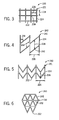
FIG. 6 is a schematic of an embodiment of an anode layer patterned as a grid with triangles to be coupled to a gasifier; -
FIG. 7 is a schematic of an embodiment of an anode layer patterned as a weave of metal ribbons to be coupled to a gasifier; -
FIG. 8 is a schematic of an embodiment of a perforated foil anode layer patterned with circles to be coupled to a gasifier; -
FIG. 9 is a schematic of an embodiment of a perforated foil anode layer patterned with chevrons to be coupled to a gasifier; and -
FIG. 10 is a schematic of a system that controls an electrical current to a patterned anode layer disposed in a gasifier. - One or more specific embodiments of the present invention will be described below. In an effort to provide a concise description of these embodiments, all features of an actual implementation may not be described in the specification. It should be appreciated that in the development of any such actual implementation, as in any engineering or design project, numerous implementation-specific decisions must be made to achieve the developers' specific goals, such as compliance with system-related and business-related constraints, which may vary from one implementation to another. Moreover, it should be appreciated that such a development effort might be complex and time consuming, but would nevertheless be a routine undertaking of design, fabrication, and manufacture for those of ordinary skill having the benefit of this disclosure.
- When introducing elements of various embodiments of the present invention, the articles "a," "an," "the," and "said" are intended to mean that there are one or more of the elements. The terms "comprising," "including," and "having" are intended to be inclusive and mean that there may be additional elements other than the listed elements.
- Corrosion may refer to an electrochemical oxidation of metals reacting with an oxidant, such as oxygen. Corroded metal components may be replaced or repaired because the metal oxides may not have the same properties as the original metal. The conditions in a gasification region of a gasification component, such as a gasifier or gas treatment unit of an IGCC power plant, may contribute to at least one type of corrosion. Aqueous electrochemical corrosion may result from an electrochemical reaction associated with differences in electrical potentials of two different, electrically connected metals in an aqueous medium. The two different metals may be referred to as an active metal and a noble metal. Ions of noble metals are more strongly bound to a surface of the noble metal than ions of active metals. In addition, the noble and active metals may be electrically connected by being in physical contact with one another. Furthermore, examples of aqueous media, also referred to generally as electrolytes, may include, but are not limited to, solutions of acids, bases, or salts, certain gases at high temperatures, molten salts, or combinations thereof. Specifically, hot gases in the gasification region of the gasification component may condense to form a liquid on the walls of the gasification component and on other equipment.
- During the electrochemical reaction of aqueous corrosion, ions from the active metal are released and flow through the aqueous medium to join with the noble metal. Concurrently, electrons flow from the active metal, or anode, to the noble metal, or cathode, through the electrical connection. By releasing its ions, the active metal may continue to corrode until it is completely consumed. In contrast, the noble metal may either not be affected or may corrode at a slower rate than the active metal. Examples of noble metals include, but are not limited to, silver, platinum, and gold. Furthermore, examples of active, or base, metals include, but are not limited to, iron, nickel, lead, and zinc.
- In certain gasifiers, aqueous corrosion may occur where two different metals are in contact with one another in the presence of a salt, such as ammonium chloride (NH4Cl), in the presence of water. The NH4Cl may be produced as a by-product in the gasifier and water may be introduced by injection of steam into the gasifier. In other gasifiers, two different metals may not be present, but aqueous corrosion can still occur according the following process. Certain metal surfaces of the gasifier may be passivated, which refers to a formation of a thin layer of metal oxide that acts as a barrier to further corrosion under conditions specific to the metal. Examples of metals that may undergo passivation include, but are not limited to, aluminum, stainless steel, titanium, or combinations thereof. An active-passive cell is created when salt deposits, such as NH4Cl, in the presence of water form in areas of the metal where the passive film is broken. An electrical potential develops between the large area of the passive film, which acts as the noble metal or cathode, and the small area of active, unpassivated metal, which acts as the anode. Thus, even gasifiers made from a single metal may be subject to aqueous corrosion.
- In particular embodiments discussed below, anodes may be used to help reduce aqueous corrosion or possibly other types of corrosion that may occur in gasification components. For example, sacrificial anode layers may be placed in electrical contact with metal surfaces to be protected from corrosion. Specifically, sacrificial anode layers are made from metals that are more electrochemically active than the metal surfaces of a shell of the gasifier. A hierarchy of metals, referred to as a galvanic series, may be used to determine whether a particular metal is more or less electrochemically active than another metal. More noble metals may be near one end of the galvanic series and more active metals may be near the other end of the galvanic series. Two metals are submerged in an electrolyte while electrically connected to determine the sequence of metals for the galvanic series. The less noble metal will experience galvanic corrosion. Moreover, the difference in nobility of the metals affects the rate of galvanic corrosion, which may be measured as a difference in voltage potential. Thus, two metals with a large difference in voltage potential may be farther apart in the galvanic series. In addition, the rate of galvanic corrosion may be affected by the electrolyte. Thus, the sequence of metals in the galvanic series may differ depending on the electrolyte.
- Using the appropriate galvanic series based on the conditions in the gasifier, one or more different metals for the sacrificial anode layer are selected from those metals that are more electrochemically active than the metal used for the gasifier shell. Thus, the sacrificial anode layer will preferentially corrode instead of the metal of the gasifier shell. By using more than one metal for the sacrificial anode layer, after a first electrochemically active metal is consumed, the gasifier may still be protected by a second metal, for example. Alternatively, the more electrochemically active metal may be located in areas of the gasifier that are more susceptible to corrosion. Examples of metals that may be used for the sacrificial anode layer include, but are not limited to, carbon steel, aluminum, mixed metal oxides, or combinations thereof. Mixed metal oxides may refer to sacrificial anode layers with a surface made from a mixture of platinum group metals covering a substrate made from titanium. The mixture of platinum group metals is electrically conductive and activates the titanium, such that it functions as a sacrificial anode. In addition, to provide sufficient driving force for the sacrificial anode layer to be preferentially corroded, the difference in the voltage potential between the two metals may be between approximately 0.1 to 1.5 volt, 0.2 to 1.0 volt, or 0.3 to 0.5 volt. In other words, the metal for the sacrificial anode layer may be approximately 10 percent, 50 percent, 500 percent, or 1,500 percent more electrochemically active than the metal for the gasifier shell. When properly selected, ions and electrons will flow under corrosive conditions from the sacrificial anode layer to the metal of the gasifier shell, which acts as the cathode, at a sufficient rate until the sacrificial anode layer is completely consumed. At that point, a new sacrificial anode layer is installed to continue to protect the gasifier shell from corrosion.
- In other embodiments, an impressed current system may be used to actively protect metal from corrosion. In contrast to the sacrificial anode layers discussed above, the anode layer of an impressed current system is not consumed or is consumed very slowly during protection of the gasifier shell. Instead, the anode layer is connected to an external electrical power source and a transformer rectifier, which creates a potential difference between the anode layer and the structure to be protected. The potential difference impresses, or transfers, electrons from the aqueous medium via chemical oxidation/reduction reactions at a surface of the anode layer to the surface of the gasifier shell. Hence, in a properly configured system, the anode layer is not consumed. Because the anode layer of the impressed current system is not consumed, the anode layer may be smaller than sacrificial anode layers. The addition of electrons, or electrical current, from the anode layer to the gasifier shell may reduce aqueous corrosion by helping to prevent the metal of the gasifier shell from releasing electrons and being corroded. However, if the flow of electrons from the anode layer is insufficient, corrosion of the gasifier shell may still occur. Alternatively, if the flow of electrons is too high, the gasifier shell may be damaged by hydrogen embrittlement. Under certain conditions, hydrogen ions present in the electrolyte may be reduced to hydrogen atoms at the cathode. The hydrogen atoms may permeate the granular structure of certain metals, such as high strength steels, causing hydrogen embrittlement. Thus, one method to determine that a proper flow of electrons is transferred from the anode layer is to install a reference electrode in the gasifier. The reference electrode may be used to monitor the electrical potential across the gasifier shell and the reference electrode and sends a signal to a controller to maintain the electrical potential across the reference electrode and the gasifier shell within an acceptable range. Reference electrodes may also be used with sacrificial anode layers to indicate when to replace the sacrificial anode layers.
- With either sacrificial anode layers or impressed current systems, several steps may be performed to determine specifications of a corrosion protection system. First, a suitable protection potential of the metal used for the gasifier shell during operation is determined. Laboratory testing using a protentiostat may be used to predict the required protection potential if it cannot be measured during actual operation. Next, a protection current for the gasifier shell is determined. The protection current is a function of a surface area of the structure to be protected, an electrolyte flow rate, an operating temperature range, and a geometry of the protected structure. In addition, a suitable anode coverage scheme and configuration is determined based on the geometry of the protected structure and an anode throwing power, which may refer to an ability of the anode to protect recessed or blind areas of the structure. Next, a suitable surface area of the anode is determined to obtain an anode current that is greater than the protection current. The surface area of the anode is a function of the anode surface area and the material selected for the anode. Finally, a mass of anode material is determined as a function of the protection current and a suitable service time. This last step may not apply to impressed current systems as the anode layer is not typically consumed. Knowing these specifications, the corrosion protection system may be configured to help reduce corrosion of the gasifier shell.
- Although described separately, both systems described above may be used simultaneously in certain embodiments of gasifiers. For example, if electrical current is unavailable for the impressed current system, the sacrificial anode layer may continue to protect the surface of the gasifier shell. Alternatively, if the sacrificial anode layer is completely consumed, the impressed current system may continue to help reduce corrosion. In other embodiments, the sacrificial anode layer or the impressed current system may be installed individually to reduce complexity and/or costs. Initially, using sacrificial anodes layers may be less costly and simpler than an impressed current system as no reference electrode, power source, transformer rectifier, and/or controller is used. However, the sacrificial anode layers are replaced on a regular basis as they are consumed, resulting in ongoing replacement costs and maintenance downtime.
- Both sacrificial anode layers and impressed current systems offer several advantages over other methods of corrosion protection. For example, such systems may be less costly than using expensive corrosion resistant alloys. In addition, such systems may enable operation of the gasifier at higher pressures and temperatures where efficiency is greater. Lower pressures and temperatures may reduce corrosion, but also reduce efficiency. Finally, such systems may enable lower quality and/or less expensive fuel to be combusted in the gasifier. Higher quality fuel may contain fewer corrosive gases, but may be more expensive than lower quality fuel.
- Turning now to the drawings,
FIG. 1 is a diagram of an embodiment of anIGCC system 100 that may produce and burn syngas. TheIGCC system 100 may include an embodiment of the gasification component with surfaces subject to corrosion that are protected by sacrificial anode layers and/or impressed current systems. In addition, other gas treatment or gas purifying components, carbon capture components, or any other components of theIGCC system 100 susceptible to corrosion may be protected by embodiments of sacrificial anode layers and/or impressed current systems. Other elements of theIGCC system 100 may include afuel source 102, which may be a solid or a liquid, that may be utilized as a source of energy for the IGCC system. Thefuel source 102 may include coal, petroleum coke, oil, biomass, wood-based materials, agricultural wastes, tars, coke oven gas and asphalt, or other carbon containing items. - The fuel of the
fuel source 102 may be passed to afeedstock preparation unit 104. Thefeedstock preparation unit 104 may, for example, resize or reshape thefuel source 102 by chopping, milling, shredding, pulverizing, briquetting, or palletizing thefuel source 102 to generate feedstock. Additionally, water, or other suitable liquids may be added to thefuel source 102 in thefeedstock preparation unit 104 to create slurry feedstock. In other embodiments, no liquid is added to the fuel source, thus yielding dry feedstock. In further embodiments, thefeedstock preparation unit 104 may be omitted if thefuel source 102 is a liquid. - The feedstock may be passed to a
gasifier 106 from thefeedstock preparation unit 104. Surfaces of the shell of thegasifier 106 in contact with a hot condensing gas, or condensing gasification product gas, as described below may be subject to corrosion and thus, may be protected by sacrificial anode layers and/or impressed current systems. Thegasifier 106 may convert the feedstock into a syngas, e.g., a combination of carbon monoxide (CO) and hydrogen. This conversion may be accomplished by subjecting the feedstock to a controlled amount of steam and oxygen at elevated pressures, e.g., from approximately 20 bar to 85 bar, and temperatures, e.g., approximately 700 degrees Celsius (C) to 1600 degrees C, depending on the type ofgasifier 106 utilized. The gasification process may include the feedstock undergoing a pyrolysis process, whereby the feedstock is heated. Temperatures inside thegasifier 106 may range from approximately 150 degrees C to 700 degrees C during the pyrolysis process, depending on thefuel source 102 utilized to generate the feedstock. The heating of the feedstock during the pyrolysis process may generate a solid (e.g., char) and residue gases (e.g., CO, hydrogen, and nitrogen). The char remaining from the feedstock from the pyrolysis process may only weigh up to approximately 30% of the weight of the original feedstock. - The volatiles generated during the pyrolysis process, also known as devolatilization, may be partially combusted by introducing oxygen to the
gasifier 106. The volatiles may react with the oxygen to form CO2 and CO in combustion reactions, which provide heat for the subsequent gasification reactions. The temperatures generated by the combustion reactions may range from approximately 700 degrees C to 1600 degrees C. Next, steam may be introduced into thegasifier 106 during a gasification step. The char may react with the CO2 and steam to produce CO and hydrogen at temperatures ranging from approximately 800 degrees C to 1100 degrees C. In essence, the gasifier utilizes steam and oxygen to allow some of the feedstock to be "burned" to produce CO and release energy, which drives a second reaction that converts further feedstock to hydrogen and additional CO2. - In this way, the
gasifier 106 manufactures a resultant gas. This resultant gas may include approximately 85% of CO and hydrogen in equal proportions, as well as CH4, HCl, HF, COS, NH3, HCN, and H2S (based on the sulfur content of the feedstock). This resultant gas may be termed untreated syngas, because it includes, for example, H2S. Thegasifier 106 may also generate waste, such asslag 108, which may be a wet ash material. Thisslag 108 may be removed from thegasifier 106 and disposed of, for example, as road base or as another building material. Agas purifier 110 may be utilized to clean the untreated syngas. In one embodiment, thegas purifier 110 may be a water gas shift reactor. Thegas purifier 110 may scrub the untreated syngas to remove the HCl, HF, COS, HCN, and H2S from the untreated syngas, which may include separation ofsulfur 111 in asulfur processor 112. Furthermore, thegas purifier 110 may separatesalts 113 from the untreated syngas via awater treatment unit 114 that may utilize water purification techniques to generateusable salts 113 from the untreated syngas. Subsequently, the gas from thegas purifier 110 may include treated syngas (e.g., thesulfur 111 has been removed from the syngas), with trace amounts of other chemicals, e.g., NH3 (ammonia) and CH4 (methane). - In some embodiments, a gas processor may be utilized to remove additional residual gas components, such as ammonia and methane, as well as methanol or any residual chemicals from the treated syngas. However, removal of residual gas components from the treated syngas is optional, because the treated syngas may be utilized as a fuel even when it includes the residual gas components, e.g., tail gas. At this point, the treated syngas may include approximately 3% CO, approximately 55% H2, and approximately 40% CO2 and is substantially stripped of H2S.
- In some embodiments, a
carbon capture system 116 may remove and process the carbonaceous gas (e.g., carbon dioxide that is approximately 80-100 or 90-100 percent pure by volume) included in the syngas. Thecarbon capture system 116 also may include a compressor, a purifier, a pipeline that supplies CO2 for sequestration or enhanced oil recovery, a CO2 storage tank, or any combination thereof. The captured carbon dioxide may be transferred to a carbon dioxide expander, which decreases the temperature of the carbon dioxide (e.g., approximately 5-100 degrees C, or about 20-30 degrees C), thus enabling the carbon dioxide to be used as a suitable cooling agent for the system. The cooled carbon dioxide (e.g., approximately 20-40 degrees C, or about 30 degrees C) may be circulated through the system to meet its refrigeration needs or expanded through subsequent stages for even lower temperatures. The treated syngas, which has undergone the removal of its sulfur containing components and a large fraction of its carbon dioxide, may be then transmitted to acombustor 120, e.g., a combustion chamber, of agas turbine engine 118 as combustible fuel. - The
IGCC system 100 may further include an air separation unit (ASU) 122. TheASU 122 may operate to separate air into component gases by, for example, distillation techniques. TheASU 122 may separate oxygen from the air supplied to it from asupplemental air compressor 123, and theASU 122 may transfer the separated oxygen to thegasifier 106. Additionally, theASU 122 may transmit separated nitrogen to a diluent nitrogen (DGAN)compressor 124. - The
DGAN compressor 124 may compress the nitrogen received from theASU 122 at least to pressure levels equal to those in thecombustor 120, so as not to interfere with the proper combustion of the syngas. Thus, once theDGAN compressor 124 has adequately compressed the nitrogen to a proper level, theDGAN compressor 124 may transmit the compressed nitrogen to thecombustor 120 of thegas turbine engine 118. The nitrogen may be used as a diluent to facilitate control of emissions, for example. - As described previously, the compressed nitrogen may be transmitted from the
DGAN compressor 124 to thecombustor 120 of thegas turbine engine 118. Thegas turbine engine 118 may include aturbine 130, adrive shaft 131, and acompressor 132, as well as thecombustor 120. Thecombustor 120 may receive fuel, such as syngas, which may be injected under pressure from fuel nozzles. This fuel may be mixed with compressed air as well as compressed nitrogen from theDGAN compressor 124, and combusted withincombustor 120. This combustion may create hot pressurized exhaust gases. - The
combustor 120 may direct the exhaust gases towards an exhaust outlet of theturbine 130. As the exhaust gases from thecombustor 120 pass through theturbine 130, the exhaust gases force turbine blades in theturbine 130 to rotate thedrive shaft 131 along an axis of thegas turbine engine 118. As illustrated, thedrive shaft 131 is connected to various components of thegas turbine engine 118, including thecompressor 132. - The
drive shaft 131 may connect theturbine 130 to thecompressor 132 to form a rotor. Thecompressor 132 may include blades coupled to thedrive shaft 131. Thus, rotation of turbine blades in theturbine 130 may cause thedrive shaft 131 connecting theturbine 130 to thecompressor 132 to rotate blades within thecompressor 132. This rotation of blades in thecompressor 132 causes thecompressor 132 to compress air received via an air intake in thecompressor 132. The compressed air may then be fed to thecombustor 120 and mixed with fuel and compressed nitrogen to allow for higher efficiency combustion. Thedrive shaft 131 may also be connected to load 134, which may be a stationary load, such as an electrical generator for producing electrical power, for example, in a power plant. Indeed, load 134 may be any suitable device that is powered by the rotational output of thegas turbine engine 118. - The
IGCC system 100 also may include asteam turbine engine 136 and a heat recovery steam generation (HRSG)system 138. Thesteam turbine engine 136 may drive asecond load 140. Thesecond load 140 may also be an electrical generator for generating electrical power. However, both the first 130 and second 140 loads may be other types of loads capable of being driven by thegas turbine engine 118 andsteam turbine engine 136. In addition, although thegas turbine engine 118 andsteam turbine engine 136 may driveseparate loads gas turbine engine 118 andsteam turbine engine 136 may also be utilized in tandem to drive a single load via a single shaft. The specific configuration of thesteam turbine engine 136, as well as thegas turbine engine 118, may be implementation-specific and may include any combination of sections. - The
system 100 may also include theHRSG 138. Heated exhaust gas from thegas turbine engine 118 may be transported into theHRSG 138 and used to heat water and produce steam used to power thesteam turbine engine 136. Exhaust from, for example, a low-pressure section of thesteam turbine engine 136 may be directed into acondenser 142. Thecondenser 142 may utilize acooling tower 128 to exchange heated water for chilled water. Thecooling tower 128 acts to provide cool water to thecondenser 142 to aid in condensing the steam transmitted to thecondenser 142 from thesteam turbine engine 136. Condensate from thecondenser 142 may, in turn, be directed into theHRSG 138. Again, exhaust from thegas turbine engine 118 may also be directed into theHRSG 138 to heat the water from thecondenser 142 and produce steam. - In combined cycle systems, such as the
IGCC system 100, hot exhaust may flow from thegas turbine engine 118 and pass to theHRSG 138, where it may be used to generate high-pressure, high-temperature steam. The steam produced by theHRSG 138 may then be passed through thesteam turbine engine 136 for power generation. In addition, the produced steam may also be supplied to any other processes where steam may be used, such as to thegasifier 106. Thegas turbine engine 118 generation cycle is often referred to as the "topping cycle," whereas thesteam turbine engine 136 generation cycle is often referred to as the "bottoming cycle." By combining these two cycles as illustrated inFIG. 1 , theIGCC system 100 may lead to greater efficiencies in both cycles. In particular, exhaust heat from the topping cycle may be captured and used to generate steam for use in the bottoming cycle. -
FIG. 2 is a cross-sectional side view of an embodiment of thegasifier 106 for use with theIGCC system 100 ofFIG. 1 with ananode layer 169. Thegasifier 106 may have an axial axis ordirection 150, a radial axis ordirection 152, and a circumferential axis ordirection 154. Thegasifier 106 includes anenclosure 156, also referred to as the shell, that functions as a housing or outer casing for thegasifier 106. Theenclosure 156 includes afirst end portion 158 and asecond end portion 160. Anintermediate portion 162 is defined by the section of theenclosure 156 that lies axially between thefirst end portion 158 and thesecond end portion 160. Thefirst end portion 158 and thesecond end portion 160 include a dome-shapedtop wall 164, and a triangular-shaped (e.g., conical shaped)bottom wall 166, respectively. A side wall 168 (e.g., annular side wall) parallel to theaxis 150 is disposed in theintermediate portion 162 between thetop wall 164 and thebottom wall 166. As thetop wall 164, thebottom wall 166, and theside wall 168 may all come in contact with condensing hot gas, surfaces of these walls may be protected by sacrificial anode layers and/or impressed current systems. - In the illustrated embodiment, the
anode layer 169 is coupled to theenclosure 156. As described above, theanode layer 169 may include a sacrificial anode layer, an anode layer for an impressed current system, or a combination thereof. In addition, theanode layer 169 is made from a different metal than theenclosure 156. Furthermore, theanode layer 169 may be configured as a layer rather than individual anode blocks because the electrolyte may exist as a thin layer covering the internal surface of theenclosure 156. The thin layer of electrolyte may hinder ion transport, and thus, the throwing power of the anode. Configuring theanode layer 169 as a layer distributes the throwing power over a large, uniform area, which may help overcome the hindered ion transport through the electrolyte layer. In addition, theanode layer 169 may be attached to the entire inside surface of theenclosure 156 of thegasifier 106 or portions thereof. For example, theanode layer 169 may be installed only on internal surfaces of theenclosure 156 that are most susceptible to corrosion. In addition, the thickness and/or materials selected for theanode layer 169 may be varied based on the location within theenclosure 156. Moreover, one ormore anode layers 169 may be coupled on top of each other to provide additional strength and/or durability to the anode structure. - Specific embodiments of the
anode layer 169 are discussed in detail below. Methods of attaching theanode layer 169 to theenclosure 156 may vary depending on the particular configuration of theanode layer 169. However, in all methods, theanode layer 169 is in electrical contact with the metal of theenclosure 156. For example, theanode layer 169 may be configured as a metal mesh, grid, or foil, which may be attached to theenclosure 156 by methods, such as, but not limited to, welding, bolting, or other suitable techniques for mechanically affixing two metal structures. Alternatively, theanode layer 169 may be a composite material. For example, a layer of an insulating matrix, such as, but not limited to, grout, ceramic or silicate matrices, or combinations thereof, may be applied to the surface of theenclosure 156. Theanode layer 169 is coupled to theenclosure 156 by pressing theanode layer 168 into the grout. A thickness of the layer of grout is the same as or less than a thickness of theanode layer 169 to enable theanode layer 169 to contact theenclosure 156 and be exposed to the corrosive gases. In a further example, theanode layer 169 may be formed by continuously adhering a patterned coating to theenclosure 156. Examples of coating methods include, but are not limited to, printing, spray coating, brushing, electrochemical deposition, dipping, photo etching, sputtering, or combinations thereof. Thus, by using methods, such as those described above, the throwing power of theanode layer 169 may be uniformly distributed across the protected surface of theenclosure 156. - The illustrated embodiment also includes a
thermal barrier 170 concentrically disposed inside theenclosure 156. Thethermal barrier 170, theanode layer 169, and theenclosure 156 form awall assembly 172 that separates anexterior 174 of thegasifier 106 from an interior 176 of thegasifier 106. Thus, theanode layer 169 is disposed between the shell of thegasifier 106 and thethermal barrier 170. The interior 176 includes agasification chamber 178 where pyrolysis, combustion, gasification, or a combination thereof, may occur as previously described with respect toFIG. 1 . Thewall assembly 172 is configured to block heat transfer and leakage of gaseous components from the interior 176 to the exterior 174 during gasification. Additionally, thethermal barrier 170 may be configured to maintain the surface temperature of theenclosure 156 within a desired temperature range. Accordingly, thethermal barrier 170 may include passive shielding, active cooling, or a combination thereof. For example, in embodiments where thethermal barrier 170 is a passive thermal shield, it may be made of a variety of refractory materials (e.g., bricks) capable of withstanding temperatures up to or greater than approximately 500 degrees C, 1000 degrees C, 1500 degrees C, or even 2000 degrees C. That is, thethermal barrier 170, or refractory insulating lining, may be made of any material that maintains its predetermined physical and chemical characteristics upon exposure to such high temperatures. Suitable refractory materials for use as thethermal barrier 170 may include ceramics (e.g., clay or minerals), metals (e.g., titanium, tungsten), cermets (i.e., ceramic and metal composites), or other refractory materials (e.g., silica, aluminum oxide). The refractory materials may be attached to theanode layer 169 using a refractory grout coating, for example. For further example, certain embodiments may employ an active thermal cooling system as a component of thethermal barrier 170. In such embodiments, cooling tubes may be used for temperature reduction purposes. That is, a coolant (e.g., chilled water) may be circulated through one or more tubes to lower the surface temperature of theenclosure 156. The cooling tubes may also be susceptible to corrosion and thus, may be protected by an extension of theanode layer 169 and/or with a separate anode layer. - In the embodiment illustrated in
FIG. 2 , aninjector 180 is disposed in thetop wall 164 of thefirst end portion 158 of theenclosure 156. Theinjector 180 is longitudinally offset from anoutlet 187 by adistance 188 and includes aninjection axis 190 that determines the general orientation of the flow originating from theinjector 180. Theinjector 180 may be configured to inject fuel, oxygen (e.g., air), or a mixture of fuel and oxygen into thegasification chamber 178. For instance, theinjector 180 may inject fuel in the form of carbonaceous material, such as coal, petroleum, or biomass. In fact, theinjector 180 may inject any material suitable for the production of syngas via gasification (e.g., organic materials, such as wood or plastic waste). For further example, theinjector 180 may inject a controlled amount of oxygen and/or steam either alone or in combination with a suitable fuel. - In the illustrated embodiment, the
injection axis 190 is parallel to theaxis 150 and perpendicular to theradial axis 152 of thegasifier 106. In other words, theinjection axis 190 is parallel to alongitudinal axis 186. Such a feature has the effect of directing a fluid flow emerging from theinjector 180 in a generally downward direction (e.g., downstream flow direction), as indicated byarrows 194, through thegasification chamber 178 during use. In certain embodiments, theinjection axis 190 may be directed away from thelongitudinal axis 186 by an angle between approximately 0 to 45, 0 to 30, 0 to 20, or 0 to 10 degrees. Furthermore, certain embodiments of theinjector 180 may provide a divergent spray, e.g., fluid flow originating from theinjector 180 may diverge outward toward theside walls 168 in a generally downward direction (e.g., downstream flow direction), as indicated byreference numeral 196. - In the illustrated embodiment of the
gasifier 106, the resultant syngas emerges from thegasifier 106 viaoutlet 187 along a path generally defined byoutlet axis 204. That is, the syngas exits thegasifier 106 via a location in thebottom wall 166 of thegasifier 106. However, it should be noted that the gasifier design disclosed herein may be used with a variety of other gasification systems wherein the outlet is not disposed in a bottom wall. For instance, the disclosed embodiments may be used in conjunction with entrained flow gasifiers. In such embodiments, the direction of flow through thegasification chamber 178 may be upward through thegasifier 106, i.e., in a direction oppositearrows 194. In these systems, the resultant syngas may exit an outlet located on or near thetop wall 164 of thegasifier 106, while the molten slag may exit through thebottom wall 166. For further example, the disclosed embodiments may be employed in fluidized bed gasifiers. Likewise, the outlet in such devices may be located near thetop wall 164 of thegasifier 106 since the direction of flow is generally upward. - Turning now to various patterns of anode layers,
FIG. 3 shows a schematic of an embodiment of ananode system 220 patterned as agrid 221, which includeshorizontal members 222 andvertical members 224 in a perpendicular arrangement. The horizontal andvertical members FIG. 3 , in other embodiments, the horizontal andvertical members vertical members points 230, which provide for electrical continuity throughout thesystem 220. Methods for making the interconnection points 230 include, but are not limited to, welding, bolting, or other suitable techniques for mechanically affixing two metal structures. Thevertical members 224 are spaced apart by afirst distance 226 and thehorizontal members 222 are spaced apart by asecond distance 228. In various embodiments, thedistances vertical members anode system 220 as agrid 221 may provide for a uniform throwing power for theanode layer 169. - In certain embodiments, the
anode system 220 may be configured as a sacrificial anode layer, which may be consumed during operation of thegasifier 106 as described above. This occurs because the metal used for theanode layer 169 is electrochemically more active than the metal used for thegasifier 106. Thus, theanode layer 169 preferentially corrodes to protect thegasifier 106. In other embodiments, an impressed current system may be used and theanode layer 169 provides electrons from the aqueous medium via oxidation/reduction reactions with the aqueous medium to help reduce corrosion of thegasifier 106 without being consumed itself. In addition, as described above, portions of theanode layer 169 may be electrically connected atpoints 230 to enable a single transformer rectifier to impress electrical current to all the connected portions of theanode layer 169. For example, a negative pole of the transformer rectifier may be connected to only one portion of thegrid 221 ofsystem 220. A positive pole of the transformer rectifier for the impressed current system may be connected to the surface of theenclosure 156 of thegasifier 106. Thus, electrons may flow from the aqueous medium at the surface of theanode layer 169, through the electrolyte, and to thegasifier 106. -
FIG. 4 is a schematic of an embodiment of ananode system 240 patterned as agrid 241 withnon-perpendicular cross-members 242. Elements inFIG. 4 in common with those shown inFIG. 3 are labeled with the same references numerals. In the illustrated embodiment, thenon-perpendicular cross-members 242 provide a different method of interconnecting and supporting thevertical members 224. Specifically, theangled cross-members 242 are similar to thehorizontal members 222 ofFIG. 3 , but are non-perpendicular to thevertical members 224. In other words, anangle 244 between the cross-members 242 and thevertical members 224 is either greater than or less than approximately 90 degrees. Other aspects of thesystem 240 are similar to those of thesystem 220 ofFIG. 3 . -
FIG. 5 is a schematic of an embodiment of ananode system 250 patterned as agrid 251 withchevrons 252 or V-shaped members. Elements inFIG. 5 in common with those shown inFIG. 3 are labeled with the same references numerals. In the illustrated embodiment, thechevrons 252 interconnect and support thevertical members 224. Such a configuration of thesystem 250 may help direct any condensed liquids away from the walls of theenclosure 156 and toward theoutlet 187 of thegasifier 106 as shown inFIG. 2 . Reduced exposure to condensed liquids may help diminish the amount of corrosion of the walls of theenclosure 156. -
FIG. 6 shows a schematic of an embodiment of ananode system 260 patterned as agrid 261 withtriangles 262. Elements inFIG. 6 in common with those shown inFIG. 3 are labeled with the same references numerals. Thetriangles 262 in the illustrated embodiment are formed from alternatingangled cross-members 242. As with previous systems, thegrid 261 may provide for a more evenly dispersed throwing power for thesystem 260. Other aspects of thesystem 260 are similar to those of systems discussed above. -
FIG. 7 shows a schematic of an embodiment of ananode system 270 patterned as a weave of metal ribbons, which includeshorizontal ribbons 272 andvertical ribbons 274 in a perpendicular arrangement. Alternatively, theribbons FIG. 7 in common with those shown inFIG. 3 are labeled with the same references numerals. The horizontal andvertical ribbons FIG. 7 , in other embodiments, the horizontal andvertical ribbons vertical ribbons points 230, which provide for electrical continuity throughout thesystem 270. Methods for making the interconnection points 230 include, but are not limited to, welding, bolting, or other suitable techniques for mechanically affixing two metal structures. Thevertical ribbons 274 are spaced apart by adistance 226 and thehorizontal ribbons 272 are spaced apart by adistance 228. In various embodiments, thedistances vertical ribbons anode system 270 as a weave of ribbons may provide for a uniform throwing power for theanode layer 169. -
FIG. 8 shows a schematic of an embodiment of ananode system 280 with afoil 282 patterned with circle-shapedperforations 284, which are punched all the way through thefoil 282. Thefoil 282 may be easier to handle or install than the grids described above and may provide for a uniform throwing power for theanode layer 169. In addition, providing circle-shapedperforations 284 may reduce the amount offoil 282 used to cover the surface of theenclosure 156. Shapes other than circles may be used theperforations 284, such as, but not limited to, ovals, triangles, squares, rectangles, diamonds, polygons, and irregular shapes. Although shown in rows and columns, the circle-shapedperforations 284 may be arranged in other patterns or in irregular patterns in further embodiments. For example, the circle-shapedperforations 284 may be arranged in a circular pattern. In addition, ahorizontal distance 286 and avertical distance 288 may separate the circle-shapedperforations 284. The horizontal andvertical distances foil 282 has athickness 290, which may be between approximately 0.01 to 5 mm, 0.03 to 1 mm, or 0.05 to 0.5 mm. Thespecific thickness 290 selected for a particular application may depend on the mass of anode material determined using the method described above. -
FIG. 9 shows a schematic of an embodiment of ananode system 300 with afoil 282 patterned with chevron-shapedperforations 302, which are punched all the way through thefoil 282. Elements inFIG. 9 in common with those shown inFIG. 8 are labeled with the same references numerals. Such a configuration of the chevron-shapedperforations 302 may help direct any condensed liquids away from the walls of theenclosure 156 and toward theoutlet 187 of thegasifier 106 as shown inFIG. 2 . Reduced exposure to condensed liquids may help diminish the amount of corrosion of the walls of theenclosure 156. Other aspects of thesystem 300 are similar to those ofsystem 280 shown inFIG. 8 . -
FIG. 10 shows a schematic of an embodiment of asystem 310 that includes a controller to adjust electrical current to theanode layer 169. In the illustrated embodiment of the impressed current system, apower source 312 provides a relatively constant source of electric current, such as alternating current (AC), to atransformer rectifier 314. For example, thepower source 312 may provide high voltage 3-phase AC to thetransformer rectifier 314, which may "step down" the voltage to a lower voltage and convert the AC to direct current (DC). By connecting the positive terminal of thetransformer rectifier 314 to theanode layer 169 atfirst connection 316 and connecting the negative terminal to thewall 168 of thegasifier 106 atsecond connection 318, thetransformer rectifier 314 provides a potential difference across theanode layer 169 and thegasifier 106. Connection of thegasifier 106 and theanode layer 169 via electrical contact and ionic contact in the aqueous medium completes the electrochemical circuit. Thus, electrons flow from the aqueous medium at the surface of theanode layer 169, through the electrolyte, and to thegasifier 106. However, the electrochemical current is said to flow in the opposite direction according to normal convention. - In addition, a
reference electrode 320 may be connected to thetransformer rectifier 314 ofsystem 310. Thereference electrode 320 may represent a fixed potential against which the measured potential of thegasifier 106 may be compared. In addition, thetransformer rectifier 314 may act as a controller to maintain the proper protection potential across thereference electrode 320 and thegasifier 106. The protection potential may be determined based on laboratory testing or actual operating measurements as described above. For example, in certain embodiments, thereference electrode 320 may indicate via feedback to the transformer rectifier 314 (or controller) that the measured potential across thereference electrode 320 and thegasifier 106 is less than the proper protection potential. Thetransformer rectifier 314 may then increase the electrical potential difference between theanode layer 169 and thegasifier 106, such that the current increases from theanode layer 169 to thegasifier 106. Thus, by using thereference electrode 320 and thetransformer rectifier 314, thesystem 310 may continually adjust to respond to changing conditions and help reduce corrosion of thegasifier 106. In addition, although thesystem 310 represents an impressed current system, sacrificial anodes may be coupled to thegasifier 106 to serve as a backup method of corrosion protection as described above. - This written description uses examples to disclose the invention, including the best mode, and also to enable any person skilled in the art to practice the invention, including making and using any devices or systems and performing any incorporated methods. The patentable scope of the invention is defined by the claims, and may include other examples that occur to those skilled in the art. Such other examples are intended to be within the scope of the claims if they have structural elements that do not differ from the literal language of the claims, or if they include equivalent structural elements with insubstantial differences from the literal language of the claims.
- For completeness, various aspects of the invention are now set out in the following numbered clauses:
- 1. A system, comprising:
- a gasifier comprising a shell made of a first material exposed to a gasification region inside the gasifier; and
- a patterned anode layer coupled to the shell inside the gasifier, wherein the patterned anode layer is made of a second material, and the patterned anode layer is configured to protect the shell from corrosion by condensing hot gas in the gasification region.
- 2. The system of clause 1, wherein the patterned anode layer is configured to protect the shell from aqueous electrochemical corrosion.
- 3. The system of clause 1, comprising a refractory insulating lining disposed inside the shell, wherein the patterned anode layer is disposed between the shell and the refractory insulating lining.
- 4. The system of clause 1, wherein the patterned anode layer comprises a composite material having a metallic anode pattern disposed in an insulating matrix.
- 5. The system of clause 1, wherein the patterned anode layer comprises a metallic wire mesh coupled to the shell.
- 6. The system of clause 1, wherein the patterned anode layer comprises a patterned coating continuously adhered to the shell.
- 7. The system of clause 1, comprising a power source that supplies power to a transformer rectifier coupled to the patterned anode layer, wherein the transformer rectifier is configured to impress a current through the patterned anode layer to actively protect the first material from corrosion by the condensing hot gas.
- 8. The system of clause 7, comprising a reference electrode and a controller configured to adjust the current to the patterned anode layer in response to feedback from the reference electrode.
- 9. The system of clause 1, wherein the second material is electrochemically more active than the first material, and the second material is configured to preferentially corrode to protect the first material from corrosion by the condensing hot gas.
- 10. The system of clause 1, wherein the patterned anode layer comprises a third material that is electrochemically more active than the first material and the second material.
- 11. A system, comprising:
- a gasification component comprising a first material exposed to a flow of a condensing corrosive gas; and
- an anode layer comprising a second material coupled to the first material, wherein the anode layer is configured to protect the first material from corrosion by the condensing corrosive gas.
- 12. The system of clause 11, comprising a power source that supplies power to a transformer rectifier coupled to the anode layer, wherein the transformer rectifier is configured to impress a current through the anode layer to actively protect the first material from corrosion by the condensing corrosive gas.
- 13. The system of clause 11, wherein the anode layer is a sacrificial anode layer.
- 14. The system of clause 11, wherein the anode layer comprises a pattern of a plurality of anode portions.
- 15. The system of clause 11, wherein the anode layer comprises a third material that is different from the first and second materials.
- 16. The system of clause 11, wherein the gasification component comprises an integrated gasification combined cycle (IGCC) component.
- 17. The system of clause 16, wherein the IGCC component comprises a gasifier, a gas treatment unit, or a combination thereof.
- 18. A system, comprising:
- an active anode layer configured to protect a surface of a gasification component from corrosion by a gasification product gas;
- a reference electrode in contact with the gasification product gas; and
- a controller configured to adjust a current to the active anode layer in response to feedback from the reference electrode.
- 19. The system of clause 18, wherein the gasification component comprises an integrated gasification combined cycle (IGCC) component.
- 20. The system of clause 18, wherein the feedback from the reference electrode is indicative of an electrical potential difference across the reference electrode and the gasification component.
Claims (10)
- A system, comprising:a gasifier (106) comprising a shell (156) made of a first material exposed to a gasification region inside the gasifier (106); anda patterned anode layer (169) coupled to the shell (156) inside the gasifier (106), wherein the patterned anode layer (169) is made of a second material, and the patterned anode layer (169) is configured to protect the shell (156) from corrosion by condensing hot gas in the gasification region.
- The system of claim 1, wherein the patterned anode layer (169) is configured to protect the shell (156) from aqueous electrochemical corrosion.
- The system of claim 1 or 2, comprising a refractory insulating lining (170) disposed inside the shell (156), wherein the patterned anode layer (169) is disposed between the shell (156) and the refractory insulating lining (170).
- The system of any of the preceding claims, wherein the patterned anode layer (169) comprises a composite material having a metallic anode pattern disposed in an insulating matrix.
- The system of any of the preceding claims, wherein the patterned anode layer (169) comprises a metallic wire mesh coupled to the shell (156).
- The system of any of the preceding claims, wherein the patterned anode layer (169) comprises a patterned coating continuously adhered to the shell (156).
- The system of any of the preceding claims, comprising a power source (312) that supplies power to a transformer rectifier (314) coupled to the patterned anode layer (169), wherein the transformer rectifier (314) is configured to impress a current through the patterned anode layer (169) to actively protect the first material from corrosion by the condensing hot gas.
- The system of claim 7, comprising a reference electrode (320) and a controller (314) configured to adjust the current to the patterned anode layer (169) in response to feedback from the reference electrode (320).
- The system of any of the preceding claims, wherein the second material is electrochemically more active than the first material, and the second material is configured to preferentially corrode to protect the first material from corrosion by the condensing hot gas.
- The system of any of the preceding claims, wherein the patterned anode layer (169) comprises a third material that is electrochemically more active than the first material and the second material.
Applications Claiming Priority (1)
| Application Number | Priority Date | Filing Date | Title |
|---|---|---|---|
| US12/785,302 US8372251B2 (en) | 2010-05-21 | 2010-05-21 | System for protecting gasifier surfaces from corrosion |
Publications (3)
| Publication Number | Publication Date |
|---|---|
| EP2404984A2 true EP2404984A2 (en) | 2012-01-11 |
| EP2404984A3 EP2404984A3 (en) | 2012-05-30 |
| EP2404984B1 EP2404984B1 (en) | 2015-07-08 |
Family
ID=44786941
Family Applications (1)
| Application Number | Title | Priority Date | Filing Date |
|---|---|---|---|
| EP11166934.7A Active EP2404984B1 (en) | 2010-05-21 | 2011-05-20 | System for protecting gasifier surfaces from corrosion |
Country Status (4)
| Country | Link |
|---|---|
| US (1) | US8372251B2 (en) |
| EP (1) | EP2404984B1 (en) |
| JP (1) | JP5802431B2 (en) |
| CN (1) | CN102250648B (en) |
Families Citing this family (73)
| Publication number | Priority date | Publication date | Assignee | Title |
|---|---|---|---|---|
| MY153097A (en) | 2008-03-28 | 2014-12-31 | Exxonmobil Upstream Res Co | Low emission power generation and hydrocarbon recovery systems and methods |
| MY156350A (en) | 2008-03-28 | 2016-02-15 | Exxonmobil Upstream Res Co | Low emission power generation and hydrocarbon recovery systems and methods |
| BRPI0920139A2 (en) | 2008-10-14 | 2015-12-22 | Exxonmobil Upstream Res Co | combustion system, combustion control method, and combustion system. |
| BRPI1010940B1 (en) * | 2009-05-22 | 2019-09-17 | Sasol Technology (Proprietary) Limited | PROCESS FOR CO-PRODUCTION OF SYNTHESIS AND ENERGY GAS |
| CN102597418A (en) | 2009-11-12 | 2012-07-18 | 埃克森美孚上游研究公司 | Low emission power generation and hydrocarbon recovery systems and methods |
| US8268134B2 (en) * | 2010-05-21 | 2012-09-18 | General Electric Company | System for protecting turbine engine surfaces from corrosion |
| US8372251B2 (en) * | 2010-05-21 | 2013-02-12 | General Electric Company | System for protecting gasifier surfaces from corrosion |
| AU2011271636B2 (en) | 2010-07-02 | 2016-03-17 | Exxonmobil Upstream Research Company | Low emission power generation systems and methods |
| MY160832A (en) | 2010-07-02 | 2017-03-31 | Exxonmobil Upstream Res Co | Stoichiometric combustion with exhaust gas recirculation and direct contact cooler |
| EA029301B1 (en) | 2010-07-02 | 2018-03-30 | Эксонмобил Апстрим Рисерч Компани | Integrated systems for corecovery (embodiments) and method of generating power |
| CA2801494C (en) | 2010-07-02 | 2018-04-17 | Exxonmobil Upstream Research Company | Stoichiometric combustion of enriched air with exhaust gas recirculation |
| TWI563166B (en) | 2011-03-22 | 2016-12-21 | Exxonmobil Upstream Res Co | Integrated generation systems and methods for generating power |
| TWI564474B (en) | 2011-03-22 | 2017-01-01 | 艾克頌美孚上游研究公司 | Integrated systems for controlling stoichiometric combustion in turbine systems and methods of generating power using the same |
| TWI563165B (en) | 2011-03-22 | 2016-12-21 | Exxonmobil Upstream Res Co | Power generation system and method for generating power |
| TWI593872B (en) | 2011-03-22 | 2017-08-01 | 艾克頌美孚上游研究公司 | Integrated system and method of generating power |
| CN104428490B (en) | 2011-12-20 | 2018-06-05 | 埃克森美孚上游研究公司 | The coal bed methane production of raising |
| WO2013091685A1 (en) | 2011-12-21 | 2013-06-27 | Leibniz-Institut Für Neue Materialien Gemeinnützige Gmbh | Highly structured composite material and process for the manufacture of protective coatings for corroding substrates |
| WO2013091686A1 (en) * | 2011-12-21 | 2013-06-27 | Tenaris Connections Limited | Corrosion resistant equipment for oil and/or gas applications |
| US9353682B2 (en) | 2012-04-12 | 2016-05-31 | General Electric Company | Methods, systems and apparatus relating to combustion turbine power plants with exhaust gas recirculation |
| US9784185B2 (en) | 2012-04-26 | 2017-10-10 | General Electric Company | System and method for cooling a gas turbine with an exhaust gas provided by the gas turbine |
| US10273880B2 (en) | 2012-04-26 | 2019-04-30 | General Electric Company | System and method of recirculating exhaust gas for use in a plurality of flow paths in a gas turbine engine |
| US9611756B2 (en) | 2012-11-02 | 2017-04-04 | General Electric Company | System and method for protecting components in a gas turbine engine with exhaust gas recirculation |
| US9599070B2 (en) | 2012-11-02 | 2017-03-21 | General Electric Company | System and method for oxidant compression in a stoichiometric exhaust gas recirculation gas turbine system |
| US9869279B2 (en) | 2012-11-02 | 2018-01-16 | General Electric Company | System and method for a multi-wall turbine combustor |
| US9708977B2 (en) | 2012-12-28 | 2017-07-18 | General Electric Company | System and method for reheat in gas turbine with exhaust gas recirculation |
| US9631815B2 (en) | 2012-12-28 | 2017-04-25 | General Electric Company | System and method for a turbine combustor |
| US10107495B2 (en) | 2012-11-02 | 2018-10-23 | General Electric Company | Gas turbine combustor control system for stoichiometric combustion in the presence of a diluent |
| US9803865B2 (en) | 2012-12-28 | 2017-10-31 | General Electric Company | System and method for a turbine combustor |
| US10215412B2 (en) | 2012-11-02 | 2019-02-26 | General Electric Company | System and method for load control with diffusion combustion in a stoichiometric exhaust gas recirculation gas turbine system |
| US9574496B2 (en) | 2012-12-28 | 2017-02-21 | General Electric Company | System and method for a turbine combustor |
| US10100741B2 (en) | 2012-11-02 | 2018-10-16 | General Electric Company | System and method for diffusion combustion with oxidant-diluent mixing in a stoichiometric exhaust gas recirculation gas turbine system |
| US10208677B2 (en) | 2012-12-31 | 2019-02-19 | General Electric Company | Gas turbine load control system |
| US9581081B2 (en) | 2013-01-13 | 2017-02-28 | General Electric Company | System and method for protecting components in a gas turbine engine with exhaust gas recirculation |
| US9512759B2 (en) | 2013-02-06 | 2016-12-06 | General Electric Company | System and method for catalyst heat utilization for gas turbine with exhaust gas recirculation |
| US9938861B2 (en) | 2013-02-21 | 2018-04-10 | Exxonmobil Upstream Research Company | Fuel combusting method |
| TW201502356A (en) | 2013-02-21 | 2015-01-16 | Exxonmobil Upstream Res Co | Reducing oxygen in a gas turbine exhaust |
| RU2637609C2 (en) | 2013-02-28 | 2017-12-05 | Эксонмобил Апстрим Рисерч Компани | System and method for turbine combustion chamber |
| US9618261B2 (en) | 2013-03-08 | 2017-04-11 | Exxonmobil Upstream Research Company | Power generation and LNG production |
| WO2014137648A1 (en) | 2013-03-08 | 2014-09-12 | Exxonmobil Upstream Research Company | Power generation and methane recovery from methane hydrates |
| TW201500635A (en) | 2013-03-08 | 2015-01-01 | Exxonmobil Upstream Res Co | Processing exhaust for use in enhanced oil recovery |
| US20140250945A1 (en) | 2013-03-08 | 2014-09-11 | Richard A. Huntington | Carbon Dioxide Recovery |
| US9617914B2 (en) | 2013-06-28 | 2017-04-11 | General Electric Company | Systems and methods for monitoring gas turbine systems having exhaust gas recirculation |
| TWI654368B (en) | 2013-06-28 | 2019-03-21 | 美商艾克頌美孚上游研究公司 | System, method and media for controlling exhaust gas flow in an exhaust gas recirculation gas turbine system |
| US9835089B2 (en) | 2013-06-28 | 2017-12-05 | General Electric Company | System and method for a fuel nozzle |
| US9631542B2 (en) | 2013-06-28 | 2017-04-25 | General Electric Company | System and method for exhausting combustion gases from gas turbine engines |
| US9587510B2 (en) | 2013-07-30 | 2017-03-07 | General Electric Company | System and method for a gas turbine engine sensor |
| US9903588B2 (en) | 2013-07-30 | 2018-02-27 | General Electric Company | System and method for barrier in passage of combustor of gas turbine engine with exhaust gas recirculation |
| US9951658B2 (en) | 2013-07-31 | 2018-04-24 | General Electric Company | System and method for an oxidant heating system |
| US9752458B2 (en) | 2013-12-04 | 2017-09-05 | General Electric Company | System and method for a gas turbine engine |
| US10030588B2 (en) | 2013-12-04 | 2018-07-24 | General Electric Company | Gas turbine combustor diagnostic system and method |
| US10227920B2 (en) | 2014-01-15 | 2019-03-12 | General Electric Company | Gas turbine oxidant separation system |
| US9863267B2 (en) | 2014-01-21 | 2018-01-09 | General Electric Company | System and method of control for a gas turbine engine |
| US9915200B2 (en) | 2014-01-21 | 2018-03-13 | General Electric Company | System and method for controlling the combustion process in a gas turbine operating with exhaust gas recirculation |
| US10079564B2 (en) | 2014-01-27 | 2018-09-18 | General Electric Company | System and method for a stoichiometric exhaust gas recirculation gas turbine system |
| US9005536B1 (en) * | 2014-05-01 | 2015-04-14 | ARK Power Dynamics, LLC | Apparatus and method for conversion of solid waste into synthetic oil, gas, and fertilizer |
| US10047633B2 (en) | 2014-05-16 | 2018-08-14 | General Electric Company | Bearing housing |
| US9885290B2 (en) | 2014-06-30 | 2018-02-06 | General Electric Company | Erosion suppression system and method in an exhaust gas recirculation gas turbine system |
| US10060359B2 (en) | 2014-06-30 | 2018-08-28 | General Electric Company | Method and system for combustion control for gas turbine system with exhaust gas recirculation |
| US10655542B2 (en) | 2014-06-30 | 2020-05-19 | General Electric Company | Method and system for startup of gas turbine system drive trains with exhaust gas recirculation |
| US9869247B2 (en) | 2014-12-31 | 2018-01-16 | General Electric Company | Systems and methods of estimating a combustion equivalence ratio in a gas turbine with exhaust gas recirculation |
| US9819292B2 (en) | 2014-12-31 | 2017-11-14 | General Electric Company | Systems and methods to respond to grid overfrequency events for a stoichiometric exhaust recirculation gas turbine |
| US10788212B2 (en) | 2015-01-12 | 2020-09-29 | General Electric Company | System and method for an oxidant passageway in a gas turbine system with exhaust gas recirculation |
| US10253690B2 (en) | 2015-02-04 | 2019-04-09 | General Electric Company | Turbine system with exhaust gas recirculation, separation and extraction |
| US10316746B2 (en) | 2015-02-04 | 2019-06-11 | General Electric Company | Turbine system with exhaust gas recirculation, separation and extraction |
| US10094566B2 (en) | 2015-02-04 | 2018-10-09 | General Electric Company | Systems and methods for high volumetric oxidant flow in gas turbine engine with exhaust gas recirculation |
| US10267270B2 (en) | 2015-02-06 | 2019-04-23 | General Electric Company | Systems and methods for carbon black production with a gas turbine engine having exhaust gas recirculation |
| US10145269B2 (en) | 2015-03-04 | 2018-12-04 | General Electric Company | System and method for cooling discharge flow |
| US10480792B2 (en) | 2015-03-06 | 2019-11-19 | General Electric Company | Fuel staging in a gas turbine engine |
| US10273585B2 (en) | 2015-06-10 | 2019-04-30 | Westmill Industries Ltd. | Cathodic protection for wood veneer dryers and method for reducing corrosion of wood veneer dryers |
| IT201600111822A1 (en) * | 2016-11-07 | 2018-05-07 | Reset S R L | WOOD BIOMASS COGENERATION PLANT FOR CONTINUOUS PRODUCTION OF HEAT AND ELECTRICITY. |
| CN112996932B (en) * | 2018-07-11 | 2022-06-21 | 乌斯季卡面诺戈尔斯克钛和镁种植股份有限公司 | Device for chlorinating titanium-containing raw material in chloride salt melt |
| US10637090B2 (en) * | 2018-09-27 | 2020-04-28 | United States Of America As Represented By Secretary Of The Navy | Self-contained and scalable microbial fuel cell array with grid-based anode and bottle brush cathode power sensors underwater |
| CN111495679B (en) * | 2020-04-28 | 2021-12-07 | 南兴装备股份有限公司 | Method for monitoring leakage condition of gluing mechanism of edge bonding machine |
Family Cites Families (19)
| Publication number | Priority date | Publication date | Assignee | Title |
|---|---|---|---|---|
| US3216916A (en) | 1962-11-13 | 1965-11-09 | Continental Oil Co | Anodic passivation of wetted wall vessels |
| US3379629A (en) | 1965-02-08 | 1968-04-23 | Continental Oil Co | Method and apparatus for automatically controlling corrosion of process vessels |
| CA1184440A (en) * | 1982-07-29 | 1985-03-26 | Texaco Development Corporation | High temperature furnace |
| US5411646A (en) * | 1993-05-03 | 1995-05-02 | Corrpro Companies, Inc. | Cathodic protection anode and systems |
| WO1999047874A1 (en) | 1998-03-19 | 1999-09-23 | Siemens Aktiengesellschaft | Wall segment for a combustion chamber and combustion chamber |
| JP2001064788A (en) * | 1999-08-26 | 2001-03-13 | Sumikou Boshoku Kk | Corrosion-protective method of metal surface in contact with flowing water of water film |
| DE19957696C1 (en) | 1999-11-30 | 2001-05-03 | Krc Umwelttechnik Gmbh | Apparatus for gasifying carbon-containing fuels, residual materials and waste comprises a fly stream reactor with cooling channels formed by bars which are in contact with a refractory protective layer and a pressure shell |
| BR0110397A (en) * | 2000-05-05 | 2003-02-25 | Dow Global Technologies Inc | Refractory Pressure Vessel |
| IT1315637B1 (en) * | 2000-06-08 | 2003-03-14 | Thermowatt Spa | DEVICE FOR THE ANTI-CORROSION PROTECTION OF METAL TANKS IN PARTICULAR WATER HEATERS. |
| SE0203605D0 (en) | 2002-12-04 | 2002-12-04 | Chemrec Ab | Device for the gasification or oxidization of an energy containing fuel |
| CN2619938Y (en) * | 2003-05-12 | 2004-06-09 | 西北化工研究院 | Semi-water cooled wall type multiple pulp gasifying furnace |
| GB0409521D0 (en) | 2004-04-29 | 2004-06-02 | Fosroc International Ltd | Sacrificial anode assembly |
| CN2804123Y (en) * | 2005-05-21 | 2006-08-09 | 过梦飞 | Net anode with external adding current cathode protector |
| JP2006328505A (en) * | 2005-05-27 | 2006-12-07 | Pacific Consultants Co Ltd | Electric corrosion protection device |
| US7230347B2 (en) * | 2005-10-14 | 2007-06-12 | General Electric Company | Corrosion protection for wind turbine units in a marine environment |
| US7585397B2 (en) * | 2006-04-30 | 2009-09-08 | Farwest Corrosion Control Company | Automatic potential control cathodic protection system for storage tanks |
| US9228458B2 (en) * | 2010-02-19 | 2016-01-05 | Ford Global Technologies, Llc | Valve seat insert |
| US8268134B2 (en) * | 2010-05-21 | 2012-09-18 | General Electric Company | System for protecting turbine engine surfaces from corrosion |
| US8372251B2 (en) * | 2010-05-21 | 2013-02-12 | General Electric Company | System for protecting gasifier surfaces from corrosion |
-
2010
- 2010-05-21 US US12/785,302 patent/US8372251B2/en active Active
-
2011
- 2011-05-18 JP JP2011110891A patent/JP5802431B2/en active Active
- 2011-05-20 EP EP11166934.7A patent/EP2404984B1/en active Active
- 2011-05-20 CN CN201110130863.7A patent/CN102250648B/en not_active Expired - Fee Related
Non-Patent Citations (1)
| Title |
|---|
| None |
Also Published As
| Publication number | Publication date |
|---|---|
| US8372251B2 (en) | 2013-02-12 |
| EP2404984B1 (en) | 2015-07-08 |
| CN102250648A (en) | 2011-11-23 |
| CN102250648B (en) | 2015-03-25 |
| JP5802431B2 (en) | 2015-10-28 |
| JP2011246707A (en) | 2011-12-08 |
| EP2404984A3 (en) | 2012-05-30 |
| US20110284368A1 (en) | 2011-11-24 |
Similar Documents
| Publication | Publication Date | Title |
|---|---|---|
| US8372251B2 (en) | System for protecting gasifier surfaces from corrosion | |
| US8268134B2 (en) | System for protecting turbine engine surfaces from corrosion | |
| EP2799520B1 (en) | Biomass gasification island process under high temperature and atmospheric pressure | |
| US8597385B2 (en) | Method and apparatus for shielding cooling tubes in a radiant syngas cooler | |
| CN118715173A (en) | Hydrogen production system and method | |
| US8151716B2 (en) | Feed injector cooling apparatus and method of assembly | |
| US20210207529A1 (en) | Gasifier wall, integrated gasification combined cycle power generation equipment comprising same, and method for producing gasifier wall | |
| JP6642924B2 (en) | Hydrogen station system | |
| CN105008801B (en) | Feed Syringe Tip Cap | |
| CN106537035A (en) | Combustion of lithium at different temperatures and pressures and with gas surpluses using porous tubes as burners | |
| JP2007270212A (en) | Hydrogen production device and fuel cell power-generating apparatus | |
| JP2010184973A (en) | Fuel gas refiner, power generation system, and fuel synthesizing system | |
| JP2005232523A (en) | Hydrogen production system in nuclear power generation plant | |
| Agboola et al. | Short overview on the mitigation of corrosion in coal gasification plant | |
| Kacprzak | Analysis of the current state and development of direct carbon fuel cells with an alkaline electrolyte | |
| Hans Pastoors | Materials behavior in the NUON power IGCC plant in Buggenum | |
| Lynch | Operating Experience at the Wabash River Coal Gasification Repowering Project | |
| JP2014149185A (en) | Wastage measuring apparatus and wastage measuring method | |
| Nangia | Materials for coal conversion and use. Volume III. Materials of construction for advanced power systems | |
| Li | Economics, business, marketing, policy | |
| JP2019138519A (en) | Furnace wall structure of wet furnace and wet furnace |
Legal Events
| Date | Code | Title | Description |
|---|---|---|---|
| AK | Designated contracting states |
Kind code of ref document: A2 Designated state(s): AL AT BE BG CH CY CZ DE DK EE ES FI FR GB GR HR HU IE IS IT LI LT LU LV MC MK MT NL NO PL PT RO RS SE SI SK SM TR |
|
| AX | Request for extension of the european patent |
Extension state: BA ME |
|
| PUAI | Public reference made under article 153(3) epc to a published international application that has entered the european phase |
Free format text: ORIGINAL CODE: 0009012 |
|
| PUAL | Search report despatched |
Free format text: ORIGINAL CODE: 0009013 |
|
| AK | Designated contracting states |
Kind code of ref document: A3 Designated state(s): AL AT BE BG CH CY CZ DE DK EE ES FI FR GB GR HR HU IE IS IT LI LT LU LV MC MK MT NL NO PL PT RO RS SE SI SK SM TR |
|
| AX | Request for extension of the european patent |
Extension state: BA ME |
|
| RIC1 | Information provided on ipc code assigned before grant |
Ipc: C10J 3/74 20060101ALI20120420BHEP Ipc: B01J 19/02 20060101ALI20120420BHEP Ipc: C23F 13/00 20060101ALI20120420BHEP Ipc: C10J 3/76 20060101AFI20120420BHEP Ipc: C10J 3/48 20060101ALI20120420BHEP Ipc: C10J 3/52 20060101ALI20120420BHEP |
|
| 17P | Request for examination filed |
Effective date: 20121130 |
|
| 17Q | First examination report despatched |
Effective date: 20130308 |
|
| R17C | First examination report despatched (corrected) |
Effective date: 20130308 |
|
| REG | Reference to a national code |
Ref country code: DE Ref legal event code: R079 Ref document number: 602011017625 Country of ref document: DE Free format text: PREVIOUS MAIN CLASS: C10J0003760000 Ipc: C23F0013100000 |
|
| GRAP | Despatch of communication of intention to grant a patent |
Free format text: ORIGINAL CODE: EPIDOSNIGR1 |
|
| RIC1 | Information provided on ipc code assigned before grant |
Ipc: C10J 3/48 20060101ALI20150114BHEP Ipc: C10J 3/52 20060101ALI20150114BHEP Ipc: C23F 13/10 20060101AFI20150114BHEP Ipc: C10J 3/74 20060101ALI20150114BHEP |
|
| INTG | Intention to grant announced |
Effective date: 20150129 |
|
| GRAS | Grant fee paid |
Free format text: ORIGINAL CODE: EPIDOSNIGR3 |
|
| GRAA | (expected) grant |
Free format text: ORIGINAL CODE: 0009210 |
|
| AK | Designated contracting states |
Kind code of ref document: B1 Designated state(s): AL AT BE BG CH CY CZ DE DK EE ES FI FR GB GR HR HU IE IS IT LI LT LU LV MC MK MT NL NO PL PT RO RS SE SI SK SM TR |
|
| REG | Reference to a national code |
Ref country code: GB Ref legal event code: FG4D |
|
| REG | Reference to a national code |
Ref country code: AT Ref legal event code: REF Ref document number: 735504 Country of ref document: AT Kind code of ref document: T Effective date: 20150715 Ref country code: CH Ref legal event code: EP |
|
| REG | Reference to a national code |
Ref country code: IE Ref legal event code: FG4D |
|
| REG | Reference to a national code |
Ref country code: DE Ref legal event code: R096 Ref document number: 602011017625 Country of ref document: DE |
|
| REG | Reference to a national code |
Ref country code: AT Ref legal event code: MK05 Ref document number: 735504 Country of ref document: AT Kind code of ref document: T Effective date: 20150708 |
|
| REG | Reference to a national code |
Ref country code: NL Ref legal event code: MP Effective date: 20150708 |
|
| REG | Reference to a national code |
Ref country code: LT Ref legal event code: MG4D |
|
| PG25 | Lapsed in a contracting state [announced via postgrant information from national office to epo] |
Ref country code: GR Free format text: LAPSE BECAUSE OF FAILURE TO SUBMIT A TRANSLATION OF THE DESCRIPTION OR TO PAY THE FEE WITHIN THE PRESCRIBED TIME-LIMIT Effective date: 20151009 Ref country code: FI Free format text: LAPSE BECAUSE OF FAILURE TO SUBMIT A TRANSLATION OF THE DESCRIPTION OR TO PAY THE FEE WITHIN THE PRESCRIBED TIME-LIMIT Effective date: 20150708 Ref country code: NO Free format text: LAPSE BECAUSE OF FAILURE TO SUBMIT A TRANSLATION OF THE DESCRIPTION OR TO PAY THE FEE WITHIN THE PRESCRIBED TIME-LIMIT Effective date: 20151008 Ref country code: LV Free format text: LAPSE BECAUSE OF FAILURE TO SUBMIT A TRANSLATION OF THE DESCRIPTION OR TO PAY THE FEE WITHIN THE PRESCRIBED TIME-LIMIT Effective date: 20150708 Ref country code: LT Free format text: LAPSE BECAUSE OF FAILURE TO SUBMIT A TRANSLATION OF THE DESCRIPTION OR TO PAY THE FEE WITHIN THE PRESCRIBED TIME-LIMIT Effective date: 20150708 |
|
| PG25 | Lapsed in a contracting state [announced via postgrant information from national office to epo] |
Ref country code: RS Free format text: LAPSE BECAUSE OF FAILURE TO SUBMIT A TRANSLATION OF THE DESCRIPTION OR TO PAY THE FEE WITHIN THE PRESCRIBED TIME-LIMIT Effective date: 20150708 Ref country code: IS Free format text: LAPSE BECAUSE OF FAILURE TO SUBMIT A TRANSLATION OF THE DESCRIPTION OR TO PAY THE FEE WITHIN THE PRESCRIBED TIME-LIMIT Effective date: 20151108 Ref country code: AT Free format text: LAPSE BECAUSE OF FAILURE TO SUBMIT A TRANSLATION OF THE DESCRIPTION OR TO PAY THE FEE WITHIN THE PRESCRIBED TIME-LIMIT Effective date: 20150708 Ref country code: PT Free format text: LAPSE BECAUSE OF FAILURE TO SUBMIT A TRANSLATION OF THE DESCRIPTION OR TO PAY THE FEE WITHIN THE PRESCRIBED TIME-LIMIT Effective date: 20151109 Ref country code: SE Free format text: LAPSE BECAUSE OF FAILURE TO SUBMIT A TRANSLATION OF THE DESCRIPTION OR TO PAY THE FEE WITHIN THE PRESCRIBED TIME-LIMIT Effective date: 20150708 Ref country code: HR Free format text: LAPSE BECAUSE OF FAILURE TO SUBMIT A TRANSLATION OF THE DESCRIPTION OR TO PAY THE FEE WITHIN THE PRESCRIBED TIME-LIMIT Effective date: 20150708 Ref country code: ES Free format text: LAPSE BECAUSE OF FAILURE TO SUBMIT A TRANSLATION OF THE DESCRIPTION OR TO PAY THE FEE WITHIN THE PRESCRIBED TIME-LIMIT Effective date: 20150708 Ref country code: PL Free format text: LAPSE BECAUSE OF FAILURE TO SUBMIT A TRANSLATION OF THE DESCRIPTION OR TO PAY THE FEE WITHIN THE PRESCRIBED TIME-LIMIT Effective date: 20150708 |
|
| REG | Reference to a national code |
Ref country code: DE Ref legal event code: R097 Ref document number: 602011017625 Country of ref document: DE |
|
| PG25 | Lapsed in a contracting state [announced via postgrant information from national office to epo] |
Ref country code: CZ Free format text: LAPSE BECAUSE OF FAILURE TO SUBMIT A TRANSLATION OF THE DESCRIPTION OR TO PAY THE FEE WITHIN THE PRESCRIBED TIME-LIMIT Effective date: 20150708 Ref country code: SK Free format text: LAPSE BECAUSE OF FAILURE TO SUBMIT A TRANSLATION OF THE DESCRIPTION OR TO PAY THE FEE WITHIN THE PRESCRIBED TIME-LIMIT Effective date: 20150708 Ref country code: IT Free format text: LAPSE BECAUSE OF FAILURE TO SUBMIT A TRANSLATION OF THE DESCRIPTION OR TO PAY THE FEE WITHIN THE PRESCRIBED TIME-LIMIT Effective date: 20150708 Ref country code: DK Free format text: LAPSE BECAUSE OF FAILURE TO SUBMIT A TRANSLATION OF THE DESCRIPTION OR TO PAY THE FEE WITHIN THE PRESCRIBED TIME-LIMIT Effective date: 20150708 Ref country code: EE Free format text: LAPSE BECAUSE OF FAILURE TO SUBMIT A TRANSLATION OF THE DESCRIPTION OR TO PAY THE FEE WITHIN THE PRESCRIBED TIME-LIMIT Effective date: 20150708 |
|
| PLBE | No opposition filed within time limit |
Free format text: ORIGINAL CODE: 0009261 |
|
| STAA | Information on the status of an ep patent application or granted ep patent |
Free format text: STATUS: NO OPPOSITION FILED WITHIN TIME LIMIT |
|
| PG25 | Lapsed in a contracting state [announced via postgrant information from national office to epo] |
Ref country code: RO Free format text: LAPSE BECAUSE OF FAILURE TO SUBMIT A TRANSLATION OF THE DESCRIPTION OR TO PAY THE FEE WITHIN THE PRESCRIBED TIME-LIMIT Effective date: 20150708 |
|
| 26N | No opposition filed |
Effective date: 20160411 |
|
| PG25 | Lapsed in a contracting state [announced via postgrant information from national office to epo] |
Ref country code: BE Free format text: LAPSE BECAUSE OF NON-PAYMENT OF DUE FEES Effective date: 20160531 Ref country code: SI Free format text: LAPSE BECAUSE OF FAILURE TO SUBMIT A TRANSLATION OF THE DESCRIPTION OR TO PAY THE FEE WITHIN THE PRESCRIBED TIME-LIMIT Effective date: 20150708 |
|
| PG25 | Lapsed in a contracting state [announced via postgrant information from national office to epo] |
Ref country code: BE Free format text: LAPSE BECAUSE OF FAILURE TO SUBMIT A TRANSLATION OF THE DESCRIPTION OR TO PAY THE FEE WITHIN THE PRESCRIBED TIME-LIMIT Effective date: 20150708 Ref country code: LU Free format text: LAPSE BECAUSE OF FAILURE TO SUBMIT A TRANSLATION OF THE DESCRIPTION OR TO PAY THE FEE WITHIN THE PRESCRIBED TIME-LIMIT Effective date: 20160520 |
|
| REG | Reference to a national code |
Ref country code: CH Ref legal event code: PL |
|
| GBPC | Gb: european patent ceased through non-payment of renewal fee |
Effective date: 20160520 |
|
| PG25 | Lapsed in a contracting state [announced via postgrant information from national office to epo] |
Ref country code: LI Free format text: LAPSE BECAUSE OF NON-PAYMENT OF DUE FEES Effective date: 20160531 Ref country code: CH Free format text: LAPSE BECAUSE OF NON-PAYMENT OF DUE FEES Effective date: 20160531 |
|
| REG | Reference to a national code |
Ref country code: IE Ref legal event code: MM4A |
|
| REG | Reference to a national code |
Ref country code: FR Ref legal event code: ST Effective date: 20170131 |
|
| PG25 | Lapsed in a contracting state [announced via postgrant information from national office to epo] |
Ref country code: FR Free format text: LAPSE BECAUSE OF NON-PAYMENT OF DUE FEES Effective date: 20160531 |
|
| PG25 | Lapsed in a contracting state [announced via postgrant information from national office to epo] |
Ref country code: GB Free format text: LAPSE BECAUSE OF NON-PAYMENT OF DUE FEES Effective date: 20160520 Ref country code: IE Free format text: LAPSE BECAUSE OF NON-PAYMENT OF DUE FEES Effective date: 20160520 |
|
| PG25 | Lapsed in a contracting state [announced via postgrant information from national office to epo] |
Ref country code: NL Free format text: LAPSE BECAUSE OF FAILURE TO SUBMIT A TRANSLATION OF THE DESCRIPTION OR TO PAY THE FEE WITHIN THE PRESCRIBED TIME-LIMIT Effective date: 20150708 |
|
| PG25 | Lapsed in a contracting state [announced via postgrant information from national office to epo] |
Ref country code: SM Free format text: LAPSE BECAUSE OF FAILURE TO SUBMIT A TRANSLATION OF THE DESCRIPTION OR TO PAY THE FEE WITHIN THE PRESCRIBED TIME-LIMIT Effective date: 20150708 Ref country code: CY Free format text: LAPSE BECAUSE OF FAILURE TO SUBMIT A TRANSLATION OF THE DESCRIPTION OR TO PAY THE FEE WITHIN THE PRESCRIBED TIME-LIMIT Effective date: 20150708 Ref country code: HU Free format text: LAPSE BECAUSE OF FAILURE TO SUBMIT A TRANSLATION OF THE DESCRIPTION OR TO PAY THE FEE WITHIN THE PRESCRIBED TIME-LIMIT; INVALID AB INITIO Effective date: 20110520 |
|
| PG25 | Lapsed in a contracting state [announced via postgrant information from national office to epo] |
Ref country code: MK Free format text: LAPSE BECAUSE OF FAILURE TO SUBMIT A TRANSLATION OF THE DESCRIPTION OR TO PAY THE FEE WITHIN THE PRESCRIBED TIME-LIMIT Effective date: 20150708 Ref country code: MT Free format text: LAPSE BECAUSE OF NON-PAYMENT OF DUE FEES Effective date: 20160531 Ref country code: MC Free format text: LAPSE BECAUSE OF FAILURE TO SUBMIT A TRANSLATION OF THE DESCRIPTION OR TO PAY THE FEE WITHIN THE PRESCRIBED TIME-LIMIT Effective date: 20150708 Ref country code: TR Free format text: LAPSE BECAUSE OF FAILURE TO SUBMIT A TRANSLATION OF THE DESCRIPTION OR TO PAY THE FEE WITHIN THE PRESCRIBED TIME-LIMIT Effective date: 20150708 |
|
| PG25 | Lapsed in a contracting state [announced via postgrant information from national office to epo] |
Ref country code: BG Free format text: LAPSE BECAUSE OF FAILURE TO SUBMIT A TRANSLATION OF THE DESCRIPTION OR TO PAY THE FEE WITHIN THE PRESCRIBED TIME-LIMIT Effective date: 20150708 |
|
| PG25 | Lapsed in a contracting state [announced via postgrant information from national office to epo] |
Ref country code: AL Free format text: LAPSE BECAUSE OF FAILURE TO SUBMIT A TRANSLATION OF THE DESCRIPTION OR TO PAY THE FEE WITHIN THE PRESCRIBED TIME-LIMIT Effective date: 20150708 |
|
| REG | Reference to a national code |
Ref country code: DE Ref legal event code: R081 Ref document number: 602011017625 Country of ref document: DE Owner name: AIR PRODUCTS AND CHEMICALS, INC., ALLENTOWN, US Free format text: FORMER OWNER: GENERAL ELECTRIC COMPANY, SCHENECTADY, NY, US |
|
| P01 | Opt-out of the competence of the unified patent court (upc) registered |
Effective date: 20230601 |
|
| PGFP | Annual fee paid to national office [announced via postgrant information from national office to epo] |
Ref country code: DE Payment date: 20250325 Year of fee payment: 15 |