EP2403271A1 - Vibrator with adjustment system - Google Patents
Vibrator with adjustment system Download PDFInfo
- Publication number
- EP2403271A1 EP2403271A1 EP10167651A EP10167651A EP2403271A1 EP 2403271 A1 EP2403271 A1 EP 2403271A1 EP 10167651 A EP10167651 A EP 10167651A EP 10167651 A EP10167651 A EP 10167651A EP 2403271 A1 EP2403271 A1 EP 2403271A1
- Authority
- EP
- European Patent Office
- Prior art keywords
- armature
- frame
- screw
- bore
- vibrator
- Prior art date
- Legal status (The legal status is an assumption and is not a legal conclusion. Google has not performed a legal analysis and makes no representation as to the accuracy of the status listed.)
- Withdrawn
Links
Images


Classifications
-
- H—ELECTRICITY
- H04—ELECTRIC COMMUNICATION TECHNIQUE
- H04R—LOUDSPEAKERS, MICROPHONES, GRAMOPHONE PICK-UPS OR LIKE ACOUSTIC ELECTROMECHANICAL TRANSDUCERS; DEAF-AID SETS; PUBLIC ADDRESS SYSTEMS
- H04R25/00—Deaf-aid sets, i.e. electro-acoustic or electro-mechanical hearing aids; Electric tinnitus maskers providing an auditory perception
- H04R25/60—Mounting or interconnection of hearing aid parts, e.g. inside tips, housings or to ossicles
- H04R25/604—Mounting or interconnection of hearing aid parts, e.g. inside tips, housings or to ossicles of acoustic or vibrational transducers
- H04R25/606—Mounting or interconnection of hearing aid parts, e.g. inside tips, housings or to ossicles of acoustic or vibrational transducers acting directly on the eardrum, the ossicles or the skull, e.g. mastoid, tooth, maxillary or mandibular bone, or mechanically stimulating the cochlea, e.g. at the oval window
-
- H—ELECTRICITY
- H04—ELECTRIC COMMUNICATION TECHNIQUE
- H04R—LOUDSPEAKERS, MICROPHONES, GRAMOPHONE PICK-UPS OR LIKE ACOUSTIC ELECTROMECHANICAL TRANSDUCERS; DEAF-AID SETS; PUBLIC ADDRESS SYSTEMS
- H04R2225/00—Details of deaf aids covered by H04R25/00, not provided for in any of its subgroups
- H04R2225/67—Implantable hearing aids or parts thereof not covered by H04R25/606
-
- H—ELECTRICITY
- H04—ELECTRIC COMMUNICATION TECHNIQUE
- H04R—LOUDSPEAKERS, MICROPHONES, GRAMOPHONE PICK-UPS OR LIKE ACOUSTIC ELECTROMECHANICAL TRANSDUCERS; DEAF-AID SETS; PUBLIC ADDRESS SYSTEMS
- H04R2460/00—Details of hearing devices, i.e. of ear- or headphones covered by H04R1/10 or H04R5/033 but not provided for in any of their subgroups, or of hearing aids covered by H04R25/00 but not provided for in any of its subgroups
- H04R2460/13—Hearing devices using bone conduction transducers
Definitions
- a very small air gap is provided between a first and a second armature part, where these parts are attached to each their end of a spring.
- the two parts may be caused to vibrate towards and away from each other with maximum amplitude defined by the air gap.
- the size of the air gap is paramount to the energy efficiency of the vibrator and should be kept as small as possible, while at the same time, large amplitude is wished. For this reason a very precise adjustment of the air gap is very important.
- a bone conduction hearing aid device wherein a set screw with a shoulder portion engaging the opposite surface of a core cross piece is provided, so that by turning the set screw a pole piece core is deformed and withdrawn from its contact with the armature and retained in a fixed position in which a small effective magnetic gap of a fraction of a thousandth of an inch is maintained between the pole faces of the pole pieces and the armature during operation of the receiver.
- the air gap is adjusted through grinding of a distance element as is explained in the following.
- a vibrator is provided with a spring having a first end and a second end and, a frame immovably attached to the second end where the frame is carrying a movable armature and at the second end of the spring a coupling with an armature plate is immovably attached.
- the armature plate and the movable armature are provided in close proximity with an air gap there between and a permanent magnet is associated with one or both of the armature plate and/or the movable armature and an electrical coil is associated with one or both of the armature plate and/or the movable armature.
- An adjustment screw is provided to displace the movable armature towards or away from the armature plate, wherein the screw is inserted in a bore.
- the bore has a length axis placed along a plane of intersection between the movable armature and the frame and one part of the bore is provided in the movable armature and an opposed part of the bore is provided in the frame, whereby one part of the bore is threaded and the opposed part is unthreaded.
- the air gap is adjustable by turning of the screw placed in the bore.
- the interaction between the threads on the screw shaft and the thread in the other part will move this other part up or down in correspondence with the direction of rotation of the screw.
- the surface part of the bore with no threads will function as a bearing wherein the threaded screw shaft rotates without axial movement of the screw with respect to this surface part.
- the threaded part of the bore may be provided in the movable armature and an arrest surface may be provided in the frame adjacent the bore and may be adapted to interact with a part of the screw and arresting motion of the screw in at least one axial direction. In this way the screw will be lifting the movable armature away from the armature plate when continued rotation of the screw is performed.
- the screw may at a first end thereof comprise a tool engaging portion for turning the screw.
- a tool engaging portion is well known in the art and may comprise internal or external hexagons or a simple slot.
- a well known standard tool can be made to interact with the screw when such a tool engaging part is provided.
- a radially extending flange may be provided at the tool engaging portion adapted to abut the arrest surface at the frame.
- the screw comprises a head portion
- the underside of such a head portion may well work to abut the arrest surface and block further downbore motion of the screw, despite continued rotation thereof.
- a radially extending surface may be provided at a screw part disposed at the opposite end relative to the tool engaging portion and adapted to abut an arrest surface of the frame.
- Such a radially extending surface may simply be the end part of the screw shaft being ground more or less even. This end portion may thus abut an end portion of the bore part in the frame.
- Tree screws may be provided and spaced evenly around the circumference of the electrical coil. This allows the movable armature to be lifted without tilt with respect to the axis of the armature plate.
- the central part of the vibrator 1 is the spring 2, which at a first end 12 thereof is fastened to a coupling 3 and an armature plate 4.
- the coupling 3 is shaped to couple immovable to a body, which is to receive vibrations.
- this body is the skull bone (not shown) of a hearing aid user, and the coupling will be fastened to a screw (not shown) which is implanted in the skull bone of the user.
- the coupling is pressed towards a user's skin at the skull by use of a headband or similar device to provide a sufficient contact pressure in order to transfer vibrations through the skin and into the skull bone.
- a frame 100 is immovably fastened.
- the frame 100 carries a magnetic armature 110, 120 which is positioned in close proximity of the armature plate 4.
- the magnetic armature 110, 120 will be magnetically attracted to or repulsed from the armature plate 4, and the magnetic force is balanced by the spring 2 to keep a distance between the two.
- the spring 2 is a flat, blade spring, wherein the first part 12 of the spring is the centre thereof and wherein the second part 13 is the outer peripheral edge thereof.
- the frame 100 is connected to the spring 2 through a distance element 101.
- the spring is provided in a generally square shape with a screw opening 14 in each corner and through each opening 14 a screw 15 passes and fastens into the frame 100 through holes 102 in the distance element 101.
- the four corners of the spring 2 are in this manner fastened immovably to the frame 100.
- the centre part of the spring 2 defined by the opening 12 is immovably fastened to the coupling armature 4 by screwfastening the armature plate 4 to the coupling 3 from each their side of the opening 12.
- the armature plate 4 and the magnetic armature 110 are to be placed with a well defined distance between surfaces thereof, this distance being very small. This distance is termed “the air gap" throughout the application.
- the thickness of the distance element is reduced in consecutive steps, until the right size of the air gap is reached. This process is slow and there is a risk that in the last step too much material is removed and the air gap becomes too small.
- the magnetic armature 110 is suspended to be movable relative to the frame 100.
- the suspension comprise screws 111 with threaded shafts 112 each placed in bores provided in the intersection between the frame 100 and the magnetic armature 110.
- the bores each comprise a threaded part 115 thereof provided in the magnetic armature 110 and a not threaded part 116 provided in the frame 100.
- the threaded shaft 112 will slide in the not threaded part 116 in the frame 100 whereas the threads of shaft 112 will fit the threads of the threaded part 115 of the bore.
- the screws 111 also comprise heads, with a radially extending flange 117 provided at an underside thereof. This flange 117 is provided to abut an arrest surface of the frame 100 such that the screw shaft 112 is barred from further downward movement.
- a recess 103 in the magnetic armature 110 is provided with a depth sufficient to not interfere with the flange 117 when the armature 110 is lifted by the turning of screw 111 with abutment between the flange 117 and the arrest surface. If need be, a small pressure shall be supplied to the screw head, in order to assure abutment with the frame when the armature is lifted or lowered.
- each screw 111 When the screw 111 is turned beyond the abutment point between the flange 117 and the adjacent surface of the frame 100, the armature 110 will be lifted away from the armature plate 4 and the air gap 130 between these two parts will be increased. If the screw 111 is turned in the opposite direction the air gap is decreased. In this way the air gap 130 may be easily adjusted by turning each of the three screws 111 the same angle past the point of abutment as described above. Each screw 111 has a slot 118 in the head thereof to accomplish this turning.
- the frame and armature may be permanently joined by any ordinary way, such as by use of glue or cement, soldering, welding as by laser, arresting screws or the like as well known in the art.
- the screw will abut at its lower end onto a flange part provided at the bottom of the half bore in the frame 100. If this is provided, the screw can be made without a radially extending flange 117, as the lower end of the screw will abut a flange, when the desired depth is reached, and it is desired, that further turning of the screw is to lift or lower the magnetic armature.
- a slot must still be provided, such as hexagon or other slot at the top of the screw.
- the frame 100 is open at a top part thereof, allowing access to the armature 110, and also allowing easy application of glue or the like when the right size of the air gap 130 is reached.
- the magnetic armature 110 comprises a magnetic ring 120 joined therewith, and centrally in the magnetic armature an electric coil 140 is provided and by serving an electric audio signal at the coil 140 the magnetic attraction between the magnetic armature and the armature plate may be biased, in correspondence to the audio signal, which in turn will cause the air gap 130 to change its width in correspondence with the audio signal, and balancing the masses attached to each its side of the spring 2, a vibrational signal with a frequency content corresponding to the audio signal may be served through the coupling 3 and fed into a skull bone of a hearing impaired person wearing the device.
- a soft spring 8 is provided and attached at the coupling 3, allowing a housing to be suspended from the vibrator 1.
- the housing may comprise a battery, and other electronic parts adapted for capturing sound and processing the resulting electric signal in order to provide an electric signal to be served at the coil 140.
- the frame 100 comprises a domed structure, with holes 122 provided therein for insertion of the screws 111.
- the domed structure lends more mass to the frame. This is important as the frame also provides a counter weight property to the vibrator, which serves to maximise the force amplitude of the vibrations served at the coupling 3.
- a number of cementing holes 123 are provided in the domed frame 100.
- a distribution channel 124 is provided inside the dome. This channel runs all the way round the inside surface of the dome, and will ensure a secure and even distribution of glue, when applied through the holes 123.
- the coil is not disclosed, and in fig. 4 and 4a the reference number 140 refers to the space inside the armature where the coil is to be inserted.
- a further embodiment of the invention is shown, wherein the frame 100 and distance element 101 are made to constitute a single frame piece 100a.
- the windows 150 are provided in opposite positions on all 4 sides of the framepiece 100a.
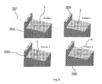
- a measuring stand 200 is schematically shown 4 times, with a vibrator 1 positioned thereon in 4 different measuring orientations, labelled 1,2,3,4 on top of the measuring stand 200.
- the size of the air gab may be measured with the vibrator oriented according to each of the positions during final assembly of the vibrator.
- Line 201 indicates the beam direction of a light beam, such as a laser beam, used to determine the size of the air gap.
- the beam will radiate into one of the 4 windows and a size measure of the air gap is registered, and this is repeated by sitting the vibrator in the 4 positions indicated and taking the measure in each position.
- the 4 obtained air gap measures are to fall within a predetermined interval in order for the vibrator to be declared usable.
- the 3 adjustment screws 111 (not seen in fig. 6 , where the device is placed head down) are possibly turned between measurements in order to obtain this.
Landscapes
- Health & Medical Sciences (AREA)
- General Health & Medical Sciences (AREA)
- Otolaryngology (AREA)
- Neurosurgery (AREA)
- Physics & Mathematics (AREA)
- Engineering & Computer Science (AREA)
- Acoustics & Sound (AREA)
- Signal Processing (AREA)
- Apparatuses For Generation Of Mechanical Vibrations (AREA)
- Reciprocating, Oscillating Or Vibrating Motors (AREA)
- Mobile Radio Communication Systems (AREA)
Abstract
A vibrator is provided with a spring having a first end and a second end and, a frame immovably attached to the second end where the frame is carrying a movable armature and at the second end of the spring a coupling with an armature plate is immovably attached. The armature plate and the movable armature are provided in close proximity with an air gap there between and a permanent magnet is associated with one or both of the armature plate and/or the movable armature and an electrical coil is associated with one or both of the armature plate and/or the movable armature. An adjustment screw is provided to displace the movable armature towards or away from the armature plate, wherein the screw is inserted in a bore. In an aspect of the invention, the bore has a length axis placed along a plane of intersection between the movable armature and the frame and one part of the bore is provided in the movable armature and an opposed part of the bore is provided in the frame, whereby one part of the bore is threaded and the opposed part is unthreaded.
Description
- In bone conduction vibrators a very small air gap is provided between a first and a second armature part, where these parts are attached to each their end of a spring. By energizing at least one of the armatures through an electromagnetic element, the two parts may be caused to vibrate towards and away from each other with maximum amplitude defined by the air gap. The size of the air gap is paramount to the energy efficiency of the vibrator and should be kept as small as possible, while at the same time, large amplitude is wished. For this reason a very precise adjustment of the air gap is very important.
- From
US patent 2143130 a bone conduction hearing aid device is known, wherein a set screw with a shoulder portion engaging the opposite surface of a core cross piece is provided, so that by turning the set screw a pole piece core is deformed and withdrawn from its contact with the armature and retained in a fixed position in which a small effective magnetic gap of a fraction of a thousandth of an inch is maintained between the pole faces of the pole pieces and the armature during operation of the receiver. - Constructions effecting similar adjustment of the air gap are found in prior art documents
GB444175 US 2, 127, 468 ;US 1,356,156 andUS 2, 680, 157 . - In a further prior art example, the air gap is adjusted through grinding of a distance element as is explained in the following.
- A vibrator is provided with a spring having a first end and a second end and, a frame immovably attached to the second end where the frame is carrying a movable armature and at the second end of the spring a coupling with an armature plate is immovably attached. The armature plate and the movable armature are provided in close proximity with an air gap there between and a permanent magnet is associated with one or both of the armature plate and/or the movable armature and an electrical coil is associated with one or both of the armature plate and/or the movable armature. An adjustment screw is provided to displace the movable armature towards or away from the armature plate, wherein the screw is inserted in a bore. In an aspect of the invention, the bore has a length axis placed along a plane of intersection between the movable armature and the frame and one part of the bore is provided in the movable armature and an opposed part of the bore is provided in the frame, whereby one part of the bore is threaded and the opposed part is unthreaded.
- With this vibrator, the air gap is adjustable by turning of the screw placed in the bore. By axially arresting the movement of the screw with respect to the one part and turning the screw, the interaction between the threads on the screw shaft and the thread in the other part, will move this other part up or down in correspondence with the direction of rotation of the screw. When the screw is rotated in this position, the surface part of the bore with no threads will function as a bearing wherein the threaded screw shaft rotates without axial movement of the screw with respect to this surface part.
- The threaded part of the bore may be provided in the movable armature and an arrest surface may be provided in the frame adjacent the bore and may be adapted to interact with a part of the screw and arresting motion of the screw in at least one axial direction. In this way the screw will be lifting the movable armature away from the armature plate when continued rotation of the screw is performed.
- The screw may at a first end thereof comprise a tool engaging portion for turning the screw. Such a tool engaging portion is well known in the art and may comprise internal or external hexagons or a simple slot. A well known standard tool can be made to interact with the screw when such a tool engaging part is provided.
- A radially extending flange may be provided at the tool engaging portion adapted to abut the arrest surface at the frame. In the event that the screw comprises a head portion, the underside of such a head portion may well work to abut the arrest surface and block further downbore motion of the screw, despite continued rotation thereof.
- A radially extending surface may be provided at a screw part disposed at the opposite end relative to the tool engaging portion and adapted to abut an arrest surface of the frame. Such a radially extending surface may simply be the end part of the screw shaft being ground more or less even. This end portion may thus abut an end portion of the bore part in the frame.
- Tree screws may be provided and spaced evenly around the circumference of the electrical coil. This allows the movable armature to be lifted without tilt with respect to the axis of the armature plate.
-
-
Fig. 1 shows an exploded view of a first embodiment of the invention, -
Figs 2 and2a shows a section in a 3D projection of the vibrator disclosed infig. 1 -
Fig. 3 is an exploded view of a further embodiment of the invention, and -
Figs. 4 and4a shows this embodiment in a sectional view in 3D projection, -
Figs. 5 and5a shows a section in a 3D projection of a further embodiment of the invention, -
Fig. 6 shows 4 representations of a measuring stand with a vibrator mounted thereon in different measuring orientations. - With reference to
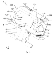
figs. 1 and2 the elements of the vibrator are described in detail. The central part of thevibrator 1 is thespring 2, which at afirst end 12 thereof is fastened to acoupling 3 and anarmature plate 4. Thecoupling 3 is shaped to couple immovable to a body, which is to receive vibrations. In the present case this body is the skull bone (not shown) of a hearing aid user, and the coupling will be fastened to a screw (not shown) which is implanted in the skull bone of the user. Alternatively the coupling is pressed towards a user's skin at the skull by use of a headband or similar device to provide a sufficient contact pressure in order to transfer vibrations through the skin and into the skull bone. At theopposed end 13 of thespring 2, aframe 100 is immovably fastened. Theframe 100 carries amagnetic armature armature plate 4. Themagnetic armature armature plate 4, and the magnetic force is balanced by thespring 2 to keep a distance between the two. In the embodiment shown thespring 2 is a flat, blade spring, wherein thefirst part 12 of the spring is the centre thereof and wherein thesecond part 13 is the outer peripheral edge thereof. - As seen in
fig. 1 and2 theframe 100 is connected to thespring 2 through adistance element 101. The spring is provided in a generally square shape with a screw opening 14 in each corner and through each opening 14 ascrew 15 passes and fastens into theframe 100 throughholes 102 in thedistance element 101. The four corners of thespring 2 are in this manner fastened immovably to theframe 100. Similarly the centre part of thespring 2 defined by theopening 12 is immovably fastened to thecoupling armature 4 by screwfastening thearmature plate 4 to thecoupling 3 from each their side of theopening 12. - In order for the proper functioning of the vibrator, the
armature plate 4 and themagnetic armature 110 are to be placed with a well defined distance between surfaces thereof, this distance being very small. This distance is termed "the air gap" throughout the application. - In a prior art method of adjusting the air gap, the thickness of the distance element is reduced in consecutive steps, until the right size of the air gap is reached. This process is slow and there is a risk that in the last step too much material is removed and the air gap becomes too small.
- According to the present invention the
magnetic armature 110 is suspended to be movable relative to theframe 100. The suspension comprisescrews 111 with threadedshafts 112 each placed in bores provided in the intersection between theframe 100 and themagnetic armature 110. For stability reasons threescrews 111 are provided evenly spaced around the periphery of themagnetic armature 110. The bores each comprise a threadedpart 115 thereof provided in themagnetic armature 110 and a not threadedpart 116 provided in theframe 100. The threadedshaft 112 will slide in the not threadedpart 116 in theframe 100 whereas the threads ofshaft 112 will fit the threads of the threadedpart 115 of the bore. Thescrews 111 also comprise heads, with a radially extendingflange 117 provided at an underside thereof. Thisflange 117 is provided to abut an arrest surface of theframe 100 such that thescrew shaft 112 is barred from further downward movement. When the screw is turned in abutment with theframe 100, it will carry and lift the magnetic armature when each screw is turned in the bore with the threads of thescrew shaft 112 in operative engagement with the threads of the threadedpart 115. Arecess 103 in themagnetic armature 110 is provided with a depth sufficient to not interfere with theflange 117 when thearmature 110 is lifted by the turning ofscrew 111 with abutment between theflange 117 and the arrest surface. If need be, a small pressure shall be supplied to the screw head, in order to assure abutment with the frame when the armature is lifted or lowered. - When the
screw 111 is turned beyond the abutment point between theflange 117 and the adjacent surface of theframe 100, thearmature 110 will be lifted away from thearmature plate 4 and theair gap 130 between these two parts will be increased. If thescrew 111 is turned in the opposite direction the air gap is decreased. In this way theair gap 130 may be easily adjusted by turning each of the threescrews 111 the same angle past the point of abutment as described above. Eachscrew 111 has aslot 118 in the head thereof to accomplish this turning. Once the right size of the air gap (indicated by arrow 130) is reached, the frame and armature may be permanently joined by any ordinary way, such as by use of glue or cement, soldering, welding as by laser, arresting screws or the like as well known in the art. - In a (not shown) embodiment the screw will abut at its lower end onto a flange part provided at the bottom of the half bore in the
frame 100. If this is provided, the screw can be made without aradially extending flange 117, as the lower end of the screw will abut a flange, when the desired depth is reached, and it is desired, that further turning of the screw is to lift or lower the magnetic armature. A slot must still be provided, such as hexagon or other slot at the top of the screw. - As seen in
fig. 1 and2 , theframe 100 is open at a top part thereof, allowing access to thearmature 110, and also allowing easy application of glue or the like when the right size of theair gap 130 is reached. - The
magnetic armature 110 comprises amagnetic ring 120 joined therewith, and centrally in the magnetic armature anelectric coil 140 is provided and by serving an electric audio signal at thecoil 140 the magnetic attraction between the magnetic armature and the armature plate may be biased, in correspondence to the audio signal, which in turn will cause theair gap 130 to change its width in correspondence with the audio signal, and balancing the masses attached to each its side of thespring 2, a vibrational signal with a frequency content corresponding to the audio signal may be served through thecoupling 3 and fed into a skull bone of a hearing impaired person wearing the device. - A
soft spring 8 is provided and attached at thecoupling 3, allowing a housing to be suspended from thevibrator 1. The housing may comprise a battery, and other electronic parts adapted for capturing sound and processing the resulting electric signal in order to provide an electric signal to be served at thecoil 140. - In
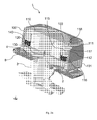
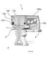
Figs. 3 ,4 and4a a further embodiment of the invention is presented. Here theframe 100 comprises a domed structure, withholes 122 provided therein for insertion of thescrews 111. The domed structure lends more mass to the frame. This is important as the frame also provides a counter weight property to the vibrator, which serves to maximise the force amplitude of the vibrations served at thecoupling 3. - In both embodiments it is intended to cement the
frame 100 and themagnetic armature 103 to each other after adjustment of theair gap 130, but when using thedomed frame 100 shown infigs. 3 ,4 and4a it is not easy to apply the cement, and to solve this problem, a number of cementingholes 123 are provided in thedomed frame 100. Also to improve the distribution of the glue or cement adistribution channel 124 is provided inside the dome. This channel runs all the way round the inside surface of the dome, and will ensure a secure and even distribution of glue, when applied through theholes 123. Infigs. 3 ,4 and4a , the coil is not disclosed, and infig. 4 and4a thereference number 140 refers to the space inside the armature where the coil is to be inserted. - In
fig. 5 and5a a further embodiment of the invention is shown, wherein theframe 100 anddistance element 101 are made to constitute asingle frame piece 100a. This makes the vibrator a little simpler to produce, however pairs ofwindows 150 must be provided in theframepiece 100a in order that an optical instrument may be used in measuring the size of the air gap during adjustment of the size thereof as disclosed above. Thewindows 150 are provided in opposite positions on all 4 sides of the framepiece 100a. - In
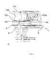
fig. 6 a measuringstand 200 is schematically shown 4 times, with avibrator 1 positioned thereon in 4 different measuring orientations, labelled 1,2,3,4 on top of the measuringstand 200. The size of the air gab may be measured with the vibrator oriented according to each of the positions during final assembly of the vibrator.Line 201 indicates the beam direction of a light beam, such as a laser beam, used to determine the size of the air gap. The beam will radiate into one of the 4 windows and a size measure of the air gap is registered, and this is repeated by sitting the vibrator in the 4 positions indicated and taking the measure in each position. The 4 obtained air gap measures are to fall within a predetermined interval in order for the vibrator to be declared usable. The 3 adjustment screws 111 (not seen infig. 6 , where the device is placed head down) are possibly turned between measurements in order to obtain this. - In the
Figs. 3 ,4 ,4a ,5 and5a all parts corresponding to similar or identical parts inFigs. 1 ,2 and2a are labelled with the same reference numbers.
Claims (8)
- Vibrator (1) with a spring (2) having a first end (12) and a second end (13), a frame (100) immovably attached to the second end (13), the frame (100) carrying a movable armature (110) and at the second end (13) of the spring (2) a coupling (3) with an armature plate (4) is immovably attached, whereby the armature plate (4) and the movable armature (110) are provided in close proximity with an air gap (130) there between, a permanent magnet (120) associated with one or both of the armature plate (4) and/or the movable armature (110), an electrical coil (140) associated with one or both of the armature plate (4) and/or the movable armature (110), an adjustment screw (111) provided to displace the movable armature (110) towards or away from the armature plate (4), wherein the screw (111) is inserted in a bore (115; 112), wherein the bore has a length axis placed along a plane of intersection between the movable armature (110) and the frame (100) wherein one part of the bore is provided in the movable armature (110) and an opposed part of the bore is provided in the frame, and one part of the bore is threaded and the opposed part is unthreaded.
- Vibrator 1 as claimed in claim 1, wherein the threaded part of the bore is provided in the movable armature (110), and an arrest surface is provided in the frame (100) adjacent the bore and adapted to interact with a part of the screw and arresting motion of the screw in at least one axial direction.
- Vibrator as claimed in claim 1, wherein the screw at a first end thereof comprises a tool engaging portion for turning the screw.
- Vibrator as claimed in claim 3, wherein a radially extending flange is provided at the tool engaging portion adapted to abut the arrest surface at the frame.
- Vibrator as claimed in claim 3, wherein a radially extending surface is provided at a screw part disposed at the opposite end relative to the tool engaging portion and adapted to abut an arrest surface of the frame.
- Vibrator as claimed in any of the above claims, wherein three or more screws are provided and spaced evenly around the circumference of the electrical coil.
- Method for adjusting the air gap of a vibrator as claimed in claim 1,
wherein the size of the air gap (130) is measured with an optical instrument, and the adjustment screws (111) are turned to obtain a pre-determined air gap size. - Method as claimed in claim 7, wherein the frame (100) and movable armature (110) are fastened to one another when the air gap size is adjusted to a predetermined measure.
Priority Applications (6)
| Application Number | Priority Date | Filing Date | Title |
|---|---|---|---|
| EP10167651A EP2403271A1 (en) | 2010-06-29 | 2010-06-29 | Vibrator with adjustment system |
| EP11170097.7A EP2403272B1 (en) | 2010-06-29 | 2011-06-16 | Vibrator with adjustment system |
| DK11170097.7T DK2403272T3 (en) | 2010-06-29 | 2011-06-16 | Vibrating with adjustment system |
| CN201110176419.9A CN102386743B (en) | 2010-06-29 | 2011-06-23 | With the vibrator of regulating system |
| US13/171,197 US8837761B2 (en) | 2010-06-29 | 2011-06-28 | Vibrator with adjustment system |
| AU2011203159A AU2011203159B2 (en) | 2010-06-29 | 2011-06-29 | Vibrator With Adjustment System |
Applications Claiming Priority (1)
| Application Number | Priority Date | Filing Date | Title |
|---|---|---|---|
| EP10167651A EP2403271A1 (en) | 2010-06-29 | 2010-06-29 | Vibrator with adjustment system |
Publications (1)
| Publication Number | Publication Date |
|---|---|
| EP2403271A1 true EP2403271A1 (en) | 2012-01-04 |
Family
ID=43086334
Family Applications (2)
| Application Number | Title | Priority Date | Filing Date |
|---|---|---|---|
| EP10167651A Withdrawn EP2403271A1 (en) | 2010-06-29 | 2010-06-29 | Vibrator with adjustment system |
| EP11170097.7A Active EP2403272B1 (en) | 2010-06-29 | 2011-06-16 | Vibrator with adjustment system |
Family Applications After (1)
| Application Number | Title | Priority Date | Filing Date |
|---|---|---|---|
| EP11170097.7A Active EP2403272B1 (en) | 2010-06-29 | 2011-06-16 | Vibrator with adjustment system |
Country Status (5)
| Country | Link |
|---|---|
| US (1) | US8837761B2 (en) |
| EP (2) | EP2403271A1 (en) |
| CN (1) | CN102386743B (en) |
| AU (1) | AU2011203159B2 (en) |
| DK (1) | DK2403272T3 (en) |
Cited By (1)
| Publication number | Priority date | Publication date | Assignee | Title |
|---|---|---|---|---|
| EP2838277A1 (en) * | 2013-08-14 | 2015-02-18 | Oticon Medical A/S | Holding unit for a vibration transmitter and a vibration transmission system using it |
Families Citing this family (3)
| Publication number | Priority date | Publication date | Assignee | Title |
|---|---|---|---|---|
| GB2532436B (en) * | 2014-11-18 | 2017-01-11 | Ps Audio Design Oy | Loudspeaker apparatus |
| US11234080B2 (en) | 2014-11-18 | 2022-01-25 | Ps Audio Design Oy | Apparatus with surface to be displaced |
| EP3873111A1 (en) * | 2017-11-14 | 2021-09-01 | Oticon Medical A/S | Bone conduction hearing aid with an air gap adjustment mechanism |
Citations (6)
| Publication number | Priority date | Publication date | Assignee | Title |
|---|---|---|---|---|
| US1356156A (en) | 1917-10-10 | 1920-10-19 | Internat Callophone Corp | Telephonic receiver |
| GB444175A (en) | 1933-08-11 | 1936-03-13 | Sonotone Corp | Improvements in bone-conduction hearing-aids |
| US2127468A (en) | 1933-11-11 | 1938-08-16 | Emil Henry Greibach | Bone conduction hearing device |
| US2143130A (en) | 1936-07-01 | 1939-01-10 | Sonotone Corp | Bone conduction hearing-aid device |
| US2500541A (en) * | 1945-07-18 | 1950-03-14 | Emil H Greibach | Inertia-type electromechanical sound transducing device |
| US2680157A (en) | 1949-07-25 | 1954-06-01 | Fortiphone Ltd | Bone conduction telephone receiver |
Family Cites Families (11)
| Publication number | Priority date | Publication date | Assignee | Title |
|---|---|---|---|---|
| US5460593A (en) * | 1993-08-25 | 1995-10-24 | Audiodontics, Inc. | Method and apparatus for imparting low amplitude vibrations to bone and similar hard tissue |
| US5410781A (en) * | 1993-12-13 | 1995-05-02 | Tridon Limited | Constant tension clamp |
| KR100344091B1 (en) * | 2000-04-18 | 2002-07-24 | 주식회사 도우미텍 | Arousing bone vibrator and speaker headset for arousing bone using the same |
| JP3556168B2 (en) * | 2000-12-27 | 2004-08-18 | 株式会社テムコジャパン | Bone conduction speaker |
| US6688802B2 (en) * | 2001-09-10 | 2004-02-10 | Siemens Westinghouse Power Corporation | Shrunk on industrial coupling without keys for industrial system and associated methods |
| KR100593917B1 (en) * | 2004-06-23 | 2006-06-30 | 삼성전기주식회사 | A vertical vibrator |
| SE528279C2 (en) * | 2005-02-21 | 2006-10-10 | Entific Medical Systems Ab | Vibrator for bone conductive hearing aid |
| ITRM20050211A1 (en) * | 2005-05-04 | 2006-11-05 | Coselgi Spa | BONE TRANSDUCER TRANSFER. |
| US7801319B2 (en) * | 2006-05-30 | 2010-09-21 | Sonitus Medical, Inc. | Methods and apparatus for processing audio signals |
| KR100992096B1 (en) * | 2007-11-20 | 2010-11-04 | 주식회사 알에프컴 | Bone conduction speaker |
| GB2457489B (en) * | 2008-02-15 | 2012-10-31 | Itw Ltd | Adjustable needle seal |
-
2010
- 2010-06-29 EP EP10167651A patent/EP2403271A1/en not_active Withdrawn
-
2011
- 2011-06-16 EP EP11170097.7A patent/EP2403272B1/en active Active
- 2011-06-16 DK DK11170097.7T patent/DK2403272T3/en active
- 2011-06-23 CN CN201110176419.9A patent/CN102386743B/en active Active
- 2011-06-28 US US13/171,197 patent/US8837761B2/en active Active
- 2011-06-29 AU AU2011203159A patent/AU2011203159B2/en active Active
Patent Citations (6)
| Publication number | Priority date | Publication date | Assignee | Title |
|---|---|---|---|---|
| US1356156A (en) | 1917-10-10 | 1920-10-19 | Internat Callophone Corp | Telephonic receiver |
| GB444175A (en) | 1933-08-11 | 1936-03-13 | Sonotone Corp | Improvements in bone-conduction hearing-aids |
| US2127468A (en) | 1933-11-11 | 1938-08-16 | Emil Henry Greibach | Bone conduction hearing device |
| US2143130A (en) | 1936-07-01 | 1939-01-10 | Sonotone Corp | Bone conduction hearing-aid device |
| US2500541A (en) * | 1945-07-18 | 1950-03-14 | Emil H Greibach | Inertia-type electromechanical sound transducing device |
| US2680157A (en) | 1949-07-25 | 1954-06-01 | Fortiphone Ltd | Bone conduction telephone receiver |
Cited By (3)
| Publication number | Priority date | Publication date | Assignee | Title |
|---|---|---|---|---|
| EP2838277A1 (en) * | 2013-08-14 | 2015-02-18 | Oticon Medical A/S | Holding unit for a vibration transmitter and a vibration transmission system using it |
| US9271094B2 (en) | 2013-08-14 | 2016-02-23 | Oticon Medical A/S | Holding unit for a vibration transmitter and a vibration transmission system using it |
| US9554224B2 (en) | 2013-08-14 | 2017-01-24 | Oticon Medical A/S | Holding unit for a vibration transmitter and a vibration transmission system using it |
Also Published As
| Publication number | Publication date |
|---|---|
| US20110317859A1 (en) | 2011-12-29 |
| CN102386743A (en) | 2012-03-21 |
| DK2403272T3 (en) | 2016-11-21 |
| EP2403272A1 (en) | 2012-01-04 |
| EP2403272B1 (en) | 2016-08-17 |
| US8837761B2 (en) | 2014-09-16 |
| CN102386743B (en) | 2015-08-19 |
| AU2011203159B2 (en) | 2015-12-24 |
| AU2011203159A1 (en) | 2012-01-19 |
Similar Documents
| Publication | Publication Date | Title |
|---|---|---|
| EP2403272B1 (en) | Vibrator with adjustment system | |
| EP2608574B1 (en) | Adjustable spring assembly for a vibrator of a bone anchored hearing aid | |
| US10757516B2 (en) | Electromagnetic transducer with specific interface geometries | |
| US9716953B2 (en) | Electromagnetic transducer with specific internal geometry | |
| EP1425939B1 (en) | A coupling device for a two-part bone-anchored hearing aid apparatus | |
| US6670877B2 (en) | Field adjusting mechanisms and methods for permanent magnet arrangement with backplate | |
| US9066188B2 (en) | Acoustic transmission method and listening device | |
| AU2006302791A1 (en) | Inertial voice type coil actuator systems | |
| WO2006096734B1 (en) | System and method for a low profile vibrating plate | |
| US11778385B2 (en) | Electromagnetic transducer with non-axial air gap | |
| CN104729405B (en) | Support device for sample work piece | |
| CN109996153B (en) | Bone conduction hearing aid with air gap adjusting mechanism | |
| KR20110004713A (en) | Bone conductive speaker | |
| AU2016323458B2 (en) | Bone conduction transducer system with adjustable retention force | |
| RU194800U1 (en) | ACOUSTIC UNIT | |
| CN116830602A (en) | Transducer with new spring attachment | |
| CN221688836U (en) | Miniature columnar low-frequency vibrator | |
| CN216759078U (en) | Disc-shaped workpiece surface machining fixing device and surface machining equipment | |
| US10454304B2 (en) | Inductive power transfer coil assembly and system | |
| CN207541374U (en) | A kind of magnetic-type filter support | |
| WO2021012433A1 (en) | Multi-degree-of-freedom piezoelectric actuator with spherical rotor | |
| EP2437382A1 (en) | Electromagnetic motor | |
| 濱西伸治 | Development of a new electromagnetic hearing aid with coils to vibrate the ossicles | |
| JPS61110021A (en) | Torque detector | |
| LV13975A (en) | Therapeutic device enabling oscillations of magnetic field |
Legal Events
| Date | Code | Title | Description |
|---|---|---|---|
| AK | Designated contracting states |
Kind code of ref document: A1 Designated state(s): AL AT BE BG CH CY CZ DE DK EE ES FI FR GB GR HR HU IE IS IT LI LT LU LV MC MK MT NL NO PL PT RO SE SI SK SM TR |
|
| AX | Request for extension of the european patent |
Extension state: BA ME RS |
|
| PUAI | Public reference made under article 153(3) epc to a published international application that has entered the european phase |
Free format text: ORIGINAL CODE: 0009012 |
|
| 17P | Request for examination filed |
Effective date: 20120704 |
|
| STAA | Information on the status of an ep patent application or granted ep patent |
Free format text: STATUS: THE APPLICATION IS DEEMED TO BE WITHDRAWN |
|
| 18D | Application deemed to be withdrawn |
Effective date: 20120705 |