EP2403124A2 - Time delay contactor for aircraft APU starter - Google Patents
Time delay contactor for aircraft APU starter Download PDFInfo
- Publication number
- EP2403124A2 EP2403124A2 EP11169864A EP11169864A EP2403124A2 EP 2403124 A2 EP2403124 A2 EP 2403124A2 EP 11169864 A EP11169864 A EP 11169864A EP 11169864 A EP11169864 A EP 11169864A EP 2403124 A2 EP2403124 A2 EP 2403124A2
- Authority
- EP
- European Patent Office
- Prior art keywords
- direct current
- current motor
- starter
- relay
- time
- Prior art date
- Legal status (The legal status is an assumption and is not a legal conclusion. Google has not performed a legal analysis and makes no representation as to the accuracy of the status listed.)
- Withdrawn
Links
- 239000007858 starting material Substances 0.000 title claims abstract description 35
- 230000000977 initiatory effect Effects 0.000 claims abstract description 7
- XUIMIQQOPSSXEZ-UHFFFAOYSA-N Silicon Chemical compound [Si] XUIMIQQOPSSXEZ-UHFFFAOYSA-N 0.000 claims description 11
- 229910052710 silicon Inorganic materials 0.000 claims description 11
- 239000010703 silicon Substances 0.000 claims description 11
- 238000000034 method Methods 0.000 claims description 8
- 230000005669 field effect Effects 0.000 claims description 3
- 239000004065 semiconductor Substances 0.000 claims description 3
- 230000003111 delayed effect Effects 0.000 claims 2
- 230000035939 shock Effects 0.000 description 4
- 230000001133 acceleration Effects 0.000 description 2
- 230000000694 effects Effects 0.000 description 2
- 230000001960 triggered effect Effects 0.000 description 2
- 230000004075 alteration Effects 0.000 description 1
- 239000003990 capacitor Substances 0.000 description 1
- 230000006835 compression Effects 0.000 description 1
- 238000007906 compression Methods 0.000 description 1
- 238000006467 substitution reaction Methods 0.000 description 1
Images
Classifications
-
- F—MECHANICAL ENGINEERING; LIGHTING; HEATING; WEAPONS; BLASTING
- F02—COMBUSTION ENGINES; HOT-GAS OR COMBUSTION-PRODUCT ENGINE PLANTS
- F02N—STARTING OF COMBUSTION ENGINES; STARTING AIDS FOR SUCH ENGINES, NOT OTHERWISE PROVIDED FOR
- F02N15/00—Other power-operated starting apparatus; Component parts, details, or accessories, not provided for in, or of interest apart from groups F02N5/00 - F02N13/00
- F02N15/02—Gearing between starting-engines and started engines; Engagement or disengagement thereof
- F02N15/022—Gearing between starting-engines and started engines; Engagement or disengagement thereof the starter comprising an intermediate clutch
-
- F—MECHANICAL ENGINEERING; LIGHTING; HEATING; WEAPONS; BLASTING
- F02—COMBUSTION ENGINES; HOT-GAS OR COMBUSTION-PRODUCT ENGINE PLANTS
- F02C—GAS-TURBINE PLANTS; AIR INTAKES FOR JET-PROPULSION PLANTS; CONTROLLING FUEL SUPPLY IN AIR-BREATHING JET-PROPULSION PLANTS
- F02C7/00—Features, components parts, details or accessories, not provided for in, or of interest apart form groups F02C1/00 - F02C6/00; Air intakes for jet-propulsion plants
- F02C7/26—Starting; Ignition
- F02C7/268—Starting drives for the rotor, acting directly on the rotor of the gas turbine to be started
- F02C7/275—Mechanical drives
-
- F—MECHANICAL ENGINEERING; LIGHTING; HEATING; WEAPONS; BLASTING
- F02—COMBUSTION ENGINES; HOT-GAS OR COMBUSTION-PRODUCT ENGINE PLANTS
- F02N—STARTING OF COMBUSTION ENGINES; STARTING AIDS FOR SUCH ENGINES, NOT OTHERWISE PROVIDED FOR
- F02N11/00—Starting of engines by means of electric motors
- F02N11/08—Circuits specially adapted for starting of engines
- F02N11/0851—Circuits specially adapted for starting of engines characterised by means for controlling the engagement or disengagement between engine and starter, e.g. meshing of pinion and engine gear
-
- F—MECHANICAL ENGINEERING; LIGHTING; HEATING; WEAPONS; BLASTING
- F02—COMBUSTION ENGINES; HOT-GAS OR COMBUSTION-PRODUCT ENGINE PLANTS
- F02N—STARTING OF COMBUSTION ENGINES; STARTING AIDS FOR SUCH ENGINES, NOT OTHERWISE PROVIDED FOR
- F02N2300/00—Control related aspects of engine starting
- F02N2300/20—Control related aspects of engine starting characterised by the control method
- F02N2300/2011—Control involving a delay; Control involving a waiting period before engine stop or engine start
-
- F—MECHANICAL ENGINEERING; LIGHTING; HEATING; WEAPONS; BLASTING
- F05—INDEXING SCHEMES RELATING TO ENGINES OR PUMPS IN VARIOUS SUBCLASSES OF CLASSES F01-F04
- F05D—INDEXING SCHEME FOR ASPECTS RELATING TO NON-POSITIVE-DISPLACEMENT MACHINES OR ENGINES, GAS-TURBINES OR JET-PROPULSION PLANTS
- F05D2220/00—Application
- F05D2220/50—Application for auxiliary power units (APU's)
Definitions
- the subject matter disclosed herein relates to an auxiliary power unit (APU) for aircraft. More specifically, the subject disclosure relates to a starter motor for an APU.
- APU auxiliary power unit
- An APU is utilized in an aircraft primarily to provide power to start the engines. Aircraft engines have large heavy rotors that must be accelerated to a high rotational speed in order to provide sufficient air compression for self-sustaining operation.
- An APU solves this problem by powering up the aircraft in two stages.
- the APU is started by an APU starter, which is a DC electric motor with power supplied by a battery, accumulator, or external power source such as a ground power unit. Once the APU accelerates to full speed, it can provide enough power to start the aircraft's main engines, either by turning an electrical generator or a hydraulic pump, or by providing compressed air to the air turbine of the starter motor.
- a starter for an auxiliary power unit includes a direct current motor operably connectable to an auxiliary power unit.
- a clutch is arranged in an electrically parallel relationship and configured to operably connect the motor to the auxiliary power unit when engaged, the motor and the clutch being powered by a common input line.
- a time delay switching element is located and configured to delay electrical current delivery to the motor thus providing for full engagement of the clutch prior to initiation of rotation of the motor.
- a method of starting an auxiliary power unit includes providing a flow of electrical current to a clutch of a starter.
- the clutch is fully engaged via the flow of current, thus operably connecting the direct current motor to the auxiliary power unit.
- a time-delayed flow of electrical current is provided to a direct current motor of the starter located such that it shares a common input line with the clutch.
- the direct current motor is accelerated via the time-delayed flow of current, and rotational energy is transferred from the direct current motor to the auxiliary power unit.
- FIG. 1 is a schematic view of an embodiment of a starter for a auxiliary power unit
- FIG. 2 is an electrical schematic view of an embodiment of a starter for an auxiliary power unit
- FIG. 3 is an electrical schematic view of another embodiment of a starter for an auxiliary power unit
- FIG. 4 is an electrical schematic view of yet another embodiment of a starter for an auxiliary power unit.
- FIG. 5 is an electrical schematic of still another embodiment of a starter for an auxiliary power unit.
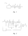
- FIG. 1 Shown in FIG. 1 is a schematic of a starter 10 for an auxiliary power unit (APU) 12.
- the starter 10 includes an electric motor, for example, a direct current (DC) motor 14 and a motor shaft 18 extending therefrom.
- a starter shaft 20 extends from the APU 12 and is connectable to the motor shaft 18 via a clutch 22. When the clutch 22 is engaged, rotational energy is transferred from the DC motor 14, through the motor shaft 18 and starter shaft 20, and to the APU 12.
- DC direct current
- the DC motor 14 and the clutch 22 are arranged in an electrically parallel relationship and are powered by a common input line 24 from a power supply 26.
- An APU controller 28 controls a flow of current through the input line 24 via signals to one or more contactors 30.
- the DC motor 14 accelerates up to a desired rotational speed.
- the clutch 22 operably connects a starter shaft 20 to the motor shaft 18 thus enabling the transfer of rotational energy from the DC motor 14 to the APU 12.
- a time delay switching element for example, a relay 32.
- time delay control electronics that drive the relay 32 are activated, thus initiating a time delay, before the current flows to the DC motor 14.
- the time delay effect of the relay 32 allows the clutch 22 to fully engage prior to initiation of acceleration of the DC motor 14 thus reducing torque shock when the clutch 22 is engaged.
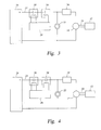
- MOSFET 34 metal-oxide-semiconductor field-effect transistor 34 which acts as the time delay switching element.
- the MOSFET 34 is arranged in a serial relationship with the DC motor 14. When current passes through the input line 24 to the MOSFET 34, time delay control electronics that drive the MOSFET 34 are activated, thus initiating a time delay, before the current proceeds to the DC motor 14. The time delay effect of the MOSFET 34 allows the clutch 22 to fully engage prior to initiation of acceleration of the DC motor 14.
- starter 10 include a switching element which is a thyristor 36.
- a switching element which is a thyristor 36.
- the relay 32 and the MOSFET 34 when current is delivered to the thyristor 36 via the input line 24, a time delay is initiated via the time delay control electronics that drive the thyristor 36.
- the thyristor 36 Once the thyristor 36 is triggered, it will continue to conduct, or provide current to the DC motor 14 until the voltage across the thyristor 36 is reversed. In other words, the thyristor 36 is latched in a closed position. Further, the thyristor 36 is operable at a wide range of temperatures, and those as low as -50 degrees Celsius or lower.
- the desired range of time delay is in a range of about 0.250 seconds to 2.0 seconds, with a target delay of about 0.500 seconds to allow the clutch 22 to fully engage prior to supplying current to the DC motor 14 to prevent damage to the starter shaft 20 and/or other elements of the starter 10 or APU 12.
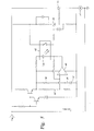
- FIG. 5 illustrates another embodiment.
- Voltage V in is turned on via the contactors 30 (shown in FIG. 4 ).
- the time delay is established via a comparator 40 which trips a relay 42 to provide power to a silicon-controlled rectifier (SCR) 44.
- the relay may be optically driven relay with an internal light emitting diode 54 configured to change a switch state of the relay 42.
- the comparator 40 compares a comparator reference voltage 46 to a time-delayed voltage 48.
- the time-delay is created by a resistor 50 and capacitor 52. When the time-delayed voltage exceeds the reference voltage, the comparator 40 trips the relay 42 which, in turn energizes the SCR 44.
- the SCR 44 can energize a second SCR 56 in response to the SCR 44 being energized by the relay 42 to provide current to the DC motor 14. Because of the time delay provided by the comparator 40, the current is provided to the DC motor 14 after current is provided to the clutch 22 (shown in FIG. 4 ) and the clutch 22 is fully engaged.
Landscapes
- Engineering & Computer Science (AREA)
- Chemical & Material Sciences (AREA)
- Combustion & Propulsion (AREA)
- Mechanical Engineering (AREA)
- General Engineering & Computer Science (AREA)
- Control Of Direct Current Motors (AREA)
- Motor And Converter Starters (AREA)
- Connection Of Motors, Electrical Generators, Mechanical Devices, And The Like (AREA)
Abstract
A starter for an auxiliary power unit (12) includes a direct current motor (14) operably connectable to an auxiliary power unit. A clutch (22)is arranged in an electrically parallel relationship and configured to operably connect the motor to the auxiliary power unit when engaged, the motor and the clutch powered by a common input line (24). A time delay switching element (32;34;36) is located and configured to delay power delivery to the direct current motor thus providing for full engagement of the clutch prior to initiation of rotation of the motor.
Description
- The subject matter disclosed herein relates to an auxiliary power unit (APU) for aircraft. More specifically, the subject disclosure relates to a starter motor for an APU.
- An APU is utilized in an aircraft primarily to provide power to start the engines. Aircraft engines have large heavy rotors that must be accelerated to a high rotational speed in order to provide sufficient air compression for self-sustaining operation. An APU solves this problem by powering up the aircraft in two stages. The APU is started by an APU starter, which is a DC electric motor with power supplied by a battery, accumulator, or external power source such as a ground power unit. Once the APU accelerates to full speed, it can provide enough power to start the aircraft's main engines, either by turning an electrical generator or a hydraulic pump, or by providing compressed air to the air turbine of the starter motor.
- When starting the APU, power is supplied to the DC motor and a clutch which engages the APU to begin its operation. Typically, power is supplied to the DC motor and the clutch from the same electrical line, so that when the DC motor is activated, the clutch is simultaneously activated. The result is that the DC motor accelerates to speed before the clutch is completely engaged, and causes a high torque shock on a starter shaft when the clutch engages the shaft. The torque shock can cause damage and/or breakage of the shaft. The art would well receive an APU starter configuration which alleviates the torque shock and reduces damage and/or breakage of the starter shaft when the clutch is engaged.
- According to one aspect of the invention, a starter for an auxiliary power unit includes a direct current motor operably connectable to an auxiliary power unit. A clutch is arranged in an electrically parallel relationship and configured to operably connect the motor to the auxiliary power unit when engaged, the motor and the clutch being powered by a common input line. A time delay switching element is located and configured to delay electrical current delivery to the motor thus providing for full engagement of the clutch prior to initiation of rotation of the motor.
- According to another aspect of the invention, a method of starting an auxiliary power unit includes providing a flow of electrical current to a clutch of a starter. The clutch is fully engaged via the flow of current, thus operably connecting the direct current motor to the auxiliary power unit. A time-delayed flow of electrical current is provided to a direct current motor of the starter located such that it shares a common input line with the clutch. The direct current motor is accelerated via the time-delayed flow of current, and rotational energy is transferred from the direct current motor to the auxiliary power unit.
- These and other advantages and features will become more apparent from the following description taken in conjunction with the drawings.
- The subject matter, which is regarded as the invention, is particularly pointed out and distinctly claimed in the claims at the conclusion of the specification. The foregoing and other features, and advantages of the invention are apparent from the following detailed description taken in conjunction with the accompanying drawings in which:
-
FIG. 1 is a schematic view of an embodiment of a starter for a auxiliary power unit; -
FIG. 2 is an electrical schematic view of an embodiment of a starter for an auxiliary power unit; -
FIG. 3 is an electrical schematic view of another embodiment of a starter for an auxiliary power unit, -
FIG. 4 is an electrical schematic view of yet another embodiment of a starter for an auxiliary power unit; and -
FIG. 5 is an electrical schematic of still another embodiment of a starter for an auxiliary power unit. - The detailed description explains embodiments of the invention, together with advantages and features, by way of example with reference to the drawings.
- Shown in
FIG. 1 is a schematic of astarter 10 for an auxiliary power unit (APU) 12. Thestarter 10 includes an electric motor, for example, a direct current (DC)motor 14 and amotor shaft 18 extending therefrom. Astarter shaft 20 extends from the APU 12 and is connectable to themotor shaft 18 via aclutch 22. When theclutch 22 is engaged, rotational energy is transferred from theDC motor 14, through themotor shaft 18 andstarter shaft 20, and to theAPU 12. - Referring now to
FIG. 2 , theDC motor 14 and theclutch 22 are arranged in an electrically parallel relationship and are powered by acommon input line 24 from apower supply 26. AnAPU controller 28 controls a flow of current through theinput line 24 via signals to one ormore contactors 30. When theDC motor 14 is powered by theinput line 24, theDC motor 14 accelerates up to a desired rotational speed. Similarly, when theclutch 22 is powered by theinput line 24, theclutch 22 operably connects astarter shaft 20 to themotor shaft 18 thus enabling the transfer of rotational energy from theDC motor 14 to theAPU 12. - Located between the
DC motor 14 and theclutch 22, in a series relationship with theDC motor 14 is a time delay switching element, for example, arelay 32. When current passes through theinput line 24 to therelay 32, time delay control electronics that drive therelay 32 are activated, thus initiating a time delay, before the current flows to theDC motor 14. The time delay effect of therelay 32 allows theclutch 22 to fully engage prior to initiation of acceleration of theDC motor 14 thus reducing torque shock when theclutch 22 is engaged. - Referring now to
FIG. 3 , other embodiments include a metal-oxide-semiconductor field-effect transistor (MOSFET) 34 which acts as the time delay switching element. TheMOSFET 34 is arranged in a serial relationship with theDC motor 14. When current passes through theinput line 24 to theMOSFET 34, time delay control electronics that drive theMOSFET 34 are activated, thus initiating a time delay, before the current proceeds to theDC motor 14. The time delay effect of theMOSFET 34 allows theclutch 22 to fully engage prior to initiation of acceleration of theDC motor 14. - Referring now to
FIG. 4 , some embodiments ofstarter 10 include a switching element which is athyristor 36. As above regarding therelay 32 and theMOSFET 34, when current is delivered to thethyristor 36 via theinput line 24, a time delay is initiated via the time delay control electronics that drive thethyristor 36. Once thethyristor 36 is triggered, it will continue to conduct, or provide current to theDC motor 14 until the voltage across thethyristor 36 is reversed. In other words, thethyristor 36 is latched in a closed position. Further, thethyristor 36 is operable at a wide range of temperatures, and those as low as -50 degrees Celsius or lower. Regardless of the time delay element utilized, the desired range of time delay is in a range of about 0.250 seconds to 2.0 seconds, with a target delay of about 0.500 seconds to allow theclutch 22 to fully engage prior to supplying current to theDC motor 14 to prevent damage to thestarter shaft 20 and/or other elements of thestarter 10 orAPU 12. -
FIG. 5 illustrates another embodiment. Voltage Vin is turned on via the contactors 30 (shown inFIG. 4 ). In this embodiment, the time delay is established via acomparator 40 which trips arelay 42 to provide power to a silicon-controlled rectifier (SCR) 44. As can be seen inFig. 5 , the relay may be optically driven relay with an internallight emitting diode 54 configured to change a switch state of therelay 42. Thecomparator 40 compares acomparator reference voltage 46 to a time-delayed voltage 48. The time-delay is created by aresistor 50 andcapacitor 52. When the time-delayed voltage exceeds the reference voltage, thecomparator 40 trips therelay 42 which, in turn energizes theSCR 44. Once the SCR 44 is triggered, current may be provided to theDC motor 14. As can be seen inFig. 5 , theSCR 44 can energize asecond SCR 56 in response to the SCR 44 being energized by therelay 42 to provide current to theDC motor 14. Because of the time delay provided by thecomparator 40, the current is provided to theDC motor 14 after current is provided to the clutch 22 (shown inFIG. 4 ) and theclutch 22 is fully engaged. - While the invention has been described in detail in connection with only a limited number of embodiments, it should be readily understood that the invention is not limited to such disclosed embodiments. Rather, the invention can be modified to incorporate any number of variations, alterations, substitutions or equivalent arrangements not heretofore described, but which are commensurate with the scope of the invention as defined by the attached claims. Additionally, while various embodiments of the invention have been described, it is to be understood that aspects of the invention may include only some of the described embodiments. Accordingly, the invention is not to be seen as limited by the foregoing description, but is only limited by the scope of the appended claims.
Claims (15)
- A starter (10) for an auxiliary power unit (12) comprising:a direct current motor (14) operably connectable to an auxiliary power unit;a clutch (22) arranged in an electrically parallel relationship with the direct current motor and configured to operably connect the direct current motor to the auxiliary power unit when engaged, the direct current motor and the clutch being powered by a common input line (24); anda time delay switching element (32;34;36) disposed and configured to delay current delivery to the direct current motor thus providing for full engagement of the clutch prior to initiation of rotation of the direct current motor.
- The starter of Claim 1, wherein the time delay switching element is configured to provide a time delay of about 0.25 seconds to 2.0 seconds, and wherein the time delay is preferably about 0.5 seconds.
- The starter of Claim 1 or 2, wherein the clutch (22) operably engages the direct current motor (14) with a shaft of the auxiliary power unit.
- The starter of Claim 1, 2 or 3, wherein the time delay switching element is latchable in a closed position.
- The starter of any preceding Claim, wherein the time delay switching element comprises one of: a relay (32), a metal-oxide-semiconductor field-effect transistor (34), and a thyristor (36).
- The starter of claim 1, 2 or 3, wherein the time delay switching element includes:a comparator (40) configured to compare a reference voltage (46) to a time-delayed voltage (48); anda relay (42) electrically connected to the comparator (40) andconfigured to trip based on the result of the comparison to cause current to be supplied to the direct current motor (14), and preferably comprising a resistive element (50) and capacitive element (52) connected in series to provide a time-delayed voltage.
- The starter of claim 6 comprising a first silicon-controlled rectifier (44) electrically connect to the relay (42) and to the direct current motor (14) to provide electrical current to the direct current motor (14) in response to the relay (14), and preferably comprising a second silicon-controlled rectifier (56) electrically connected to the first silicon-controlled rectifier (44) to provide the electrical current to the direct current motor (14) in response to the first silicon-controlled rectifier (44) being energized by the relay.
- The starter of claim 6 or 7, wherein the relay comprises an internal light emitting diode (54) configured to change a switch state of the relay (42).
- A method of starting an auxiliary power unit (12) comprising:providing a flow of electrical current to a clutch (22) of a starter;fully engaging the clutch via the flow of electrical current, thus operably connecting a direct current motor (14) to the auxiliary power unit;providing a time-delayed flow of electrical current to the direct current motor (14) of the starter disposed such that it shares a common input line (24) with the clutch;accelerating the direct current motor via the time-delayed flow of current; andtransferring rotational energy from the direct current motor to the auxiliary power unit.
- The method of Claim 9, further comprising delaying the flow of electrical power to the direct current motor by about 0.25 seconds to 2.0 seconds, and preferably further comprising delaying the flow of electrical current to the direct current motor by about 0.5 seconds.
- The method of Claims 9 or 10 further comprising operably engaging the direct current motor (14) with a shaft of the auxiliary power unit (12) via engagement of the clutch (22).
- The method of Claim 9, 10 or 11, further comprising providing the time delayed flow of electrical current to the direct current motor via a time delay switching element (32;34;36), and preferably further comprising latching the time delay switching element in a closed position.
- The method of any one of Claims 9 to 12, wherein the time delay switching element comprises one of: a relay (32), a metal-oxide-semiconductor field-effect transistor (34), and a thyristor (36).
- The method of claim 9, 10 or 11, wherein the step of providing a time-delayed flow of electrical current to the direct current motor (14) comprises:providing a time-delayed voltage (48) to a comparator (40);tripping a relay based on a comparison of the time-delayed voltage (48) to a reference voltage (46) at the comparator; andproviding a comparator-time-delayed flow of current to the direct current motor (14) of the starter via the tripping of the relay (42), and preferably comprising routing a flow of electrical current across a resistive element (50) and a capacitive element (52) to provide the time delayed voltage.
- The method of claim 14, comprising routing the comparator-time-delayed flow of current to the direct current motor (14) via first silicon controlled rectifier (44) electrically connected to the relay, and preferably comprising routing the comparator-time-delayed flow of current to the direct current motor (14) via a second silicon-controlled rectifier (56) electrically connected to the first silicon-controlled rectifier (44), wherein the first silicon controlled rectifier energizes the second silicon controlled rectifier in response to the first silicon-controlled rectifier being energized by the relay (42).
Applications Claiming Priority (2)
| Application Number | Priority Date | Filing Date | Title |
|---|---|---|---|
| US12/815,515 US8779609B2 (en) | 2010-06-15 | 2010-06-15 | Time delay contactor for aircraft APU starter |
| US12/959,471 US8222848B2 (en) | 2010-06-15 | 2010-12-03 | Time delay contactor for aircraft APU starter |
Publications (1)
| Publication Number | Publication Date |
|---|---|
| EP2403124A2 true EP2403124A2 (en) | 2012-01-04 |
Family
ID=44971140
Family Applications (1)
| Application Number | Title | Priority Date | Filing Date |
|---|---|---|---|
| EP11169864A Withdrawn EP2403124A2 (en) | 2010-06-15 | 2011-06-14 | Time delay contactor for aircraft APU starter |
Country Status (3)
| Country | Link |
|---|---|
| US (1) | US8222848B2 (en) |
| EP (1) | EP2403124A2 (en) |
| JP (1) | JP2012001203A (en) |
Families Citing this family (3)
| Publication number | Priority date | Publication date | Assignee | Title |
|---|---|---|---|---|
| US8779609B2 (en) * | 2010-06-15 | 2014-07-15 | Hamilton Sundstrand Corporation | Time delay contactor for aircraft APU starter |
| US8808142B2 (en) | 2012-04-09 | 2014-08-19 | Hamilton Sundstrand Corporation | Aircraft APU electrical starter torque limiter |
| KR102278515B1 (en) * | 2021-02-18 | 2021-07-19 | 김포서비스(주) | Performance test device for vehicle remanufactured alternator and starter motor |
Family Cites Families (18)
| Publication number | Priority date | Publication date | Assignee | Title |
|---|---|---|---|---|
| JPS52121112A (en) * | 1976-04-05 | 1977-10-12 | Hitachi Ltd | Clutch mechanism of gas turbine |
| JPS5462412A (en) * | 1977-10-26 | 1979-05-19 | Kawasaki Heavy Ind Ltd | Starter of gas turbine |
| US4901690A (en) * | 1988-12-12 | 1990-02-20 | General Motors Corporation | Electronic starting motor system having timed cranking period control |
| US5899411A (en) | 1996-01-22 | 1999-05-04 | Sundstrand Corporation | Aircraft electrical system providing emergency power and electric starting of propulsion engines |
| US5977645A (en) | 1997-06-30 | 1999-11-02 | Sundstrand Corporation | Aircraft secondary power system |
| JP3892570B2 (en) * | 1998-02-13 | 2007-03-14 | 株式会社東芝 | Inverter control turning device |
| US6462429B1 (en) | 2000-02-24 | 2002-10-08 | Hamilton Sundstrand Corporation | Induction motor/generator system |
| JP2001342935A (en) * | 2000-06-01 | 2001-12-14 | Mitsubishi Electric Corp | Internal combustion engine starter |
| US6443035B1 (en) * | 2001-09-20 | 2002-09-03 | The Boeing Company | Hybrid power input quill for transmissions |
| US6777822B1 (en) | 2003-04-01 | 2004-08-17 | Hamilton Sundstrand Corporation | Control system for an auxiliary power unit |
| US7253535B2 (en) | 2005-09-15 | 2007-08-07 | Hamilton Sundstrand Corporation | Electrical starter generator system for a gas turbine engine |
| JP2007113568A (en) * | 2005-09-22 | 2007-05-10 | Denso Corp | Always mesh starter |
| US7448220B2 (en) | 2005-10-19 | 2008-11-11 | Hamilton Sundstrand Corporation | Torque control for starting system |
| FR2907761B1 (en) | 2006-10-27 | 2009-07-03 | Airbus France Sas | DEVICE FOR ELECTRICALLY GENERATING AN AIRCRAFT AND ELECTRIC STARTING A REACTOR ON BOARD AN AIRCRAFT |
| US7840333B2 (en) | 2007-03-30 | 2010-11-23 | Hamilton Sundstrand Corporation | Event-driven starter controller |
| JP4702427B2 (en) * | 2008-10-10 | 2011-06-15 | 株式会社デンソー | Engine start control device |
| US8299639B2 (en) * | 2009-04-17 | 2012-10-30 | Denso Corporation | Starter for starting internal combustion engine |
| US8779609B2 (en) * | 2010-06-15 | 2014-07-15 | Hamilton Sundstrand Corporation | Time delay contactor for aircraft APU starter |
-
2010
- 2010-12-03 US US12/959,471 patent/US8222848B2/en active Active
-
2011
- 2011-06-09 JP JP2011129006A patent/JP2012001203A/en not_active Ceased
- 2011-06-14 EP EP11169864A patent/EP2403124A2/en not_active Withdrawn
Non-Patent Citations (1)
| Title |
|---|
| None |
Also Published As
| Publication number | Publication date |
|---|---|
| US8222848B2 (en) | 2012-07-17 |
| US20110304158A1 (en) | 2011-12-15 |
| JP2012001203A (en) | 2012-01-05 |
Similar Documents
| Publication | Publication Date | Title |
|---|---|---|
| JP6509874B2 (en) | Method and system for reliably starting a turbine engine | |
| EP2028104B1 (en) | Generator for gas turbine engine having DC bus fault short circuit control using a battery | |
| EP2028758B1 (en) | Engine having power bus fault short circuit control with a disconnection switch | |
| EP2797769B1 (en) | Method and arrangement for powering up a dc distribution system in a hybrid vehicle | |
| RU2673033C2 (en) | Method and system of quick reactivation of gas turbine engine | |
| JP2011017337A (en) | Combustion and emergency starting control system with auxiliary power | |
| JP2011001956A (en) | Split-type auxiliary power combustion and starting system | |
| CN103269888A (en) | System and method for off-highway vehicle engine cranking | |
| US8808142B2 (en) | Aircraft APU electrical starter torque limiter | |
| US8222848B2 (en) | Time delay contactor for aircraft APU starter | |
| US8779609B2 (en) | Time delay contactor for aircraft APU starter | |
| CN102251900A (en) | Engine starting device | |
| WO2014199772A1 (en) | Engine start-up device, and engine-start-up control method | |
| EP2783986A2 (en) | Hydraulic pump start system and method | |
| US20150298797A1 (en) | Aircraft Having A System For Influencing The Yaw Moment And A Method For Influencing The Yaw Moment Of An Aircraft | |
| US11384694B2 (en) | Auxiliary device system of aircraft engine | |
| JP4799641B2 (en) | Engine starter | |
| TWI607925B (en) | Hybrid system and its operation method | |
| US11190118B2 (en) | System for controlling electrical power generated by a permanent magnet machine | |
| US20130000585A1 (en) | Starter supply network | |
| CZ2016689A3 (en) | A device and a method for starting an auxiliary unit | |
| RU94522U1 (en) | DIESEL DIESEL START-UP SYSTEM | |
| TH161333A (en) | Engine start control device | |
| TH65932B (en) | Engine start control device |
Legal Events
| Date | Code | Title | Description |
|---|---|---|---|
| AK | Designated contracting states |
Kind code of ref document: A2 Designated state(s): AL AT BE BG CH CY CZ DE DK EE ES FI FR GB GR HR HU IE IS IT LI LT LU LV MC MK MT NL NO PL PT RO RS SE SI SK SM TR |
|
| AX | Request for extension of the european patent |
Extension state: BA ME |
|
| PUAI | Public reference made under article 153(3) epc to a published international application that has entered the european phase |
Free format text: ORIGINAL CODE: 0009012 |
|
| STAA | Information on the status of an ep patent application or granted ep patent |
Free format text: STATUS: THE APPLICATION HAS BEEN WITHDRAWN |
|
| 18W | Application withdrawn |
Effective date: 20140502 |