EP2403039A2 - Lithium ion secondary battery - Google Patents
Lithium ion secondary battery Download PDFInfo
- Publication number
- EP2403039A2 EP2403039A2 EP11172076A EP11172076A EP2403039A2 EP 2403039 A2 EP2403039 A2 EP 2403039A2 EP 11172076 A EP11172076 A EP 11172076A EP 11172076 A EP11172076 A EP 11172076A EP 2403039 A2 EP2403039 A2 EP 2403039A2
- Authority
- EP
- European Patent Office
- Prior art keywords
- active material
- cathode active
- cathode
- battery
- produced
- Prior art date
- Legal status (The legal status is an assumption and is not a legal conclusion. Google has not performed a legal analysis and makes no representation as to the accuracy of the status listed.)
- Granted
Links
Images
Classifications
-
- H—ELECTRICITY
- H01—ELECTRIC ELEMENTS
- H01M—PROCESSES OR MEANS, e.g. BATTERIES, FOR THE DIRECT CONVERSION OF CHEMICAL ENERGY INTO ELECTRICAL ENERGY
- H01M4/00—Electrodes
- H01M4/02—Electrodes composed of, or comprising, active material
- H01M4/36—Selection of substances as active materials, active masses, active liquids
- H01M4/48—Selection of substances as active materials, active masses, active liquids of inorganic oxides or hydroxides
- H01M4/485—Selection of substances as active materials, active masses, active liquids of inorganic oxides or hydroxides of mixed oxides or hydroxides for inserting or intercalating light metals, e.g. LiTi2O4 or LiTi2OxFy
-
- H—ELECTRICITY
- H01—ELECTRIC ELEMENTS
- H01M—PROCESSES OR MEANS, e.g. BATTERIES, FOR THE DIRECT CONVERSION OF CHEMICAL ENERGY INTO ELECTRICAL ENERGY
- H01M4/00—Electrodes
- H01M4/02—Electrodes composed of, or comprising, active material
- H01M4/36—Selection of substances as active materials, active masses, active liquids
- H01M4/48—Selection of substances as active materials, active masses, active liquids of inorganic oxides or hydroxides
- H01M4/52—Selection of substances as active materials, active masses, active liquids of inorganic oxides or hydroxides of nickel, cobalt or iron
- H01M4/525—Selection of substances as active materials, active masses, active liquids of inorganic oxides or hydroxides of nickel, cobalt or iron of mixed oxides or hydroxides containing iron, cobalt or nickel for inserting or intercalating light metals, e.g. LiNiO2, LiCoO2 or LiCoOxFy
-
- H—ELECTRICITY
- H01—ELECTRIC ELEMENTS
- H01M—PROCESSES OR MEANS, e.g. BATTERIES, FOR THE DIRECT CONVERSION OF CHEMICAL ENERGY INTO ELECTRICAL ENERGY
- H01M10/00—Secondary cells; Manufacture thereof
- H01M10/05—Accumulators with non-aqueous electrolyte
- H01M10/052—Li-accumulators
- H01M10/0525—Rocking-chair batteries, i.e. batteries with lithium insertion or intercalation in both electrodes; Lithium-ion batteries
-
- H—ELECTRICITY
- H01—ELECTRIC ELEMENTS
- H01M—PROCESSES OR MEANS, e.g. BATTERIES, FOR THE DIRECT CONVERSION OF CHEMICAL ENERGY INTO ELECTRICAL ENERGY
- H01M4/00—Electrodes
- H01M4/02—Electrodes composed of, or comprising, active material
- H01M4/13—Electrodes for accumulators with non-aqueous electrolyte, e.g. for lithium-accumulators; Processes of manufacture thereof
- H01M4/131—Electrodes based on mixed oxides or hydroxides, or on mixtures of oxides or hydroxides, e.g. LiCoOx
-
- H—ELECTRICITY
- H01—ELECTRIC ELEMENTS
- H01M—PROCESSES OR MEANS, e.g. BATTERIES, FOR THE DIRECT CONVERSION OF CHEMICAL ENERGY INTO ELECTRICAL ENERGY
- H01M4/00—Electrodes
- H01M4/02—Electrodes composed of, or comprising, active material
- H01M4/36—Selection of substances as active materials, active masses, active liquids
- H01M4/48—Selection of substances as active materials, active masses, active liquids of inorganic oxides or hydroxides
- H01M4/50—Selection of substances as active materials, active masses, active liquids of inorganic oxides or hydroxides of manganese
- H01M4/505—Selection of substances as active materials, active masses, active liquids of inorganic oxides or hydroxides of manganese of mixed oxides or hydroxides containing manganese for inserting or intercalating light metals, e.g. LiMn2O4 or LiMn2OxFy
-
- Y—GENERAL TAGGING OF NEW TECHNOLOGICAL DEVELOPMENTS; GENERAL TAGGING OF CROSS-SECTIONAL TECHNOLOGIES SPANNING OVER SEVERAL SECTIONS OF THE IPC; TECHNICAL SUBJECTS COVERED BY FORMER USPC CROSS-REFERENCE ART COLLECTIONS [XRACs] AND DIGESTS
- Y02—TECHNOLOGIES OR APPLICATIONS FOR MITIGATION OR ADAPTATION AGAINST CLIMATE CHANGE
- Y02E—REDUCTION OF GREENHOUSE GAS [GHG] EMISSIONS, RELATED TO ENERGY GENERATION, TRANSMISSION OR DISTRIBUTION
- Y02E60/00—Enabling technologies; Technologies with a potential or indirect contribution to GHG emissions mitigation
- Y02E60/10—Energy storage using batteries
-
- Y—GENERAL TAGGING OF NEW TECHNOLOGICAL DEVELOPMENTS; GENERAL TAGGING OF CROSS-SECTIONAL TECHNOLOGIES SPANNING OVER SEVERAL SECTIONS OF THE IPC; TECHNICAL SUBJECTS COVERED BY FORMER USPC CROSS-REFERENCE ART COLLECTIONS [XRACs] AND DIGESTS
- Y02—TECHNOLOGIES OR APPLICATIONS FOR MITIGATION OR ADAPTATION AGAINST CLIMATE CHANGE
- Y02T—CLIMATE CHANGE MITIGATION TECHNOLOGIES RELATED TO TRANSPORTATION
- Y02T10/00—Road transport of goods or passengers
- Y02T10/60—Other road transportation technologies with climate change mitigation effect
- Y02T10/70—Energy storage systems for electromobility, e.g. batteries
Definitions
- the present invention relates to a lithium ion secondary battery.
- the cathode material for example, in JP-A-2007-018985 , there have been disclosed active material particles having cracks at part of the secondary particles, and having at least one kind of element selected from the group consisting of Mn, Al, Mg, Ca, Zr, B, W, Nb, Ta, In, Mo, and Sn at the outer surface part compared with at the crack surface.
- active material particles having cracks at part of the secondary particles, and having at least one kind of element selected from the group consisting of Mn, Al, Mg, Ca, Zr, B, W, Nb, Ta, In, Mo, and Sn at the outer surface part compared with at the crack surface.
- the cathode material of JP-A-2007-018985 because of low content of additive elements contributing to safety, although having enhanced safety in short-circuit and over charging, it cannot satisfy safety required for a battery for a large size application such as a plug-in hybrid automobile.
- JP-A-2008-140747 and JP-A-2007-273441 cycling characteristics are improved by coating the surface of a cathode active material of a layer structure with a compound containing Mo.
- the cathode active material of JP-A-2008-140747 and JP-A-2007-273441 has high content of Co, which is rare metal, in the active material, and thus increases cost and is difficult in deployment to the large size application when a large capacity lithium ion secondary battery, such as for a plug-in hybrid automobile, is required.
- JP-A-2010-73686 there has been disclosed an electrode for an electrochemical element containing Li, Ni, Mn, Co, and at least one kind of element selected from the group consisting of Ti, Cr, Fe, Cu, Zn, Al, Ge, Sn, Mg, Ag, Ta, Nb, B, P, Zr, W, and Ga for the purpose of providing the electrode for the electrochemical element with high capacity and high thermal stability.
- a high safety cathode active material having large capacity to be used for a battery for a plug-in hybrid automobile, suppressing deterioration in storage at high temperature, and ensuring thermal stability in a charged state a cathode material for a lithium ion secondary battery using this cathode active material, and a lithium ion secondary battery using this cathode material for a lithium ion secondary battery can be provided.
- the present invention relates to a cathode active material having large capacity, high output, and high safety; a cathode material for a lithium ion secondary battery containing this cathode active material; and a lithium ion secondary battery using this cathode material for a lithium ion secondary battery.
- the cathode material with high Ni content has low structural stability in a charged state compared with other transition metals such as Mn; when temperature of a battery is increased by internal short-circuit or the like, there is a risk, even at relatively low temperature, of leading to ignition and bursting of a battery because oxygen released from the inside of the cathode material reacts with an electrolyte to generate a large exothermic reaction.
- high Ni content means that the content ofNi is high in the total amount of the transition metal and additive metals M 1 and M 2 .
- Lithium-ion cathode active materials of the present embodiments are represented by a composition formula of Li x Ni a Mn b Co c M 1 d M 2 e O 2 .
- M 1 is at least one or more kinds of elements selected from the group consisting of Al, Ti, and Mg
- M 2 is at least one or more kinds of elements selected from the group consisting of Mo, W, and Nb
- the cathode active material with high Ni content provides large capacity, it has disadvantages of low storage characteristics and thermal stability in a charged state.
- the cathode active materials of the embodiments can significantly reduce the amount of generated heat when temperature is raised together with the electrolyte compared with cathode active materials of high Ni content without additive elements. Therefore, it is capable of reducing a probability of leading to ignition and bursting when the temperature of the battery increases.
- the cathode active materials of the embodiments the cathode materials for the lithium ion secondary battery and the lithium ion secondary batteries, which reduce the probability of leading to ignition or the like in temperature increase, can be provided.
- the amount of Li in the cathode active materials is 0.2 ⁇ x ⁇ 1.2.
- the amount of Li contained in a Li layer is too low to maintain a layer crystalline structure in a charged state.
- the amounts of transition metals in a complex oxide are decreased and the capacity goes down.
- the amount of Ni is 0.6 ⁇ a ⁇ 0.8.
- a ⁇ 0.6 the content of Ni mainly contributing to charge-discharge reactions becomes low and the capacity goes down.
- a>0.8 the relative content of elements other than Ni is reduced and the thermal stability goes down.
- the amount of Mn is 0.05 ⁇ b ⁇ 0.3.
- b ⁇ 0.05 a structure in a charged state becomes unstable and temperature of oxygen release from the cathode goes down.
- b>0.3 the content ofNi mainly contributing to charge-discharge reactions is decreased and the capacity goes down.
- the amount of Co is 0.05 ⁇ c ⁇ 0.3.
- c ⁇ 0.05 a structure in a charged state becomes unstable and a volume change of the cathode active material in charging and discharging becomes large.
- c>0.3 the content ofNi mainly contributing to charge-discharge reactions is decreased and the capacity goes down.
- the amount of M 1 is 0.02 ⁇ d ⁇ 0.04.
- d ⁇ 0.02 deterioration in storage at high temperature cannot be suppressed.
- d>0.04 the content ofNi mainly contributing to charge-discharge reactions is decreased and the capacity goes down.
- the amount of M 2 is 0.02 ⁇ e ⁇ 0.06.
- thermal stability in a charged state cannot be secured.
- e>0.06 the content ofNi mainly contributing to charge-discharge reactions is decreased and the capacity goes down.
- the lithium ion secondary battery using the cathode active material containing the above-mentioned predetermined amounts of M 1 and M 2 can suppress deterioration in storing at high temperature and thermal stability in a charged state can be secured.
- oxides containing any one or more kinds of elements among Ni, Mn, Co, M 1 , and M 2 were used and pure water was added to make slurry after weighing so as to attain a predetermined atomic ratio. It should be noted that, as for only M 2 , the amount of half of the content of an objective composition was used.
- This slurry was pulverized with a zirconia bead mill till an average particle size became 0.2 ⁇ m.
- a solution of polyvinyl alcohol (PVA) was added in 1 wt% as converted to the solid content ratio; it was mixed for further 1 hour and was granulated and dried with a spray dryer. After that, by baking it at 600°C for 20 hours, particles having each element distributed uniformly were obtained. After that, an oxide of M 2 equivalent to half the amount of the content of an objective composition pulverized with a bead mill to an average particle size of 0.2 ⁇ m was added to the particles.
- wt% is a unit showing the ratio in terms of weight.
- lithium hydroxide and lithium carbonate were added to the particles so as to attain a ratio of Li : (Ni, Mn, Co, M 1 , and M 2 ), (that is, a ratio of Li against Ni, Mn, Co, M 1 , and M 2 ) of 1.05: 1 and by baking it at 850°C for 20 hours Cathode Active Material 1 having a crystal of a layer structure was obtained.
- a production method of the cathode active material is not limited to the above method and other methods such as a coprecipitation method may be used.
- the contents of the elements at the surface and the inside of the particles were measured using an Auger electron spectroscopy.
- An electron gun was a thermal radiation type and atomic concentrations ofNi, Mn, Co, Al, Mo, and O were measured at conditions of an acceleration voltage of 5.0 kV and a beam current of 90 nA.
- Conditions of an ion gun were the acceleration voltage of 3.0 kV and ion species of Ar + ; a raster size was 3mm ⁇ 3mm and the depth direction analysis was performed at a sample inclination of 30 degrees.
- Measurement depth was called in SiO 2 equivalent and the content of elements at a depth of 30nm was used to define M 2 at the surface and the one at a depth of 300 nm was used to define M 2 at the inside.
- Table 1 Composition M1 M2 Ni Mn Co Al Ti Mg Mo W Nb Cathode Active material 1 70 5 19 2 - - 4 - - Cathode Active Material 2 80 5 9 2 - - 4 - - Cathode Active Material 3 65 15 14 2 - - 4 - - Cathode Active Material 4 60 15 19 2 - - 4 - - Cathode Active Material 5 70 5 17 4 - - 4 - - Cathode Active Material 6 70 5 21 2 - - 2 - - Cathode Active Material 7 70 5 17 2 - - 6 - - Cathode Active Material 8 70 5 19 - 2 - 4 - - Cathode Active Material 9 70 5 19 - - 2 4 -
- Cathode Active Material 1 and a carbon-based electric conductor were weighed so as to attain a weight ratio of 85 : 10.7 and they were mixed using a mortar.
- the mixture of Cathode Active Material 1 and the carbon-based electric conductor and a binding agent dissolved in N-methyl-2-pyrrolidone (NMP) were mixed so as to attain a weight ratio of the mixture and the binding agent of 95.7 : 4.3.
- the prototype battery was produced using the produced cathode, metal lithium as an anode, and a non-aqueous electrolyte (the one obtained by dissolving LiPF 6 at 1.0mol/L in a mixed solvent of ethylene carbonate (EC) and dimethyl carbonate (DMC) at a volume ratio of 1 : 2).
- EC ethylene carbonate
- DMC dimethyl carbonate
- Initialization was performed by repeating charge-discharge three times at 0.1C (that is, 0.1 times the current at which a full discharge completes in 1 hour. Similar designations are used hereinafter), the upper limit voltage of 4.3V, and the lower limit voltage of 2.7V Further, charge-discharge was performed at 0.1C, the upper limit voltage of 4.3V, and the lower limit voltage of 2.7V to measure the discharge capacity.
- the cathode was taken out from the prototype battery and washed with DMC. After that, it was punched out to a circular disk with a diameter of 3.5mm, which was put into a sample pan and sealed after adding 1 ⁇ L (micro liter) of the electrolyte.
- a cathode plate 1 using the synthesized cathode active material was cut so as to attain an application width of 54mm and an application length of 500mm and a lead strip made of aluminum foil to take out electric current was welded so that the cathode plate was produced.
- This anode mixture slurry was uniformly applied onto a rolled copper foil with a thickness of 10 ⁇ m. After that, it was compression-molded using a roll press machine, cut so as to attain an application width of 56mm and an application length of 540mm, and welded with a lead strip made of copper foil to produce an anode plate.
- Fig. 2 is a cross-sectional view showing a lithium ion secondary battery.
- a separator 5 was arranged between the cathode plate 3 and the anode plate 4 so that the cathode plate 3 and the anode plate 4 would not contact directly and they were rolled to produce an electrode group.
- a lead strip 6 of the cathode plate and a lead strip 7 of the anode plate were positioned on the both end faces of mutually opposite sides of the electrode group.
- caution was paid for an applied part of the cathode mixture not to stick out from an applied part of the anode mixture in the arrangement of the cathode plate 3 and the anode plate 4.
- a microporous polypropylene film with a thickness of 25 ⁇ m and a width of 58mm was used as the separator 5 used here.
- the electrode group was inserted into a battery can 9 made of stainless steel, the anode lead strip 7 was welded to the bottom part of the can, and the cathode lead strip 6 was welded to a seal lid part 8, which also worked as a cathode current terminal.
- a non-aqueous electrolyte (the one dissolved LiPF 6 at 1.0mol/L into a mixed solvent of ethylene carbonate (EC) and dimethyl carbonate (DMC) in a volume ratio of 1 : 2) was poured and, then, the seal lid part 8 attached with a packing 10 was swaged to the battery can 9 to seal so that the cylinder-type battery with a diameter of 18mm and a length of 65mm was produced.
- EC ethylene carbonate
- DMC dimethyl carbonate
- a cleavage valve was installed for releasing pressure inside the battery by cleaving in the case of pressure increase in the battery and insulating plates 11 were arranged between the seal lid part 8 and the electrode group and between the bottom part of the battery can 9 and the electrode group.
- Initialization was performed by repeating charge-discharge three times, at 0.3C, the upper limit voltage of 4.2V, and the lower limit voltage of 2.7V Further, charge-discharge was performed at 0.3C, the upper limit voltage of 4.2V, and the lower limit voltage of 2.7V to measure the battery discharge capacity.
- resistance of the battery was calculated as a slope thereof.
- energy output of the battery was determined from the open circuit voltage and resistance of the battery at a battery state of charge of 50%. Further, after storing this battery in a thermostatic vessel held at 50°C in a state of charge of 90% for three months resistance of the battery was measured again. Ratio of increase in battery resistance was defined as a value obtained by dividing the value of battery resistance after storing for three months by that prior to the storage.
- an electric conductor, a binding agent, an anode, an electrolyte solvent, and an electrolyte solute to be used in the prototype batteries and the cylinder-type batteries in the present Embodiments, are not limited to those explained in the present Embodiments and, for example, the following may be used.
- binding agent polytetrafluoroethylene, a rubber-type binder, or the like may be enumerated.
- a graphite-type carbon material hard carbon, soft carbon, or the like may be enumerated.
- electrolyte solvent ethylene carbonate, propylene carbonate, dimethyl carbonate, diethyl carbonate, methyl ethyl carbonate, y-butyrolactone, tetrahydrofuran, dimethoxy ethane, or the like may be enumerated.
- LiBF 4 , LiClO 4 , LiAsF 6 , LiCF 3 SO 3 , LiN(CF 3 SO 2 ) 2 , or the like may be enumerated.
- Embodiment 2 a prototype battery was produced in a similar method as in Embodiment 1 except for using produced Cathode Active Material 2; the charge-discharge test and the differential scanning calorimetry were performed.
- Embodiment 3 a prototype battery was produced in a similar method as in Embodiment 1 except for using produced Cathode Active Material 3; the charge-discharge test and the differential scanning calorimetry were performed.
- Embodiment 4 a prototype battery was produced in a similar method as in Embodiment 1 except for using produced Cathode Active Material 4; the charge-discharge test and the differential scanning calorimetry were performed.
- Embodiment 5 a prototype battery was produced in a similar method as in Embodiment 1 except for using produced Cathode Active Material 5; the charge-discharge test and the differential scanning calorimetry were performed.
- Embodiment 6 a prototype battery was produced in a similar method as in Embodiment 1 except for using produced Cathode Active Material 6; the charge-discharge test and the differential scanning calorimetry were performed.
- Embodiment 7 a prototype battery was produced in a similar method as in Embodiment 1 except for using produced Cathode Active Material 7; the charge-discharge test and the differential scanning calorimetry were performed.
- Embodiment 8 a prototype battery was produced in a similar method as in Embodiment 1 except for using produced Cathode Active Material 8; the charge-discharge test and the differential scanning calorimetry were performed.
- Embodiment 9 a prototype battery was produced in a similar method as in Embodiment 1 except for using produced Cathode Active Material 9; the charge-discharge test and the differential scanning calorimetry were performed.
- Embodiment 10 a prototype battery was produced in a similar method as in Embodiment 1 except for using produced Cathode Active Material 10; the charge-discharge test and the differential scanning calorimetry were performed.
- Embodiment 11 a prototype battery was produced in a similar method as in Embodiment 1 except for using produced Cathode Active Material 11; the charge-discharge test and the differential scanning calorimetry were performed.
- Embodiment 12 a prototype battery was produced in a similar method as in Embodiment 1 except for using produced Cathode Active Material 12; the charge-discharge test and the differential scanning calorimetry were performed.
- Embodiment 13 a prototype battery was produced in a similar method as in Embodiment 1 except for using produced Cathode Active Material 13; the charge-discharge test and the differential scanning calorimetry were performed.
- Embodiment 14 a cylinder-type battery was produced using produced Cathode Active Material 1 as the cathode. Using the present battery, the charge-discharge test was performed and increase in resistance after storage at high temperature was measured.
- Embodiment 15 a cylinder-type battery was produced using produced Cathode Active Material 5 as the cathode. Using the present battery, the charge-discharge test was performed and increase in resistance after storage at high temperature was measured.
- Comparative Example 1 a prototype battery was produced in a similar method as in Embodiment 1 except for using produced Cathode Active Material 14; the charge-discharge test and the differential scanning calorimetry were performed.
- Comparative Example 2 a prototype battery was produced in a similar method as in Embodiment 1 except for using produced Cathode Active Material 15; the charge-discharge test and the differential scanning calorimetry were performed.
- Comparative Example 3 a prototype battery was produced in a similar method as in Embodiment 1 except for using produced Cathode Active Material 16; the charge-discharge test and the differential scanning calorimetry were performed.
- Comparative Example 4 a prototype battery was produced in a similar method as in Embodiment 1 except for using produced Cathode Active Material 17; the charge-discharge test and the differential scanning calorimetry were performed.
- Comparative Example 5 a prototype battery was produced in a similar method as in Embodiment 1 except for using produced Cathode Active Material 18; the charge-discharge test and the differential scanning calorimetry were performed.
- Comparative Example 6 a prototype battery was produced in a similar method as in Embodiment 1 except for using produced Cathode Active Material 19; the charge-discharge test and the differential scanning calorimetry were performed.
- Comparative Example 7 a prototype battery was produced in a similar method as in Embodiment 1 except for using produced Cathode Active Material 20; the charge-discharge test and the differential scanning calorimetry were performed.
- Comparative Example 8 a prototype battery was produced in a similar method as in Embodiment 1 except for using produced Cathode Active Material 21; the charge-discharge test and the differential scanning calorimetry were performed.
- Comparative Example 9 a cylinder-type battery was produced using produced Cathode Active Material 14 as the cathode. Using the present battery, the charge-discharge test was performed and increase in resistance after storage at high temperature was measured.
- Comparative Example 10 a cylinder-type battery was produced using produced Cathode Active Material 22 as the cathode. Using the present battery, the charge-discharge test was performed and increase in resistance after storage at high temperature was measured.
- Comparative Example 11 a cylinder-type battery was produced using produced Cathode Active Material 23 as the cathode. Using the present battery, the charge-discharge test was performed and increase in resistance after storage at high temperature was measured.
- Comparative Examples 3 and 5 to 8 it was impossible to attain both enhancement of the discharge capacity and reduction of the amount of generated heat.
- Comparative Example 3 because of the high content ofNi of 85%, the amount of generated heat increased.
- Comparative Example 5 because of the high content of Al of 6%, the discharge capacity decreased.
- Comparative Examples 6 and 8 because of the low content of Mo of 1% and 0%, respectively, enhancement effect of thermal stability was small and the amount of generated heat increased.
- Comparative Example 7 because of the high content of Mo of 6%, the discharge capacity decreased.
- Comparative Example 4 it was impossible to attain both enhancement of the discharge capacity and reduction of the amount of generated heat.
- the reason for decrease in the discharge capacity is the low content of Ni of 55%, which mainly contributes to a charge-discharge reaction.
- Embodiments 12 and 13 results of larger discharge capacities and smaller amounts of generated heat were obtained compared with Comparative Example 1.
- the ratio of the amount of generated heat increased compared with Embodiment 1. This is because the lower content of Mo present at the surface part in Embodiments 12 and 13 than in Embodiment 1. This is because the exothermic reaction between the electrolyte and the cathode which occurs mainly at the surface part of the cathode is suppressed by containing the large amount of Mo, which enhances thermal stability of the cathode, at the surface part.
- (content of M 2 at the surface part)/(content of M 2 at the inside) is at least 1.09 or more. It is still more preferable that (content of M 2 at the surface part)/(content of M 2 at the inside) is 1.42 or less.
- Fig. 1 shows DSC measurement results of Embodiment 1 and Comparative Example 1.
- a cathode material for a lithium ion secondary battery which is capable of attaining high capacity and high safety required in a battery for a plug-in hybrid automobile.
- the present invention is applicable to a cathode material of a lithium ion secondary battery and is applicable to a lithium ion secondary battery for a plug-in hybrid automobile.
Landscapes
- Chemical & Material Sciences (AREA)
- Chemical Kinetics & Catalysis (AREA)
- Electrochemistry (AREA)
- General Chemical & Material Sciences (AREA)
- Inorganic Chemistry (AREA)
- Engineering & Computer Science (AREA)
- Materials Engineering (AREA)
- Manufacturing & Machinery (AREA)
- Battery Electrode And Active Subsutance (AREA)
- Secondary Cells (AREA)
- Inorganic Compounds Of Heavy Metals (AREA)
Abstract
Description
- The present invention relates to a lithium ion secondary battery.
- In order to adopt a lithium ion secondary battery as a battery for a plug-in hybrid automobile, it is necessary to reduce cost, reduce volume, reduce weight, and increase output, while maintaining high safety. Therefore, it is required for a cathode material to have large capacity and high safety.
- As the cathode material, for example, in
JP-A-2007-018985 JP-A-2007-018985 - In addition, in
JP-A-2008-140747 JP-A-2007-273441 JP-A-2008-140747 JP-A-2007-273441 - In
JP-A-2010-73686 - It is an object of the present invention to provide a high safety cathode active material having large capacity, suppressing deterioration in storage at high temperature, and ensuring thermal stability in a charged state.
- The cathode active material of the present invention is characterized by being represented by a composition formula of LixNiaMnbCocM1 dM2 eO2 where M1 is at least one or more kinds of elements selected from the group consisting of Al, Ti, and Mg; M2 is at least one or more kinds of elements selected from the group consisting of Mo, W, and Nb; 0.2≤x≤1.2; 0.6≤a≤0.8; 0.05≤b≤0.3; 0.05≤c≤0.3; 0.02≤d≤0.04; 0,02≤e≤0.06; and a+b+c+d+e=1.0.
- According to the present invention, a high safety cathode active material having large capacity to be used for a battery for a plug-in hybrid automobile, suppressing deterioration in storage at high temperature, and ensuring thermal stability in a charged state, a cathode material for a lithium ion secondary battery using this cathode active material, and a lithium ion secondary battery using this cathode material for a lithium ion secondary battery can be provided.
- Other objects, features, and advantages of the invention will become apparent from the following description of the embodiments of the invention taken in conjunction with the accompanying drawings.
-
-
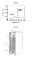
Fig. 1 is a graph showing a differential scanning calorimetry (DSC) measurement result when a cathode material in a charged state and an electrolyte are mixed and temperature is raised. -
Fig. 2 is a partial cross-sectional diagram showing the whole configuration of a lithium ion secondary battery. - The present invention relates to a cathode active material having large capacity, high output, and high safety; a cathode material for a lithium ion secondary battery containing this cathode active material; and a lithium ion secondary battery using this cathode material for a lithium ion secondary battery.
- In order to obtain large capacity in the layer-type cathode material represented by a composition formula of LiMO2 (wherein M is transition metal), it is necessary to increase content of Ni in a transition metal layer.
- However, the cathode material with high Ni content has low structural stability in a charged state compared with other transition metals such as Mn; when temperature of a battery is increased by internal short-circuit or the like, there is a risk, even at relatively low temperature, of leading to ignition and bursting of a battery because oxygen released from the inside of the cathode material reacts with an electrolyte to generate a large exothermic reaction. Here, high Ni content means that the content ofNi is high in the total amount of the transition metal and additive metals M1 and M2.
- Description will be given below on features of the present embodiments.
- Lithium-ion cathode active materials of the present embodiments are represented by a composition formula of LixNiaMnbCocM1 dM2 eO2. In the formula, M1 is at least one or more kinds of elements selected from the group consisting of Al, Ti, and Mg; M2 is at least one or more kinds of elements selected from the group consisting of Mo, W, and Nb; 0.2≤x≤1.2; 0.6≤a≤0.8; 0.05≤b≤0.3; 0.05≤c≤0.3; 0.02≤d≤0.04; 0.02≤e≤0.06; and a+b+c+d+e=1.0.
- Although the cathode active material with high Ni content provides large capacity, it has disadvantages of low storage characteristics and thermal stability in a charged state.
- Accordingly, by suppressing the increase in resistance with adding at least one or more kinds of elements selected from the group consisting of Al, Ti, and Mg, to the cathode active material with high Ni content, storage characteristics in a charged state are improved. Also, by suppressing the amount of generated heat to a low level with adding at least one or more kinds of elements selected from the group consisting of Mo, W, and Nb, thermal stability in a charged state is improved.
- The cathode active materials of the embodiments can significantly reduce the amount of generated heat when temperature is raised together with the electrolyte compared with cathode active materials of high Ni content without additive elements. Therefore, it is capable of reducing a probability of leading to ignition and bursting when the temperature of the battery increases.
- Therefore, by using the cathode active materials of the embodiments the cathode materials for the lithium ion secondary battery and the lithium ion secondary batteries, which reduce the probability of leading to ignition or the like in temperature increase, can be provided.
- Here, the amount of Li in the cathode active materials is 0.2≤x≤1.2. In the case of x<0.2, the amount of Li contained in a Li layer is too low to maintain a layer crystalline structure in a charged state. Also, in the case of 1.2<x, the amounts of transition metals in a complex oxide are decreased and the capacity goes down.
- The amount of Ni is 0.6≤a≤0.8. In the case of a<0.6, the content of Ni mainly contributing to charge-discharge reactions becomes low and the capacity goes down. Also, in the case of a>0.8, the relative content of elements other than Ni is reduced and the thermal stability goes down.
- The amount of Mn is 0.05≤b≤0.3. In the case of b<0.05, a structure in a charged state becomes unstable and temperature of oxygen release from the cathode goes down. Also, in the case of b>0.3, the content ofNi mainly contributing to charge-discharge reactions is decreased and the capacity goes down.
- The amount of Co is 0.05≤c≤0.3. In the case of c<0.05, a structure in a charged state becomes unstable and a volume change of the cathode active material in charging and discharging becomes large. Also, in the case of c>0.3, the content ofNi mainly contributing to charge-discharge reactions is decreased and the capacity goes down.
- The amount of M1 is 0.02≤d≤0.04. In the case of d<0.02, deterioration in storage at high temperature cannot be suppressed. Also, in the case of d>0.04, the content ofNi mainly contributing to charge-discharge reactions is decreased and the capacity goes down.
- The amount of M2 is 0.02≤e≤0.06. In the case of e<0.02, thermal stability in a charged state cannot be secured. Also, in the case of e>0.06, the content ofNi mainly contributing to charge-discharge reactions is decreased and the capacity goes down.
- That is, the lithium ion secondary battery using the cathode active material containing the above-mentioned predetermined amounts of M1 and M2 can suppress deterioration in storing at high temperature and thermal stability in a charged state can be secured.
- As a raw material, oxides containing any one or more kinds of elements among Ni, Mn, Co, M1, and M2 were used and pure water was added to make slurry after weighing so as to attain a predetermined atomic ratio. It should be noted that, as for only M2, the amount of half of the content of an objective composition was used.
- This slurry was pulverized with a zirconia bead mill till an average particle size became 0.2µm. Into this slurry, a solution of polyvinyl alcohol (PVA) was added in 1 wt% as converted to the solid content ratio; it was mixed for further 1 hour and was granulated and dried with a spray dryer. After that, by baking it at 600°C for 20 hours, particles having each element distributed uniformly were obtained. After that, an oxide of M2 equivalent to half the amount of the content of an objective composition pulverized with a bead mill to an average particle size of 0.2 µm was added to the particles. Here wt% is a unit showing the ratio in terms of weight.
- Next, lithium hydroxide and lithium carbonate were added to the particles so as to attain a ratio of Li : (Ni, Mn, Co, M1, and M2), (that is, a ratio of Li against Ni, Mn, Co, M1, and M2) of 1.05: 1 and by baking it at 850°C for 20 hours Cathode
Active Material 1 having a crystal of a layer structure was obtained. - A production method of the cathode active material is not limited to the above method and other methods such as a coprecipitation method may be used.
- Similarly, by using the above production method, Cathode Active Materials 2 to 11 and 14 to 23 were synthesized.
- As for Cathode Active Materials 12 and 13, although the composition ratio (atomic ratio) of metals other than lithium was the same as
Material 1, the ratios of M2 to be added separately in two stages were changed. Here, a value obtained by dividing the content of M2 at the surface part with the content of M2 at the inside of the particles is defined as (content of M2 at the surface part)/(content of M2 at the inside). - Table 1 shows the composition ratios (atomic ratios) of metals other than lithium as for Cathode
Active Materials 1 to 23. - Table 2 shows the content of M2 added in the first stage, the content of M2 added in the second stage, and (content of M2 at the surface part)/(content of M2 at the inside).
- Here, the contents of the elements at the surface and the inside of the particles were measured using an Auger electron spectroscopy. An electron gun was a thermal radiation type and atomic concentrations ofNi, Mn, Co, Al, Mo, and O were measured at conditions of an acceleration voltage of 5.0 kV and a beam current of 90 nA. Conditions of an ion gun were the acceleration voltage of 3.0 kV and ion species of Ar+; a raster size was 3mm×3mm and the depth direction analysis was performed at a sample inclination of 30 degrees. Measurement depth was called in SiO2 equivalent and the content of elements at a depth of 30nm was used to define M2 at the surface and the one at a depth of 300 nm was used to define M2 at the inside.
Table 1 Composition M1 M2 Ni Mn Co Al Ti Mg Mo W Nb Cathode Active material 1 70 5 19 2 - - 4 - - Cathode Active Material 2 80 5 9 2 - - 4 - - Cathode Active Material 3 65 15 14 2 - - 4 - - Cathode Active Material 4 60 15 19 2 - - 4 - - Cathode Active Material 5 70 5 17 4 - - 4 - - Cathode Active Material 6 70 5 21 2 - - 2 - - Cathode Active Material 7 70 5 17 2 - - 6 - - Cathode Active Material 8 70 5 19 - 2 - 4 - - Cathode Active Material 9 70 5 19 - - 2 4 - - Cathode Active Material 10 70 5 19 2 - - - 4 - Cathode Active Material 11 70 5 19 2 - - - - 4 Cathode Active Material 12 70 5 19 2 - - 4 - - Cathode Active Material 13 70 5 19 2 - - 4 - - Cathode Active Material 14 60 20 20 - - - - - - Cathode Active Material 15 50 25 25 - - - - - - Cathode Active Material 16 85 5 5 1 - - 4 - - Cathode Active Material 17 55 19 20 2 - - 4 - - Cathode Active Material 18 70 5 15 6 - - 4 - - Cathode Active Material 19 70 5 22 2 - - 1 - - Cathode Active Material 20 70 5 15 2 - - 8 - - Cathode Active Material 21 70 5 23 2 - - - - - Cathode Active Material 22 70 5 21 - - - 4 - - Cathode Active Material 23 70 5 20 1 - - 4 - - Table 2 Content of Mo Content of M2 to be added in the first stage mixing Content of M2 to be added in the second stage mixing (Content of M2 at the surface part)/(Content of M2 at the inside) Cathode Active Material 1 4 2 2 1.42 Cathode Active Material 12 4 3 1 1.23 Cathode Active Material 13 4 4 0 1.09 - Cathode
Active Material 1 and a carbon-based electric conductor were weighed so as to attain a weight ratio of 85 : 10.7 and they were mixed using a mortar. The mixture of CathodeActive Material 1 and the carbon-based electric conductor and a binding agent dissolved in N-methyl-2-pyrrolidone (NMP) were mixed so as to attain a weight ratio of the mixture and the binding agent of 95.7 : 4.3. - After applying slurry thus mixed homogeneously onto the surface of a foil-like aluminum collector with a thickness of 20µm, it was dried at 120°C and compression-molded with a press so as to attain an electrode density of 2.7×10³kg/m3. After that it was punched out to a circular disk with a diameter of 15mm to produce a cathode.
- The prototype battery was produced using the produced cathode, metal lithium as an anode, and a non-aqueous electrolyte (the one obtained by dissolving LiPF6 at 1.0mol/L in a mixed solvent of ethylene carbonate (EC) and dimethyl carbonate (DMC) at a volume ratio of 1 : 2). Incidentally, other Embodiments 2 to 15 and Comparative Examples 1 to 11 were described later in this description.
- Then, the following tests were performed using the above-described prototype battery.
- Initialization was performed by repeating charge-discharge three times at 0.1C (that is, 0.1 times the current at which a full discharge completes in 1 hour. Similar designations are used hereinafter), the upper limit voltage of 4.3V, and the lower limit voltage of 2.7V Further, charge-discharge was performed at 0.1C, the upper limit voltage of 4.3V, and the lower limit voltage of 2.7V to measure the discharge capacity.
- In
Embodiments - In addition, in
Embodiments 3 and 4 and Comparative Examples 2 and 4, values obtained by dividing the values of the obtained discharge capacities with the value of the discharge capacity of Comparative Example 2 to be described later were defined as capacity ratios. - After charging at constant current/constant voltage up to 4.3V, the cathode was taken out from the prototype battery and washed with DMC. After that, it was punched out to a circular disk with a diameter of 3.5mm, which was put into a sample pan and sealed after adding 1µL (micro liter) of the electrolyte.
- Exothermic behavior was examined when the temperature of this sample was raised from room temperature up to 400°C at a rate of 5°C/min.
- In
Embodiments - In addition, in
Embodiments 3 and 4 and Comparative Examples 2 and 4, values obtained by dividing the obtained amounts of generated heat with the amount of generated heat of Comparative Example 2 to be described later were defined as ratios of the amount of generated heat. - In order to produce a cylinder-type battery, a
cathode plate 1 using the synthesized cathode active material was cut so as to attain an application width of 54mm and an application length of 500mm and a lead strip made of aluminum foil to take out electric current was welded so that the cathode plate was produced. - Next, an anode plate to be combined with this cathode plate was produced.
- By mixing and dissolving a graphite-type carbon material of an anode active material into NMP which already dissolved a binding agent therein, an anode mixture slurry was produced. Then, a dry weight ratio of the amorphous carbon material and the binding agent was set to attain 92 : 8.
- This anode mixture slurry was uniformly applied onto a rolled copper foil with a thickness of 10µm. After that, it was compression-molded using a roll press machine, cut so as to attain an application width of 56mm and an application length of 540mm, and welded with a lead strip made of copper foil to produce an anode plate.
-
Fig. 2 is a cross-sectional view showing a lithium ion secondary battery. - Using the cathode plate and the anode plate produced as described above, a cylinder-type battery shown in the present figure was produced. Explanation will be given on procedures thereof with reference to
Fig. 2 . - First, a
separator 5 was arranged between the cathode plate 3 and theanode plate 4 so that the cathode plate 3 and theanode plate 4 would not contact directly and they were rolled to produce an electrode group. At that time, alead strip 6 of the cathode plate and a lead strip 7 of the anode plate were positioned on the both end faces of mutually opposite sides of the electrode group. Further, caution was paid for an applied part of the cathode mixture not to stick out from an applied part of the anode mixture in the arrangement of the cathode plate 3 and theanode plate 4. In addition, as theseparator 5 used here a microporous polypropylene film with a thickness of 25µm and a width of 58mm was used. - Next, the electrode group was inserted into a battery can 9 made of stainless steel, the anode lead strip 7 was welded to the bottom part of the can, and the
cathode lead strip 6 was welded to aseal lid part 8, which also worked as a cathode current terminal. Into the battery can 9 arranged with this electrode group a non-aqueous electrolyte (the one dissolved LiPF6 at 1.0mol/L into a mixed solvent of ethylene carbonate (EC) and dimethyl carbonate (DMC) in a volume ratio of 1 : 2) was poured and, then, theseal lid part 8 attached with a packing 10 was swaged to the battery can 9 to seal so that the cylinder-type battery with a diameter of 18mm and a length of 65mm was produced. Here, at the seal lid part 8 a cleavage valve was installed for releasing pressure inside the battery by cleaving in the case of pressure increase in the battery and insulatingplates 11 were arranged between theseal lid part 8 and the electrode group and between the bottom part of the battery can 9 and the electrode group. - Next, the following tests were performed using the above-described cylinder-type battery.
- Initialization was performed by repeating charge-discharge three times, at 0.3C, the upper limit voltage of 4.2V, and the lower limit voltage of 2.7V Further, charge-discharge was performed at 0.3C, the upper limit voltage of 4.2V, and the lower limit voltage of 2.7V to measure the battery discharge capacity.
- After performing the charge-discharge test the battery was charged up to a state of charge of 50% and open circuit voltage was measured. Then, a voltage at 10 seconds after starting discharge at a current equivalent to 1C was measured and voltage drop (ΔV) was determined as a difference between them. Further, similar charge-discharge was performed while changing the discharge current condition to equivalent to 3C and equivalent to 6C to measure voltage drops of respective discharge currents (I).
- By plotting these discharge currents (I) and voltage drops (ΔV), resistance of the battery was calculated as a slope thereof. Next, energy output of the battery was determined from the open circuit voltage and resistance of the battery at a battery state of charge of 50%. Further, after storing this battery in a thermostatic vessel held at 50°C in a state of charge of 90% for three months resistance of the battery was measured again. Ratio of increase in battery resistance was defined as a value obtained by dividing the value of battery resistance after storing for three months by that prior to the storage.
- In Embodiments 14 and 15 and Comparative Examples 10 and 11, all to be described later, values obtained by dividing the obtained discharge capacities with the discharge capacity of Comparative Example 9 were defined as capacity ratios and shown in Table 6.
- Also, in Embodiments 14 and 15 and Comparative Examples 10 and 11, values obtained by dividing the obtained ratios of increase in battery resistance with the ratio of increase in battery resistance of Comparative Example 9 were defined as resistance increase ratios and shown in Table 6.
- In addition, an electric conductor, a binding agent, an anode, an electrolyte solvent, and an electrolyte solute, to be used in the prototype batteries and the cylinder-type batteries in the present Embodiments, are not limited to those explained in the present Embodiments and, for example, the following may be used.
- As the electric conductor, graphite, acetylene black, carbon black, or the like may be enumerated.
- As the binding agent, polytetrafluoroethylene, a rubber-type binder, or the like may be enumerated.
- As the anode, a graphite-type carbon material, hard carbon, soft carbon, or the like may be enumerated.
- As the electrolyte solvent, ethylene carbonate, propylene carbonate, dimethyl carbonate, diethyl carbonate, methyl ethyl carbonate, y-butyrolactone, tetrahydrofuran, dimethoxy ethane, or the like may be enumerated.
- As the electrolyte solute, LiBF4, LiClO4, LiAsF6, LiCF3SO3, LiN(CF3SO2)2, or the like may be enumerated.
- In Embodiment 2, a prototype battery was produced in a similar method as in
Embodiment 1 except for using produced Cathode Active Material 2; the charge-discharge test and the differential scanning calorimetry were performed. - In Embodiment 3, a prototype battery was produced in a similar method as in
Embodiment 1 except for using produced Cathode Active Material 3; the charge-discharge test and the differential scanning calorimetry were performed. - In
Embodiment 4, a prototype battery was produced in a similar method as inEmbodiment 1 except for using produced CathodeActive Material 4; the charge-discharge test and the differential scanning calorimetry were performed. - In
Embodiment 5, a prototype battery was produced in a similar method as inEmbodiment 1 except for using produced CathodeActive Material 5; the charge-discharge test and the differential scanning calorimetry were performed. - In
Embodiment 6, a prototype battery was produced in a similar method as inEmbodiment 1 except for using produced CathodeActive Material 6; the charge-discharge test and the differential scanning calorimetry were performed. - In Embodiment 7, a prototype battery was produced in a similar method as in
Embodiment 1 except for using produced Cathode Active Material 7; the charge-discharge test and the differential scanning calorimetry were performed. - In
Embodiment 8, a prototype battery was produced in a similar method as inEmbodiment 1 except for using produced CathodeActive Material 8; the charge-discharge test and the differential scanning calorimetry were performed. - In
Embodiment 9, a prototype battery was produced in a similar method as inEmbodiment 1 except for using produced CathodeActive Material 9; the charge-discharge test and the differential scanning calorimetry were performed. - In
Embodiment 10, a prototype battery was produced in a similar method as inEmbodiment 1 except for using produced CathodeActive Material 10; the charge-discharge test and the differential scanning calorimetry were performed. - In
Embodiment 11, a prototype battery was produced in a similar method as inEmbodiment 1 except for using produced CathodeActive Material 11; the charge-discharge test and the differential scanning calorimetry were performed. - In Embodiment 12, a prototype battery was produced in a similar method as in
Embodiment 1 except for using produced Cathode Active Material 12; the charge-discharge test and the differential scanning calorimetry were performed. - In Embodiment 13, a prototype battery was produced in a similar method as in
Embodiment 1 except for using produced Cathode Active Material 13; the charge-discharge test and the differential scanning calorimetry were performed. - In Embodiment 14, a cylinder-type battery was produced using produced Cathode
Active Material 1 as the cathode. Using the present battery, the charge-discharge test was performed and increase in resistance after storage at high temperature was measured. - In Embodiment 15, a cylinder-type battery was produced using produced Cathode
Active Material 5 as the cathode. Using the present battery, the charge-discharge test was performed and increase in resistance after storage at high temperature was measured. - In Comparative Example 1, a prototype battery was produced in a similar method as in
Embodiment 1 except for using produced Cathode Active Material 14; the charge-discharge test and the differential scanning calorimetry were performed. - In Comparative Example 2, a prototype battery was produced in a similar method as in
Embodiment 1 except for using produced Cathode Active Material 15; the charge-discharge test and the differential scanning calorimetry were performed. - In Comparative Example 3, a prototype battery was produced in a similar method as in
Embodiment 1 except for using produced Cathode Active Material 16; the charge-discharge test and the differential scanning calorimetry were performed. - In Comparative Example 4, a prototype battery was produced in a similar method as in
Embodiment 1 except for using produced Cathode Active Material 17; the charge-discharge test and the differential scanning calorimetry were performed. - In Comparative Example 5, a prototype battery was produced in a similar method as in
Embodiment 1 except for using produced Cathode Active Material 18; the charge-discharge test and the differential scanning calorimetry were performed. - In Comparative Example 6, a prototype battery was produced in a similar method as in
Embodiment 1 except for using produced Cathode Active Material 19; the charge-discharge test and the differential scanning calorimetry were performed. - In Comparative Example 7, a prototype battery was produced in a similar method as in
Embodiment 1 except for using produced Cathode Active Material 20; the charge-discharge test and the differential scanning calorimetry were performed. - In Comparative Example 8, a prototype battery was produced in a similar method as in
Embodiment 1 except for using produced Cathode Active Material 21; the charge-discharge test and the differential scanning calorimetry were performed. - In Comparative Example 9, a cylinder-type battery was produced using produced Cathode Active Material 14 as the cathode. Using the present battery, the charge-discharge test was performed and increase in resistance after storage at high temperature was measured.
- In Comparative Example 10, a cylinder-type battery was produced using produced Cathode Active Material 22 as the cathode. Using the present battery, the charge-discharge test was performed and increase in resistance after storage at high temperature was measured.
- In Comparative Example 11, a cylinder-type battery was produced using produced Cathode Active Material 23 as the cathode. Using the present battery, the charge-discharge test was performed and increase in resistance after storage at high temperature was measured.
- Table 3 shows capacity ratios and ratios of the amount of generated heat of
Embodiments 1 to 11 and Comparative Examples 1 to 8. - Table 4 shows capacity ratios and ratios of the amount of generated heat of
Embodiments 3 and 4 and Comparative Examples 2 and 4. - Table 5 shows capacity ratios and ratios of the amount of generated heat of
Embodiments 1, 12, and 13. - Table 6 shows capacity ratios and resistance ratios of Embodiments 14 and 15 and Comparative Examples 9 to 11.
- From Table 3, in
Embodiments - It is considered that the larger values of discharge capacity were shown because the cathode materials selected in respective Embodiments contained high amounts ofNi in a transition metal layer. In addition, it is considered that the smaller amounts of generated heat were because M2 (Mo, W, and Nb), which enhances thermal stability in a charged state, was contained at 2% or more.
- On the other hand, in Comparative Examples 3 and 5 to 8, it was impossible to attain both enhancement of the discharge capacity and reduction of the amount of generated heat. In Comparative Example 3, because of the high content ofNi of 85%, the amount of generated heat increased. In Comparative Example 5, because of the high content of Al of 6%, the discharge capacity decreased. In Comparative Examples 6 and 8, because of the low content of Mo of 1% and 0%, respectively, enhancement effect of thermal stability was small and the amount of generated heat increased. In Comparative Example 7, because of the high content of Mo of 6%, the discharge capacity decreased.
- From Table 4, in
Embodiments 3 and 4, results of larger discharge capacities and smaller amounts of generated heat were obtained compared with Comparative Example 2. - It is considered that the larger values of discharge capacity were shown because the cathode materials selected in respective Embodiments contained high amounts ofNi in a transition metal layer. In addition, it is considered that the smaller amounts of generated heat were because Mo, which enhances thermal stability in a charged state, existed at 2% or more.
- On the other hand, in Comparative Example 4, it was impossible to attain both enhancement of the discharge capacity and reduction of the amount of generated heat. The reason for decrease in the discharge capacity is the low content of Ni of 55%, which mainly contributes to a charge-discharge reaction.
- From Table 5, in Embodiments 12 and 13, results of larger discharge capacities and smaller amounts of generated heat were obtained compared with Comparative Example 1. However, the ratio of the amount of generated heat increased compared with
Embodiment 1. This is because the lower content of Mo present at the surface part in Embodiments 12 and 13 than inEmbodiment 1. This is because the exothermic reaction between the electrolyte and the cathode which occurs mainly at the surface part of the cathode is suppressed by containing the large amount of Mo, which enhances thermal stability of the cathode, at the surface part. - Accordingly, it is preferable that (content of M2 at the surface part)/(content of M2 at the inside) is at least 1.09 or more. It is still more preferable that (content of M2 at the surface part)/(content of M2 at the inside) is 1.42 or less.
- From Table 6, it is understood that in Embodiments 14 and 15 increases in resistance after storing at high temperature can be suppressed by 5% or more compared with Comparative Example 9.
- On the other hand, in Comparative Examples 10 and 11, it was impossible to attain both enhancement of the discharge capacity and suppression of the increase in resistance after storage at high temperature. This shows that the content of Al was as low as less than 2% and suppression of the increase in resistance was a very low value of 2% or lower. From this result, it is understood that for suppression of the increase in resistance the content of Al is necessary to be 2% or higher.
-
Fig. 1 shows DSC measurement results ofEmbodiment 1 and Comparative Example 1. - In the present figure, with
Embodiment 1 there is no significant exothermic peak. On the contrary, with Comparative Example 1 there is an exothermic peak at around 280°C. - By using the active material shown in the present embodiments for a cathode of a lithium ion secondary battery, there can be provided a cathode material for a lithium ion secondary battery, which is capable of attaining high capacity and high safety required in a battery for a plug-in hybrid automobile.
- It should be further understood by those skilled in the art that although the foregoing description has been made on embodiments of the invention, the invention is not limited thereto and various changes and modifications may be made without departing from the spirit of the invention and the scope of the appended claims.
- The present invention is applicable to a cathode material of a lithium ion secondary battery and is applicable to a lithium ion secondary battery for a plug-in hybrid automobile.
| Capacity Ratio | Ratio of Amount of Generated | |
| Embodiment | ||
| 1 | 1.081 | 0.776 |
| Embodiment 2 | 1.138 | 0.931 |
| Embodiment 3 | 1.040 | 0.924 |
| | 1.013 | 0.983 |
| | 1.025 | 0.755 |
| | 1.106 | 0.988 |
| Embodiment 7 | 1.015 | 0.727 |
| | 1.081 | 0.804 |
| | 1.081 | 0.818 |
| | 1.050 | 0.759 |
| | 1.056 | 0.744 |
| Comparative Example 1 | 1.000 | 1.000 |
| Comparative Example 2 | 1.000 | 1.000 |
| Comparative Example 3 | 1.131 | 1.035 |
| Comparative Example 4 | 0.960 | 0.883 |
| Comparative Example 5 | 0.994 | 0.745 |
| Comparative Example 6 | 1.113 | 1.020 |
| Comparative Example 7 | 0.963 | 0.701 |
| Comparative Example 8 | 1.119 | 1.162 |
| Capacity Ratio | Ratio of Amount of Generated Heat | |
| Embodiment 3 | 1.040 | 0.924 |
| | 1.013 | 0.983 |
| Comparative Example 2 | 1.000 | 1.000 |
| Comparative Example 4 | 0.960 | 0.883 |
| Capacity Ratio | Ratio of Amount of Generated | |
| Embodiment | ||
| 1 | 1.081 | 0.776 |
| Embodiment 12 | 1.083 | 0.781 |
| Embodiment 13 | 1.085 | 0.790 |
| Capacity Ratio | Resistance Increase Ratio | |
| Embodiment 14 | 1.081 | 0.923 |
| Embodiment 15 | 1.024 | 0.889 |
| Comparative Example 9 | 1.000 | 1.000 |
| Comparative Example 10 | 1.105 | 0.989 |
| Comparative Example 11 | 1.093 | 0.981 |
Claims (7)
- A cathode active material (3) represented by a composition formula of LixNiaMnbCocM1 dM2 eO2 where M1 is at least one or more kinds of elements selected from the group consisting of Al, Ti, and Mg; M2 is at least one or more kinds of elements selected from the group consisting of Mo, W, and Nb; 0.2≤x≤1.2; 0.6≤a≤0.8; 0.05≤b≤0.3; 0.05≤c≤0.3; 0.02≤d≤0.04; 0.02≤e≤0.06; and a+b+c+d+e=1.0.
- The cathode active material according to Claim 1, wherein a range of "a" of said formula is 0.7≤a≤0.8.
- The cathode active material according to Claim 1 or 2, wherein a range of "e" of said formula is 0.04≤e≤0.06.
- A cathode material for a lithium ion secondary battery composed of particles comprising the cathode active material according to any one of Claims 1 to 3, wherein concentration of M2 contained in said particles is higher at the surface part of said particles than at the inside of said particles.
- The cathode material for the lithium ion secondary battery according to Claim 4, wherein concentration of M2 contained in said particles satisfies 1.09≤(content of M2 at the surface part)/(content of M2 at the inside).
- The cathode material for the lithium ion secondary battery according to Claim 5, wherein concentration of M2 contained in said particles further satisfies (content of M2 at the surface part)/(content of M2 at the inside)≤1.42.
- A lithium ion secondary battery in which a cathode (3) enabling to store and release lithium and an anode (4) enabling to store and release lithium are arranged via a non-aqueous electrolyte and a separator (5) thereinbetween, wherein said cathode (3) comprises the cathode material for the lithium ion secondary battery according to Claim 4.
Applications Claiming Priority (1)
| Application Number | Priority Date | Filing Date | Title |
|---|---|---|---|
| JP2010148424A JP5421865B2 (en) | 2010-06-30 | 2010-06-30 | Lithium ion secondary battery |
Publications (3)
| Publication Number | Publication Date |
|---|---|
| EP2403039A2 true EP2403039A2 (en) | 2012-01-04 |
| EP2403039A3 EP2403039A3 (en) | 2013-07-24 |
| EP2403039B1 EP2403039B1 (en) | 2014-04-23 |
Family
ID=44503563
Family Applications (1)
| Application Number | Title | Priority Date | Filing Date |
|---|---|---|---|
| EP11172076.9A Not-in-force EP2403039B1 (en) | 2010-06-30 | 2011-06-30 | Lithium ion secondary battery |
Country Status (5)
| Country | Link |
|---|---|
| US (1) | US20120003542A1 (en) |
| EP (1) | EP2403039B1 (en) |
| JP (1) | JP5421865B2 (en) |
| KR (1) | KR101260159B1 (en) |
| CN (1) | CN102315434A (en) |
Cited By (1)
| Publication number | Priority date | Publication date | Assignee | Title |
|---|---|---|---|---|
| EP2518804A1 (en) * | 2011-04-28 | 2012-10-31 | Nichia Corporation | Positive electrode active material for non-aqueous electrolyte secondary battery |
Families Citing this family (12)
| Publication number | Priority date | Publication date | Assignee | Title |
|---|---|---|---|---|
| JP5614513B2 (en) | 2012-08-28 | 2014-10-29 | 住友金属鉱山株式会社 | Method for producing positive electrode active material for non-aqueous electrolyte secondary battery, positive electrode active material for non-aqueous electrolyte secondary battery, and non-aqueous electrolyte secondary battery using the same |
| KR101794097B1 (en) | 2013-07-03 | 2017-11-06 | 삼성에스디아이 주식회사 | Positive active material for rechargeable lithium battery, method of preparing the same, and positive electrode for rechargeable lithium battery and rechargeable lithium battery including the same |
| CN103490051B (en) * | 2013-09-18 | 2015-10-28 | 成都晶元新材料技术有限公司 | One is applicable to high-tension multielement cathode lithium electric material and preparation method thereof |
| US10522830B2 (en) | 2013-11-22 | 2019-12-31 | Sumitomo Metal Mining Co., Ltd. | Positive electrode active material for nonaqueous electrolyte secondary batteries and production method thereof, and nonaqueous electrolyte secondary battery |
| JP6428648B2 (en) * | 2014-01-31 | 2018-11-28 | 三洋電機株式会社 | Positive electrode active material for non-aqueous electrolyte secondary battery, non-aqueous electrolyte secondary battery using the same, and method for producing positive electrode active material for non-aqueous electrolyte secondary battery |
| JP6848181B2 (en) * | 2015-11-27 | 2021-03-24 | 住友金属鉱山株式会社 | Positive electrode active material for non-aqueous electrolyte secondary battery and its manufacturing method, and non-aqueous electrolyte secondary battery |
| KR102004665B1 (en) | 2016-05-30 | 2019-07-26 | 히타치 긴조쿠 가부시키가이샤 | A positive electrode active material for a lithium ion secondary battery, a positive electrode including the positive electrode active material, and a lithium ion secondary battery having the positive electrode |
| KR101918719B1 (en) | 2016-12-12 | 2018-11-14 | 주식회사 포스코 | Positive electrode active material for rechargeable lithium battery, method for manufacturing the same, and rechargeable lithium battery including the same |
| JP6883003B2 (en) * | 2018-06-20 | 2021-06-02 | Jx金属株式会社 | Method for manufacturing positive electrode active material for all-solid-state lithium-ion battery, positive electrode for all-solid-state lithium-ion battery, positive electrode active material for all-solid-state lithium-ion battery and all-solid-state lithium-ion battery |
| JP7099286B2 (en) * | 2018-11-29 | 2022-07-12 | 株式会社豊田自動織機 | Lithium Nickel Cobalt Molybdenum Oxide |
| CN115863571B (en) * | 2022-12-01 | 2025-02-18 | 宁德时代新能源科技股份有限公司 | Positive electrode active material, method for preparing same, secondary battery, and electricity using device |
| CN119330423A (en) * | 2024-10-22 | 2025-01-21 | 格林美(无锡)能源材料有限公司 | A molybdenum and titanium doped single crystal positive electrode material and its preparation method and application |
Citations (4)
| Publication number | Priority date | Publication date | Assignee | Title |
|---|---|---|---|---|
| JP2007018985A (en) | 2005-07-11 | 2007-01-25 | Matsushita Electric Ind Co Ltd | Lithium ion secondary battery |
| JP2007273441A (en) | 2006-03-06 | 2007-10-18 | Sony Corp | Positive electrode active material, method for producing the same, and nonaqueous electrolyte secondary battery |
| JP2008140747A (en) | 2006-12-05 | 2008-06-19 | Sony Corp | Positive electrode active material for non-aqueous electrolyte secondary battery, method for producing the same, and non-aqueous electrolyte secondary battery |
| JP2010073686A (en) | 2008-08-19 | 2010-04-02 | Hitachi Maxell Ltd | Electrode for electrochemical element and nonaqueous secondary battery |
Family Cites Families (13)
| Publication number | Priority date | Publication date | Assignee | Title |
|---|---|---|---|---|
| JP3624663B2 (en) * | 1996-12-24 | 2005-03-02 | 株式会社日立製作所 | battery |
| JP2004303673A (en) * | 2003-04-01 | 2004-10-28 | Hitachi Ltd | Cathode materials for lithium secondary batteries |
| JP4843918B2 (en) * | 2004-08-26 | 2011-12-21 | 新神戸電機株式会社 | Composite oxide material and positive electrode active material for lithium secondary battery |
| KR100822012B1 (en) * | 2006-03-30 | 2008-04-14 | 한양대학교 산학협력단 | Cathode active material for lithium battery, manufacturing method thereof, and lithium secondary battery comprising same |
| US8492030B2 (en) * | 2006-06-19 | 2013-07-23 | Uchicago Argonne Llc | Cathode material for lithium batteries |
| JP4936440B2 (en) * | 2006-10-26 | 2012-05-23 | 日立マクセルエナジー株式会社 | Non-aqueous secondary battery |
| JP5135843B2 (en) * | 2007-03-26 | 2013-02-06 | 三菱化学株式会社 | Lithium transition metal composite oxide, positive electrode for lithium secondary battery using the same, and lithium secondary battery using the same |
| CN101202361A (en) * | 2007-04-24 | 2008-06-18 | 万向集团公司 | Lithium ion battery |
| JP5378720B2 (en) * | 2007-07-27 | 2013-12-25 | パナソニック株式会社 | Lithium ion secondary battery |
| JP2009064602A (en) * | 2007-09-05 | 2009-03-26 | Hitachi Maxell Ltd | Non-aqueous electrolyte secondary battery |
| JP5359140B2 (en) * | 2008-05-01 | 2013-12-04 | 三菱化学株式会社 | Lithium transition metal compound powder, method for producing the same, positive electrode for lithium secondary battery and lithium secondary battery using the same |
| JP5451228B2 (en) * | 2008-07-25 | 2014-03-26 | 三井金属鉱業株式会社 | Lithium transition metal oxide with layer structure |
| JP5695373B2 (en) * | 2009-09-09 | 2015-04-01 | 日立マクセル株式会社 | Electrode for electrochemical element and electrochemical element using the same |
-
2010
- 2010-06-30 JP JP2010148424A patent/JP5421865B2/en not_active Expired - Fee Related
-
2011
- 2011-06-23 CN CN2011101699804A patent/CN102315434A/en active Pending
- 2011-06-29 US US13/171,837 patent/US20120003542A1/en not_active Abandoned
- 2011-06-29 KR KR1020110063522A patent/KR101260159B1/en not_active Expired - Fee Related
- 2011-06-30 EP EP11172076.9A patent/EP2403039B1/en not_active Not-in-force
Patent Citations (4)
| Publication number | Priority date | Publication date | Assignee | Title |
|---|---|---|---|---|
| JP2007018985A (en) | 2005-07-11 | 2007-01-25 | Matsushita Electric Ind Co Ltd | Lithium ion secondary battery |
| JP2007273441A (en) | 2006-03-06 | 2007-10-18 | Sony Corp | Positive electrode active material, method for producing the same, and nonaqueous electrolyte secondary battery |
| JP2008140747A (en) | 2006-12-05 | 2008-06-19 | Sony Corp | Positive electrode active material for non-aqueous electrolyte secondary battery, method for producing the same, and non-aqueous electrolyte secondary battery |
| JP2010073686A (en) | 2008-08-19 | 2010-04-02 | Hitachi Maxell Ltd | Electrode for electrochemical element and nonaqueous secondary battery |
Cited By (1)
| Publication number | Priority date | Publication date | Assignee | Title |
|---|---|---|---|---|
| EP2518804A1 (en) * | 2011-04-28 | 2012-10-31 | Nichia Corporation | Positive electrode active material for non-aqueous electrolyte secondary battery |
Also Published As
| Publication number | Publication date |
|---|---|
| KR20120002466A (en) | 2012-01-05 |
| US20120003542A1 (en) | 2012-01-05 |
| JP5421865B2 (en) | 2014-02-19 |
| KR101260159B1 (en) | 2013-05-06 |
| EP2403039B1 (en) | 2014-04-23 |
| CN102315434A (en) | 2012-01-11 |
| EP2403039A3 (en) | 2013-07-24 |
| JP2012014887A (en) | 2012-01-19 |
Similar Documents
| Publication | Publication Date | Title |
|---|---|---|
| EP2403039B1 (en) | Lithium ion secondary battery | |
| EP1734601B1 (en) | Nonaqueous electrolyte secondary battery | |
| EP1347524B1 (en) | Positive electrode active material and nonaqueous electrolyte secondary cell | |
| US8709656B2 (en) | Cathode material for lithium ion secondary battery and lithium ion secondary battery using it | |
| US6379842B1 (en) | Mixed lithium manganese oxide and lithium nickel cobalt oxide positive electrodes | |
| EP2843748B1 (en) | Method for manufacturing non-aqueous electrolyte secondary cell | |
| US8758941B2 (en) | Positive electrode material for lithium ion secondary battery and lithium ion secondary battery using the same | |
| EP3597604A1 (en) | Positive active material, preparation method thereof and positive electrode plate and lithium-ion secondary battery | |
| JP4798964B2 (en) | Nonaqueous electrolyte secondary battery | |
| JP2002203553A (en) | Cathode active material and non-aqueous electrolyte secondary battery | |
| US20110159172A1 (en) | Method for manufacturing positive electrode of nonaqueous electrolyte secondary battery | |
| KR101739294B1 (en) | Positive electrode for lithium secondary battery and lithium secondary battery comprising the same | |
| US7838151B2 (en) | Non-aqueous electrolyte secondary battery | |
| EP2184798B1 (en) | Anode active material, anode comprising the anode active material, lithium battery comprising the anode, and method of preparing the anode active material. | |
| JP5235307B2 (en) | Nonaqueous electrolyte secondary battery | |
| EP3896760A1 (en) | Cathode active material for lithium secondary battery, and lithium secondary battery comprising same | |
| EP4187630A1 (en) | Cathode for lithium secondary battery and lithium secondary battery including the same | |
| JP4737952B2 (en) | Non-aqueous electrolyte secondary battery | |
| JP2006156234A (en) | Nonaqueous electrolyte secondary battery and its charging method | |
| US12261291B2 (en) | Positive electrode active material for lithium ion secondary battery, method of manufacturing positive electrode active material for lithium ion secondary battery, and lithium ion secondary battery | |
| EP4113663B1 (en) | Positive-electrode active material for non-aqueous electrolyte secondary battery, and non-aqueous electrolyte secondary battery | |
| EP4411851A1 (en) | Positive electrode for secondary battery | |
| EP3955337B1 (en) | Positive electrode for nonaqueous electrolyte secondary battery and nonaqueous electrolyte secondary battery | |
| JP7173275B2 (en) | Positive electrode active material for lithium ion secondary battery, method for producing positive electrode active material for lithium ion secondary battery, lithium ion secondary battery | |
| US20220140337A1 (en) | Positive electrode active material for lithium ion secondary battery, method of manufacturing positive electrode active material for lithium ion secondary battery, and lithium ion secondary battery |
Legal Events
| Date | Code | Title | Description |
|---|---|---|---|
| 17P | Request for examination filed |
Effective date: 20111104 |
|
| AK | Designated contracting states |
Kind code of ref document: A2 Designated state(s): AL AT BE BG CH CY CZ DE DK EE ES FI FR GB GR HR HU IE IS IT LI LT LU LV MC MK MT NL NO PL PT RO RS SE SI SK SM TR |
|
| AX | Request for extension of the european patent |
Extension state: BA ME |
|
| PUAI | Public reference made under article 153(3) epc to a published international application that has entered the european phase |
Free format text: ORIGINAL CODE: 0009012 |
|
| PUAL | Search report despatched |
Free format text: ORIGINAL CODE: 0009013 |
|
| AK | Designated contracting states |
Kind code of ref document: A3 Designated state(s): AL AT BE BG CH CY CZ DE DK EE ES FI FR GB GR HR HU IE IS IT LI LT LU LV MC MK MT NL NO PL PT RO RS SE SI SK SM TR |
|
| AX | Request for extension of the european patent |
Extension state: BA ME |
|
| RIC1 | Information provided on ipc code assigned before grant |
Ipc: H01M 10/0525 20100101AFI20130617BHEP Ipc: H01M 4/485 20100101ALI20130617BHEP Ipc: H01M 4/505 20100101ALI20130617BHEP Ipc: H01M 4/525 20100101ALI20130617BHEP |
|
| REG | Reference to a national code |
Ref country code: DE Ref legal event code: R079 Ref document number: 602011006330 Country of ref document: DE Free format text: PREVIOUS MAIN CLASS: H01M0004131000 Ipc: H01M0010052500 |
|
| GRAP | Despatch of communication of intention to grant a patent |
Free format text: ORIGINAL CODE: EPIDOSNIGR1 |
|
| RIC1 | Information provided on ipc code assigned before grant |
Ipc: H01M 4/485 20100101ALI20130904BHEP Ipc: H01M 4/525 20100101ALI20130904BHEP Ipc: H01M 4/505 20100101ALI20130904BHEP Ipc: H01M 10/0525 20100101AFI20130904BHEP |
|
| INTG | Intention to grant announced |
Effective date: 20130927 |
|
| GRAS | Grant fee paid |
Free format text: ORIGINAL CODE: EPIDOSNIGR3 |
|
| GRAA | (expected) grant |
Free format text: ORIGINAL CODE: 0009210 |
|
| RAP1 | Party data changed (applicant data changed or rights of an application transferred) |
Owner name: HITACHI, LTD. |
|
| AK | Designated contracting states |
Kind code of ref document: B1 Designated state(s): AL AT BE BG CH CY CZ DE DK EE ES FI FR GB GR HR HU IE IS IT LI LT LU LV MC MK MT NL NO PL PT RO RS SE SI SK SM TR |
|
| REG | Reference to a national code |
Ref country code: GB Ref legal event code: FG4D |
|
| REG | Reference to a national code |
Ref country code: CH Ref legal event code: EP |
|
| REG | Reference to a national code |
Ref country code: AT Ref legal event code: REF Ref document number: 664302 Country of ref document: AT Kind code of ref document: T Effective date: 20140515 |
|
| REG | Reference to a national code |
Ref country code: IE Ref legal event code: FG4D |
|
| REG | Reference to a national code |
Ref country code: DE Ref legal event code: R096 Ref document number: 602011006330 Country of ref document: DE Effective date: 20140605 |
|
| REG | Reference to a national code |
Ref country code: AT Ref legal event code: MK05 Ref document number: 664302 Country of ref document: AT Kind code of ref document: T Effective date: 20140423 |
|
| REG | Reference to a national code |
Ref country code: NL Ref legal event code: VDEP Effective date: 20140423 |
|
| REG | Reference to a national code |
Ref country code: LT Ref legal event code: MG4D |
|
| PG25 | Lapsed in a contracting state [announced via postgrant information from national office to epo] |
Ref country code: NO Free format text: LAPSE BECAUSE OF FAILURE TO SUBMIT A TRANSLATION OF THE DESCRIPTION OR TO PAY THE FEE WITHIN THE PRESCRIBED TIME-LIMIT Effective date: 20140723 Ref country code: FI Free format text: LAPSE BECAUSE OF FAILURE TO SUBMIT A TRANSLATION OF THE DESCRIPTION OR TO PAY THE FEE WITHIN THE PRESCRIBED TIME-LIMIT Effective date: 20140423 Ref country code: NL Free format text: LAPSE BECAUSE OF FAILURE TO SUBMIT A TRANSLATION OF THE DESCRIPTION OR TO PAY THE FEE WITHIN THE PRESCRIBED TIME-LIMIT Effective date: 20140423 Ref country code: CY Free format text: LAPSE BECAUSE OF FAILURE TO SUBMIT A TRANSLATION OF THE DESCRIPTION OR TO PAY THE FEE WITHIN THE PRESCRIBED TIME-LIMIT Effective date: 20140423 Ref country code: LT Free format text: LAPSE BECAUSE OF FAILURE TO SUBMIT A TRANSLATION OF THE DESCRIPTION OR TO PAY THE FEE WITHIN THE PRESCRIBED TIME-LIMIT Effective date: 20140423 Ref country code: IS Free format text: LAPSE BECAUSE OF FAILURE TO SUBMIT A TRANSLATION OF THE DESCRIPTION OR TO PAY THE FEE WITHIN THE PRESCRIBED TIME-LIMIT Effective date: 20140823 Ref country code: BG Free format text: LAPSE BECAUSE OF FAILURE TO SUBMIT A TRANSLATION OF THE DESCRIPTION OR TO PAY THE FEE WITHIN THE PRESCRIBED TIME-LIMIT Effective date: 20140723 Ref country code: GR Free format text: LAPSE BECAUSE OF FAILURE TO SUBMIT A TRANSLATION OF THE DESCRIPTION OR TO PAY THE FEE WITHIN THE PRESCRIBED TIME-LIMIT Effective date: 20140724 |
|
| PG25 | Lapsed in a contracting state [announced via postgrant information from national office to epo] |
Ref country code: LV Free format text: LAPSE BECAUSE OF FAILURE TO SUBMIT A TRANSLATION OF THE DESCRIPTION OR TO PAY THE FEE WITHIN THE PRESCRIBED TIME-LIMIT Effective date: 20140423 Ref country code: RS Free format text: LAPSE BECAUSE OF FAILURE TO SUBMIT A TRANSLATION OF THE DESCRIPTION OR TO PAY THE FEE WITHIN THE PRESCRIBED TIME-LIMIT Effective date: 20140423 Ref country code: AT Free format text: LAPSE BECAUSE OF FAILURE TO SUBMIT A TRANSLATION OF THE DESCRIPTION OR TO PAY THE FEE WITHIN THE PRESCRIBED TIME-LIMIT Effective date: 20140423 Ref country code: HR Free format text: LAPSE BECAUSE OF FAILURE TO SUBMIT A TRANSLATION OF THE DESCRIPTION OR TO PAY THE FEE WITHIN THE PRESCRIBED TIME-LIMIT Effective date: 20140423 Ref country code: PL Free format text: LAPSE BECAUSE OF FAILURE TO SUBMIT A TRANSLATION OF THE DESCRIPTION OR TO PAY THE FEE WITHIN THE PRESCRIBED TIME-LIMIT Effective date: 20140423 Ref country code: SE Free format text: LAPSE BECAUSE OF FAILURE TO SUBMIT A TRANSLATION OF THE DESCRIPTION OR TO PAY THE FEE WITHIN THE PRESCRIBED TIME-LIMIT Effective date: 20140423 Ref country code: ES Free format text: LAPSE BECAUSE OF FAILURE TO SUBMIT A TRANSLATION OF THE DESCRIPTION OR TO PAY THE FEE WITHIN THE PRESCRIBED TIME-LIMIT Effective date: 20140423 |
|
| PG25 | Lapsed in a contracting state [announced via postgrant information from national office to epo] |
Ref country code: PT Free format text: LAPSE BECAUSE OF FAILURE TO SUBMIT A TRANSLATION OF THE DESCRIPTION OR TO PAY THE FEE WITHIN THE PRESCRIBED TIME-LIMIT Effective date: 20140825 |
|
| REG | Reference to a national code |
Ref country code: DE Ref legal event code: R097 Ref document number: 602011006330 Country of ref document: DE |
|
| PG25 | Lapsed in a contracting state [announced via postgrant information from national office to epo] |
Ref country code: MC Free format text: LAPSE BECAUSE OF FAILURE TO SUBMIT A TRANSLATION OF THE DESCRIPTION OR TO PAY THE FEE WITHIN THE PRESCRIBED TIME-LIMIT Effective date: 20140423 Ref country code: RO Free format text: LAPSE BECAUSE OF FAILURE TO SUBMIT A TRANSLATION OF THE DESCRIPTION OR TO PAY THE FEE WITHIN THE PRESCRIBED TIME-LIMIT Effective date: 20140423 Ref country code: CZ Free format text: LAPSE BECAUSE OF FAILURE TO SUBMIT A TRANSLATION OF THE DESCRIPTION OR TO PAY THE FEE WITHIN THE PRESCRIBED TIME-LIMIT Effective date: 20140423 Ref country code: SK Free format text: LAPSE BECAUSE OF FAILURE TO SUBMIT A TRANSLATION OF THE DESCRIPTION OR TO PAY THE FEE WITHIN THE PRESCRIBED TIME-LIMIT Effective date: 20140423 Ref country code: BE Free format text: LAPSE BECAUSE OF FAILURE TO SUBMIT A TRANSLATION OF THE DESCRIPTION OR TO PAY THE FEE WITHIN THE PRESCRIBED TIME-LIMIT Effective date: 20140423 Ref country code: DK Free format text: LAPSE BECAUSE OF FAILURE TO SUBMIT A TRANSLATION OF THE DESCRIPTION OR TO PAY THE FEE WITHIN THE PRESCRIBED TIME-LIMIT Effective date: 20140423 Ref country code: EE Free format text: LAPSE BECAUSE OF FAILURE TO SUBMIT A TRANSLATION OF THE DESCRIPTION OR TO PAY THE FEE WITHIN THE PRESCRIBED TIME-LIMIT Effective date: 20140423 Ref country code: LU Free format text: LAPSE BECAUSE OF FAILURE TO SUBMIT A TRANSLATION OF THE DESCRIPTION OR TO PAY THE FEE WITHIN THE PRESCRIBED TIME-LIMIT Effective date: 20140630 |
|
| REG | Reference to a national code |
Ref country code: CH Ref legal event code: PL |
|
| PLBE | No opposition filed within time limit |
Free format text: ORIGINAL CODE: 0009261 |
|
| STAA | Information on the status of an ep patent application or granted ep patent |
Free format text: STATUS: NO OPPOSITION FILED WITHIN TIME LIMIT |
|
| REG | Reference to a national code |
Ref country code: IE Ref legal event code: MM4A |
|
| 26N | No opposition filed |
Effective date: 20150126 |
|
| PG25 | Lapsed in a contracting state [announced via postgrant information from national office to epo] |
Ref country code: LI Free format text: LAPSE BECAUSE OF NON-PAYMENT OF DUE FEES Effective date: 20140630 Ref country code: IE Free format text: LAPSE BECAUSE OF NON-PAYMENT OF DUE FEES Effective date: 20140630 Ref country code: CH Free format text: LAPSE BECAUSE OF NON-PAYMENT OF DUE FEES Effective date: 20140630 |
|
| REG | Reference to a national code |
Ref country code: DE Ref legal event code: R097 Ref document number: 602011006330 Country of ref document: DE Effective date: 20150126 |
|
| PG25 | Lapsed in a contracting state [announced via postgrant information from national office to epo] |
Ref country code: SI Free format text: LAPSE BECAUSE OF FAILURE TO SUBMIT A TRANSLATION OF THE DESCRIPTION OR TO PAY THE FEE WITHIN THE PRESCRIBED TIME-LIMIT Effective date: 20140423 |
|
| PG25 | Lapsed in a contracting state [announced via postgrant information from national office to epo] |
Ref country code: MT Free format text: LAPSE BECAUSE OF FAILURE TO SUBMIT A TRANSLATION OF THE DESCRIPTION OR TO PAY THE FEE WITHIN THE PRESCRIBED TIME-LIMIT Effective date: 20140423 |
|
| PG25 | Lapsed in a contracting state [announced via postgrant information from national office to epo] |
Ref country code: SM Free format text: LAPSE BECAUSE OF FAILURE TO SUBMIT A TRANSLATION OF THE DESCRIPTION OR TO PAY THE FEE WITHIN THE PRESCRIBED TIME-LIMIT Effective date: 20140423 |
|
| REG | Reference to a national code |
Ref country code: FR Ref legal event code: PLFP Year of fee payment: 6 |
|
| PG25 | Lapsed in a contracting state [announced via postgrant information from national office to epo] |
Ref country code: HU Free format text: LAPSE BECAUSE OF FAILURE TO SUBMIT A TRANSLATION OF THE DESCRIPTION OR TO PAY THE FEE WITHIN THE PRESCRIBED TIME-LIMIT; INVALID AB INITIO Effective date: 20110630 Ref country code: TR Free format text: LAPSE BECAUSE OF FAILURE TO SUBMIT A TRANSLATION OF THE DESCRIPTION OR TO PAY THE FEE WITHIN THE PRESCRIBED TIME-LIMIT Effective date: 20140423 |
|
| PGFP | Annual fee paid to national office [announced via postgrant information from national office to epo] |
Ref country code: GB Payment date: 20160629 Year of fee payment: 6 Ref country code: DE Payment date: 20160622 Year of fee payment: 6 |
|
| PGFP | Annual fee paid to national office [announced via postgrant information from national office to epo] |
Ref country code: FR Payment date: 20160516 Year of fee payment: 6 |
|
| PGFP | Annual fee paid to national office [announced via postgrant information from national office to epo] |
Ref country code: IT Payment date: 20160621 Year of fee payment: 6 |
|
| REG | Reference to a national code |
Ref country code: DE Ref legal event code: R119 Ref document number: 602011006330 Country of ref document: DE |
|
| GBPC | Gb: european patent ceased through non-payment of renewal fee |
Effective date: 20170630 |
|
| REG | Reference to a national code |
Ref country code: FR Ref legal event code: ST Effective date: 20180228 |
|
| PG25 | Lapsed in a contracting state [announced via postgrant information from national office to epo] |
Ref country code: GB Free format text: LAPSE BECAUSE OF NON-PAYMENT OF DUE FEES Effective date: 20170630 Ref country code: DE Free format text: LAPSE BECAUSE OF NON-PAYMENT OF DUE FEES Effective date: 20180103 |
|
| PG25 | Lapsed in a contracting state [announced via postgrant information from national office to epo] |
Ref country code: IT Free format text: LAPSE BECAUSE OF NON-PAYMENT OF DUE FEES Effective date: 20170630 Ref country code: FR Free format text: LAPSE BECAUSE OF NON-PAYMENT OF DUE FEES Effective date: 20170630 |
|
| PG25 | Lapsed in a contracting state [announced via postgrant information from national office to epo] |
Ref country code: MK Free format text: LAPSE BECAUSE OF FAILURE TO SUBMIT A TRANSLATION OF THE DESCRIPTION OR TO PAY THE FEE WITHIN THE PRESCRIBED TIME-LIMIT Effective date: 20140423 |
|
| PG25 | Lapsed in a contracting state [announced via postgrant information from national office to epo] |
Ref country code: AL Free format text: LAPSE BECAUSE OF FAILURE TO SUBMIT A TRANSLATION OF THE DESCRIPTION OR TO PAY THE FEE WITHIN THE PRESCRIBED TIME-LIMIT Effective date: 20140423 |