EP2402835A2 - A maximum-power-point tracking device for a solar electric-generation system and a tracking method for the same - Google Patents
A maximum-power-point tracking device for a solar electric-generation system and a tracking method for the same Download PDFInfo
- Publication number
- EP2402835A2 EP2402835A2 EP11171645A EP11171645A EP2402835A2 EP 2402835 A2 EP2402835 A2 EP 2402835A2 EP 11171645 A EP11171645 A EP 11171645A EP 11171645 A EP11171645 A EP 11171645A EP 2402835 A2 EP2402835 A2 EP 2402835A2
- Authority
- EP
- European Patent Office
- Prior art keywords
- output
- value
- solar battery
- current value
- output current
- Prior art date
- Legal status (The legal status is an assumption and is not a legal conclusion. Google has not performed a legal analysis and makes no representation as to the accuracy of the status listed.)
- Granted
Links
Images



Classifications
-
- G—PHYSICS
- G05—CONTROLLING; REGULATING
- G05F—SYSTEMS FOR REGULATING ELECTRIC OR MAGNETIC VARIABLES
- G05F1/00—Automatic systems in which deviations of an electric quantity from one or more predetermined values are detected at the output of the system and fed back to a device within the system to restore the detected quantity to its predetermined value or values, i.e. retroactive systems
- G05F1/66—Regulating electric power
- G05F1/67—Regulating electric power to the maximum power available from a generator, e.g. from solar cell
-
- Y—GENERAL TAGGING OF NEW TECHNOLOGICAL DEVELOPMENTS; GENERAL TAGGING OF CROSS-SECTIONAL TECHNOLOGIES SPANNING OVER SEVERAL SECTIONS OF THE IPC; TECHNICAL SUBJECTS COVERED BY FORMER USPC CROSS-REFERENCE ART COLLECTIONS [XRACs] AND DIGESTS
- Y02—TECHNOLOGIES OR APPLICATIONS FOR MITIGATION OR ADAPTATION AGAINST CLIMATE CHANGE
- Y02E—REDUCTION OF GREENHOUSE GAS [GHG] EMISSIONS, RELATED TO ENERGY GENERATION, TRANSMISSION OR DISTRIBUTION
- Y02E10/00—Energy generation through renewable energy sources
- Y02E10/50—Photovoltaic [PV] energy
- Y02E10/56—Power conversion systems, e.g. maximum power point trackers
Definitions
- the present disclosure relates to solar energy, more particularly to a maximum power point tracking device of solar electric-generation system and tracking method of the same.
- a method for improving the work efficiency of a solar battery may include controlling the solar battery to work in the maximum power point.
- the output voltage may be lower than the open circuit voltage, which may limit the range of the output voltage.
- conventional solar electric-generation systems are unable to simultaneously track a maximum power point and expand an output voltage range of the maximum power point. Thus, the solar energy may be wasted.
- the present disclosure provides a maximum power point tracking device and a tracking method of the same for enlarging the range of the output power of the solar battery when tracking the maximum power point.
- the present disclosure provides a maximum power point tracking device for a solar electric-generation system that includes a solar battery and a DC/DC converter connected to the solar battery.
- the maximum power point tracking device includes a sampling module electronically connected to an output terminal of the solar battery and configured to detect an output current value and a output voltage value of the solar battery.
- the device includes a controlling module connected to the sampling module and configured to: calculate a target current value according to the output current value and the output voltage value of the solar battery and a preset current value; and output a controlling signal for controlling the value of a current according to the output current of the solar battery and the target current value.
- the device also includes a driving module electronically connected to the DC/DC converter and the controlling module.
- the driving module is configured to: receive the controlling signal from the controlling module; and output a driving signal to adjust an output current value of the DC/DC converter close to the target current value, and to adjust an output power of the DC/DC converter.
- the output current is adjusted to the target current value, preferably close to the target current value, i.e. within a predefined adjustment range. In other words, the output current is adjusted towards the target current value. Since it may numerically not be possible to adjust the output current value to exactly the target current value, the output current value is adjusted close to or within a vicinity of the target current value. Preferably, the difference between the target current value and the adjusted output current value is less than 20% of the target current value, more preferably less than 10%, even more preferably less than 5%.
- the present disclosure further provides a method for tracking the maximum power of a solar electric-generation system.
- the method may include detecting an output current and an output voltage of a solar battery, and calculating a target current value according to the output current and the output voltage of the solar battery and a preset current value. And the method may include outputting a controlling signal for adjusting a value of a output current of the solar electric-generation system close to the target current value according to the output current of the solar battery and the preset current value.
- the maximum power point tracking device for the solar electric-generation system and the tracking method for the same provided by the present disclosure may calculate the target current value according to the output current and the output voltage of the solar battery and the preset current value to make the solar battery to work in the maximum power point; and adjust the value of the output voltage of the solar battery according to the DC/DC converter to track a maximum power point and expand an output voltage range of the maximum power point at the same time.
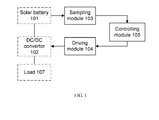
- a maximum-power-point tracking MPPT device for a solar electric-generation system includes a solar battery 101 and a DC/DC converter 102 connected to the solar battery 101.
- the device also includes a sampling module 103 electronically connected to an output terminal of the solar battery 101 and configured to detect an output current value and an output voltage value of the solar battery 101.
- a controlling module 105 is connected to the sampling module 103 and configured to calculate a target current value according to the output current and voltage values of the solar battery 101 and a preset current value, and output a controlling signal according to the output current of the solar battery 101 and the target current value.
- a driving module 104 is electronically connected to the DC/DC converter 102 and the controlling module 105.
- the driving module 104 is configured to receive the controlling signal from the controlling module 105; and output a driving signal to adjust an output current value of the solar battery 101 close to the target current value, and to adjust an output power of the DC/DC converter 102.
- the controlling module 105 may include a MPPT unit 151 connected to the sampling module 103, and a proportional-integral (PI) unit 152 connected to the MPPT unit 151, the sampling module 103 and the driving module 104.
- the MPPT unit 151 is configured to calculate the output power of the solar battery 101 according to the output voltage and the output current of the solar battery 101, and change the output value of the MPPT unit 151 according to the output power and the preset current value.
- the PI unit 152 is configured to calculate the target current value according to the output value of the MPPT unit 151, calculate a duty cycle of the controlling signal according to the target current value and the output current of the solar battery 101, and output the controlling signal for controlling the value of a current.
- the sampling module 103 may include a voltage sensor and a current sensor for detecting the value of the output voltage and the output current of the solar battery 101.
- the DC/DC converter 102 may be a bidirectional DC/DC converter including a first positive terminal U1+, a second positive terminal U2+, a first negative terminal U1- and a second negative terminal U2-.
- the output voltage of the maximum power point of the solar battery 101 may be boosted or bucked via the bidirectional DC/DC converter for expanding the output voltage range of the maximum power point.
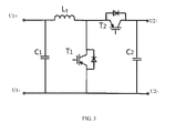
- a bidirectional DC/DC converter may be implemented by a circuit including a first positive terminal U1+ connected to one end of an inductor L1 and one end of a first capacitor C1. Another end of the inductor L1, in turn, is connected to a drain of a first transistor T1 and a source of a second transistor T2. A source of the first transistor T1 and another end of the first capacitor C1 are connected to the first negative terminal U1- and the second negative terminal U2-.
- a drain of the second transistor T2 is connected to the second positive terminal U2+ and one end of a second capacitor C2. Another end of the second capacitor C2 is connected to the first negative terminal U1- and the second negative terminal U2-. And a gate of the first transistor T1 and a gate of the second transistor T2 are connected to the output terminal of the driving module 104.
- the turn-on time of the first transistor T1 and the second transistor T2 may be controlled by a driving signal of the driving module 104. In an instance in which the first transistor T1 is ON, the second transistor T2 is OFF. And in an instance in which the first transistor T1 is OFF, the second transistor T2 is ON.
- the DC/DC converter may boost to the voltage of the solar battery 101 to control the first transistor T1 ON and the second transistor T2 OFF.
- the DC/DC converter may buck to the voltage of the solar battery 101 to control the first transistor T1 ON and the second transistor T2 OFF. This may expand an output voltage range of the maximum power point.
- the present disclosure further provides a method for tracking the maximum power of a solar electric-generation system.
- the method may include detecting an output current and an output voltage of a solar battery 101, and calculating a target current value according to the output current and the output voltage of the solar battery 101 and a preset current value.
- the method may also include outputting a controlling signal for adjusting a value of an output current of the solar electric-generation system close to the target current value according to the output current of the solar battery 101 and the preset current value.
- a tracking method for a solar electric-generation system is also provided according to an example embodiment of the disclosure.
- the tracking method includes setting a preset current value I ⁇ , and outputting a first value M1 and a second M2 according to the preset current value I ⁇ .
- the method includes detecting a value of the output current of the solar battery 101, and processing a first PI adjustment according to the first value M1 and the output current of the solar battery 101 to calculate the duty cycle of the controlling signal for adjusting the output current of the solar electric-generation system close to a first target current value.
- the method includes detecting the output current and the output voltage of the solar battery 101 after the first PI adjustment, and calculating a first output power P1 of the solar battery 101.
- the method includes detecting a value of the output current of the solar battery 101, and processing a second PI adjustment according to the second value M2, the output current of the solar battery 101 and the first target current value to calculate the duty cycle of the controlling signal for adjusting the output current of the solar electric-generation system close to a second target current value.
- the method includes detecting the output current and the output voltage of the solar battery 101 after the second PI adjustment, and calculating a second output power P2 of the solar battery 101.
- the method includes comparing the first output power P1 after the first PI adjustment and the second adjustment, and calculating a third output value M3 according to the comparison result and the preset current value I ⁇ .
- the method includes detecting the value of the output current of the solar battery 101, and processing a third PI treatment according to the third output value M3, the output current of the solar battery 101 and the second target current value to calculate the duty cycle of the controlling signal for adjusting the output current of the solar electric-generation system close to a third target current value.
- the MPPT unit 151 runs a positive disturbance; and in an instance in which the output value of the MPPT unit 151 is negative, the MPPT unit 151 runs a negative disturbance.
- M1 being equal to I ⁇ and M2 being equal to -2I ⁇ may make the positive trend and negative trend of the current in a same range at first, and then exactly track the maximum power point of the solar battery 101 according to a change of the output power of the solar battery 101.
- the output voltage and the output current of the solar battery 101 may be changed in real-time, so the maximum power point of the solar battery 101 may not track exactly in a certain time range.
- the maximum power point current may be detected by disturbance, and the output current of the solar battery 101 may steadily flow in a certain time range by PI adjustment for exactly tracking a maximum power point of the solar battery 101 in the certain time range.
- the turn-on time of the first transistor T1 and/or the second transistor T2 may be controlled by adjusting the duty cycle of the control signal of the control module.
- the value of the output current of the solar battery 101 may be adjusted by adjusting the value of the load of the solar battery 101 for making the output current of the solar battery 101 to keep stable after disturbance.
- example embodiments may also provide a method of PI adjustment.
- this method may include calculating a target current value Io according to the first value M1 and the second M2.
- the method may include calculating the duty cycle of the controlling signal according to Plout.
- the duty cycle may be equal to Plout divided by a constant value K.
- the constant value K may be in the range of 2000-3000, and may vary with the voltage class of the system.
- the constant value K may be limited to less than or equal to 3000. And in an instance in which the calculated value is greater than 3000, the constant value K may be limited to 3000.
- the maximum power point of the solar battery 101 may be variable, and in such instances, only by a ceaseless disturbance, the solar battery 101 may work in the maximum power point.
- the tracking method may include comparing an output power of the solar battery 101 after a positive disturbance, with an output power of the solar battery 101 after a negative disturbance.
- the difference between the output power of the solar battery 101 after the positive disturbance, and the output power of the solar battery 101 after the negative disturbance is relatively large.
- a speed of the adjustment to the target current value in the third PI adjustment is relatively fast, and the current value obtained by the third PI adjustment is relatively large.
- the difference between the output power of the solar battery 101 after positive disturbance, and the output power of the solar battery 101 after negative disturbance is relatively small.
- a speed of the adjustment of the target current value of the third PI adjustment is relatively slow, and the current value obtained by the third PI adjustment is relatively small. This may reduce the tracking time early in tracking the maximum power, and increase the tracking stability later in tracking maximum power. And the stable maximum power may be outputted by the third PI adjustment.
- a small disturbance may cause large power change, so the difference between the two disturbances may increase and cause the target current value Io of the third PI adjustment to increase fast.
- a small disturbance may cause a small power change, so the difference between the two disturbances may decrease and cause the target current value Io of the third PI adjustment to increase slowly.
- the DC/DC converter may steadily work in the maximum power point.
- the step F of the tracking method may include setting the third output value M3 equal to I ⁇ + k * abs(P2-P1) in an instance in which P1 is greater than P2, or setting the third output value M3 equal to I ⁇ - k * abs(P2-P1) in an instance in which P1 is less than or equal to P2.
- k is a coefficient whose values range from 0 to 1
- abs (P2-P1) refers to the absolute of the difference.
- FIG. 6 illustrates a tracking method for solar electric generation according to another example embodiment of the disclosure.
- the method includes system initialization and setting a preset current value I ⁇ .
- the first reference value t1, the second reference value t2 and the third reference value t3 of one example are about 1 second.
- the values of the first reference value t1, the second reference value t2 and the third reference value t3 are changeable. In an instance in which the values are too small, the computational complexity of the control module may be increased; or in an instance in which the values are too large, the solar battery 101 may not be adjusted to work in the maximum power point.
- the target current value Io may be cumulatively calculated.
- Kp may be a proportional coefficient
- Ki may be an integral coefficient
- the value range of Kp and Ki may be known to the person skilled in the art.
Landscapes
- Engineering & Computer Science (AREA)
- Life Sciences & Earth Sciences (AREA)
- Sustainable Development (AREA)
- Sustainable Energy (AREA)
- Power Engineering (AREA)
- Physics & Mathematics (AREA)
- Electromagnetism (AREA)
- General Physics & Mathematics (AREA)
- Radar, Positioning & Navigation (AREA)
- Automation & Control Theory (AREA)
- Control Of Electrical Variables (AREA)
Abstract
Description
- The present disclosure relates to solar energy, more particularly to a maximum power point tracking device of solar electric-generation system and tracking method of the same.
- As is generally known, solar energy has reduced pollution and is readily available. But the conversion efficiency of solar batteries is too low, which may lead to the desirability of tracking the maximum power point. The output power of a solar battery is responsive to sunshine intensity and sunshine temperature, and for certain sunshine intensity and sunshine temperature, the maximum power outputted by the solar battery is definite. Thus, a method for improving the work efficiency of a solar battery may include controlling the solar battery to work in the maximum power point. In an instance in which the solar battery works on the maximum power point, the output voltage may be lower than the open circuit voltage, which may limit the range of the output voltage. At present, conventional solar electric-generation systems are unable to simultaneously track a maximum power point and expand an output voltage range of the maximum power point. Thus, the solar energy may be wasted.
- The present disclosure provides a maximum power point tracking device and a tracking method of the same for enlarging the range of the output power of the solar battery when tracking the maximum power point.
- The present disclosure provides a maximum power point tracking device for a solar electric-generation system that includes a solar battery and a DC/DC converter connected to the solar battery. The maximum power point tracking device includes a sampling module electronically connected to an output terminal of the solar battery and configured to detect an output current value and a output voltage value of the solar battery. The device includes a controlling module connected to the sampling module and configured to: calculate a target current value according to the output current value and the output voltage value of the solar battery and a preset current value; and output a controlling signal for controlling the value of a current according to the output current of the solar battery and the target current value. The device also includes a driving module electronically connected to the DC/DC converter and the controlling module. The driving module is configured to: receive the controlling signal from the controlling module; and output a driving signal to adjust an output current value of the DC/DC converter close to the target current value, and to adjust an output power of the DC/DC converter.
- The output current is adjusted to the target current value, preferably close to the target current value, i.e. within a predefined adjustment range. In other words, the output current is adjusted towards the target current value. Since it may numerically not be possible to adjust the output current value to exactly the target current value, the output current value is adjusted close to or within a vicinity of the target current value. Preferably, the difference between the target current value and the adjusted output current value is less than 20% of the target current value, more preferably less than 10%, even more preferably less than 5%.
- The present disclosure further provides a method for tracking the maximum power of a solar electric-generation system. The method may include detecting an output current and an output voltage of a solar battery, and calculating a target current value according to the output current and the output voltage of the solar battery and a preset current value. And the method may include outputting a controlling signal for adjusting a value of a output current of the solar electric-generation system close to the target current value according to the output current of the solar battery and the preset current value.
- The maximum power point tracking device for the solar electric-generation system and the tracking method for the same provided by the present disclosure may calculate the target current value according to the output current and the output voltage of the solar battery and the preset current value to make the solar battery to work in the maximum power point; and adjust the value of the output voltage of the solar battery according to the DC/DC converter to track a maximum power point and expand an output voltage range of the maximum power point at the same time.
- Having thus described example embodiments of the present disclosure in general terms, reference will now be made to the accompanying drawings, which are not necessarily drawn to scale, and wherein:
-
FIG. 1 is a structure diagram of a maximum power point tracking device for a solar electric-generation system according to an example embodiment of the disclosure; -
FIG. 2 is a structure diagram of a maximum power point tracking device for a solar electric-generation system according to an example embodiment of the disclosure; -
FIG. 3 is a circuit diagram of a DC/DC converter according to an example embodiment of the disclosure; -
FIG. 4 is a flow diagram of a tracking method for a solar electric-generation system according to an example embodiment of the disclosure; -
FIG. 5 is a flow diagram of a PI (proportional-integral) adjustment method according to an example embodiment of the disclosure; and -
FIG. 6 is a flow diagram of a tracking method for a solar electric-generation system according to another example embodiment of the disclosure. - The present disclosure now will be described more fully with reference to the accompanying drawings, in which some, but not all embodiments of the disclosure are shown. This disclosure may be embodied in many different forms and should not be construed as limited to the embodiments set forth. Like numbers refer to like elements throughout.Terms such as "substantially," "about," "nearly," "approximately" or the like as used in referring to a relationship between two objects or values are intended to reflect not only an exact relationship but also variances in that relationship that may be due to various factors such as common or accepted error tolerances, variations or the like. It should further be understood that although some values or other relationships may be expressed herein without a modifier, these values or other relationships may also be exact or may include a degree of variation due to various factors such as common or accepted error tolerances, risk tolerances, variations or the like.
- As shown in
FIG. 1 , according to an example embodiment of the present disclosure, a maximum-power-point tracking MPPT device for a solar electric-generation system is provided. As shown, the device includes asolar battery 101 and a DC/DC converter 102 connected to thesolar battery 101. The device also includes asampling module 103 electronically connected to an output terminal of thesolar battery 101 and configured to detect an output current value and an output voltage value of thesolar battery 101. A controllingmodule 105 is connected to thesampling module 103 and configured to calculate a target current value according to the output current and voltage values of thesolar battery 101 and a preset current value, and output a controlling signal according to the output current of thesolar battery 101 and the target current value. Adriving module 104 is electronically connected to the DC/DC converter 102 and the controllingmodule 105. Thedriving module 104 is configured to receive the controlling signal from the controllingmodule 105; and output a driving signal to adjust an output current value of thesolar battery 101 close to the target current value, and to adjust an output power of the DC/DC converter 102. - As shown in
FIG. 2 , according to an example embodiment of the present disclosure, the controllingmodule 105 may include aMPPT unit 151 connected to thesampling module 103, and a proportional-integral (PI)unit 152 connected to theMPPT unit 151, thesampling module 103 and thedriving module 104. TheMPPT unit 151 is configured to calculate the output power of thesolar battery 101 according to the output voltage and the output current of thesolar battery 101, and change the output value of theMPPT unit 151 according to the output power and the preset current value. ThePI unit 152 is configured to calculate the target current value according to the output value of theMPPT unit 151, calculate a duty cycle of the controlling signal according to the target current value and the output current of thesolar battery 101, and output the controlling signal for controlling the value of a current. - The
sampling module 103 may include a voltage sensor and a current sensor for detecting the value of the output voltage and the output current of thesolar battery 101. - The DC/
DC converter 102 may be a bidirectional DC/DC converter including a first positive terminal U1+, a second positive terminal U2+, a first negative terminal U1- and a second negative terminal U2-. The output voltage of the maximum power point of thesolar battery 101 may be boosted or bucked via the bidirectional DC/DC converter for expanding the output voltage range of the maximum power point. - As shown in
FIG. 3 , according an example embodiment of the present disclosure, a bidirectional DC/DC converter may be implemented by a circuit including a first positive terminal U1+ connected to one end of an inductor L1 and one end of a first capacitor C1. Another end of the inductor L1, in turn, is connected to a drain of a first transistor T1 and a source of a second transistor T2. A source of the first transistor T1 and another end of the first capacitor C1 are connected to the first negative terminal U1- and the second negative terminal U2-. - As also shown in
FIG. 3 , a drain of the second transistor T2 is connected to the second positive terminal U2+ and one end of a second capacitor C2. Another end of the second capacitor C2 is connected to the first negative terminal U1- and the second negative terminal U2-. And a gate of the first transistor T1 and a gate of the second transistor T2 are connected to the output terminal of thedriving module 104. In operation, the turn-on time of the first transistor T1 and the second transistor T2 may be controlled by a driving signal of thedriving module 104. In an instance in which the first transistor T1 is ON, the second transistor T2 is OFF. And in an instance in which the first transistor T1 is OFF, the second transistor T2 is ON. - In an instance in which the first positive terminal U1+ and the first negative terminal U1- of the DC/
DC converter 102 are connected to the solar battery (101), and the second positive terminal U2+ and the second negative terminal U2- of the DC/DC converter 102 are connected to aload 107, the DC/DC converter may boost to the voltage of thesolar battery 101 to control the first transistor T1 ON and the second transistor T2 OFF. In an instance in which the second positive terminal U2+ and the second negative terminal U2- of the DC/DC converter 102 are connected to thesolar battery 101, and the first positive terminal U1+ and the first negative terminal U1- of the DC/DC converter 102 are connected to aload 107, the DC/DC converter may buck to the voltage of thesolar battery 101 to control the first transistor T1 ON and the second transistor T2 OFF. This may expand an output voltage range of the maximum power point. - The present disclosure further provides a method for tracking the maximum power of a solar electric-generation system. The method may include detecting an output current and an output voltage of a
solar battery 101, and calculating a target current value according to the output current and the output voltage of thesolar battery 101 and a preset current value. The method may also include outputting a controlling signal for adjusting a value of an output current of the solar electric-generation system close to the target current value according to the output current of thesolar battery 101 and the preset current value. - As shown in
FIG. 4 , a tracking method for a solar electric-generation system is also provided according to an example embodiment of the disclosure. As shown at step A), the tracking method includes setting a preset current value IΔ, and outputting a first value M1 and a second M2 according to the preset current value IΔ. At step B), the method includes detecting a value of the output current of thesolar battery 101, and processing a first PI adjustment according to the first value M1 and the output current of thesolar battery 101 to calculate the duty cycle of the controlling signal for adjusting the output current of the solar electric-generation system close to a first target current value. - At step C), the method includes detecting the output current and the output voltage of the
solar battery 101 after the first PI adjustment, and calculating a first output power P1 of thesolar battery 101. - At step D), the method includes detecting a value of the output current of the
solar battery 101, and processing a second PI adjustment according to the second value M2, the output current of thesolar battery 101 and the first target current value to calculate the duty cycle of the controlling signal for adjusting the output current of the solar electric-generation system close to a second target current value. - At step E), the method includes detecting the output current and the output voltage of the
solar battery 101 after the second PI adjustment, and calculating a second output power P2 of thesolar battery 101. - At step F), the method includes comparing the first output power P1 after the first PI adjustment and the second adjustment, and calculating a third output value M3 according to the comparison result and the preset current value IΔ.
- And at step G), the method includes detecting the value of the output current of the
solar battery 101, and processing a third PI treatment according to the third output value M3, the output current of thesolar battery 101 and the second target current value to calculate the duty cycle of the controlling signal for adjusting the output current of the solar electric-generation system close to a third target current value. - In an instance in which the output value of the
MPPT unit 151 is positive, theMPPT unit 151 runs a positive disturbance; and in an instance in which the output value of theMPPT unit 151 is negative, theMPPT unit 151 runs a negative disturbance. In the tracking method, M1 = IΔ and M2 = -2IΔ. This may ensure that the amplitude of the positive disturbance is equal to the amplitude of the negative disturbance. In other terms, M1 being equal to IΔ and M2 being equal to -2IΔ may make the positive trend and negative trend of the current in a same range at first, and then exactly track the maximum power point of thesolar battery 101 according to a change of the output power of thesolar battery 101. Conversely, the tracking method may run a negative disturbance at first, and then run a positive disturbance, where accordingly, M1 = -IΔ and M2 = 2IΔ. - Generally, the output voltage and the output current of the
solar battery 101 may be changed in real-time, so the maximum power point of thesolar battery 101 may not track exactly in a certain time range. In the present disclosure, the maximum power point current may be detected by disturbance, and the output current of thesolar battery 101 may steadily flow in a certain time range by PI adjustment for exactly tracking a maximum power point of thesolar battery 101 in the certain time range. In other terms, the turn-on time of the first transistor T1 and/or the second transistor T2 may be controlled by adjusting the duty cycle of the control signal of the control module. In this regard, the value of the output current of thesolar battery 101 may be adjusted by adjusting the value of the load of thesolar battery 101 for making the output current of thesolar battery 101 to keep stable after disturbance. - As shown in
FIG. 5 , example embodiments may also provide a method of PI adjustment. As shown, this method may include calculating a target current value Io according to the first value M1 and the second M2. The method may also include calculating an input value Plin of the PI adjustment according to the target current value Io and the output current Iin of thesolar battery 101, where Plin = Io - Iin. In addition, the method may include calculating a proportional PIper and an integration Plsum of the PI adjustment according to the input value Plin, where PIper = Plin * Kp, Plsum = Plin * Ki. The method may include calculating an output value Plout of the PI adjustment according to the PIper and the Plsum, where Plout = Plin + Plsum. And the method may include calculating the duty cycle of the controlling signal according to Plout. - In the PI adjustment method, the duty cycle may be equal to Plout divided by a constant value K. The constant value K may be in the range of 2000-3000, and may vary with the voltage class of the system. When Plout is calculated, the constant value K may be limited to less than or equal to 3000. And in an instance in which the calculated value is greater than 3000, the constant value K may be limited to 3000.
- The maximum power point of the
solar battery 101 may be variable, and in such instances, only by a ceaseless disturbance, thesolar battery 101 may work in the maximum power point. The tracking method may include comparing an output power of thesolar battery 101 after a positive disturbance, with an output power of thesolar battery 101 after a negative disturbance. In one instance, the difference between the output power of thesolar battery 101 after the positive disturbance, and the output power of thesolar battery 101 after the negative disturbance, is relatively large. In this instance, a speed of the adjustment to the target current value in the third PI adjustment is relatively fast, and the current value obtained by the third PI adjustment is relatively large. Conversely, in another instance, the difference between the output power of thesolar battery 101 after positive disturbance, and the output power of thesolar battery 101 after negative disturbance, is relatively small. In this other instance, a speed of the adjustment of the target current value of the third PI adjustment is relatively slow, and the current value obtained by the third PI adjustment is relatively small. This may reduce the tracking time early in tracking the maximum power, and increase the tracking stability later in tracking maximum power. And the stable maximum power may be outputted by the third PI adjustment. - The effect of the first PI adjustment and the second PI adjustment may be disturbance, so the step size of the first PI adjustment and the second PI adjustment may be small, for example, IΔ = 3 Amps. Early in the PI adjustment, a small disturbance may cause large power change, so the difference between the two disturbances may increase and cause the target current value Io of the third PI adjustment to increase fast. Later in the PI adjustment, a small disturbance may cause a small power change, so the difference between the two disturbances may decrease and cause the target current value Io of the third PI adjustment to increase slowly.
- In an instance in which the output power of the
solar battery 101 after positive disturbance is equal to the output power of thesolar battery 101 after negative disturbance, the DC/DC converter may steadily work in the maximum power point. Thus, the step F of the tracking method may include setting the third output value M3 equal to IΔ + k * abs(P2-P1) in an instance in which P1 is greater than P2, or setting the third output value M3 equal to IΔ - k * abs(P2-P1) in an instance in which P1 is less than or equal to P2. In the preceding, k is a coefficient whose values range from 0 to 1, and abs (P2-P1) refers to the absolute of the difference. - Reference is now made to
FIG. 6 , which illustrates a tracking method for solar electric generation according to another example embodiment of the disclosure. As shown atsteps step 03, the method includesMPPT unit 151 running a positive disturbance, and thereafter calculating an output value M1 = IΔ. - At
step 04, the method includes calculating a target current value I1o according to M1, where I1o = M1 + I0o, and I0o is a initial target current value, which is preferably zero. - At
step 05, the method includes detecting a present output current of thesolar battery 101 I1in; and atstep 06, the method includes calculating an input value PI1in of the PI adjustment according to the target current value I1o and the output current I1in of thesolar battery 101, where PI1in = I1o - I1in. - At
step 07, the method includes running a PI adjustment, calculating a proportional PIper and an integration Plsum of the PI adjustment according to the input value Plin, and calculating an output value Plout of the PI adjustment according to the PIper and the Plsum, where PIper = Plin * Kp, Plsum = Plin * Ki and Plout = Plin + Plsum. - At
step 08, the method includes calculating the duty cycle of the controlling signal according to Plout for adjusting the output current of thesolar battery 101 close to the I1o; and atstep 09, the method includes judging whether the time lapsed exceeds a first reference value t1 or not. If not, return to step 05, and if yes, enterstep 10. Atstep 10, then, the method includes recording an initial value I0o of the present target current value, where I0o = I1o. - At
step 11, the method includes detecting a present output current I1in of thesolar battery 101 and a present output voltage U1in of thesolar battery 101; and atstep 12, the method includes calculating and recording a present output power P1 of thesolar battery 101, where P1 = I1in * U1 in. - At
step 13, the method includes theMPPT unit 151 running a negative disturbance, and thereafter calculating an output value M2 = -2IΔ. - At
step 14, the method includes calculating a target current value I2o according to M2; wherein I2o = M2 + I0o. - At
step 15, the method includes detecting a present output current of thesolar battery 101 I2in; and atstep 16, the method includes calculating an input value Plin of the PI adjustment according to the target current value I2o and the output current I2in of thesolar battery 101, wherein Plin = I2o - I2in. - At
step 17, the method includes running a PI adjustment, calculating a proportional PIper and an integration Plsum of the PI adjustment according to the input value Plin, calculating an output value Plout of the PI adjustment according to the PIper and the Plsum, where PIper = Plin * Kp, Plsum = Plin * Ki and Plout = Plin + Plsum. - At
step 18, the method includes calculating the duty cycle of the controlling signal according to Plout for adjusting the output current of thesolar battery 101 close to the I2o; and atstep 19, the method includes judging whether the time lapsed exceeds a second reference value t2 or not. If not, return to step 15; but if yes, enterstep 20. Atstep 20, then, the method includes recording an initial value I0o of the present target current value, where I0o = I2o. - At
step 21, the method includes detecting a present output current I2in of thesolar battery 101 and a present output voltage U2in of thesolar battery 101; and atstep 22, the method includes calculating and recording a present output power P2 of thesolar battery 101, where P2 = I2in * U2in. - At
step 23, the method includes comparing whether P2 is greater than P1. If yes, then enterstep 24; but if not, enterstep 25. Atsteps step 24, M3 = IΔ- k * abs(P2 - P1); and atstep 25, M3 = IΔ + k * abs(P2 - P1). After either step, the method may then proceed to step 26. - At
step 26, the method includes calculating a target current value I3o according to M2; where I3o = M3 + I0o. - At
step 27, the method includes detecting a present output current of thesolar battery 101, I3in; and atstep 28, the method includes calculating an input value Plin of the PI adjustment according to the target current value I3o and the output current I3in of thesolar battery 101, where Plin = I3o - I3in. - At
step 29, the method includes running PI adjustment, calculating a proportional PIper and an integration Plsum of the PI adjustment according to the input value Plin, calculating an output value Plout of the PI adjustment according to the PIper and the Plsum, where PIper = Plin * Kp, Plsum = Plin * Ki and Plout = Plin + Plsum. - At
step 30, the method includes calculating the duty cycle of the controlling signal according to Plout for adjusting the output current of thesolar battery 101 close to the I3o; and atstep 31, the method includes judging whether the time lapsed exceeds a third reference value t3 or not. If not, return to step 27; but if yes, enterstep 32. Atstep 32, then, the method includes recording an initial value I0o of the present target current value, and returningstep 02, where I0o = I3o. - In the above mentioned steps, the first reference value t1, the second reference value t2 and the third reference value t3 of one example are about 1 second. The values of the first reference value t1, the second reference value t2 and the third reference value t3 are changeable. In an instance in which the values are too small, the computational complexity of the control module may be increased; or in an instance in which the values are too large, the
solar battery 101 may not be adjusted to work in the maximum power point. - Also in the above mentioned steps, the target current value Io may be cumulatively calculated. For example, in
step 04, I1o = M1+ I0o, so I1o = IΔ+ I0o, where I0o = 0, so I1o = IΔ. Also, for example, in thestep 14, I20 = I0o + M2, M2 = -2IΔ, so I2o = -2IΔ + I0o, where I0o = I1o = IΔ, so I2o = -IΔ. And in thestep 26, for example, I3o = I0o + M3, M3 = IΔ - k * abs(P2-P1) or M3 = IΔ + k * abs(P2 - P1), so I3o = I0o + IΔ - k * abs(P2 - P1) or I3o = I0o + IΔ + k * abs(P2 - P1), where I0o = I2o = -IΔ, so I3o = -k * abs(P2 - P1) or I3o = k * abs(P2 - P1). - Even further, in
step 07, Kp may be a proportional coefficient, Ki may be an integral coefficient, and the value range of Kp and Ki may be known to the person skilled in the art. - Many modifications and other embodiments set forth herein will come to mind to one skilled in the art to which these example embodiments pertain having the benefit of the teachings presented in the foregoing descriptions and the associated drawings. Therefore, it is to be understood that the embodiments are not to be limited to the specific ones disclosed. Although specific terms are employed herein, they are used in a generic and descriptive sense only and not for purposes of limitation.
Claims (10)
- A maximum-power-point tracking device for a solar electric-generation system that includes a solar battery (101) and a DC/DC converter (102) connected to the solar battery (101), the maximum-power-point tracking device comprising:a sampling module (103) electronically connected to an output terminal of the solar battery (101) and configured to detect an output current value and a output voltage value of the solar battery (101);a controlling module (105) connected to the sampling module (103) and configured to:calculate a target current value according to the output current value and the output voltage value of the solar battery (101) and a preset current value; andoutput a controlling signal for controlling the value of a current according to the output current of the solar battery (101) and the target current value;anda driving module (104) electronically connected to the DC/DC converter (102) and the controlling module (105), wherein the driving module (104) is configured to:receive the controlling signal from the controlling module (105); andoutput a driving signal to the DC/DC converter (102) to adjust an output current value of the solar battery (101) close to the target current value, and to adjust an output power of the DC/DC converter (102).
- The maximum-power-point tracking device of claim 1, wherein the controlling module (105) is further configured to:calculate the target current value according to the output current and output voltage of the solar battery (101);calculate a duty cycle of the controlling signal according to the target current value and the output current value of the solar battery (101); andoutput the controlling signal for controlling the output current of the solar battery (101) close to the target current value.
- The maximum-power-point tracking device of claim 1 or 2, wherein the DC/DC converter (102) of the solar electric-generation system is a bidirectional DC/DC converter (102) including a first positive terminal, a second positive terminal, a first negative terminal and a second negative terminal.
- The maximum-power-point tracking device of claim 3, wherein the first positive terminal and the first negative terminal of the DC/DC converter (102) are connected to the solar battery (101), and the second positive terminal and the second negative terminal of the DC/DC converter (102) are connected to a load.
- The maximum-power-point tracking device of claim 3, wherein the second positive terminal and the second negative terminal of the DC/DC converter (102) are connected to the solar battery (101), and the first positive terminal and the first negative terminal of the DC/DC converter (102) are connected to a load.
- A method for tracking the maximum power of a solar electric-generation system, the method comprising:detecting an output current and an output voltage of a solar battery (101);calculating a target current value according to the output current and the output voltage of the solar battery (101) and a preset current value; andoutputting a controlling signal for adjusting a value of a output current of the solar electric-generation system close to the target current value according to the output current of the solar battery (101) and the preset current value.
- The method of claim 6, further comprising:setting a preset current value IΔ, and outputting a first value M1 and a second M2 according to the preset current value IΔ;detecting a value of the output current of the solar battery (101), and processing a first proportional-integral PI adjustment according to the first value M1 and the output current of the solar battery (101) to calculate the duty cycle of the controlling signal for adjusting the output current of the solar electric-generation system close to a first target current value;detecting the output current and the output voltage of the solar battery (101) after the first PI adjustment, and calculating a first output power P1 of the solar battery (101);detecting a value of the output current of the solar battery (101), and processing a second PI adjustment according to the second value M2, the output current of the solar battery (101) and the first target current value to calculate the duty cycle of the controlling signal for adjusting the output current of the solar electric-generation system close to a second target current value;detecting the output current and the output voltage of the solar battery (101) after the second PI adjustment, and calculating a second output power P2 of the solar battery (101);comparing the first output power P1 after the first PI adjustment and the second adjustment, and calculating a third output value M3 according to according to the comparison result and the preset current value IΔ; anddetecting the value of the output current of the solar battery (101), processing a third PI adjustment according to the third output value M3, the output current of the solar battery (101) and the second target current value to calculate the duty cycle of the controlling signal for adjusting the output current of the solar electric-generation system close to a third target current value.
- The method of claim 7, wherein M1= IΔ and M2=-2IΔ.
- The method of claim 7 or 8, wherein the first PI adjustment, the second PI adjustment or the third PI adjustment comprises:calculating a target current value Io according to the first value M1 and the second M2;calculating an input value Plin of the PI adjustment according to the target current value Io and the output current lin of the solar battery (101), wherein Plin = Io - Iin;calculating a proportional PIper and an integration Plsum of the PI adjustment according to the input value Plin, wherein PIper = Plin * Kp, Plsum = Plin * Ki;calculating an output value Plout of the PI adjustment according to the PIper and the Plsum, wherein Plout = Plin + Plsum; andcalculating the duty cycle of the controlling signal according to Plout.
- The method of one of claims 7 to 9, wherein calculating the third output value M3 includes:setting the third output value M3 equal to IΔ+ k * abs(P2 - P1) in an instance in which P1 is greater than P2, wherein k is a coefficient and values range from 0 to 1; orsetting the third output value M3 equal to IΔ- k * abs(P2 - P1) in an instance in which P1 is less than or equal to P2.
Applications Claiming Priority (1)
| Application Number | Priority Date | Filing Date | Title |
|---|---|---|---|
| CN201010219102.4A CN102315792B (en) | 2010-06-30 | 2010-06-30 | Maximum power tracking device and tracking method of solar power generation system |
Publications (3)
| Publication Number | Publication Date |
|---|---|
| EP2402835A2 true EP2402835A2 (en) | 2012-01-04 |
| EP2402835A3 EP2402835A3 (en) | 2012-05-30 |
| EP2402835B1 EP2402835B1 (en) | 2019-08-07 |
Family
ID=44834979
Family Applications (1)
| Application Number | Title | Priority Date | Filing Date |
|---|---|---|---|
| EP11171645.2A Active EP2402835B1 (en) | 2010-06-30 | 2011-06-28 | A maximum-power-point tracking device for a solar electric-generation system and a tracking method for the same |
Country Status (2)
| Country | Link |
|---|---|
| EP (1) | EP2402835B1 (en) |
| CN (1) | CN102315792B (en) |
Cited By (4)
| Publication number | Priority date | Publication date | Assignee | Title |
|---|---|---|---|---|
| CN102611297A (en) * | 2012-03-14 | 2012-07-25 | 电子科技大学 | Control method for suppressing fluctuation of maximum power point of photovoltaic grid-connected inverter |
| RU2550360C1 (en) * | 2013-12-03 | 2015-05-10 | Федеральное государственное бюджетное образовательное учреждение высшего профессионального образования "Нижегородский государственный технический университет им. Р.Е. Алексеева", НГТУ | Method of load supply from solar battery |
| RU2606049C2 (en) * | 2014-09-12 | 2017-01-10 | Федеральное государственное бюджетное научное учреждение Федеральный научный агроинженерный центр ВИМ (ФГБНУ ФНАЦ ВИМ) | Method for automatic sun orientation of solar energy sources and control circuit of tracking system |
| WO2018006307A1 (en) * | 2016-07-07 | 2018-01-11 | 张升泽 | Power-related pre-processing method and system for electronic chip |
Families Citing this family (4)
| Publication number | Priority date | Publication date | Assignee | Title |
|---|---|---|---|---|
| EP3687019B1 (en) * | 2016-05-25 | 2025-12-31 | Solaredge Technologies Ltd. | PHOTOVOLTAIC POWER DEVICE AND CABLING |
| CN110275565B (en) * | 2019-06-26 | 2021-06-11 | 上海空间电源研究所 | Maximum power tracking system and method based on self-adaptive voltage |
| CN114649939B (en) * | 2020-12-17 | 2026-03-17 | 航天科工惯性技术有限公司 | An MPPT control device, method, and apparatus for solar panels. |
| CN114301042A (en) * | 2021-12-22 | 2022-04-08 | 中国电子科技集团公司第十八研究所 | MPPT regulator current-limiting protection device |
Family Cites Families (5)
| Publication number | Priority date | Publication date | Assignee | Title |
|---|---|---|---|---|
| US8963369B2 (en) * | 2007-12-04 | 2015-02-24 | Solaredge Technologies Ltd. | Distributed power harvesting systems using DC power sources |
| CN100555155C (en) * | 2007-04-29 | 2009-10-28 | 中国农业大学 | A kind of method of tracing maximum power point of solar photovoltaic battery |
| CN100498636C (en) * | 2007-05-22 | 2009-06-10 | 华南理工大学 | Maximum power tracking capture photovoltaic control method with self-adaptive search algorithm |
| US8058752B2 (en) * | 2009-02-13 | 2011-11-15 | Miasole | Thin-film photovoltaic power element with integrated low-profile high-efficiency DC-DC converter |
| CN101694943A (en) * | 2009-10-21 | 2010-04-14 | 广州市圣大电子有限公司 | PSIM software-based control method and simulation system for solar grid-connected inverter |
-
2010
- 2010-06-30 CN CN201010219102.4A patent/CN102315792B/en active Active
-
2011
- 2011-06-28 EP EP11171645.2A patent/EP2402835B1/en active Active
Non-Patent Citations (1)
| Title |
|---|
| None |
Cited By (5)
| Publication number | Priority date | Publication date | Assignee | Title |
|---|---|---|---|---|
| CN102611297A (en) * | 2012-03-14 | 2012-07-25 | 电子科技大学 | Control method for suppressing fluctuation of maximum power point of photovoltaic grid-connected inverter |
| CN102611297B (en) * | 2012-03-14 | 2015-04-08 | 电子科技大学 | Control method for suppressing fluctuation of maximum power point of photovoltaic grid-connected inverter |
| RU2550360C1 (en) * | 2013-12-03 | 2015-05-10 | Федеральное государственное бюджетное образовательное учреждение высшего профессионального образования "Нижегородский государственный технический университет им. Р.Е. Алексеева", НГТУ | Method of load supply from solar battery |
| RU2606049C2 (en) * | 2014-09-12 | 2017-01-10 | Федеральное государственное бюджетное научное учреждение Федеральный научный агроинженерный центр ВИМ (ФГБНУ ФНАЦ ВИМ) | Method for automatic sun orientation of solar energy sources and control circuit of tracking system |
| WO2018006307A1 (en) * | 2016-07-07 | 2018-01-11 | 张升泽 | Power-related pre-processing method and system for electronic chip |
Also Published As
| Publication number | Publication date |
|---|---|
| CN102315792A (en) | 2012-01-11 |
| EP2402835A3 (en) | 2012-05-30 |
| CN102315792B (en) | 2015-01-14 |
| EP2402835B1 (en) | 2019-08-07 |
Similar Documents
| Publication | Publication Date | Title |
|---|---|---|
| US8805629B2 (en) | Maximum power point tracking device for a solar electric generation system and a tracking method for the same | |
| EP2402835B1 (en) | A maximum-power-point tracking device for a solar electric-generation system and a tracking method for the same | |
| CN101861008B (en) | Controller for switching regulator, switching regulator, and light source | |
| EP2824533B1 (en) | Photovoltaic system | |
| TWI421662B (en) | Method for improving voltage identification (vid) transient response and voltage regulator | |
| US10476391B2 (en) | Voltage converting device | |
| US20160164440A1 (en) | Solar energy utilization system | |
| US10574058B2 (en) | Power conversion apparatus, power generation system, controller, and method for performing control | |
| US11031786B2 (en) | Power convertor, power generation system, and power generation control method | |
| KR20090093759A (en) | Motor drive device | |
| EP2648323A1 (en) | Switched-mode power supply with feedforward control based on load setpoint | |
| RU2016111672A (en) | REGULATION OF THE ELECTRICAL OUTPUT OF THE GENERATOR | |
| JP2018097876A (en) | Solar pump system and method for controlling solar pump system | |
| JP3949350B2 (en) | Interconnection device | |
| US20140210439A1 (en) | Switching Regulator and Control Circuit Thereof | |
| US10023055B2 (en) | Motor control device and motor control method | |
| JP3245330U (en) | Charging control unit, charging system, DC power supply unit and DC power drive system | |
| JP2018137840A (en) | Power factor correction circuit | |
| US20200144918A1 (en) | Power convertor, power generation system, and power generation control method | |
| CN102609021B (en) | Method for improving voltage identification transient response and voltage regulator | |
| JP5922438B2 (en) | Photovoltaic power generation system, control method therefor, and voltage control unit | |
| CN109936283B (en) | Soft start circuit of switching regulator | |
| CN106936316B (en) | LLC regulation and control circuit | |
| US9893615B2 (en) | Switching power supply | |
| CN118381293B (en) | DCDC circuit with bypass function and bypass control method |
Legal Events
| Date | Code | Title | Description |
|---|---|---|---|
| 17P | Request for examination filed |
Effective date: 20110628 |
|
| AK | Designated contracting states |
Kind code of ref document: A2 Designated state(s): AL AT BE BG CH CY CZ DE DK EE ES FI FR GB GR HR HU IE IS IT LI LT LU LV MC MK MT NL NO PL PT RO RS SE SI SK SM TR |
|
| AX | Request for extension of the european patent |
Extension state: BA ME |
|
| PUAI | Public reference made under article 153(3) epc to a published international application that has entered the european phase |
Free format text: ORIGINAL CODE: 0009012 |
|
| PUAL | Search report despatched |
Free format text: ORIGINAL CODE: 0009013 |
|
| AK | Designated contracting states |
Kind code of ref document: A3 Designated state(s): AL AT BE BG CH CY CZ DE DK EE ES FI FR GB GR HR HU IE IS IT LI LT LU LV MC MK MT NL NO PL PT RO RS SE SI SK SM TR |
|
| AX | Request for extension of the european patent |
Extension state: BA ME |
|
| RIC1 | Information provided on ipc code assigned before grant |
Ipc: G05F 1/67 20060101AFI20120426BHEP |
|
| 17Q | First examination report despatched |
Effective date: 20141007 |
|
| STAA | Information on the status of an ep patent application or granted ep patent |
Free format text: STATUS: EXAMINATION IS IN PROGRESS |
|
| GRAP | Despatch of communication of intention to grant a patent |
Free format text: ORIGINAL CODE: EPIDOSNIGR1 |
|
| STAA | Information on the status of an ep patent application or granted ep patent |
Free format text: STATUS: GRANT OF PATENT IS INTENDED |
|
| INTG | Intention to grant announced |
Effective date: 20190312 |
|
| GRAS | Grant fee paid |
Free format text: ORIGINAL CODE: EPIDOSNIGR3 |
|
| GRAA | (expected) grant |
Free format text: ORIGINAL CODE: 0009210 |
|
| STAA | Information on the status of an ep patent application or granted ep patent |
Free format text: STATUS: THE PATENT HAS BEEN GRANTED |
|
| AK | Designated contracting states |
Kind code of ref document: B1 Designated state(s): AL AT BE BG CH CY CZ DE DK EE ES FI FR GB GR HR HU IE IS IT LI LT LU LV MC MK MT NL NO PL PT RO RS SE SI SK SM TR |
|
| REG | Reference to a national code |
Ref country code: GB Ref legal event code: FG4D |
|
| REG | Reference to a national code |
Ref country code: CH Ref legal event code: EP Ref country code: AT Ref legal event code: REF Ref document number: 1164815 Country of ref document: AT Kind code of ref document: T Effective date: 20190815 |
|
| REG | Reference to a national code |
Ref country code: DE Ref legal event code: R096 Ref document number: 602011061009 Country of ref document: DE |
|
| REG | Reference to a national code |
Ref country code: IE Ref legal event code: FG4D |
|
| REG | Reference to a national code |
Ref country code: NL Ref legal event code: MP Effective date: 20190807 |
|
| REG | Reference to a national code |
Ref country code: LT Ref legal event code: MG4D |
|
| PG25 | Lapsed in a contracting state [announced via postgrant information from national office to epo] |
Ref country code: BG Free format text: LAPSE BECAUSE OF FAILURE TO SUBMIT A TRANSLATION OF THE DESCRIPTION OR TO PAY THE FEE WITHIN THE PRESCRIBED TIME-LIMIT Effective date: 20191107 Ref country code: SE Free format text: LAPSE BECAUSE OF FAILURE TO SUBMIT A TRANSLATION OF THE DESCRIPTION OR TO PAY THE FEE WITHIN THE PRESCRIBED TIME-LIMIT Effective date: 20190807 Ref country code: NO Free format text: LAPSE BECAUSE OF FAILURE TO SUBMIT A TRANSLATION OF THE DESCRIPTION OR TO PAY THE FEE WITHIN THE PRESCRIBED TIME-LIMIT Effective date: 20191107 Ref country code: HR Free format text: LAPSE BECAUSE OF FAILURE TO SUBMIT A TRANSLATION OF THE DESCRIPTION OR TO PAY THE FEE WITHIN THE PRESCRIBED TIME-LIMIT Effective date: 20190807 Ref country code: PT Free format text: LAPSE BECAUSE OF FAILURE TO SUBMIT A TRANSLATION OF THE DESCRIPTION OR TO PAY THE FEE WITHIN THE PRESCRIBED TIME-LIMIT Effective date: 20191209 Ref country code: NL Free format text: LAPSE BECAUSE OF FAILURE TO SUBMIT A TRANSLATION OF THE DESCRIPTION OR TO PAY THE FEE WITHIN THE PRESCRIBED TIME-LIMIT Effective date: 20190807 Ref country code: LT Free format text: LAPSE BECAUSE OF FAILURE TO SUBMIT A TRANSLATION OF THE DESCRIPTION OR TO PAY THE FEE WITHIN THE PRESCRIBED TIME-LIMIT Effective date: 20190807 Ref country code: FI Free format text: LAPSE BECAUSE OF FAILURE TO SUBMIT A TRANSLATION OF THE DESCRIPTION OR TO PAY THE FEE WITHIN THE PRESCRIBED TIME-LIMIT Effective date: 20190807 |
|
| REG | Reference to a national code |
Ref country code: AT Ref legal event code: MK05 Ref document number: 1164815 Country of ref document: AT Kind code of ref document: T Effective date: 20190807 |
|
| PG25 | Lapsed in a contracting state [announced via postgrant information from national office to epo] |
Ref country code: RS Free format text: LAPSE BECAUSE OF FAILURE TO SUBMIT A TRANSLATION OF THE DESCRIPTION OR TO PAY THE FEE WITHIN THE PRESCRIBED TIME-LIMIT Effective date: 20190807 Ref country code: ES Free format text: LAPSE BECAUSE OF FAILURE TO SUBMIT A TRANSLATION OF THE DESCRIPTION OR TO PAY THE FEE WITHIN THE PRESCRIBED TIME-LIMIT Effective date: 20190807 Ref country code: GR Free format text: LAPSE BECAUSE OF FAILURE TO SUBMIT A TRANSLATION OF THE DESCRIPTION OR TO PAY THE FEE WITHIN THE PRESCRIBED TIME-LIMIT Effective date: 20191108 Ref country code: IS Free format text: LAPSE BECAUSE OF FAILURE TO SUBMIT A TRANSLATION OF THE DESCRIPTION OR TO PAY THE FEE WITHIN THE PRESCRIBED TIME-LIMIT Effective date: 20191207 Ref country code: AL Free format text: LAPSE BECAUSE OF FAILURE TO SUBMIT A TRANSLATION OF THE DESCRIPTION OR TO PAY THE FEE WITHIN THE PRESCRIBED TIME-LIMIT Effective date: 20190807 Ref country code: LV Free format text: LAPSE BECAUSE OF FAILURE TO SUBMIT A TRANSLATION OF THE DESCRIPTION OR TO PAY THE FEE WITHIN THE PRESCRIBED TIME-LIMIT Effective date: 20190807 |
|
| PG25 | Lapsed in a contracting state [announced via postgrant information from national office to epo] |
Ref country code: TR Free format text: LAPSE BECAUSE OF FAILURE TO SUBMIT A TRANSLATION OF THE DESCRIPTION OR TO PAY THE FEE WITHIN THE PRESCRIBED TIME-LIMIT Effective date: 20190807 |
|
| PG25 | Lapsed in a contracting state [announced via postgrant information from national office to epo] |
Ref country code: DK Free format text: LAPSE BECAUSE OF FAILURE TO SUBMIT A TRANSLATION OF THE DESCRIPTION OR TO PAY THE FEE WITHIN THE PRESCRIBED TIME-LIMIT Effective date: 20190807 Ref country code: EE Free format text: LAPSE BECAUSE OF FAILURE TO SUBMIT A TRANSLATION OF THE DESCRIPTION OR TO PAY THE FEE WITHIN THE PRESCRIBED TIME-LIMIT Effective date: 20190807 Ref country code: AT Free format text: LAPSE BECAUSE OF FAILURE TO SUBMIT A TRANSLATION OF THE DESCRIPTION OR TO PAY THE FEE WITHIN THE PRESCRIBED TIME-LIMIT Effective date: 20190807 Ref country code: RO Free format text: LAPSE BECAUSE OF FAILURE TO SUBMIT A TRANSLATION OF THE DESCRIPTION OR TO PAY THE FEE WITHIN THE PRESCRIBED TIME-LIMIT Effective date: 20190807 Ref country code: PL Free format text: LAPSE BECAUSE OF FAILURE TO SUBMIT A TRANSLATION OF THE DESCRIPTION OR TO PAY THE FEE WITHIN THE PRESCRIBED TIME-LIMIT Effective date: 20190807 |
|
| PG25 | Lapsed in a contracting state [announced via postgrant information from national office to epo] |
Ref country code: SK Free format text: LAPSE BECAUSE OF FAILURE TO SUBMIT A TRANSLATION OF THE DESCRIPTION OR TO PAY THE FEE WITHIN THE PRESCRIBED TIME-LIMIT Effective date: 20190807 Ref country code: CZ Free format text: LAPSE BECAUSE OF FAILURE TO SUBMIT A TRANSLATION OF THE DESCRIPTION OR TO PAY THE FEE WITHIN THE PRESCRIBED TIME-LIMIT Effective date: 20190807 Ref country code: IS Free format text: LAPSE BECAUSE OF FAILURE TO SUBMIT A TRANSLATION OF THE DESCRIPTION OR TO PAY THE FEE WITHIN THE PRESCRIBED TIME-LIMIT Effective date: 20200224 Ref country code: SM Free format text: LAPSE BECAUSE OF FAILURE TO SUBMIT A TRANSLATION OF THE DESCRIPTION OR TO PAY THE FEE WITHIN THE PRESCRIBED TIME-LIMIT Effective date: 20190807 |
|
| REG | Reference to a national code |
Ref country code: DE Ref legal event code: R097 Ref document number: 602011061009 Country of ref document: DE |
|
| PLBE | No opposition filed within time limit |
Free format text: ORIGINAL CODE: 0009261 |
|
| STAA | Information on the status of an ep patent application or granted ep patent |
Free format text: STATUS: NO OPPOSITION FILED WITHIN TIME LIMIT |
|
| PG2D | Information on lapse in contracting state deleted |
Ref country code: IS |
|
| 26N | No opposition filed |
Effective date: 20200603 |
|
| PG25 | Lapsed in a contracting state [announced via postgrant information from national office to epo] |
Ref country code: SI Free format text: LAPSE BECAUSE OF FAILURE TO SUBMIT A TRANSLATION OF THE DESCRIPTION OR TO PAY THE FEE WITHIN THE PRESCRIBED TIME-LIMIT Effective date: 20190807 |
|
| PG25 | Lapsed in a contracting state [announced via postgrant information from national office to epo] |
Ref country code: MC Free format text: LAPSE BECAUSE OF FAILURE TO SUBMIT A TRANSLATION OF THE DESCRIPTION OR TO PAY THE FEE WITHIN THE PRESCRIBED TIME-LIMIT Effective date: 20190807 |
|
| REG | Reference to a national code |
Ref country code: CH Ref legal event code: PL |
|
| PG25 | Lapsed in a contracting state [announced via postgrant information from national office to epo] |
Ref country code: LU Free format text: LAPSE BECAUSE OF NON-PAYMENT OF DUE FEES Effective date: 20200628 |
|
| REG | Reference to a national code |
Ref country code: BE Ref legal event code: MM Effective date: 20200630 |
|
| PG25 | Lapsed in a contracting state [announced via postgrant information from national office to epo] |
Ref country code: CH Free format text: LAPSE BECAUSE OF NON-PAYMENT OF DUE FEES Effective date: 20200630 Ref country code: LI Free format text: LAPSE BECAUSE OF NON-PAYMENT OF DUE FEES Effective date: 20200630 Ref country code: IE Free format text: LAPSE BECAUSE OF NON-PAYMENT OF DUE FEES Effective date: 20200628 Ref country code: FR Free format text: LAPSE BECAUSE OF NON-PAYMENT OF DUE FEES Effective date: 20200630 |
|
| PG25 | Lapsed in a contracting state [announced via postgrant information from national office to epo] |
Ref country code: BE Free format text: LAPSE BECAUSE OF NON-PAYMENT OF DUE FEES Effective date: 20200630 |
|
| PG25 | Lapsed in a contracting state [announced via postgrant information from national office to epo] |
Ref country code: MT Free format text: LAPSE BECAUSE OF FAILURE TO SUBMIT A TRANSLATION OF THE DESCRIPTION OR TO PAY THE FEE WITHIN THE PRESCRIBED TIME-LIMIT Effective date: 20190807 Ref country code: CY Free format text: LAPSE BECAUSE OF FAILURE TO SUBMIT A TRANSLATION OF THE DESCRIPTION OR TO PAY THE FEE WITHIN THE PRESCRIBED TIME-LIMIT Effective date: 20190807 |
|
| PG25 | Lapsed in a contracting state [announced via postgrant information from national office to epo] |
Ref country code: MK Free format text: LAPSE BECAUSE OF FAILURE TO SUBMIT A TRANSLATION OF THE DESCRIPTION OR TO PAY THE FEE WITHIN THE PRESCRIBED TIME-LIMIT Effective date: 20190807 |
|
| P01 | Opt-out of the competence of the unified patent court (upc) registered |
Effective date: 20230527 |
|
| PGFP | Annual fee paid to national office [announced via postgrant information from national office to epo] |
Ref country code: DE Payment date: 20250618 Year of fee payment: 15 |
|
| PGFP | Annual fee paid to national office [announced via postgrant information from national office to epo] |
Ref country code: GB Payment date: 20250618 Year of fee payment: 15 |
|
| PGFP | Annual fee paid to national office [announced via postgrant information from national office to epo] |
Ref country code: IT Payment date: 20250624 Year of fee payment: 15 |