EP2402707A1 - Anti-adhesion raised patterns for a safety and arming device - Google Patents
Anti-adhesion raised patterns for a safety and arming device Download PDFInfo
- Publication number
- EP2402707A1 EP2402707A1 EP11290292A EP11290292A EP2402707A1 EP 2402707 A1 EP2402707 A1 EP 2402707A1 EP 11290292 A EP11290292 A EP 11290292A EP 11290292 A EP11290292 A EP 11290292A EP 2402707 A1 EP2402707 A1 EP 2402707A1
- Authority
- EP
- European Patent Office
- Prior art keywords
- reliefs
- cover
- integral
- arming device
- rails
- Prior art date
- Legal status (The legal status is an assumption and is not a legal conclusion. Google has not performed a legal analysis and makes no representation as to the accuracy of the status listed.)
- Granted
Links
Images


Classifications
-
- F—MECHANICAL ENGINEERING; LIGHTING; HEATING; WEAPONS; BLASTING
- F42—AMMUNITION; BLASTING
- F42C—AMMUNITION FUZES; ARMING OR SAFETY MEANS THEREFOR
- F42C15/00—Arming-means in fuzes; Safety means for preventing premature detonation of fuzes or charges
- F42C15/34—Arming-means in fuzes; Safety means for preventing premature detonation of fuzes or charges wherein the safety or arming action is effected by a blocking-member in the pyrotechnic or explosive train between primer and main charge
Definitions
- the technical field of the invention is that of microelectromechanical projectile safety and arming devices.
- the safety and arming devices are intended to isolate the detonator and the explosive charge of a projectile and to allow communication between these two components of the pyrotechnic chain only when (according to the standards such as STANAG # 4157) at least two distinct shooting environment conditions appear.
- MEMS technology Micro Electro Mechanical Systems
- the insulation between the detonator and the loading is carried out most often by means of a plate also called screen, drawer or barrier, obstructing a light making communicate these two components of the pyrotechnic chain.
- a plate also called screen, drawer or barrier, obstructing a light making communicate these two components of the pyrotechnic chain.
- the barrier is then subjected to undesirable adhesion effects for optimal, safe and reliable operation of the DSA.
- the invention proposes to solve the problems of adhesion of thick moving parts of the barrier type by equipping the areas of the DSA in contact with the barrier means reducing adhesion and friction.
- the proposed solution is to greatly reduce the contact surfaces between the barrier or other moving elements of the DSA that are in contact with the surfaces of the substrate.
- the subject of the invention is thus a safety and arming device of microelectromechanical technology for a projectile comprising at least three substrate layers: a bottom, a cover and an intermediate layer comprising at least one moving part with respect to different substrate layers, safety and arming device characterized in that the bottom and the cover comprise reliefs, the reliefs being regularly distributed on the bottom and the cover so that the moving part is always, during its displacement , maintained in equilibrium between the reliefs of the bottom and the reliefs of the lid, the reliefs secured to the bottom being in contact with a lower face of the movable part and the integral reliefs of the lid being in contact with an upper face of the movable part.
- the reliefs are made in the form of at least two rails integral with the bottom and at least two rails secured to the cover, rails parallel thereto and oriented logitudinally. following the path that the moving element must follow.
- the reliefs are made under the form of studs, evenly distributed over all the surfaces of the bottom and the cover traversed by the movable element.
- the studs may be in the form of half-spheres.
- the figure 1 schematically shows a security device and armament 1 of MEMS technology which comprises three layers, namely a bottom 2, a cover 3 and an intermediate layer 4.
- the device is pierced from one side by a light 5 (visible on the figure 2 ) for passing a trigger element of the pyrotechnic chain as an optical signal for example.
- the intermediate layer 4 comprises a frame 4a delimiting a rectangular cavity 8 in which there is a barrier which will be referred to hereinafter as the mobile part 6.
- This device is made according to the MEMS technologies which are well known to those skilled in the art, that is to say which implement micro-machining or micro-etching of a substrate (for example silicon). Concretely the intermediate layer 4 will be performed independently and the movable portion 6 will be machined at the same time as the frame 4a.
- the bottom 2 and the cover 3 will be machined elsewhere and the three layers 2, 3 and 4 will then be assembled by gluing. It is clear that MEMS components are made using techniques similar to those of integrated circuits. The device 1 is therefore not made alone but simultaneously to many copies on a common medium (generally called Wafer).
- the assembly of the intermediate layer 4, the bottom 2 and the lid 3 will be made simultaneously for several devices by assembling three Wafers to each other. At the same time, many devices will be realized.
- the bottom 2 of the device and the lid 3 have on their inner face reliefs 7a and 7b having an anti-adhesion or anti-friction function. These reliefs are in contact with the lower face of the movable part 6 for the bottom 2 and with the upper face of the movable part 6 for the cover 3.
- the figure 2 shows the device 1 in the armed position, ie the moving part 6 not covering the light 5.
- a complete security and arming device includes other means, such as motor means, locks and springs ...
- the object of the present invention is not the complete mechanism of such a device and reference may be made to the patent texts: EP1780495 , EP1780496 , EP2077431 and FR2932561 which describe such MEMS devices more fully.
- the movement of the mobile part may be obtained for example by micro-motor means (not shown), such as electrostatic combs.
- the anti-adhesion reliefs are rails 7a and 7b of square section which are placed parallel to each other and over the entire length of the cavity 8 of the intermediate layer 4, length on which the mobile part 6 is called to move.
- the total surface of the rails 7 in contact with the movable portion 6 is significantly lower than the area of the upper and lower faces of the movable portion 6. It will also be noted that the movable portion 6 is pinched between the rails 7b carried by the cover 3 and the rails 7a carried by the bottom 2. The movement of the movable part 6 is thus guided by both the bottom and the cover and the reduced contact surface can greatly reduce friction.
- the means of the invention make it possible to position the device indifferently on its lower face, its upper face or even on its edge.
- the mobile part 6 is in all cases maintained between the reliefs 7a of the bottom and 7b of the lid.
- FIGS 3 and 4 show an alternative embodiment of the first embodiment in which the rails 7 are trapezoidal section. It goes without saying that rails 7 of triangular or semi-circular section are also conceivable (embodiments not shown).
- the movable part 6 is, for all the positions it occupies during its displacement, maintained in equilibrium between the reliefs 7a integral with the bottom 2 and the reliefs 7b integral with the cover 3.
- the skilled person will distribute the reliefs evenly on all the surfaces of the bottom 2 and lid 3 which receive the part 6.
- the number and spacing of the reliefs will depend on the dimensions of this moving part 6.
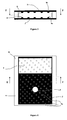
- Figures 5 and 6 show a device according to a second embodiment.
- This mode differs from the previous one only in the structure of the anti-adhesion reliefs which are here not rails but pads 9a and 9b, regularly distributed on all the surfaces of the bottom 2 and the cover 3 traversed by the movable element 6.
- the studs here have the shape of half-spheres and they are evenly distributed over the entire surface of the bottom 2 and the cover 3 in the manner of a carpet of spikes.
- the pads 9a are integral with the bottom 2 and the pads 9b are integral with the cover 3.
Abstract
Description
Le domaine technique de l'invention est celui des dispositifs de sécurité et d'armement de technologie micro électromécanique pour projectile.The technical field of the invention is that of microelectromechanical projectile safety and arming devices.
Les dispositifs de sécurité et d'armement (ou DSA) ont pour but d'isoler le détonateur et le chargement explosif d'un projectile et de ne permettre la communication entre ces deux composantes de la chaîne pyrotechnique qu'exclusivement lorsque (selon les normes actuelles telles que le STANAG n°4157) au moins deux conditions d'environnement de tir distinctes apparaissent.The safety and arming devices (or DSA) are intended to isolate the detonator and the explosive charge of a projectile and to allow communication between these two components of the pyrotechnic chain only when (according to the standards such as STANAG # 4157) at least two distinct shooting environment conditions appear.
On cherche aujourd'hui à réaliser ces dispositifs à l'aide de la technologie MEMS (Micro Electro Mechanical Systems) qui permet une forte miniaturisation propice à l'intégration sur des projectiles de moyen calibre par exemple. L'isolation entre détonateur et chargement est réalisée le plus souvent au moyen d'une plaque aussi appelée écran, tiroir ou barrière, obstruant une lumière faisant communiquer ces deux composantes de la chaîne pyrotechnique. On pourra considérer le brevet
Ces barrières pouvant arrêter un effet pyrotechnique sont de relativement forte épaisseur au regard de la taille d'un dispositif de sécurité d'armement MEMS. Or, l'échelle à laquelle sont construits les MEMS fait que les comportements des mécanismes diffèrent sensiblement des comportements connus pour les mécanismes réalisés à l'échelle centimétrique.These barriers can stop a pyrotechnic effect are relatively thick in view of the size of a MEMS arming security device. However, the scale at which the MEMS are constructed makes that the behavior of the mechanisms differs substantially from the known behaviors for the mechanisms made at the centimetric scale.
Ainsi, les phénomènes d'adhérence pour les pièces épaisses deviennent prépondérants. A l'échelle MEMS, deux surfaces planes mises en contact adhérent l'une à l'autre relativement fortement ce qui gène les mouvements relatifs suivant ces plans. Ce problème est particulièrement présent lorsque l'élément mobile est en contact avec le substrat du MEMS.Thus, the phenomena of adhesion for thick parts become preponderant. At the MEMS scale, two plane surfaces put in contact adhere to each other relatively strongly which causes the relative movements in these planes. This problem is particularly present when the movable element is in contact with the MEMS substrate.
La barrière est alors soumise à des effets d'adhérence indésirables pour un fonctionnement optimal, sûr et fiable du DSA.The barrier is then subjected to undesirable adhesion effects for optimal, safe and reliable operation of the DSA.
L'invention se propose de solutionner les problèmes d'adhérence des pièces mobiles de forte épaisseur du type barrière en équipant les zones du DSA en contact avec la barrière de moyens réduisant l'adhérence et les frottements.The invention proposes to solve the problems of adhesion of thick moving parts of the barrier type by equipping the areas of the DSA in contact with the barrier means reducing adhesion and friction.
La solution proposée consiste à réduire fortement les surfaces de contact entre la barrière ou d'autres éléments mobiles du DSA qui sont en contact avec les surfaces du substrat.The proposed solution is to greatly reduce the contact surfaces between the barrier or other moving elements of the DSA that are in contact with the surfaces of the substrate.
L'invention a ainsi pour objet un dispositif de sécurité et d'armement de technologie micro électromécanique pour un projectile comportant au moins trois couches de substrat: un fond, un couvercle ainsi qu'une couche intermédiaire comportant au moins une partie mobile par rapport aux différentes couches de substrat, dispositif de sécurité et d'armement caractérisé en ce que le fond et le couvercle comportent des reliefs, les reliefs étant régulièrement répartis sur le fond et le couvercle de telle sorte que la partie mobile soit toujours, lors de son déplacement, maintenue en équilibre entre les reliefs du fond et les reliefs du couvercle, les reliefs solidaires du fond étant en contact avec une face inférieure de la partie mobile et les reliefs solidaires du couvercle étant en contact avec une face supérieure de la partie mobile.The subject of the invention is thus a safety and arming device of microelectromechanical technology for a projectile comprising at least three substrate layers: a bottom, a cover and an intermediate layer comprising at least one moving part with respect to different substrate layers, safety and arming device characterized in that the bottom and the cover comprise reliefs, the reliefs being regularly distributed on the bottom and the cover so that the moving part is always, during its displacement , maintained in equilibrium between the reliefs of the bottom and the reliefs of the lid, the reliefs secured to the bottom being in contact with a lower face of the movable part and the integral reliefs of the lid being in contact with an upper face of the movable part.
Selon un premier mode de réalisation de ce dispositif de sécurité et d'armement, les reliefs sont réalisés sous la forme d'au moins deux rails solidaires du fond et d'au moins deux rails solidaires du couvercle, rails parallèles entres eux et orientés logitudinalement suivant la trajectoire que doit suivre l'élément mobile.According to a first embodiment of this safety and arming device, the reliefs are made in the form of at least two rails integral with the bottom and at least two rails secured to the cover, rails parallel thereto and oriented logitudinally. following the path that the moving element must follow.
Selon un second mode de réalisation de ce dispositif de sécurité et d'armement, les reliefs sont réalisés sous la forme de plots, régulièrement répartis sur toutes les surfaces du fond et du couvercle parcourues par l'élément mobile.According to a second embodiment of this safety and arming device, the reliefs are made under the form of studs, evenly distributed over all the surfaces of the bottom and the cover traversed by the movable element.
Selon une variante, les plots pourront avoir la forme de demi sphères.According to one variant, the studs may be in the form of half-spheres.
L'invention sera mieux comprise à la lecture du complément de description suivante en référence aux dessins annexés dans lesquels :
- la
figure 1 représente un dispositif de sécurité et d'armement selon un premier mode de réalisation et suivant une vue en coupe transversale suivant le plan AA, plan de coupe dont la trace est repérée à lafigure 2 , - la
figure 2 représente le dispositif de sécurité et d'armement selon ce premier mode de réalisation, dispositif en position armée, et représenté en coupe longitudinale suivant le plan BB, plan de coupe dont la trace est repérée à lafigure 1 , - la
figure 3 représente le dispositif de sécurité d'armement selon une variante du premier mode de réalisation représenté en coupe transversale suivant le plan CC, plan de coupe dont la trace est repérée à lafigure 4 , - la
figure 4 représente cette même variante du dispositif de sécurité d'armement représenté en coupe longitudinale suivant le plan DD, plan de coupe dont la trace est repérée à lafigure 3 , - la
figure 5 représente le dispositif de sécurité d'armement selon un second mode de réalisation et représenté en coupe transversale suivant le plan EE, plan de coupe dont la trace est repérée à lafigure 6 , et - la
figure 6 représente ce second mode de réalisation, en coupe longitudinale suivant le plan FF, plan dont la trace est repérée à lafigure 5 .
- the
figure 1 represents a safety and arming device according to a first embodiment and in a cross-sectional view along the plane AA, section plane whose trace is marked at thefigure 2 , - the
figure 2 represents the safety and arming device according to this first embodiment, device in the armed position, and shown in longitudinal section along the plane BB, cutting plane whose trace is marked at thefigure 1 , - the
figure 3 represents the arming safety device according to a variant of the first embodiment shown in cross-section along the plane CC, section plane whose trace is marked at thefigure 4 , - the
figure 4 represents the same variant of the arming security device shown in longitudinal section along the plane DD, cutting plane whose trace is located at thefigure 3 , - the
figure 5 represents the arming safety device according to a second embodiment and shown in cross section along the plane EE, section plane whose trace is marked at thefigure 6 , and - the
figure 6 represents this second embodiment, in longitudinal section along the plane FF, plane whose trace is located at thefigure 5 .
La
Ce dispositif est réalisé suivant les technologies MEMS qui sont bien connues de l'Homme du Métier, c'est à dire qui mettent en oeuvre des micro-usinages ou micro-gravures d'un substrat (par exemple le silicium). Concrètement la couche intermédiaire 4 sera réalisée de façon indépendante et la partie mobile 6 sera usinée en même temps que le cadre 4a.This device is made according to the MEMS technologies which are well known to those skilled in the art, that is to say which implement micro-machining or micro-etching of a substrate (for example silicon). Concretely the
Le fond 2 et le couvercle 3 seront usinés par ailleurs et les trois couches 2, 3 et 4 seront ensuite assemblées par collage. Il est clair que les composants MEMS sont réalisés suivant des techniques proches de celles des circuits intégrés. Le dispositif 1 n'est donc pas réalisé seul mais simultanément à de nombreux exemplaires sur un support commun (dénommé généralement Wafer).The
L'assemblage de la couche intermédiaire 4, du fond 2 et du couvercle 3 sera réalisé simultanément pour plusieurs dispositifs par l'assemblage de trois Wafers les uns aux autres. On réalisera ainsi simultanément de nombreux dispositifs.The assembly of the
Bien entendu des moyens de maintien temporaires (non représentés) sont prévus entre la partie mobile 6 et le cadre 4a afin de permettre les positionnements et assemblage des Wafers les uns sur les autres.Of course temporary holding means (not shown) are provided between the
Si on considère donc maintenant un seul dispositif 1, le fond 2 du dispositif ainsi que le couvercle 3 comportent sur leur face interne des reliefs 7a et 7b ayant une fonction anti-adhérence ou anti frottement. Ces reliefs sont en contact avec la face inférieure de la partie mobile 6 pour le fond 2 et avec la face supérieure de la partie mobile 6 pour le couvercle 3.If we now consider only one
La
Pour la clarté de la présentation de l'invention, le dispositif représenté est ici extrêmement simplifié car on n'a fait figurer que la partie mobile 6 et la lumière 5. Il est bien entendu qu'un dispositif de sécurité et d'armement complet comporte d'autres moyens, tels que des moyens moteurs, des verrous et des ressorts...For the clarity of the presentation of the invention, the device shown here is extremely simplified because it has shown only the
L'objet de la présente invention n'est pas le mécanisme complet d'un tel dispositif et on pourra se reporter aux textes des brevets :
Selon ce premier mode de réalisation, les reliefs antiadhérence sont des rails 7a et 7b de section carrée qui sont placés parallèlement entre eux et sur toute la longueur de la cavité 8 de la couche intermédiaire 4, longueur sur laquelle la partie mobile 6 est appelée à se déplacer.According to this first embodiment, the anti-adhesion reliefs are
On notera que la surface totale des rails 7 en contact avec la partie mobile 6 est notablement plus faible que l'aire des faces supérieure et inférieure de la partie mobile 6. On notera aussi que la partie mobile 6 est pincée entre les rails 7b portés par le couvercle 3 et les rails 7a portés par le fond 2. Le mouvement de la partie mobile 6 est donc guidé à la fois par le fond et le couvercle et la surface de contact réduite permet de réduire fortement les frottements.Note that the total surface of the rails 7 in contact with the
On notera que les moyens de l'invention permettent de positionner le dispositif indifféremment sur sa face inférieure, sa face supérieure voire même sur sa tranche. La partie mobile 6 est dans tous les cas maintenue entre les reliefs 7a du fond et 7b du couvercle.It will be noted that the means of the invention make it possible to position the device indifferently on its lower face, its upper face or even on its edge. The
Les
Conformément à l'invention, il est donc préférable que la partie mobile 6 soit, pour toutes les positions qu'elle occupe lors de son déplacement, maintenue en équilibre entre les reliefs 7a solidaires du fond 2 et les reliefs 7b solidaires du couvercle 3.According to the invention, it is therefore preferable that the
Il est aisé d'obtenir un tel équilibre avec des rails s'étendant le long de toute la cavité 8 et régulièrement répartis sur la largeur de cette cavité.It is easy to obtain such a balance with rails extending along the
Avec des reliefs ayant d'autre formes (comme cela sera décrit plus loin en référence aux
Il suffit pour chaque position de la partie mobile 6 de considérer le polygone de sustentation de cette partie mobile qui est formé par les reliefs sur le fond 2 d'une part et le polygone de sustentation formé par les reliefs du couvercle 3 d'autre part.It suffices for each position of the
Si ces deux polygones de sustentation ont toujours une partie commune (en considérant la projection géométrique de ces deux polygones sur le plan de la partie mobile), la partie mobile est effectivement maintenue (ou pincée) entre fond 2 et couvercle 3.If these two levitation polygons always have a common part (considering the geometric projection of these two polygons on the plane of the moving part), the moving part is actually maintained (or pinched) between
Concrètement et de façon simple, l'Homme du Métier répartira les reliefs de façon régulière sur toute les surfaces du fond 2 et du couvercle 3 qui reçoivent la partie mobile 6. Le nombre et l'espacement des reliefs dépendra des dimensions de cette partie mobile 6.Specifically and in a simple manner, the skilled person will distribute the reliefs evenly on all the surfaces of the
A titre d'exemple les
Ce mode ne diffère du précédent que par la structure des reliefs antiadhérence qui sont ici non pas des rails mais des plots 9a et 9b, régulièrement répartis sur toutes les surfaces du fond 2 et du couvercle 3 parcourues par l'élément mobile 6.This mode differs from the previous one only in the structure of the anti-adhesion reliefs which are here not rails but
Les plots ont ici la forme de demi-sphères et ils sont répartis de manière homogène sur toute la surface du fond 2 et du couvercle 3 à la manière d'un tapis de picots. Les plots 9a sont solidaires du fond 2 et les plots 9b sont solidaires du couvercle 3.The studs here have the shape of half-spheres and they are evenly distributed over the entire surface of the
On notera que la surface de contact entre fond 2, partie mobile 6 et couvercle 3 est limitée aux seuls points de tangence entre les demi-sphères et la partie mobile 6.It will be noted that the contact surface between the bottom 2, the moving
Il est bien entendu possible de donner aux plots des formes différentes : pyramidales, coniques ou tronconiques.It is of course possible to give the pads different shapes: pyramidal, conical or frustoconical.
Claims (4)
Priority Applications (1)
| Application Number | Priority Date | Filing Date | Title |
|---|---|---|---|
| PL11290292T PL2402707T3 (en) | 2010-07-02 | 2011-06-30 | Anti-adhesion raised patterns for a safety and arming device |
Applications Claiming Priority (1)
| Application Number | Priority Date | Filing Date | Title |
|---|---|---|---|
| FR1002813A FR2962209B1 (en) | 2010-07-02 | 2010-07-02 | RELIEF ANTI ADHERENCE FOR SAFETY AND ARMING DEVICE |
Publications (2)
| Publication Number | Publication Date |
|---|---|
| EP2402707A1 true EP2402707A1 (en) | 2012-01-04 |
| EP2402707B1 EP2402707B1 (en) | 2013-08-07 |
Family
ID=43589956
Family Applications (1)
| Application Number | Title | Priority Date | Filing Date |
|---|---|---|---|
| EP11290292.9A Active EP2402707B1 (en) | 2010-07-02 | 2011-06-30 | Anti-adhesion raised patterns for a safety and arming device |
Country Status (5)
| Country | Link |
|---|---|
| US (1) | US9194682B2 (en) |
| EP (1) | EP2402707B1 (en) |
| ES (1) | ES2431937T3 (en) |
| FR (1) | FR2962209B1 (en) |
| PL (1) | PL2402707T3 (en) |
Cited By (1)
| Publication number | Priority date | Publication date | Assignee | Title |
|---|---|---|---|---|
| CN114061386A (en) * | 2021-11-17 | 2022-02-18 | 南京理工大学 | MOEMS fuse safety device with state monitoring function |
Citations (5)
| Publication number | Priority date | Publication date | Assignee | Title |
|---|---|---|---|---|
| EP1780496A1 (en) | 2005-10-27 | 2007-05-02 | NEXTER Munitions | Pyrotechnical safety device with micromachined barrier. |
| EP1780495A1 (en) | 2005-10-27 | 2007-05-02 | NEXTER Munitions | Small-sized pyrothechnic safety device. |
| EP2077431A2 (en) | 2008-01-07 | 2009-07-08 | Nexter Munitions | Micro-machined or micro-engraved weaponry and security device |
| FR2932561A1 (en) | 2008-06-11 | 2009-12-18 | Nexter Munitions | MICRO INITIATOR SECURE |
| FR2934042A1 (en) * | 2008-07-16 | 2010-01-22 | Memscap | Secure firing device for pyrotechnic device of micro-electro-mechanical system, has channel connecting initiator and explosive section, and set of actuators assuring progressive displacement of element under effect of control signal |
Family Cites Families (8)
| Publication number | Priority date | Publication date | Assignee | Title |
|---|---|---|---|---|
| US5705767A (en) * | 1997-01-30 | 1998-01-06 | The United States Of America As Represented By The Secretary Of The Army | Miniature, planar, inertially-damped, inertially-actuated delay slider actuator |
| US6321654B1 (en) * | 2000-02-22 | 2001-11-27 | The United States Of America As Represented By The Secretary Of The Army | Microelectromechanical systems (MEMS) -type devices having latch release and output mechanisms |
| US6765160B1 (en) * | 2002-08-21 | 2004-07-20 | The United States Of America As Represented By The Secetary Of The Army | Omnidirectional microscale impact switch |
| US7051656B1 (en) * | 2003-08-14 | 2006-05-30 | Sandia Corporation | Microelectromechanical safing and arming apparatus |
| US7493858B1 (en) * | 2005-01-06 | 2009-02-24 | The United States Of America As Represented By The Secretary Of The Navy | MEMS inertial delay device |
| JP4718546B2 (en) * | 2005-05-30 | 2011-07-06 | 三星ダイヤモンド工業株式会社 | Brittle material substrate cutting apparatus and method |
| US7530312B1 (en) * | 2006-06-14 | 2009-05-12 | Sandia Corporation | Inertial sensing microelectromechanical (MEM) safe-arm device |
| FR2954505B1 (en) * | 2009-12-22 | 2012-08-03 | Commissariat Energie Atomique | MICROMECHANICAL STRUCTURE COMPRISING A MOBILE PART HAVING STOPS FOR OFFLINE SHIFTS OF THE STRUCTURE AND METHOD FOR CARRYING OUT THE SAME |
-
2010
- 2010-07-02 FR FR1002813A patent/FR2962209B1/en not_active Expired - Fee Related
-
2011
- 2011-06-30 EP EP11290292.9A patent/EP2402707B1/en active Active
- 2011-06-30 PL PL11290292T patent/PL2402707T3/en unknown
- 2011-06-30 ES ES11290292T patent/ES2431937T3/en active Active
- 2011-07-05 US US13/176,415 patent/US9194682B2/en active Active
Patent Citations (5)
| Publication number | Priority date | Publication date | Assignee | Title |
|---|---|---|---|---|
| EP1780496A1 (en) | 2005-10-27 | 2007-05-02 | NEXTER Munitions | Pyrotechnical safety device with micromachined barrier. |
| EP1780495A1 (en) | 2005-10-27 | 2007-05-02 | NEXTER Munitions | Small-sized pyrothechnic safety device. |
| EP2077431A2 (en) | 2008-01-07 | 2009-07-08 | Nexter Munitions | Micro-machined or micro-engraved weaponry and security device |
| FR2932561A1 (en) | 2008-06-11 | 2009-12-18 | Nexter Munitions | MICRO INITIATOR SECURE |
| FR2934042A1 (en) * | 2008-07-16 | 2010-01-22 | Memscap | Secure firing device for pyrotechnic device of micro-electro-mechanical system, has channel connecting initiator and explosive section, and set of actuators assuring progressive displacement of element under effect of control signal |
Cited By (1)
| Publication number | Priority date | Publication date | Assignee | Title |
|---|---|---|---|---|
| CN114061386A (en) * | 2021-11-17 | 2022-02-18 | 南京理工大学 | MOEMS fuse safety device with state monitoring function |
Also Published As
| Publication number | Publication date |
|---|---|
| US20120000388A1 (en) | 2012-01-05 |
| FR2962209A1 (en) | 2012-01-06 |
| EP2402707B1 (en) | 2013-08-07 |
| ES2431937T3 (en) | 2013-11-28 |
| FR2962209B1 (en) | 2012-07-13 |
| PL2402707T3 (en) | 2013-12-31 |
| US9194682B2 (en) | 2015-11-24 |
Similar Documents
| Publication | Publication Date | Title |
|---|---|---|
| EP1780495B1 (en) | Small-sized pyrothechnic safety device. | |
| EP2776736B1 (en) | Filtration device of the pendular oscillator type comprising an improved guidance system | |
| EP2402706B1 (en) | Safety and arming device with MEMS technology inertia lock | |
| EP2077431B1 (en) | Micro-machined or micro-engraved safing and arming device | |
| WO2016059331A1 (en) | Deployable grille with fins for aircraft turbine engine thrust-reversal system | |
| EP2402707B1 (en) | Anti-adhesion raised patterns for a safety and arming device | |
| FR2944348A1 (en) | PERCUSSION MUNITING DEVICE | |
| WO2013068496A1 (en) | Anchoring harpoon and associated anchoring method | |
| EP2482027B1 (en) | Arming and security device for a pyrotechnic chain of a projectile | |
| EP0064465A1 (en) | Shock and/or vibration damping device between a supporting and a supported member | |
| EP0034532A2 (en) | Gravity-deployed bidirectional mine with a hollow charge | |
| EP0566469A1 (en) | Safety and arming device for the fuse of a projectile comprising an anti-vibratory means | |
| EP2482029B1 (en) | Device for timing a movement of a micro-machined balance weight and security and weaponry device including such a timer device | |
| EP3344485A1 (en) | Device for sealing a front-end air intake of a motor vehicle and front-end module for a motor vehicle | |
| FR2934042A1 (en) | Secure firing device for pyrotechnic device of micro-electro-mechanical system, has channel connecting initiator and explosive section, and set of actuators assuring progressive displacement of element under effect of control signal | |
| FR3016156A1 (en) | STRUCTURE FOR REGULATING THE AEROACOUSTIC ENVIRONMENT IN AN AIRCRAFT ARMOR | |
| EP2788631B1 (en) | Breakable attachment device, and assembly of at least two plates comprising such a breakable attachment device | |
| FR3047306A1 (en) | CYLINDRICAL ENVELOPE FOR USEFUL LOAD | |
| EP3097266A1 (en) | Mobile member of a turbomachine which comprises means for changing the resonance frequency of same | |
| FR2883143A1 (en) | CIRCULAR TABLE WITH PERIMETER OF MODIFIABLE TRAY | |
| EP1209344A1 (en) | Rocket nozzle | |
| FR2971317A1 (en) | Mechanical module for exerting axial effort in rotating elements integrated in e.g. gear box of motor vehicle, has internal plate whose angular movement allows axial movement of plate relative to other plate | |
| FR2855118A1 (en) | SLIDING CONSOLE SYSTEM | |
| EP1292178A1 (en) | Suspension for electronic module operated during, and after serious impact | |
| FR2853024A1 (en) | DEVICE FOR FIXING EQUIPMENT AND / OR USEFUL LOAD LIKELY TO BE SUBJECT TO A VIBRATORY ATMOSPHERE |
Legal Events
| Date | Code | Title | Description |
|---|---|---|---|
| AK | Designated contracting states |
Kind code of ref document: A1 Designated state(s): AL AT BE BG CH CY CZ DE DK EE ES FI FR GB GR HR HU IE IS IT LI LT LU LV MC MK MT NL NO PL PT RO RS SE SI SK SM TR |
|
| AX | Request for extension of the european patent |
Extension state: BA ME |
|
| PUAI | Public reference made under article 153(3) epc to a published international application that has entered the european phase |
Free format text: ORIGINAL CODE: 0009012 |
|
| 17P | Request for examination filed |
Effective date: 20120619 |
|
| GRAP | Despatch of communication of intention to grant a patent |
Free format text: ORIGINAL CODE: EPIDOSNIGR1 |
|
| RIC1 | Information provided on ipc code assigned before grant |
Ipc: F42C 15/34 20060101AFI20130131BHEP |
|
| GRAS | Grant fee paid |
Free format text: ORIGINAL CODE: EPIDOSNIGR3 |
|
| GRAA | (expected) grant |
Free format text: ORIGINAL CODE: 0009210 |
|
| AK | Designated contracting states |
Kind code of ref document: B1 Designated state(s): AL AT BE BG CH CY CZ DE DK EE ES FI FR GB GR HR HU IE IS IT LI LT LU LV MC MK MT NL NO PL PT RO RS SE SI SK SM TR |
|
| REG | Reference to a national code |
Ref country code: GB Ref legal event code: FG4D Free format text: NOT ENGLISH |
|
| REG | Reference to a national code |
Ref country code: AT Ref legal event code: REF Ref document number: 625941 Country of ref document: AT Kind code of ref document: T Effective date: 20130815 Ref country code: CH Ref legal event code: EP |
|
| REG | Reference to a national code |
Ref country code: IE Ref legal event code: FG4D Free format text: LANGUAGE OF EP DOCUMENT: FRENCH |
|
| REG | Reference to a national code |
Ref country code: DE Ref legal event code: R096 Ref document number: 602011002611 Country of ref document: DE Effective date: 20131002 |
|
| REG | Reference to a national code |
Ref country code: SE Ref legal event code: TRGR |
|
| REG | Reference to a national code |
Ref country code: AT Ref legal event code: MK05 Ref document number: 625941 Country of ref document: AT Kind code of ref document: T Effective date: 20130807 |
|
| REG | Reference to a national code |
Ref country code: NO Ref legal event code: T2 Effective date: 20130807 |
|
| REG | Reference to a national code |
Ref country code: PL Ref legal event code: T3 |
|
| REG | Reference to a national code |
Ref country code: LT Ref legal event code: MG4D |
|
| REG | Reference to a national code |
Ref country code: NL Ref legal event code: T3 |
|
| PG25 | Lapsed in a contracting state [announced via postgrant information from national office to epo] |
Ref country code: CY Free format text: LAPSE BECAUSE OF FAILURE TO SUBMIT A TRANSLATION OF THE DESCRIPTION OR TO PAY THE FEE WITHIN THE PRESCRIBED TIME-LIMIT Effective date: 20130731 Ref country code: HR Free format text: LAPSE BECAUSE OF FAILURE TO SUBMIT A TRANSLATION OF THE DESCRIPTION OR TO PAY THE FEE WITHIN THE PRESCRIBED TIME-LIMIT Effective date: 20130807 Ref country code: IS Free format text: LAPSE BECAUSE OF FAILURE TO SUBMIT A TRANSLATION OF THE DESCRIPTION OR TO PAY THE FEE WITHIN THE PRESCRIBED TIME-LIMIT Effective date: 20131207 Ref country code: AT Free format text: LAPSE BECAUSE OF FAILURE TO SUBMIT A TRANSLATION OF THE DESCRIPTION OR TO PAY THE FEE WITHIN THE PRESCRIBED TIME-LIMIT Effective date: 20130807 Ref country code: LT Free format text: LAPSE BECAUSE OF FAILURE TO SUBMIT A TRANSLATION OF THE DESCRIPTION OR TO PAY THE FEE WITHIN THE PRESCRIBED TIME-LIMIT Effective date: 20130807 Ref country code: PT Free format text: LAPSE BECAUSE OF FAILURE TO SUBMIT A TRANSLATION OF THE DESCRIPTION OR TO PAY THE FEE WITHIN THE PRESCRIBED TIME-LIMIT Effective date: 20131209 |
|
| REG | Reference to a national code |
Ref country code: NL Ref legal event code: T3 |
|
| PG25 | Lapsed in a contracting state [announced via postgrant information from national office to epo] |
Ref country code: GR Free format text: LAPSE BECAUSE OF FAILURE TO SUBMIT A TRANSLATION OF THE DESCRIPTION OR TO PAY THE FEE WITHIN THE PRESCRIBED TIME-LIMIT Effective date: 20131108 Ref country code: LV Free format text: LAPSE BECAUSE OF FAILURE TO SUBMIT A TRANSLATION OF THE DESCRIPTION OR TO PAY THE FEE WITHIN THE PRESCRIBED TIME-LIMIT Effective date: 20130807 Ref country code: SI Free format text: LAPSE BECAUSE OF FAILURE TO SUBMIT A TRANSLATION OF THE DESCRIPTION OR TO PAY THE FEE WITHIN THE PRESCRIBED TIME-LIMIT Effective date: 20130807 Ref country code: FI Free format text: LAPSE BECAUSE OF FAILURE TO SUBMIT A TRANSLATION OF THE DESCRIPTION OR TO PAY THE FEE WITHIN THE PRESCRIBED TIME-LIMIT Effective date: 20130807 |
|
| PG25 | Lapsed in a contracting state [announced via postgrant information from national office to epo] |
Ref country code: CY Free format text: LAPSE BECAUSE OF FAILURE TO SUBMIT A TRANSLATION OF THE DESCRIPTION OR TO PAY THE FEE WITHIN THE PRESCRIBED TIME-LIMIT Effective date: 20130807 |
|
| PG25 | Lapsed in a contracting state [announced via postgrant information from national office to epo] |
Ref country code: CZ Free format text: LAPSE BECAUSE OF FAILURE TO SUBMIT A TRANSLATION OF THE DESCRIPTION OR TO PAY THE FEE WITHIN THE PRESCRIBED TIME-LIMIT Effective date: 20130807 Ref country code: EE Free format text: LAPSE BECAUSE OF FAILURE TO SUBMIT A TRANSLATION OF THE DESCRIPTION OR TO PAY THE FEE WITHIN THE PRESCRIBED TIME-LIMIT Effective date: 20130807 Ref country code: SK Free format text: LAPSE BECAUSE OF FAILURE TO SUBMIT A TRANSLATION OF THE DESCRIPTION OR TO PAY THE FEE WITHIN THE PRESCRIBED TIME-LIMIT Effective date: 20130807 Ref country code: RO Free format text: LAPSE BECAUSE OF FAILURE TO SUBMIT A TRANSLATION OF THE DESCRIPTION OR TO PAY THE FEE WITHIN THE PRESCRIBED TIME-LIMIT Effective date: 20130807 Ref country code: DK Free format text: LAPSE BECAUSE OF FAILURE TO SUBMIT A TRANSLATION OF THE DESCRIPTION OR TO PAY THE FEE WITHIN THE PRESCRIBED TIME-LIMIT Effective date: 20130807 |
|
| PLBE | No opposition filed within time limit |
Free format text: ORIGINAL CODE: 0009261 |
|
| STAA | Information on the status of an ep patent application or granted ep patent |
Free format text: STATUS: NO OPPOSITION FILED WITHIN TIME LIMIT |
|
| 26N | No opposition filed |
Effective date: 20140508 |
|
| REG | Reference to a national code |
Ref country code: DE Ref legal event code: R097 Ref document number: 602011002611 Country of ref document: DE Effective date: 20140508 |
|
| PG25 | Lapsed in a contracting state [announced via postgrant information from national office to epo] |
Ref country code: LU Free format text: LAPSE BECAUSE OF FAILURE TO SUBMIT A TRANSLATION OF THE DESCRIPTION OR TO PAY THE FEE WITHIN THE PRESCRIBED TIME-LIMIT Effective date: 20140630 Ref country code: MC Free format text: LAPSE BECAUSE OF FAILURE TO SUBMIT A TRANSLATION OF THE DESCRIPTION OR TO PAY THE FEE WITHIN THE PRESCRIBED TIME-LIMIT Effective date: 20130807 |
|
| REG | Reference to a national code |
Ref country code: IE Ref legal event code: MM4A |
|
| PG25 | Lapsed in a contracting state [announced via postgrant information from national office to epo] |
Ref country code: IE Free format text: LAPSE BECAUSE OF NON-PAYMENT OF DUE FEES Effective date: 20140630 |
|
| PG25 | Lapsed in a contracting state [announced via postgrant information from national office to epo] |
Ref country code: MT Free format text: LAPSE BECAUSE OF FAILURE TO SUBMIT A TRANSLATION OF THE DESCRIPTION OR TO PAY THE FEE WITHIN THE PRESCRIBED TIME-LIMIT Effective date: 20130807 |
|
| REG | Reference to a national code |
Ref country code: FR Ref legal event code: PLFP Year of fee payment: 6 |
|
| PG25 | Lapsed in a contracting state [announced via postgrant information from national office to epo] |
Ref country code: SM Free format text: LAPSE BECAUSE OF FAILURE TO SUBMIT A TRANSLATION OF THE DESCRIPTION OR TO PAY THE FEE WITHIN THE PRESCRIBED TIME-LIMIT Effective date: 20130807 |
|
| PG25 | Lapsed in a contracting state [announced via postgrant information from national office to epo] |
Ref country code: BG Free format text: LAPSE BECAUSE OF FAILURE TO SUBMIT A TRANSLATION OF THE DESCRIPTION OR TO PAY THE FEE WITHIN THE PRESCRIBED TIME-LIMIT Effective date: 20130807 Ref country code: RS Free format text: LAPSE BECAUSE OF FAILURE TO SUBMIT A TRANSLATION OF THE DESCRIPTION OR TO PAY THE FEE WITHIN THE PRESCRIBED TIME-LIMIT Effective date: 20130807 |
|
| PG25 | Lapsed in a contracting state [announced via postgrant information from national office to epo] |
Ref country code: HU Free format text: LAPSE BECAUSE OF FAILURE TO SUBMIT A TRANSLATION OF THE DESCRIPTION OR TO PAY THE FEE WITHIN THE PRESCRIBED TIME-LIMIT; INVALID AB INITIO Effective date: 20110630 |
|
| REG | Reference to a national code |
Ref country code: FR Ref legal event code: PLFP Year of fee payment: 7 |
|
| REG | Reference to a national code |
Ref country code: FR Ref legal event code: PLFP Year of fee payment: 8 |
|
| PG25 | Lapsed in a contracting state [announced via postgrant information from national office to epo] |
Ref country code: MK Free format text: LAPSE BECAUSE OF FAILURE TO SUBMIT A TRANSLATION OF THE DESCRIPTION OR TO PAY THE FEE WITHIN THE PRESCRIBED TIME-LIMIT Effective date: 20130807 |
|
| PG25 | Lapsed in a contracting state [announced via postgrant information from national office to epo] |
Ref country code: AL Free format text: LAPSE BECAUSE OF FAILURE TO SUBMIT A TRANSLATION OF THE DESCRIPTION OR TO PAY THE FEE WITHIN THE PRESCRIBED TIME-LIMIT Effective date: 20130807 |
|
| PGFP | Annual fee paid to national office [announced via postgrant information from national office to epo] |
Ref country code: NO Payment date: 20230525 Year of fee payment: 13 Ref country code: NL Payment date: 20230523 Year of fee payment: 13 Ref country code: IT Payment date: 20230523 Year of fee payment: 13 Ref country code: FR Payment date: 20230523 Year of fee payment: 13 Ref country code: DE Payment date: 20230523 Year of fee payment: 13 |
|
| PGFP | Annual fee paid to national office [announced via postgrant information from national office to epo] |
Ref country code: TR Payment date: 20230529 Year of fee payment: 13 Ref country code: SE Payment date: 20230523 Year of fee payment: 13 Ref country code: PL Payment date: 20230525 Year of fee payment: 13 |
|
| PGFP | Annual fee paid to national office [announced via postgrant information from national office to epo] |
Ref country code: BE Payment date: 20230523 Year of fee payment: 13 |
|
| PGFP | Annual fee paid to national office [announced via postgrant information from national office to epo] |
Ref country code: GB Payment date: 20230523 Year of fee payment: 13 Ref country code: ES Payment date: 20230703 Year of fee payment: 13 Ref country code: CH Payment date: 20230702 Year of fee payment: 13 |