EP2402693A2 - Nasskühlturm mit saugendem Lüfter - Google Patents
Nasskühlturm mit saugendem Lüfter Download PDFInfo
- Publication number
- EP2402693A2 EP2402693A2 EP11250584A EP11250584A EP2402693A2 EP 2402693 A2 EP2402693 A2 EP 2402693A2 EP 11250584 A EP11250584 A EP 11250584A EP 11250584 A EP11250584 A EP 11250584A EP 2402693 A2 EP2402693 A2 EP 2402693A2
- Authority
- EP
- European Patent Office
- Prior art keywords
- heat exchange
- section
- cooling tower
- exchange section
- air inlet
- Prior art date
- Legal status (The legal status is an assumption and is not a legal conclusion. Google has not performed a legal analysis and makes no representation as to the accuracy of the status listed.)
- Withdrawn
Links
- 238000001816 cooling Methods 0.000 title claims abstract description 115
- 239000007788 liquid Substances 0.000 claims abstract description 34
- XLYOFNOQVPJJNP-UHFFFAOYSA-N water Substances O XLYOFNOQVPJJNP-UHFFFAOYSA-N 0.000 claims description 40
- 230000007423 decrease Effects 0.000 claims description 7
- 239000012530 fluid Substances 0.000 description 9
- 238000000034 method Methods 0.000 description 9
- 229910001335 Galvanized steel Inorganic materials 0.000 description 3
- 239000008397 galvanized steel Substances 0.000 description 3
- 239000007921 spray Substances 0.000 description 3
- 239000010935 stainless steel Substances 0.000 description 3
- 229910001220 stainless steel Inorganic materials 0.000 description 3
- 229920003023 plastic Polymers 0.000 description 1
- 239000004033 plastic Substances 0.000 description 1
- 229920000915 polyvinyl chloride Polymers 0.000 description 1
- 239000004800 polyvinyl chloride Substances 0.000 description 1
Images

Classifications
-
- F—MECHANICAL ENGINEERING; LIGHTING; HEATING; WEAPONS; BLASTING
- F28—HEAT EXCHANGE IN GENERAL
- F28C—HEAT-EXCHANGE APPARATUS, NOT PROVIDED FOR IN ANOTHER SUBCLASS, IN WHICH THE HEAT-EXCHANGE MEDIA COME INTO DIRECT CONTACT WITHOUT CHEMICAL INTERACTION
- F28C1/00—Direct-contact trickle coolers, e.g. cooling towers
- F28C1/02—Direct-contact trickle coolers, e.g. cooling towers with counter-current only
-
- F—MECHANICAL ENGINEERING; LIGHTING; HEATING; WEAPONS; BLASTING
- F28—HEAT EXCHANGE IN GENERAL
- F28C—HEAT-EXCHANGE APPARATUS, NOT PROVIDED FOR IN ANOTHER SUBCLASS, IN WHICH THE HEAT-EXCHANGE MEDIA COME INTO DIRECT CONTACT WITHOUT CHEMICAL INTERACTION
- F28C1/00—Direct-contact trickle coolers, e.g. cooling towers
- F28C1/14—Direct-contact trickle coolers, e.g. cooling towers comprising also a non-direct contact heat exchange
-
- F—MECHANICAL ENGINEERING; LIGHTING; HEATING; WEAPONS; BLASTING
- F28—HEAT EXCHANGE IN GENERAL
- F28D—HEAT-EXCHANGE APPARATUS, NOT PROVIDED FOR IN ANOTHER SUBCLASS, IN WHICH THE HEAT-EXCHANGE MEDIA DO NOT COME INTO DIRECT CONTACT
- F28D5/00—Heat-exchange apparatus having stationary conduit assemblies for one heat-exchange medium only, the media being in contact with different sides of the conduit wall, using the cooling effect of natural or forced evaporation
- F28D5/02—Heat-exchange apparatus having stationary conduit assemblies for one heat-exchange medium only, the media being in contact with different sides of the conduit wall, using the cooling effect of natural or forced evaporation in which the evaporating medium flows in a continuous film or trickles freely over the conduits
-
- F—MECHANICAL ENGINEERING; LIGHTING; HEATING; WEAPONS; BLASTING
- F28—HEAT EXCHANGE IN GENERAL
- F28F—DETAILS OF HEAT-EXCHANGE AND HEAT-TRANSFER APPARATUS, OF GENERAL APPLICATION
- F28F25/00—Component parts of trickle coolers
-
- F—MECHANICAL ENGINEERING; LIGHTING; HEATING; WEAPONS; BLASTING
- F28—HEAT EXCHANGE IN GENERAL
- F28F—DETAILS OF HEAT-EXCHANGE AND HEAT-TRANSFER APPARATUS, OF GENERAL APPLICATION
- F28F25/00—Component parts of trickle coolers
- F28F25/10—Component parts of trickle coolers for feeding gas or vapour
- F28F25/12—Ducts; Guide vanes, e.g. for carrying currents to distinct zones
-
- Y—GENERAL TAGGING OF NEW TECHNOLOGICAL DEVELOPMENTS; GENERAL TAGGING OF CROSS-SECTIONAL TECHNOLOGIES SPANNING OVER SEVERAL SECTIONS OF THE IPC; TECHNICAL SUBJECTS COVERED BY FORMER USPC CROSS-REFERENCE ART COLLECTIONS [XRACs] AND DIGESTS
- Y02—TECHNOLOGIES OR APPLICATIONS FOR MITIGATION OR ADAPTATION AGAINST CLIMATE CHANGE
- Y02B—CLIMATE CHANGE MITIGATION TECHNOLOGIES RELATED TO BUILDINGS, e.g. HOUSING, HOUSE APPLIANCES OR RELATED END-USER APPLICATIONS
- Y02B30/00—Energy efficient heating, ventilation or air conditioning [HVAC]
- Y02B30/70—Efficient control or regulation technologies, e.g. for control of refrigerant flow, motor or heating
Definitions
- the present invention relates generally to a heat exchange apparatus such as cooling tower or evaporative condenser. More specifically, the present invention relates to a water saving cooling tower including a dry sensible heat exchange section and an evaporative heat exchange section.
- cooling towers comprising dry sensible and evaporative heat exchange sections
- cooling towers having a dry sensible heat exchange section above the evaporative heat exchange section typically the exhaust air is drawn across and upwardly by a fan.
- the dry sensible heat exchange section usually provides a relatively fixed sensible cooling capacity percentage relative to the total cooling capacity of the cooling tower. It is desirable to allow the sensible heat exchange section to take on a greater percentage of the total cooling load, especially as the ambient temperatures drop or the total cooling load on the cooling tower decreases.
- an initially hot fluid usually water
- the hot water undergoes indirect sensible heat exchange with a counter flowing air stream drawn through the cooling tower by a fan mechanism.
- Such operation is typically referred to as dry coil operation whereby the sensible cooling to the water or other liquids passing within the dry sensible heat exchange section coils are cooled by the air alone.
- An evaporative heat exchange section is located below the dry sensible heat exchange section.
- the evaporative heat exchange section typically is comprised of a series of closed circuits arranged in a spaced and adjacent configuration such that fluid to be cooled, usually water, travels downwardly within the circuits.
- An evaporative liquid, usually water, is sprayed downwardly across the circuits in a manner such that the water is spread evenly across the entire outside surfaces of each circuit and picks up heat from the fluid inside the circuits.
- Air that provides cooling to the evaporative liquid falling downwardly over the circuits is drawn counter to the flowing evaporative liquid by fan mechanism.
- energy is transferred from the evaporative liquid to the air stream by a combination of heat and mass transfer processes.
- the evaporative liquid is then collected in a sump, which is then redistributed to the top of the evaporative heat exchange section. This is typically called a closed circuit cooling tower.
- operation may by as an evaporative condenser.
- a gas to be condensed is passed through the dry sensible heat exchange section coils whereby the cooling air drawn across the such dry sensible heat exchange section by the fan results in the desuperheating and partial condensing of the gas.
- the remainder of the gas is condensed in the evaporative heat exchanger.
- operation may be as an open cooling tower. In typical operation of a dry sensible heat exchange section as part of an open cooling tower, an initially hot fluid, usually water, is directed downwardly through a series of circuits which comprise the dry sensible heat exchange section.
- the fluid is then sprayed directly over a direct contact evaporative heat exchanger media, typically comprised of spaced fill sheets, where it is further cooled in a combined heat and mass transfer process with the counter flowing air.
- the cooled fluid is then collected in a sump, and then pumped out to a process where it picks up heat to be circulated back to the tower.
- the sides of the tower below the dry sensible heat exchanger and above the evaporative heat exchanger are replaced with modulating louvers.
- the modulating louvers or dampers can be opened to increase the air flow across the dry sensible heat exchange section, typically as the ambient temperatures drop or the total cooling load on the tower decreases. This increases both the total air flow through the tower and the relative percentage of air across the dry sensible heat exchange section coil which increase the dry sensible coils' cooling capacity. Simultaneously it also reduces the relative air flow across the evaporative heat exchange section and reduces the capacity of the evaporative heat exchange section. Accordingly, a greater portion of the total cooling load is provided by the dry sensible heat exchange coil which operates as a dry coil, and saves an amount of water evaporated to provide cooling in the total cooling tower itself.
- a cooling tower is shown generally at 10.
- Such cooling tower is an induced draft tower as fan 12 and fan plenum 13 are generally located at the top of the cooling tower thereby drawing air through inlets 18, 22 located at the sides of the cooling tower.
- the cooling tower itself is seen to be a generally rectangular structure, usually comprised of galvanized steel or stainless steel structural components.
- Upper section 14 of cooling tower 10 is seen to comprise a dry sensible cooling coil section 16.
- Modulating louvers 18 are located in the sides of cooling tower 10, thereby allowing the air flow through modulating louvers 18 to be adjusted from basically full air passage to, upon closing of such louvers, no air passage.
- Lower section 20 of cooling tower 10 is seen to comprise an evaporative cooling section 21.
- evaporative section typically is comprised of a series of spaced parallel closed circuits or fill sheets, designed to have an evaporative liquid fall across such circuits or fill sheets.
- fill sheets usually are comprised of a poly vinyl chloride or similar plastic and are usually of a rectangular shape. Overall, the sheets are of a flat configuration, but various wave and groove patterns are utilized.
- Sump 28 is seen to collect the evaporative liquid, typically water. In a closed circuit cooling tower or an evaporative condenser this evaporative liquid in the sump is pumped upwardly through water supply line 30 to water distribution line 24.
- the evaporative liquid in the sump is pumped to a heat exchanger where it picks up heat to be rejected from a process.
- the heated water then returns to the dry sensible heat transfer section where it is partially cooled.
- the process fluid then flows to the water distribution line 24.
- the process fluid and the evaporative fluid are one in the same.
- a plurality of spray nozzles 26 extend from water distribution line 24 in a spaced arrangement such that the evaporative liquid, typically water, is sprayed across the entire top surface of the evaporative coil or fill section 21. It should be understood that separate nozzles may not be utilized, but in an alternate embodiment, openings in water distribution line 24 may be designed and configured that result in water being sprayed from water distribution line 24.
- Air inlet louvers 22 are provided generally below evaporative cooling section 21. These louvers are typically open to air flow, but can also be modulated to allow the air flow to be adjusted from full air flow to, upon closing of such louvers, zero flow. Drift eliminators 32 prevent the evaporative liquid sprayed from nozzles 26 from being drawn into the upper section 14 of the cooling tower.
- a cooling tower is shown generally at 110.
- Such cooling tower is an induced draft tower as fan 112 and plenum 113 are generally located at the top of the cooling tower thereby drawing air through inlets 118, 122 located at the sides of the cooling tower.
- the cooling tower itself is seen to be a generally rectangular structure, usually comprised of galvanized steel or stainless steel structural components.
- Upper section 114 of cooling tower 110 is seen to comprise a dry sensible cooling coil section 116 having coil 117.
- This coil 117 receives a liquid, usually water, from a process that imparts heat to the liquid.
- the liquid in the coil is indirectly cooled by the air being drawn across upper portion of coil 117 by fan 112.
- Modulating louvers 118 are located in the sides of cooling tower 110, thereby allowing the airflow in through modulating louvers 118 to be adjusted from basically full air passage to, upon closing modulating louvers 118, no air passage. Accordingly, the cooling load of coil 117 can be adjusted from a large portion of the total cooling load of cooling tower 110, with modulating louvers 118 fully open, to a small portion of the total cooling load of cooling tower 110, with modulating louvers 118 closed.
- Lower section 120 of cooling tower 110 is seen to comprise an evaporative cooling section 121.
- Evaporative cooling section 121 is comprised of a cooling coil section 123 which includes a series of closed circuits for further indirect cooling of the liquid passing into cooling coil section 123 from cooling coil 117.
- An evaporative liquid, usually water, falls across cooling coil section 123. Sump 28 collects the evaporative liquid.
- the evaporative liquid is pumped upwardly through water supply line 130 to water distribution line 124.
- a plurality of spray nozzles 126 extend from openings in water distribution line 124 in a spaced arrangement such that the evaporative liquid is sprayed across the entire top surface of cooling coil 123. It should be understood that separate nozzles may not be utilized, but in an alternate embodiment, openings in water distribution line 124 may be designed and configured that result in water being sprayed or otherwise distributed from water distribution line 124. Other functional equivalents to nozzles or openings may also be utilized. Cooled or condensed liquid exits cooling coil 123 at 125. An air inlet louver 122 is provided generally below evaporative cooling section 121.
- Louvers 122 are typically open to air flow, but can also be modulated to allow the air flow to be adjusted from full air flow to, upon closing of louvers 122, zero air flow.
- Drift eliminators 132 prevent the evaporative liquid sprayed from nozzles 126 from being drawn into the upper section 114 of the cooling tower.
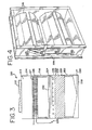
- a cooling tower is shown generally at 210.
- Such cooling tower is an induced draft tower as fan 212 and fan plenum 213 are generally located at the top of the cooling tower thereby drawing air through inlets located at the sides of the cooling tower.
- the cooling tower itself is seen to be a generally rectangular structure, usually comprised of galvanized steel or stainless steel structural components.
- Upper section 214 of cooling tower 210 is seen to comprise a dry sensible cooling coil section 216 having the coil 217.
- This coil 217 receives a liquid, usually water, from a process that imparts heat to the liquid.
- the liquid in coil 217 is indirectly cooled by the air being drawn across coil 217 by fan 212.
- Modulating louvers 218 are located in the sides of cooling tower 210, thereby allowing the air flow through modulating louvers 218 to be adjusted from basically full air passage to, upon closing modulating louvers 218, no air passage.
- the cooling load of coil 217 can be adjusted from a large portion of the total cooling load of cooling tower 210, with modulating louvers 218 fully open, to a small portion of the total cooling load of cooling tower 210, with modulating louvers 218 closed.
- Lower section 220 of cooling tower 210 is seen to comprise an evaporative cooling section 221.
- Evaporative cooling section 221 is comprised of a fill section 223 which includes a series of spaced fill sheets for direct cooling of the liquid from coil 217, which passes through connection 238 to fall across fill section 223.
- a plurality of spray nozzles 226 extend from water distribution line 224 in a spaced arrangement such that the evaporative liquid from connection 238 is sprayed across the entire top surface of fill section 223. It should be understood that separate nozzles may not be utilized, but in an alternate embodiment, openings in water distribution line 224 may be designed and configured that result in water being sprayed or otherwise distributed from water distribution line 224. Other functional equivalents to nozzles or openings may also be utilized.
- Sump 228 collects the evaporative liquid falling from fill section 223.
- the evaporative liquid is pumped outwardly through water supply line 230 to be again used in a cooling operation such as a water cooled condenser.
- Drift eliminators 232 prevent the evaporative liquid sprayed from nozzles 226 from being drawn into the upper section 214 of the cooling tower.
- Air inlet louvers 222 are provided generally below evaporative cooling section 221. Louvers 222 are typically open to air flow, but can also be modulated to allow the air flow to be adjusted from full air flow to, upon closing the louvers 222, zero air flow.
- modulating louvers 318 are shown in detail. Mechanical controls 338 are seen to readily be able to open and close modulating louvers 318 to either allow complete airflow therethrough or to basically stop airflow from entering the upper section.
Landscapes
- Engineering & Computer Science (AREA)
- Mechanical Engineering (AREA)
- General Engineering & Computer Science (AREA)
- Physics & Mathematics (AREA)
- Thermal Sciences (AREA)
- Heat-Exchange Devices With Radiators And Conduit Assemblies (AREA)
Applications Claiming Priority (1)
| Application Number | Priority Date | Filing Date | Title |
|---|---|---|---|
| US12/803,650 US8434746B2 (en) | 2010-07-02 | 2010-07-02 | Induced draft cooling tower |
Publications (2)
| Publication Number | Publication Date |
|---|---|
| EP2402693A2 true EP2402693A2 (de) | 2012-01-04 |
| EP2402693A3 EP2402693A3 (de) | 2014-08-20 |
Family
ID=44587731
Family Applications (1)
| Application Number | Title | Priority Date | Filing Date |
|---|---|---|---|
| EP11250584.7A Withdrawn EP2402693A3 (de) | 2010-07-02 | 2011-06-07 | Nasskühlturm mit saugendem Lüfter |
Country Status (7)
| Country | Link |
|---|---|
| US (1) | US8434746B2 (de) |
| EP (1) | EP2402693A3 (de) |
| KR (1) | KR20120003359A (de) |
| CN (1) | CN102313483A (de) |
| BR (1) | BRPI1101835A2 (de) |
| MX (1) | MX2011002285A (de) |
| MY (1) | MY152104A (de) |
Cited By (1)
| Publication number | Priority date | Publication date | Assignee | Title |
|---|---|---|---|---|
| CN116007404A (zh) * | 2022-12-12 | 2023-04-25 | 常州大学 | 梯级引射冷却塔 |
Families Citing this family (18)
| Publication number | Priority date | Publication date | Assignee | Title |
|---|---|---|---|---|
| CN103123228A (zh) * | 2013-02-21 | 2013-05-29 | 双良节能系统股份有限公司 | 机力通风空气冷却塔 |
| US9279619B2 (en) | 2013-03-15 | 2016-03-08 | Baltimore Aircoil Company Inc. | Cooling tower with indirect heat exchanger |
| US9255739B2 (en) * | 2013-03-15 | 2016-02-09 | Baltimore Aircoil Company, Inc. | Cooling tower with indirect heat exchanger |
| US9291397B2 (en) * | 2014-02-07 | 2016-03-22 | Spx Cooling Technologies, Inc. | Liquid distribution system for a fluid cooler |
| JP6401587B2 (ja) * | 2014-11-28 | 2018-10-10 | 東芝プラントシステム株式会社 | 地下変電所の変圧器冷却装置、変圧器冷却システム、および変圧器冷却方法 |
| US9995533B2 (en) * | 2015-12-03 | 2018-06-12 | Baltimore Aircoil Company, Inc. | Cooling tower with indirect heat exchanger |
| US10365876B2 (en) * | 2017-04-19 | 2019-07-30 | International Business Machines Corporation | Automatic real-time configuration of a multi-head display system |
| CN108413799B (zh) * | 2018-03-12 | 2023-12-26 | 北京京诚科林环保科技有限公司 | 一种减少锅炉热力系统的蒸汽外排量的系统 |
| US11022374B2 (en) | 2018-09-11 | 2021-06-01 | Munters Corporation | Staged spray indirect evaporative cooling system |
| CN109631652A (zh) * | 2018-12-11 | 2019-04-16 | 上海市建筑科学研究院 | 一种适应上海地区的高能效数据中心冷却系统 |
| MX2021005799A (es) | 2018-12-13 | 2021-07-02 | Baltimore Aircoil Co Inc | Sistema de control de respuesta de falla de un arreglo de ventiladores. |
| CN113614482A (zh) | 2019-03-19 | 2021-11-05 | 巴尔的摩汽圈公司 | 具有羽流消减组件旁路的热交换器 |
| AU2020401287A1 (en) | 2019-12-11 | 2022-06-23 | Baltimore Aircoil Company, Inc. | Heat exchanger system with machine-learning based optimization |
| CN111023856A (zh) * | 2019-12-21 | 2020-04-17 | 江苏唐问节能环保科技有限公司 | 一种热管暖风机 |
| AU2021270884A1 (en) | 2020-05-12 | 2022-10-27 | Baltimore Aircoil Company, Inc. | Cooling tower control system |
| US11976882B2 (en) | 2020-11-23 | 2024-05-07 | Baltimore Aircoil Company, Inc. | Heat rejection apparatus, plume abatement system, and method |
| US12038233B2 (en) | 2020-12-23 | 2024-07-16 | Baltimore Aircoil Company, Inc. | Hybrid heat exchanger |
| US12209818B2 (en) * | 2021-07-02 | 2025-01-28 | Brentwood Industries, Inc. | Louver assembly for a cooling tower |
Family Cites Families (17)
| Publication number | Priority date | Publication date | Assignee | Title |
|---|---|---|---|---|
| DE1812111A1 (de) * | 1968-12-02 | 1970-06-11 | Eisner Dipl Ing Joachim H | Kuehler mit Einrichtungen zur Verhinderung von Nebel- und Eisbildung und zum Betrieb mit indirektem Kreislauf |
| US3923935A (en) * | 1971-01-25 | 1975-12-02 | Marley Co | Parallel air path wet-dry water cooling tower |
| US3782451A (en) * | 1972-06-19 | 1974-01-01 | Marley Co | Hydraulic flow distribution system for multiple pass air cooled heat exchanger |
| US3917764A (en) * | 1973-01-26 | 1975-11-04 | Peter M Phelps | Sloped film fill assembly cooling tower |
| US3977431A (en) * | 1974-07-01 | 1976-08-31 | Ecodyne Corporation | Flow control apparatus |
| JPS5941107B2 (ja) * | 1975-11-11 | 1984-10-04 | イシカワジマハリマジユウコウギヨウ カブシキガイシヤ | ジヨウハツシキネツコウカンキ |
| DE2602485B2 (de) * | 1976-01-23 | 1980-05-22 | Gea-Luftkuehlergesellschaft Happel Gmbh & Co Kg, 4630 Bochum | Wasserrückkühlvorrichtung |
| US4076771A (en) * | 1976-11-19 | 1978-02-28 | The Marley Cooling Tower Company | Bottom vented wet-dry water cooling tower |
| US4315873A (en) * | 1977-11-21 | 1982-02-16 | Hudson Products Corporation | Cooling equipment |
| JPS5924788B2 (ja) * | 1978-04-11 | 1984-06-12 | 株式会社荏原製作所 | 散水蒸発式熱交換器 |
| US4367183A (en) * | 1980-04-25 | 1983-01-04 | Hamon-Sobelco, S.A. | Air channeling device for mixing dry and humid air streams of a combined wet and dry atmospheric cooler |
| US4380910A (en) * | 1981-08-13 | 1983-04-26 | Aztech International, Ltd. | Multi-stage indirect-direct evaporative cooling process and apparatus |
| US4706554A (en) * | 1986-08-15 | 1987-11-17 | Kelly Industries, Inc. | Vertical louver system for cooling towers |
| JPH0534081A (ja) * | 1991-07-29 | 1993-02-09 | Ishikawajima Harima Heavy Ind Co Ltd | 冷水塔 |
| US7310958B2 (en) * | 2004-03-08 | 2007-12-25 | Baltimore Aircoil Company, Inc. | Control of heat exchanger operation |
| CN1844824A (zh) * | 2006-04-21 | 2006-10-11 | 清华大学 | 一种环保节水型冷却塔 |
| US7887030B2 (en) * | 2008-05-19 | 2011-02-15 | Spx Cooling Technologies, Inc. | Wet/dry cooling tower and method |
-
2010
- 2010-07-02 US US12/803,650 patent/US8434746B2/en active Active
-
2011
- 2011-02-10 MY MYPI2011000614 patent/MY152104A/en unknown
- 2011-02-28 MX MX2011002285A patent/MX2011002285A/es active IP Right Grant
- 2011-03-22 KR KR1020110025262A patent/KR20120003359A/ko not_active Ceased
- 2011-03-31 CN CN2011100793264A patent/CN102313483A/zh active Pending
- 2011-04-05 BR BRPI1101835-6A patent/BRPI1101835A2/pt not_active Application Discontinuation
- 2011-06-07 EP EP11250584.7A patent/EP2402693A3/de not_active Withdrawn
Non-Patent Citations (1)
| Title |
|---|
| None |
Cited By (1)
| Publication number | Priority date | Publication date | Assignee | Title |
|---|---|---|---|---|
| CN116007404A (zh) * | 2022-12-12 | 2023-04-25 | 常州大学 | 梯级引射冷却塔 |
Also Published As
| Publication number | Publication date |
|---|---|
| KR20120003359A (ko) | 2012-01-10 |
| EP2402693A3 (de) | 2014-08-20 |
| MY152104A (en) | 2014-08-15 |
| CN102313483A (zh) | 2012-01-11 |
| US8434746B2 (en) | 2013-05-07 |
| US20120001352A1 (en) | 2012-01-05 |
| MX2011002285A (es) | 2012-01-23 |
| BRPI1101835A2 (pt) | 2012-12-11 |
Similar Documents
| Publication | Publication Date | Title |
|---|---|---|
| US8434746B2 (en) | Induced draft cooling tower | |
| US7484718B2 (en) | Cooling tower with direct and indirect cooling sections | |
| US11240938B2 (en) | Evaporative induction cooling system for a data center | |
| DK2722627T3 (en) | Hybrid heat exchanging. | |
| EP2863162B1 (de) | Bypass für Luft-zu-Luft-Wärmetauscher für Nasskühlturmvorrichtung und Verfahren | |
| US7322205B2 (en) | Hydronic rooftop cooling systems | |
| US7887030B2 (en) | Wet/dry cooling tower and method | |
| JP6270983B2 (ja) | 間接熱交換器を有する冷却塔 | |
| US9587885B2 (en) | Cooling tower with indirect heat exchanger | |
| US8622372B2 (en) | Fan cooling tower design and method | |
| US20170160015A1 (en) | Cooling tower with indirect heat exchanger | |
| CN104913660A (zh) | 减少白烟及功率的高效率逆流式冷却塔及其控制方法 | |
| CN113614482A (zh) | 具有羽流消减组件旁路的热交换器 | |
| US10132569B2 (en) | Hybrid fluid cooler with extended intermediate basin nozzles | |
| CN203011097U (zh) | 热泵除湿干燥装置 | |
| KR102344050B1 (ko) | 습식 냉각탑을 위한 공기 대 공기 열 교환기 바이패스 장치 및 방법 | |
| CN107023899A (zh) | 一种深度除湿空气处理机组 | |
| CN220669760U (zh) | 一种接水装置及空调设备 | |
| CN215929871U (zh) | 一种一体化空调器 | |
| CN203385310U (zh) | 一种蒸发冷凝设备用节水除白雾装置 | |
| JP2016211775A (ja) | 湿式冷却塔装置用空気−空気熱交換器バイパス及び方法 | |
| CN212205720U (zh) | 一种冷却塔及空调系统 | |
| CN113719910A (zh) | 一种一体化空调器 | |
| CN115614986A (zh) | 一种空调式吸油烟机 | |
| CN114688767A (zh) | 通道用蒸发式冷凝器 |
Legal Events
| Date | Code | Title | Description |
|---|---|---|---|
| AK | Designated contracting states |
Kind code of ref document: A2 Designated state(s): AL AT BE BG CH CY CZ DE DK EE ES FI FR GB GR HR HU IE IS IT LI LT LU LV MC MK MT NL NO PL PT RO RS SE SI SK SM TR |
|
| AX | Request for extension of the european patent |
Extension state: BA ME |
|
| PUAI | Public reference made under article 153(3) epc to a published international application that has entered the european phase |
Free format text: ORIGINAL CODE: 0009012 |
|
| PUAL | Search report despatched |
Free format text: ORIGINAL CODE: 0009013 |
|
| AK | Designated contracting states |
Kind code of ref document: A3 Designated state(s): AL AT BE BG CH CY CZ DE DK EE ES FI FR GB GR HR HU IE IS IT LI LT LU LV MC MK MT NL NO PL PT RO RS SE SI SK SM TR |
|
| AX | Request for extension of the european patent |
Extension state: BA ME |
|
| RIC1 | Information provided on ipc code assigned before grant |
Ipc: F28C 1/14 20060101AFI20140714BHEP Ipc: F28D 5/02 20060101ALI20140714BHEP Ipc: F28F 25/12 20060101ALI20140714BHEP |
|
| STAA | Information on the status of an ep patent application or granted ep patent |
Free format text: STATUS: THE APPLICATION IS DEEMED TO BE WITHDRAWN |
|
| 18D | Application deemed to be withdrawn |
Effective date: 20150221 |