EP2402604A2 - Dispositif de réglage du pas de l'hélice pour turbine éolienne - Google Patents
Dispositif de réglage du pas de l'hélice pour turbine éolienne Download PDFInfo
- Publication number
- EP2402604A2 EP2402604A2 EP11172067A EP11172067A EP2402604A2 EP 2402604 A2 EP2402604 A2 EP 2402604A2 EP 11172067 A EP11172067 A EP 11172067A EP 11172067 A EP11172067 A EP 11172067A EP 2402604 A2 EP2402604 A2 EP 2402604A2
- Authority
- EP
- European Patent Office
- Prior art keywords
- accumulator
- fluid
- pressure
- pitch system
- testing unit
- Prior art date
- Legal status (The legal status is an assumption and is not a legal conclusion. Google has not performed a legal analysis and makes no representation as to the accuracy of the status listed.)
- Granted
Links
- 239000012530 fluid Substances 0.000 claims abstract description 51
- 239000007788 liquid Substances 0.000 claims abstract description 18
- 238000000034 method Methods 0.000 claims abstract description 12
- 238000012360 testing method Methods 0.000 claims description 75
- 238000005259 measurement Methods 0.000 claims description 20
- 238000004891 communication Methods 0.000 claims description 12
- 238000012544 monitoring process Methods 0.000 claims description 2
- 230000002950 deficient Effects 0.000 description 5
- 238000012956 testing procedure Methods 0.000 description 3
- 238000004519 manufacturing process Methods 0.000 description 2
- 230000003287 optical effect Effects 0.000 description 2
- 230000010349 pulsation Effects 0.000 description 2
- 230000004044 response Effects 0.000 description 2
- 238000007664 blowing Methods 0.000 description 1
- 230000015556 catabolic process Effects 0.000 description 1
- 230000008859 change Effects 0.000 description 1
- 230000007423 decrease Effects 0.000 description 1
- 230000003247 decreasing effect Effects 0.000 description 1
- 238000001514 detection method Methods 0.000 description 1
- 230000000694 effects Effects 0.000 description 1
- 230000005611 electricity Effects 0.000 description 1
- 238000011156 evaluation Methods 0.000 description 1
- 239000012634 fragment Substances 0.000 description 1
- 230000000977 initiatory effect Effects 0.000 description 1
- 239000002184 metal Substances 0.000 description 1
- 238000012986 modification Methods 0.000 description 1
- 230000004048 modification Effects 0.000 description 1
- 230000008569 process Effects 0.000 description 1
- 230000008439 repair process Effects 0.000 description 1
Images


Classifications
-
- F—MECHANICAL ENGINEERING; LIGHTING; HEATING; WEAPONS; BLASTING
- F03—MACHINES OR ENGINES FOR LIQUIDS; WIND, SPRING, OR WEIGHT MOTORS; PRODUCING MECHANICAL POWER OR A REACTIVE PROPULSIVE THRUST, NOT OTHERWISE PROVIDED FOR
- F03D—WIND MOTORS
- F03D7/00—Controlling wind motors
- F03D7/02—Controlling wind motors the wind motors having rotation axis substantially parallel to the air flow entering the rotor
- F03D7/022—Adjusting aerodynamic properties of the blades
- F03D7/0224—Adjusting blade pitch
-
- F—MECHANICAL ENGINEERING; LIGHTING; HEATING; WEAPONS; BLASTING
- F03—MACHINES OR ENGINES FOR LIQUIDS; WIND, SPRING, OR WEIGHT MOTORS; PRODUCING MECHANICAL POWER OR A REACTIVE PROPULSIVE THRUST, NOT OTHERWISE PROVIDED FOR
- F03D—WIND MOTORS
- F03D17/00—Monitoring or testing of wind motors, e.g. diagnostics
-
- F—MECHANICAL ENGINEERING; LIGHTING; HEATING; WEAPONS; BLASTING
- F05—INDEXING SCHEMES RELATING TO ENGINES OR PUMPS IN VARIOUS SUBCLASSES OF CLASSES F01-F04
- F05B—INDEXING SCHEME RELATING TO WIND, SPRING, WEIGHT, INERTIA OR LIKE MOTORS, TO MACHINES OR ENGINES FOR LIQUIDS COVERED BY SUBCLASSES F03B, F03D AND F03G
- F05B2260/00—Function
- F05B2260/70—Adjusting of angle of incidence or attack of rotating blades
- F05B2260/76—Adjusting of angle of incidence or attack of rotating blades the adjusting mechanism using auxiliary power sources
-
- F—MECHANICAL ENGINEERING; LIGHTING; HEATING; WEAPONS; BLASTING
- F05—INDEXING SCHEMES RELATING TO ENGINES OR PUMPS IN VARIOUS SUBCLASSES OF CLASSES F01-F04
- F05B—INDEXING SCHEME RELATING TO WIND, SPRING, WEIGHT, INERTIA OR LIKE MOTORS, TO MACHINES OR ENGINES FOR LIQUIDS COVERED BY SUBCLASSES F03B, F03D AND F03G
- F05B2260/00—Function
- F05B2260/70—Adjusting of angle of incidence or attack of rotating blades
- F05B2260/79—Bearing, support or actuation arrangements therefor
-
- F—MECHANICAL ENGINEERING; LIGHTING; HEATING; WEAPONS; BLASTING
- F05—INDEXING SCHEMES RELATING TO ENGINES OR PUMPS IN VARIOUS SUBCLASSES OF CLASSES F01-F04
- F05B—INDEXING SCHEME RELATING TO WIND, SPRING, WEIGHT, INERTIA OR LIKE MOTORS, TO MACHINES OR ENGINES FOR LIQUIDS COVERED BY SUBCLASSES F03B, F03D AND F03G
- F05B2260/00—Function
- F05B2260/83—Testing, e.g. methods, components or tools therefor
-
- F—MECHANICAL ENGINEERING; LIGHTING; HEATING; WEAPONS; BLASTING
- F05—INDEXING SCHEMES RELATING TO ENGINES OR PUMPS IN VARIOUS SUBCLASSES OF CLASSES F01-F04
- F05B—INDEXING SCHEME RELATING TO WIND, SPRING, WEIGHT, INERTIA OR LIKE MOTORS, TO MACHINES OR ENGINES FOR LIQUIDS COVERED BY SUBCLASSES F03B, F03D AND F03G
- F05B2270/00—Control
- F05B2270/60—Control system actuates through
- F05B2270/604—Control system actuates through hydraulic actuators
-
- Y—GENERAL TAGGING OF NEW TECHNOLOGICAL DEVELOPMENTS; GENERAL TAGGING OF CROSS-SECTIONAL TECHNOLOGIES SPANNING OVER SEVERAL SECTIONS OF THE IPC; TECHNICAL SUBJECTS COVERED BY FORMER USPC CROSS-REFERENCE ART COLLECTIONS [XRACs] AND DIGESTS
- Y02—TECHNOLOGIES OR APPLICATIONS FOR MITIGATION OR ADAPTATION AGAINST CLIMATE CHANGE
- Y02E—REDUCTION OF GREENHOUSE GAS [GHG] EMISSIONS, RELATED TO ENERGY GENERATION, TRANSMISSION OR DISTRIBUTION
- Y02E10/00—Energy generation through renewable energy sources
- Y02E10/70—Wind energy
- Y02E10/72—Wind turbines with rotation axis in wind direction
Definitions
- the present invention relates to a pitch system for pitching a blade of a wind turbine by means of a fluid, comprising a manifold which comprises a cylinder for adjusting a pitch angle of the blade, and an accumulator divided into a chamber comprising gas and a chamber comprising liquid, fluidly connected to the cylinder, the fluid having at least one measurable property. Furthermore, the invention relates to a method for measuring the property of the fluid.
- a hydraulic pitch system is used to control the pitch angle of the rotor blades in order to optimise the wind energy production and to ensure that the rotor blades are not subjected to too large loads when big winds are blowing.
- the hydraulic pitch system comprises an accumulator having gas on one side and usually oil on the other side to absorb pulsations and to function as reservoir for pumps to minimise pump starts.
- the accumulators are installed in the hub which is rotated by the rotor blades, whereby the accumulators are subjected to a higher strain than when arranged in a non-rotating structure.
- the accumulators in a hydraulic pitch system have a shorter service life than normal accumulators and therefore need to be checked more often. While the accumulators are checked, the wind turbine is brought to standstill, which decreases the production. Furthermore, every stop increases the risk of other elements breaking down since the start/stop procedure puts a heavy load on a number of components.
- a hydraulic pitch system for pitching a blade of a wind turbine by means of a fluid comprising:
- the testing unit may measure at least one property of the gas and/or liquid in order to determine whether the chamber comprising gas needs refilling of gas from the refilling container.
- testing unit may measure at least one property of the liquid in order to determine whether the chamber comprising gas needs refilling of gas from the refilling container.
- testing unit may be arranged outside the accumulator without being in fluid communication with the accumulator or the manifold.
- testing unit may be in communication with the chamber comprising gas.
- testing unit may be in fluid communication with the chamber comprising liquid.
- testing unit may comprise a pressure measuring instrument.
- This pressure measuring instrument may be a piezoelectric sensor, an optical sensor, a magnetic sensor, a capacitive sensor, a potentiometric sensor or a resonance sensor.
- the testing unit may comprise an acoustic sensor, an ultrasonic sensor, a manometer or a mass control sensor.
- system may comprise one refilling container per accumulator.
- system may comprise one common refilling container for a plurality of accumulators.
- system may comprise a distribution block for distributing the gas from the common refilling container to each accumulator.
- the testing unit may comprise a flow constriction means, such as a flow control valve, a throttle, a nozzle, a check valve or the like means.
- a flow constriction means such as a flow control valve, a throttle, a nozzle, a check valve or the like means.
- testing unit may comprise a control system for monitoring measurements.
- the control system evaluates the conducted measurements and sends a signal to the operator and controls the wind turbine on the basis of the test results. Hereby, the wind turbine is stopped if an accumulator does not pass the test.
- the hydraulic pitch system may comprise a system accumulator.
- hydraulic pitch system may further comprise a means for disconnecting the accumulator and connecting another accumulator.
- the property of the fluid may be pressure, temperature, viscosity, flow or mass.
- testing unit may measure the property during operation of the wind turbine.
- the hydraulic pitch system may comprise a system accumulator which replaces the accumulator of the manifold during measuring of the property in relation to that accumulator of the manifold.
- system accumulator may replace a first accumulator of a first manifold during testing of the first manifold accumulator, and the system accumulator may subsequently replace a second accumulator of a second manifold during testing of the second manifold accumulator, and so forth.
- testing unit may measure the property of the fluid which is connected with the system accumulator.
- testing unit may measure the property of the hydraulic fluid in fluid communication with the manifold accumulator during a start-up procedure of the wind turbine.
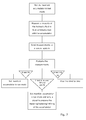
- the invention furthermore relates to a method for measuring the property of the fluid to determine whether refilling of the accumulator of the hydraulic pitch system as described above is necessary, comprising the steps of measuring a property of the fluid, evaluating whether the measurement is above or below a predetermined value, and refilling the accumulator if the measurement is below the predetermined value.
- the invention also relates to a method as described above, comprising the steps of starting a pump for generating a hydraulic pressure in the hydraulic fluid; building up a pressure in the system until a first predetermined pressure; and measuring an initial first fluid pressure and a second fluid pressure after a predetermined period of draining the accumulator, or measuring a period of time where the fluid pressure drops to a predetermined pressure while the accumulator is being drained.
- the invention relates to a method as described above, comprising the steps of comparing the measurement with a predetermined value, and controlling the operation of the wind turbine based on the comparison.
- a wind turbine 3 having a tower 10, a nacelle 11, a hub 8 and rotor blades 2 is mounted to the hub. Furthermore, the wind turbine 3 comprises a hydraulic pitch system for adjusting the pitch angle of the blades 2 in response to the amount of wind and the wind direction so that no damage occurs in the wind turbine 3. The wind turbine 3 also has a control system 9 arranged in the nacelle 11 for controlling the operation of the wind turbine 3.
- the hydraulic pitch system 1 is shown mounted in the hub 8, but the rotor blades 2 have not yet been mounted onto the hub 8.
- the hydraulic pitch system 1 comprises three manifolds 4, one for each rotor blade.
- the manifold 4 is the hydraulic system for one rotor blade and comprises a cylinder 5 and an accumulator 6.
- the cylinder 5 adjusts the pitch angle of the rotor blade 2 in response to wind measurements conducted in another part of the wind turbine 3, and the accumulator 6 absorbs pulsations in the hydraulic system.
- the hydraulic system of each manifold 4 can be seen in Fig. 3 .
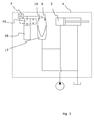
- the accumulator 6 has a chamber 16 comprising gas (not shown) and a chamber 17 comprising liquid (not shown).
- the accumulator 6 is fluidly connected with a refilling container 18 and a testing unit 7 on its gas side. On its liquid side 17, the accumulator is connected to the pitch cylinder.
- the testing unit 7 performs measurements at predetermined intervals, and based on the results of these measurements, the accumulator 6 is refilled when its gas content is below a certain pressure value.
- the refilling chamber 18 When servicing the wind turbine, the refilling chamber 18 is refilled or replaced, and the above described process can take place while the wind turbine is running, thereby substantially increasing the operation time of the wind turbine.
- the service life of the accumulator 6 is substantially increased since the accumulator 6 is refilled continuously and not only when service is performed on the wind turbine. Refilling the accumulator 6 more frequently causes less gas to leak into the liquid side of the accumulator 6, which also prolongs the service life of the accumulator 6.
- the testing unit 7 is mounted on the outside wall of the accumulator 6, and measurements conducted by the testing unit 7 control the opening and closing of the refilling container 18 in order to refill the accumulator 6 as required.
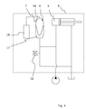
- the testing unit 7 may also comprise a pressure measuring instrument, such as a pressure transducer 20, arranged in fluid communication with the liquid side of the accumulator 6. By having a pressure measuring instrument 20 in fluid communication with the liquid side, measurements from the liquid side can also be used to control the opening and closing of the refilling container 18 in order to refill the accumulator 6 as required.
- the measurements of the liquid side can be compared to the measurements of the gas side of the accumulator 6 so as to determine whether the need for refilling is caused by a leak on the liquid side of the accumulator 6, or if the refilling container 18 is empty.
- the testing unit 7 comprises several measuring instruments arranged both on the liquid side of the accumulator 6 and on the gas side of the accumulator 6.
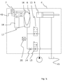
- a pressure controlled valve 40 is arranged in connection with the refilling container, as shown in Figs. 3 and 5 .
- the valve is comprised in the testing unit 7 or the refilling container.
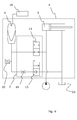
- Each manifold 4 comprises a refilling container 18, however, the hydraulic pitch system 1 may also comprise a common refilling container 19, as shown in Fig. 6 , and a distribution block (not shown) to be able to distribute the gas to each accumulator of a manifold.
- the hydraulic pitch system may furthermore comprise a back-up refilling container (not shown) which automatically replaces the common refilling container 19 or one of the refilling containers 18 in a manifold if one is defective or simply empty.
- the refilling container is a gas cartridge or a gas cylinder.
- the testing unit 7 comprises one or more pressure measuring instruments, such as a piezoelectric sensor, an optical sensor, a magnetic sensor, a capacitive sensor, a potentiometric sensor, a resonance sensor, an acoustic sensor, an ultrasonic sensor, a manometer or a mass control sensor.
- each manifold 4 has a manifold accumulator, and aside from these manifold accumulators, the hydraulic pitch system 1 comprises a common accumulator or a system accumulator 12.
- Each manifold 4 comprises a testing unit 7 which is in fluid communication with the accumulator 6 so as to test each manifold accumulator.
- a manifold accumulator By having a common accumulator 12, a manifold accumulator can be tested without stopping the wind turbine 3. Then, the common accumulator 12 or system accumulator steps in and acts as the manifold accumulator which is being tested. In this way, the operating time of the wind turbine 3 is substantially increased and the number of breakdowns in components in the pitch system 1 can be substantially reduced since the operator is able to replace the accumulators before they break. These replacements can thus take place when the wind turbine 3 is stopped due to other repair work, or the replacements can be done by disconnecting the manifold accumulator to be replaced while the common accumulator is connected and functioning as that manifold accumulator.
- the testing unit 7 comprises a flow constriction means 14, such as a flow control valve, a throttle, a nozzle, a check valve or the like means.
- the testing unit 7 comprises a pressure transducer 20 to continuously measure the pressure drop in a predetermined time interval or periodically in the same predetermined time interval. The pressure may also simply be measured initially and again when the predetermined time interval has passed. If the pressure drop is too high, i.e.
- the accumulator needs to be replaced, or the gas side of the accumulator needs to be refilled. Thus, the accumulator is refilled with gas, and the test is performed again. If the pressure drop is still too high, i.e. if the pressure is too low when the predetermined time period has passed, the accumulator needs to be replaced. Conversely, if the pressure drop is too low, i.e. if the pressure is too high when the predetermined time period has passed, one of the valves may be defective. If the pressure drop is too high, but not high enough for the accumulator to need replacement, the wind turbine 3 is allowed to operate for a limited period of time. The accumulator then needs to be replaced within that limited time period to avoid the wind turbine 3 being set in STOP mode.
- the system may also comprise a relief valve (not shown) so that if the pressure drop is too low, i.e. if the pressure is too high, gas can be let out of the accumulator and the accumulator can be retested. If the pressure is still too high, a valve is defective.
- the manifold accumulator When the manifold accumulator has been tested, it is set in RUN mode if it is allowed to operate. Then, the system accumulator can be used to test another manifold accumulator.
- test results are sent to a control system 9 which may be arranged in the hub 8 or the nacelle 11.
- the evaluation of the measurements is performed in the control system 9. If the test results show that the accumulator 6 needs immediate replacement, the control unit sends a signal to the operator that the wind turbine has been stopped and that a certain manifold accumulator needs replacement before the wind turbine can run again. In the same way, the control system notifies the operator that a certain manifold accumulator needs replacement within a limited time period to avoid the wind turbine being set in STOP mode.
- test results are archived in the control system or sent to a central control system for several wind turbines.
- the measurements made by the testing unit can also be used to predict the use of hydraulic fluid in the hydraulic system.
- valve 13 When a manifold accumulator has been tested with a positive result, the valve 13 is activated to fluidly connect the manifold accumulator again. The system accumulator 12 is then used instead of a second manifold accumulator in a second manifold. The valve 13 in a second manifold is then activated to fluidly disconnect the second accumulator while testing the same.
- the pressure drop of the fluid coming from the accumulator is measured, and the pressure is subsequently increased to the operation pressure again, as shown in Fig. 8 .
- the pressure is increased to a pressure above the operation pressure before the accumulator is drained of fluid during testing, and when the accumulator has been tested, the pressure is increased or decreased to the operation pressure again before the accumulator starts operating again.
- the pressure is increased before the draining takes place, thereby initiating the testing procedure, and when the accumulator test has been performed, the pressure is increased again until it reaches the operation pressure.
- the testing unit 7 comprises a fluid tank and the system pump is activated to increase the pressure.
- the testing unit does not comprise a fluid tank and the pump uses the tank of the pitch system when increasing the pressure.
- the manifold comprises an additional valve 15 arranged downstream of the throttle 14.
- the additional valve 15 may be activated to allow the hydraulic fluid to run to the tank 25.
- the tank 25 may be arranged in the hub 8 or in the nacelle 11.
- a test of the common accumulator is performed. This is done by a testing unit of one of the manifolds or by a separate testing unit fluidly connected with the common accumulator.
- the testing procedure is the same as the procedure mentioned above, and the individual manifold accumulators are only tested if the common accumulator is tested fit to run. If the pressure drop is too high, i.e. if the pressure is too low when the predetermined period of time has passed, and the common accumulator needs to be replaced, the wind turbine is not stopped, but a signal is sent or an alarm is activated to ensure that the common accumulator is replaced as soon as possible.
- the fluid When testing an accumulator, the fluid is drained to the system tank through a throttle 14 or the like flow restriction means.
- the initial pressure is determined, and after a time period of e.g. 10 seconds, the pressure is determined again. In this way, a pressure drop over a period of time can be calculated, and the calculated pressure drop is then compared with level values determining whether the pressure drop is too high or too low.
- the testing unit 7 comprises a timer and a pressure determining instrument.
- the pressure is increased to 30-100 bars above the operation pressure in the hydraulic system, and the testing unit disconnects the manifold accumulator. Then the accumulator is drained from fluid and how long time it takes for the pressure to drop from the increased pressure to the operation pressure is measured. Based upon other testing values, the control system evaluate whether the accumulator is efficient enough to operate, should be replaced in the near future or if the wind turbine needs to be stopped in order to avoid damages on the pitch system or other related components.
- the system accumulator 12 may be fluidly connected to all the manifolds 4 and therefore does not need to be fluidly connected to the manifold when the manifold accumulator is to be tested.
- the common accumulator has to be fluidly connected to a manifold 4 when the accumulator of that manifold is to be tested.
- the common accumulator or system accumulator can act as that manifold accumulator, which increases the operating time of the wind turbine 3 since it does not have to stop. Then, the damaged manifold accumulator can be changed by the service personnel without stopping the wind turbine.
- the hydraulic pitch system 1 has an additional accumulator, meaning that there are two more accumulators than rotor blades. By having this second system accumulator, the pitch system 1 is able to test even though one manifold accumulator has been replaced with a system accumulator.
- the testing unit 7 may comprise a temperature measuring instrument (not shown) or another measuring instrument.
- the other measuring instrument may replace the pressure measuring instrument or be comprised as an additional measuring instrument.
- the measuring instrument may measure any kind of property in the hydraulic fluid, such as the viscosity, flow, velocity, gas/liquid amount, density, temperature or pressure.
- the testing unit 7 may also be able to measure the presence of gas in the fluid in order to detect a leakage of gas in the accumulator.
- the temperature measuring instrument may be a hotwire anemometer, and the flow or velocity measuring instrument may be a sonic anemometer. Being able to measure the temperature enables detection of defective electrical components disposing effect in the fluid before any damage occurs in the components of the wind turbine 3. In the same way, defective components disposing fragments in the fluid in the hydraulic pitch system 1 can be detected before any damage occurs in the components of the wind turbine 3.
- the measuring instrument is positioned outside the wall of the manifold accumulator to measure on the inside of the accumulator by means of an ultrasonic sensor.
- the control system of the testing unit 7 may monitor whether the measurements are within a predetermined parameter range, and if it detects that a measured value is outside the predetermined parameter range, it sends a signal to the operator to activate an alarm device.
- the control system may also send a signal to the testing unit 7 to test the same accumulator again to verify that the accumulator is not just temporally outside the predetermined range.
- the control system 9 may also comprise a plotter device (not shown) for continuously plotting the measurements performed by the testing unit 7.
- a plotter device for continuously plotting the measurements performed by the testing unit 7.
- the valves 13, 15 in the testing unit 7 may be any kind of valve able to regulate the flow to prevent the fluid from flowing between the cylinder 5 and the accumulator 6.
- the valves 13, 15 may be operated manually and/or electronically by the control system. Furthermore, the valves may be activated if the pressure in the accumulator drops too much to start the test.
- the accumulator 6 may be any kind of accumulator, such as a bladder accumulator, a piston accumulator, a diaphragm accumulator or a metal bellow accumulator.
- system accumulator 12 is so large that it is able to absorb the fluctuations of all three manifolds, thereby enabling simultaneous testing of all three manifold accumulators.
- a wind turbine any kind of apparatus able to convert wind power into electricity, such as a wind generator, a wind power unit (WPU) or a wind energy converter (WEC).
- WPU wind power unit
- WEC wind energy converter
Landscapes
- Engineering & Computer Science (AREA)
- Life Sciences & Earth Sciences (AREA)
- Sustainable Development (AREA)
- Sustainable Energy (AREA)
- Chemical & Material Sciences (AREA)
- Combustion & Propulsion (AREA)
- Mechanical Engineering (AREA)
- General Engineering & Computer Science (AREA)
- Physics & Mathematics (AREA)
- Fluid Mechanics (AREA)
- Wind Motors (AREA)
Applications Claiming Priority (1)
| Application Number | Priority Date | Filing Date | Title |
|---|---|---|---|
| DKPA201070305A DK201070305A (en) | 2010-06-30 | 2010-06-30 | A pitch system |
Publications (3)
| Publication Number | Publication Date |
|---|---|
| EP2402604A2 true EP2402604A2 (fr) | 2012-01-04 |
| EP2402604A3 EP2402604A3 (fr) | 2014-06-04 |
| EP2402604B1 EP2402604B1 (fr) | 2017-12-20 |
Family
ID=44281141
Family Applications (1)
| Application Number | Title | Priority Date | Filing Date |
|---|---|---|---|
| EP11172067.8A Active EP2402604B1 (fr) | 2010-06-30 | 2011-06-30 | Dispositif de réglage du pas de l'hélice pour turbine éolienne |
Country Status (3)
| Country | Link |
|---|---|
| EP (1) | EP2402604B1 (fr) |
| DK (1) | DK201070305A (fr) |
| ES (1) | ES2656311T3 (fr) |
Cited By (3)
| Publication number | Priority date | Publication date | Assignee | Title |
|---|---|---|---|---|
| WO2017063654A1 (fr) * | 2015-10-14 | 2017-04-20 | Vestas Wind Systems A/S | Procédé pour commander une force de pas hydraulique |
| ITUB20161185A1 (it) * | 2016-03-01 | 2017-09-01 | Magneti Marelli Spa | Procedimento per verificare un'eventuale riduzione del livello di olio in un sistema di attuazione idraulico, in particolare un sistema di attuazione idraulico per trasmissione di veicolo. |
| EP3561296A1 (fr) * | 2018-04-26 | 2019-10-30 | Siemens Gamesa Renewable Energy A/S | Outil d'échange d'accumulateur hydraulique |
Family Cites Families (6)
| Publication number | Priority date | Publication date | Assignee | Title |
|---|---|---|---|---|
| DE2158497A1 (de) * | 1971-11-25 | 1973-05-30 | Otto Eckerle | Druckspeicher fuer fluessigkeiten oder gase |
| DD119848A1 (fr) * | 1975-06-20 | 1976-05-12 | ||
| DE3224136A1 (de) * | 1982-06-29 | 1983-12-29 | Korkmaz, Feridun, Dr.-Ing., 1000 Berlin | Mess- und ueberwachungssystem fuer hydrospeicher |
| US4487226A (en) * | 1982-08-12 | 1984-12-11 | Vsi Corporation | Failure sensing hydraulic accumulator and system |
| US4792281A (en) * | 1986-11-03 | 1988-12-20 | Northern Power Systems, Inc. | Wind turbine pitch control hub |
| US20110012353A1 (en) * | 2008-07-04 | 2011-01-20 | Mitsubishi Heavy Industries, Ltd. | Wind power generator |
-
2010
- 2010-06-30 DK DKPA201070305A patent/DK201070305A/en not_active Application Discontinuation
-
2011
- 2011-06-30 EP EP11172067.8A patent/EP2402604B1/fr active Active
- 2011-06-30 ES ES11172067.8T patent/ES2656311T3/es active Active
Non-Patent Citations (1)
| Title |
|---|
| None |
Cited By (10)
| Publication number | Priority date | Publication date | Assignee | Title |
|---|---|---|---|---|
| WO2017063654A1 (fr) * | 2015-10-14 | 2017-04-20 | Vestas Wind Systems A/S | Procédé pour commander une force de pas hydraulique |
| CN108368829A (zh) * | 2015-10-14 | 2018-08-03 | 维斯塔斯风力系统集团公司 | 控制液压变桨力系统的方法 |
| US10920747B2 (en) | 2015-10-14 | 2021-02-16 | Vestas Wind Systems A/S | Method for controlling hydraulic pitch force system |
| ITUB20161185A1 (it) * | 2016-03-01 | 2017-09-01 | Magneti Marelli Spa | Procedimento per verificare un'eventuale riduzione del livello di olio in un sistema di attuazione idraulico, in particolare un sistema di attuazione idraulico per trasmissione di veicolo. |
| EP3214320A1 (fr) * | 2016-03-01 | 2017-09-06 | Magneti Marelli S.p.A. | Procédé pour évaluer une réduction possible du niveau d'huile dans un système d'actionnement hydraulique, en particulier un système d'actionnement hydraulique d'une transmission de véhicule |
| EP3561296A1 (fr) * | 2018-04-26 | 2019-10-30 | Siemens Gamesa Renewable Energy A/S | Outil d'échange d'accumulateur hydraulique |
| WO2019206662A1 (fr) * | 2018-04-26 | 2019-10-31 | Siemens Gamesa Renewable Energy A/S | Outil d'échange d'accumulateur hydraulique |
| CN111989484A (zh) * | 2018-04-26 | 2020-11-24 | 西门子歌美飒可再生能源公司 | 液压蓄积器更换工具 |
| US11713745B2 (en) | 2018-04-26 | 2023-08-01 | Siemens Gamesa Renewable Energy A/S | Hydraulic accumulator exchange tool |
| CN111989484B (zh) * | 2018-04-26 | 2023-12-08 | 西门子歌美飒可再生能源公司 | 液压蓄积器更换工具 |
Also Published As
| Publication number | Publication date |
|---|---|
| EP2402604B1 (fr) | 2017-12-20 |
| EP2402604A3 (fr) | 2014-06-04 |
| DK201070305A (en) | 2011-07-01 |
| ES2656311T3 (es) | 2018-02-26 |
Similar Documents
| Publication | Publication Date | Title |
|---|---|---|
| EP2402596B1 (fr) | Dispositif de réglage du pas de l'hélice pour turbine éolienne | |
| US8434360B2 (en) | System and method for detecting ice on a wind turbine rotor blade | |
| US10648605B2 (en) | Water hammer prevention system using operation state analysis algorithm | |
| US8033788B2 (en) | Method for determining fatigue load of a wind turbine and for fatigue load control, and wind turbines therefor | |
| EP2270342B1 (fr) | Système de détection de fuite dans une éolienne | |
| US10794362B2 (en) | Method and system for diagnosing wind turbine power generating apparatus | |
| JP2013170566A (ja) | 風力発電装置の監視方法及びシステム | |
| US9587636B2 (en) | Method and system for monitoring the operational state of a pump | |
| EP2402604B1 (fr) | Dispositif de réglage du pas de l'hélice pour turbine éolienne | |
| CN108760187B (zh) | 叶片开裂状态监测方法、监测系统及叶片 | |
| EP3020961B1 (fr) | Procédé de fonctionnement d'un générateur de turbine éolienne | |
| KR101723316B1 (ko) | 모니터링되는 부품 접속부,풍력 발전 시스템 및 접속된 상태에서 부품 접속부의 의도치 않은 해제에 대해서 부품 접속부를 모니터링하기 위한 방법 | |
| CN106894954A (zh) | 具有各种传感器测试的风力涡轮机诊断装置 | |
| EP3642481B1 (fr) | Procédé de détermination de récurrence de charge dans le sens de la traînée de pale d'éolienne | |
| CN113412347A (zh) | 冲扫系统及其监测方法 | |
| KR20210108168A (ko) | 머신러닝 기반의 펌프 고장 진단 모니터링 방법 | |
| CN110300857B (zh) | 检测在液压缸的区段之间的油泄漏的方法和布置结构 | |
| CN201714747U (zh) | 一种液压流量报警装置 | |
| CN105508146B (zh) | 风力发电机组的偏航测试系统 | |
| CN105332862B (zh) | 用于检测风力发电机组工作状态的方法、装置和系统 | |
| KR101708848B1 (ko) | 풍력발전기 블레이드 진단시스템 | |
| Carroll et al. | Availability improvements from condition monitoring systems and performance based maintenance contracts | |
| CN206655681U (zh) | 抽油机动态自动调平衡装置 | |
| EP4353966A1 (fr) | Surveillance automatique d'un amortisseur rempli de fluide d'une éolienne | |
| KR101372489B1 (ko) | 스마트 센서를 이용한 원전 저압 터빈 온라인 감시 시스템 |
Legal Events
| Date | Code | Title | Description |
|---|---|---|---|
| AK | Designated contracting states |
Kind code of ref document: A2 Designated state(s): AL AT BE BG CH CY CZ DE DK EE ES FI FR GB GR HR HU IE IS IT LI LT LU LV MC MK MT NL NO PL PT RO RS SE SI SK SM TR |
|
| AX | Request for extension of the european patent |
Extension state: BA ME |
|
| PUAI | Public reference made under article 153(3) epc to a published international application that has entered the european phase |
Free format text: ORIGINAL CODE: 0009012 |
|
| PUAL | Search report despatched |
Free format text: ORIGINAL CODE: 0009013 |
|
| AK | Designated contracting states |
Kind code of ref document: A3 Designated state(s): AL AT BE BG CH CY CZ DE DK EE ES FI FR GB GR HR HU IE IS IT LI LT LU LV MC MK MT NL NO PL PT RO RS SE SI SK SM TR |
|
| AX | Request for extension of the european patent |
Extension state: BA ME |
|
| RIC1 | Information provided on ipc code assigned before grant |
Ipc: F03D 11/00 20060101AFI20140425BHEP Ipc: F03D 7/00 20060101ALI20140425BHEP Ipc: F03D 7/02 20060101ALI20140425BHEP |
|
| 17P | Request for examination filed |
Effective date: 20141201 |
|
| RBV | Designated contracting states (corrected) |
Designated state(s): AL AT BE BG CH CY CZ DE DK EE ES FI FR GB GR HR HU IE IS IT LI LT LU LV MC MK MT NL NO PL PT RO RS SE SI SK SM TR |
|
| RAP1 | Party data changed (applicant data changed or rights of an application transferred) |
Owner name: VESTAS WIND SYSTEMS A/S |
|
| REG | Reference to a national code |
Ref country code: DE Ref legal event code: R079 Ref document number: 602011044301 Country of ref document: DE Free format text: PREVIOUS MAIN CLASS: F03D0011000000 Ipc: F03D0007000000 |
|
| GRAP | Despatch of communication of intention to grant a patent |
Free format text: ORIGINAL CODE: EPIDOSNIGR1 |
|
| RIC1 | Information provided on ipc code assigned before grant |
Ipc: F03D 7/02 20060101ALI20170922BHEP Ipc: F03D 17/00 20160101ALI20170922BHEP Ipc: F03D 7/00 20060101AFI20170922BHEP |
|
| GRAS | Grant fee paid |
Free format text: ORIGINAL CODE: EPIDOSNIGR3 |
|
| INTG | Intention to grant announced |
Effective date: 20171012 |
|
| INTG | Intention to grant announced |
Effective date: 20171017 |
|
| GRAA | (expected) grant |
Free format text: ORIGINAL CODE: 0009210 |
|
| AK | Designated contracting states |
Kind code of ref document: B1 Designated state(s): AL AT BE BG CH CY CZ DE DK EE ES FI FR GB GR HR HU IE IS IT LI LT LU LV MC MK MT NL NO PL PT RO RS SE SI SK SM TR |
|
| REG | Reference to a national code |
Ref country code: GB Ref legal event code: FG4D |
|
| RIN1 | Information on inventor provided before grant (corrected) |
Inventor name: NIELSEN, JENS BREDAL |
|
| REG | Reference to a national code |
Ref country code: CH Ref legal event code: EP |
|
| REG | Reference to a national code |
Ref country code: IE Ref legal event code: FG4D |
|
| REG | Reference to a national code |
Ref country code: AT Ref legal event code: REF Ref document number: 956638 Country of ref document: AT Kind code of ref document: T Effective date: 20180115 |
|
| REG | Reference to a national code |
Ref country code: DE Ref legal event code: R096 Ref document number: 602011044301 Country of ref document: DE |
|
| REG | Reference to a national code |
Ref country code: ES Ref legal event code: FG2A Ref document number: 2656311 Country of ref document: ES Kind code of ref document: T3 Effective date: 20180226 |
|
| REG | Reference to a national code |
Ref country code: NL Ref legal event code: MP Effective date: 20171220 |
|
| PG25 | Lapsed in a contracting state [announced via postgrant information from national office to epo] |
Ref country code: FI Free format text: LAPSE BECAUSE OF FAILURE TO SUBMIT A TRANSLATION OF THE DESCRIPTION OR TO PAY THE FEE WITHIN THE PRESCRIBED TIME-LIMIT Effective date: 20171220 Ref country code: SE Free format text: LAPSE BECAUSE OF FAILURE TO SUBMIT A TRANSLATION OF THE DESCRIPTION OR TO PAY THE FEE WITHIN THE PRESCRIBED TIME-LIMIT Effective date: 20171220 Ref country code: NO Free format text: LAPSE BECAUSE OF FAILURE TO SUBMIT A TRANSLATION OF THE DESCRIPTION OR TO PAY THE FEE WITHIN THE PRESCRIBED TIME-LIMIT Effective date: 20180320 Ref country code: LT Free format text: LAPSE BECAUSE OF FAILURE TO SUBMIT A TRANSLATION OF THE DESCRIPTION OR TO PAY THE FEE WITHIN THE PRESCRIBED TIME-LIMIT Effective date: 20171220 |
|
| REG | Reference to a national code |
Ref country code: LT Ref legal event code: MG4D |
|
| REG | Reference to a national code |
Ref country code: AT Ref legal event code: MK05 Ref document number: 956638 Country of ref document: AT Kind code of ref document: T Effective date: 20171220 |
|
| PG25 | Lapsed in a contracting state [announced via postgrant information from national office to epo] |
Ref country code: LV Free format text: LAPSE BECAUSE OF FAILURE TO SUBMIT A TRANSLATION OF THE DESCRIPTION OR TO PAY THE FEE WITHIN THE PRESCRIBED TIME-LIMIT Effective date: 20171220 Ref country code: HR Free format text: LAPSE BECAUSE OF FAILURE TO SUBMIT A TRANSLATION OF THE DESCRIPTION OR TO PAY THE FEE WITHIN THE PRESCRIBED TIME-LIMIT Effective date: 20171220 Ref country code: RS Free format text: LAPSE BECAUSE OF FAILURE TO SUBMIT A TRANSLATION OF THE DESCRIPTION OR TO PAY THE FEE WITHIN THE PRESCRIBED TIME-LIMIT Effective date: 20171220 Ref country code: BG Free format text: LAPSE BECAUSE OF FAILURE TO SUBMIT A TRANSLATION OF THE DESCRIPTION OR TO PAY THE FEE WITHIN THE PRESCRIBED TIME-LIMIT Effective date: 20180320 Ref country code: GR Free format text: LAPSE BECAUSE OF FAILURE TO SUBMIT A TRANSLATION OF THE DESCRIPTION OR TO PAY THE FEE WITHIN THE PRESCRIBED TIME-LIMIT Effective date: 20180321 |
|
| REG | Reference to a national code |
Ref country code: FR Ref legal event code: PLFP Year of fee payment: 8 |
|
| PG25 | Lapsed in a contracting state [announced via postgrant information from national office to epo] |
Ref country code: NL Free format text: LAPSE BECAUSE OF FAILURE TO SUBMIT A TRANSLATION OF THE DESCRIPTION OR TO PAY THE FEE WITHIN THE PRESCRIBED TIME-LIMIT Effective date: 20171220 |
|
| PG25 | Lapsed in a contracting state [announced via postgrant information from national office to epo] |
Ref country code: EE Free format text: LAPSE BECAUSE OF FAILURE TO SUBMIT A TRANSLATION OF THE DESCRIPTION OR TO PAY THE FEE WITHIN THE PRESCRIBED TIME-LIMIT Effective date: 20171220 Ref country code: CY Free format text: LAPSE BECAUSE OF FAILURE TO SUBMIT A TRANSLATION OF THE DESCRIPTION OR TO PAY THE FEE WITHIN THE PRESCRIBED TIME-LIMIT Effective date: 20171220 Ref country code: CZ Free format text: LAPSE BECAUSE OF FAILURE TO SUBMIT A TRANSLATION OF THE DESCRIPTION OR TO PAY THE FEE WITHIN THE PRESCRIBED TIME-LIMIT Effective date: 20171220 Ref country code: SK Free format text: LAPSE BECAUSE OF FAILURE TO SUBMIT A TRANSLATION OF THE DESCRIPTION OR TO PAY THE FEE WITHIN THE PRESCRIBED TIME-LIMIT Effective date: 20171220 |
|
| PG25 | Lapsed in a contracting state [announced via postgrant information from national office to epo] |
Ref country code: PL Free format text: LAPSE BECAUSE OF FAILURE TO SUBMIT A TRANSLATION OF THE DESCRIPTION OR TO PAY THE FEE WITHIN THE PRESCRIBED TIME-LIMIT Effective date: 20171220 Ref country code: SM Free format text: LAPSE BECAUSE OF FAILURE TO SUBMIT A TRANSLATION OF THE DESCRIPTION OR TO PAY THE FEE WITHIN THE PRESCRIBED TIME-LIMIT Effective date: 20171220 Ref country code: RO Free format text: LAPSE BECAUSE OF FAILURE TO SUBMIT A TRANSLATION OF THE DESCRIPTION OR TO PAY THE FEE WITHIN THE PRESCRIBED TIME-LIMIT Effective date: 20171220 Ref country code: AT Free format text: LAPSE BECAUSE OF FAILURE TO SUBMIT A TRANSLATION OF THE DESCRIPTION OR TO PAY THE FEE WITHIN THE PRESCRIBED TIME-LIMIT Effective date: 20171220 Ref country code: IS Free format text: LAPSE BECAUSE OF FAILURE TO SUBMIT A TRANSLATION OF THE DESCRIPTION OR TO PAY THE FEE WITHIN THE PRESCRIBED TIME-LIMIT Effective date: 20180420 Ref country code: IT Free format text: LAPSE BECAUSE OF FAILURE TO SUBMIT A TRANSLATION OF THE DESCRIPTION OR TO PAY THE FEE WITHIN THE PRESCRIBED TIME-LIMIT Effective date: 20171220 |
|
| REG | Reference to a national code |
Ref country code: DE Ref legal event code: R097 Ref document number: 602011044301 Country of ref document: DE |
|
| PLBE | No opposition filed within time limit |
Free format text: ORIGINAL CODE: 0009261 |
|
| STAA | Information on the status of an ep patent application or granted ep patent |
Free format text: STATUS: NO OPPOSITION FILED WITHIN TIME LIMIT |
|
| 26N | No opposition filed |
Effective date: 20180921 |
|
| PG25 | Lapsed in a contracting state [announced via postgrant information from national office to epo] |
Ref country code: DK Free format text: LAPSE BECAUSE OF FAILURE TO SUBMIT A TRANSLATION OF THE DESCRIPTION OR TO PAY THE FEE WITHIN THE PRESCRIBED TIME-LIMIT Effective date: 20171220 |
|
| REG | Reference to a national code |
Ref country code: CH Ref legal event code: PL |
|
| PG25 | Lapsed in a contracting state [announced via postgrant information from national office to epo] |
Ref country code: SI Free format text: LAPSE BECAUSE OF FAILURE TO SUBMIT A TRANSLATION OF THE DESCRIPTION OR TO PAY THE FEE WITHIN THE PRESCRIBED TIME-LIMIT Effective date: 20171220 |
|
| REG | Reference to a national code |
Ref country code: BE Ref legal event code: MM Effective date: 20180630 |
|
| PG25 | Lapsed in a contracting state [announced via postgrant information from national office to epo] |
Ref country code: LU Free format text: LAPSE BECAUSE OF NON-PAYMENT OF DUE FEES Effective date: 20180630 Ref country code: MC Free format text: LAPSE BECAUSE OF FAILURE TO SUBMIT A TRANSLATION OF THE DESCRIPTION OR TO PAY THE FEE WITHIN THE PRESCRIBED TIME-LIMIT Effective date: 20171220 |
|
| REG | Reference to a national code |
Ref country code: IE Ref legal event code: MM4A |
|
| PG25 | Lapsed in a contracting state [announced via postgrant information from national office to epo] |
Ref country code: IE Free format text: LAPSE BECAUSE OF NON-PAYMENT OF DUE FEES Effective date: 20180630 Ref country code: CH Free format text: LAPSE BECAUSE OF NON-PAYMENT OF DUE FEES Effective date: 20180630 Ref country code: LI Free format text: LAPSE BECAUSE OF NON-PAYMENT OF DUE FEES Effective date: 20180630 |
|
| PG25 | Lapsed in a contracting state [announced via postgrant information from national office to epo] |
Ref country code: BE Free format text: LAPSE BECAUSE OF NON-PAYMENT OF DUE FEES Effective date: 20180630 |
|
| PG25 | Lapsed in a contracting state [announced via postgrant information from national office to epo] |
Ref country code: MT Free format text: LAPSE BECAUSE OF NON-PAYMENT OF DUE FEES Effective date: 20180630 |
|
| PG25 | Lapsed in a contracting state [announced via postgrant information from national office to epo] |
Ref country code: TR Free format text: LAPSE BECAUSE OF FAILURE TO SUBMIT A TRANSLATION OF THE DESCRIPTION OR TO PAY THE FEE WITHIN THE PRESCRIBED TIME-LIMIT Effective date: 20171220 |
|
| PG25 | Lapsed in a contracting state [announced via postgrant information from national office to epo] |
Ref country code: HU Free format text: LAPSE BECAUSE OF FAILURE TO SUBMIT A TRANSLATION OF THE DESCRIPTION OR TO PAY THE FEE WITHIN THE PRESCRIBED TIME-LIMIT; INVALID AB INITIO Effective date: 20110630 Ref country code: PT Free format text: LAPSE BECAUSE OF FAILURE TO SUBMIT A TRANSLATION OF THE DESCRIPTION OR TO PAY THE FEE WITHIN THE PRESCRIBED TIME-LIMIT Effective date: 20171220 |
|
| PG25 | Lapsed in a contracting state [announced via postgrant information from national office to epo] |
Ref country code: MK Free format text: LAPSE BECAUSE OF NON-PAYMENT OF DUE FEES Effective date: 20171220 |
|
| PG25 | Lapsed in a contracting state [announced via postgrant information from national office to epo] |
Ref country code: AL Free format text: LAPSE BECAUSE OF FAILURE TO SUBMIT A TRANSLATION OF THE DESCRIPTION OR TO PAY THE FEE WITHIN THE PRESCRIBED TIME-LIMIT Effective date: 20171220 |
|
| P01 | Opt-out of the competence of the unified patent court (upc) registered |
Effective date: 20230521 |
|
| PGFP | Annual fee paid to national office [announced via postgrant information from national office to epo] |
Ref country code: FR Payment date: 20230622 Year of fee payment: 13 Ref country code: DE Payment date: 20230627 Year of fee payment: 13 |
|
| PGFP | Annual fee paid to national office [announced via postgrant information from national office to epo] |
Ref country code: GB Payment date: 20230620 Year of fee payment: 13 Ref country code: ES Payment date: 20230721 Year of fee payment: 13 |