EP2401931A2 - Glove and method for producing the same - Google Patents
Glove and method for producing the same Download PDFInfo
- Publication number
- EP2401931A2 EP2401931A2 EP11172164A EP11172164A EP2401931A2 EP 2401931 A2 EP2401931 A2 EP 2401931A2 EP 11172164 A EP11172164 A EP 11172164A EP 11172164 A EP11172164 A EP 11172164A EP 2401931 A2 EP2401931 A2 EP 2401931A2
- Authority
- EP
- European Patent Office
- Prior art keywords
- glove
- coating layer
- air bubble
- back portion
- projection
- Prior art date
- Legal status (The legal status is an assumption and is not a legal conclusion. Google has not performed a legal analysis and makes no representation as to the accuracy of the status listed.)
- Granted
Links
Images


Classifications
-
- A—HUMAN NECESSITIES
- A41—WEARING APPAREL
- A41D—OUTERWEAR; PROTECTIVE GARMENTS; ACCESSORIES
- A41D19/00—Gloves
- A41D19/0055—Plastic or rubber gloves
- A41D19/0082—Details
- A41D19/0096—Means for resisting mechanical agressions, e.g. cutting or piercing
-
- A—HUMAN NECESSITIES
- A41—WEARING APPAREL
- A41D—OUTERWEAR; PROTECTIVE GARMENTS; ACCESSORIES
- A41D19/00—Gloves
- A41D19/015—Protective gloves
- A41D19/01505—Protective gloves resistant to mechanical aggressions, e.g. cutting. piercing
Definitions
- the present invention relates to a glove having excellent moisture permeability and abrasion resistance of a back portion, and more specifically, to a glove which, by forming a coating layer having excellent moisture permeability and abrasion resistance on a back portion which tends to be damaged due to rubbing or scratching, does not bring about heat trapped and a steamy condition in a glove to provide an excellent feel when wearing and can further protect the back portion from breakages due to rubbing or scratching or from perforations or damages due to sparks generated in a metal cutting work, and a method of producing the same.
- a glove in which a coating layer is provided by sticking or sewing a synthetic leather to a palm portion of a glove made of fibers and a glove, in which a palm portion is covered with resin or rubber and a back portion is not provided with these coating layers to secure air permeability of a base material made of fibers, are used.
- a glove for sporting in which a palm portion is composed of a natural leather or a synthetic leather and the whole back of the hand including finger bags is composed of a fabric
- a glove for sporting in which the whole back of the hand including finger bags in a glove main body is configured so as to be a two-layered structure in which a chemical fiber fabric is disposed on an inner side and a cotton fabric is disposed on an outer side, is proposed (for example, JP-A-11-290497 ).
- a slip resistant glove in which a foam layer composed of a thermoplastic resin or rubber is formed on the glove base material made of fibers and the surface of the foam layer has a projection and depression shape, in which the foam layer is mechanically foamed and hot pressed in a semi-crosslinked or gelled state to be provided with projections and depressions on the surface, and a depression portion of the foam layer is compressed in such a way that an air bubble content is 10 to 90% by volume with respect to that of a projection portion, and many openings being the impressions of air bubbles are formed at the surface of the projection portion, is proposed (for example, Japanese Patent Publication No. 4242338 ).
- a working glove which is characterized in that a slip resistant coating is formed by coating the surface of a glove main body formed by sewing leather as a material with a synthetic rubber and the synthetic rubber is a copolymer of butadiene and styrene or a copolymer of butadiene and acrylonitrile, which is excellent in oil resistance, acid resistance and alkali resistance (for example, JP-A-7-278923 ).
- the glove since the whole back portion of the glove described in JP-A-11-290497 is composed of fabric, the glove has a problem that the glove is inferior in abrasion resistance and a back portion, which easily suffers from breakages due to rubbing or scratching, particularly fingertips and portions from the fingertips to the first joints, the second joints and the third joints (joints between fingers and backs, the same applies hereinafter) is apt to undergo straggling or breakages in fibers due to rubbing or scratching. Furthermore, the gloves have a problem that the back portion of the glove is readily perforated, for example, due to sparks generated in a metal cutting work because of low strength so that they cannot provide sufficient protection.
- the glove described in Japanese Patent Publication No. 4242338 mainly aims at a slip resistant effect, and therefore in gloves shown in examples, a foam layer is provided for only a palm portion which is brought into contact with an object when gripping the object.
- the back portion of the glove is still composed of a base material made of fibers in these examples, and therefore, the glove is inferior in abrasion resistance, and has problems that as with the gloves in JP-A-11-290497 , the back portion is apt to undergo straggling or breakages, and is readily perforated or damaged, for example, due to sparks generated in a metal cutting work because of low strength and cannot provide sufficient protection.
- the moisture permeability or abrasion resistance of a foam layer of the back portion is not considered at all, and furthermore, any contrivance concerning fingertips, the first joints, the second joints and the third joints of the back portion which easily causes breakages due to rubbing or scratching of the back portion is not considered at all.
- the present invention was made in order to solve the above-mentioned problems, and is characterized by the following items.
- the glove of the present invention is provided with a coating layer which is composed of rubber containing air bubbles and formed at least on a back portion, it has good moisture permeability and abrasion resistance of a back portion, does not cause a trapping of heat and a steamy condition in the glove to provide an excellent feel upon wearing, hardly cause breakages due to rubbing or scratching and is hardly perforated, for example, due to sparks generated in a metal cutting work and is superior in protection performance.
- the glove of the present invention is characterized in that a coating layer of rubber containing air bubbles is formed at least on the surface of a back portion of a glove base material made of fibers, the moisture permeability of the coating layer of the back portion ranges from 1000 to 9000 g/m 2 ⁇ 24 hrs in terms of a measured value according to JIS L 1099 A-1 method (calcium chloride method), and the wear loss of the coating layer of the back portion is 40 mg or less in terms of a value measured after 100 revolutions by use of a tester, Nu-Martindale Abrasion and Pilling Tester, specified by EN ISO 12947-1, according to the European Standard EN 388; 2003.
- the glove of the present invention requires that the moisture permeability of the coating layer of the back portion ranges from 1000 to 9000 g/m 2 ⁇ 24 hrs in terms of a measured value according to JIS L 1099 A-1 method (calcium chloride method).
- the moisture permeability is less than 1000 g/m 2 ⁇ 24 hrs, the moisture permeability of the coating layer is insufficient and the problems of heat trapped and a steamy condition in a glove are not adequately solved.
- the moisture permeability is more than 9000 g/m 2 ⁇ 24 hrs, the abrasion resistance of the coating layer is insufficient.
- the glove of the present invention requires that the wear loss of the coating layer of the back portion is 40 mg or less in terms of a value measured after 100 revolutions by use of a tester, Nu-Martindale Abrasion and Pilling Tester, specified by EN ISO 12947-1, according to the European Standard EN 388; 2003.
- the wear loss is more than 40 mg, the abrasion resistance of the coating layer is insufficient and breakage of the coating layer due to rubbing or scratching cannot be adequately prevented.
- the average air bubble content of the coating layer is 12 to 85%.
- moisture permeability tends to be insufficient
- abrasion resistance tends to be insufficient.
- the coating layer of the back portion particularly, nail portions, the first joint portions, the second joint portions and the third joint portions of fingers, which easily undergo breakages due to rubbing or scratching, have a wear loss of 7 mg or less.
- these portions hardly undergo breakage even when these portions are brought into contact with metal portions, etc., rubbed or scratched during works, and can further prevent the trouble that these portions are perforated due to sparks generated in metal cutting works. Therefore, gloves having even more excellent protection performance can be attained.
- the average air bubble contents of the coating layers of these portions are preferably 0 to 10%.
- the glove base material made of fibers used in the present invention is made by use of natural fibers or chemical fibers, such as cotton, wool, polyester, polyamide (nylon), acryl, aramide, reinforced polyethylene or the like.
- a stretching rate per a unit area of the glove base material made of fibers is usually about 150 to 650%.
- the stretching rate is the maximum enlarging rate when simultaneously stretching the base material longitudinally and laterally. If the stretching rate of the glove base material made of fibers is small, wrinkles, particularly, deep wrinkles in a palm and a thumb, occur in a product prepared after the glove base material made of fibers is released from a hand mold for immersion and put on a hand mold for setting used in hot pressing, and cured vulcanized).
- a knitted or sewed glove base material containing polyurethane elastic fibers in which the stretching rate is imparted to fibers is also used.
- the glove base material made of fibers is dyed or purified as required.
- Examples of the rubber used in the present invention include natural rubber, homopolymers or copolymers such as isoprene, chloroprene, acrylic ester rubber, styrene-butadiene copolymers, acrylonitrile-butadiene copolymers, polyurethane, butyl rubber, polybutadiene rubber and silicone rubber, copolymers containing 10% by weight or less of a carboxyl-modified group, and those blended with the copolymers.
- natural rubber includes not only natural rubber alone, but also a natural rubber-methylmethacrylate copolymer, epoxy-modified natural rubber copolymer, and the like.
- acrylic ester rubber includes homopolymers or copolymers such as n-butyl acrylate, n-butyl methacrylate, iso-butyl acrylate, iso-butyl methacrylate, ethyl acrylate, 2-ethylhexyl acrylate, 2-ethylhexyl methacrylate, iso-propyl acrylate and iso-propyl methacrylate, which contain acrylonitrile, methyl methacrylate, allyl methacrylate, N-methylol acrylamide, acrylic acid, methacrylic acid, or the like.
- a crosslinking agent e.g., a crosslinking agent, a vulcanization accelerator, an antioxidant, a thickener or the like, and a foaming agent or a foam stabilizer can be added to the rubber.
- foaming agent examples include sodium sulfosuccinate based surfactants, alkylmonoamide disodium sulfosuccinate, potassium oleate, castor oil potassium, sodium dodecylbenzenesulfonate, and the like, and these can be used singly or in combination of two or more.
- foam stabilizer examples include ammoniumstearate, peptide, sodium alkyldipropionate, and the like, and these can be used singly or in combination of two or more.
- Alkyl includes lauryl, octyl, stearyl, and the like.
- an air bubble stabilizer for a coating layer if 15 to 50 parts by weight of 2,2,4-trimethyl-1,3-pentanediolmonoisobutylate is added to 100 parts by weight of rubber, processability is improved which is preferable.
- known chemical foaming agents such as toluenesulfonyl hydrazide, pp'oxybis(benzosulfonyl hydrazide), azodicarbonamide and azobisisobutylonitrile, or microcapsules may be further added to reduce the number of open holes for the purpose of preventing absorption of oils or chemicals to the surface of the coating layer.
- particles of acryl, urethane, natural rubber powder, EVA powder, PVC, or NBR may be further added in order to increase a solid content to enhance abrasion resistance.
- the glove of the present invention can be prepared by forming a rubber coating layer including air bubbles at least on a back portion of a glove base material made of fibers by use of a rubber blended solution including air bubbles, then hot pressing the coating layer.
- a glove base material made of fibers is put on a hand mold for immersion.
- a ceramic hand mold, an aluminum alloy hand mold or the like are suitably used, and a hand mold having a configuration in which fingers from a thumb to a little finger are arranged linearly is preferable.
- the glove base material made of fibers is put on the hand mold for immersion preheated to 50 to 70°C, and immersed in, for example, methanol containing calcium nitrate or a warm water bath of a coagulant solution, adjusted to 50 to 70°C, which contains calcium nitrate.
- the content of the coagulant is preferably adjusted in such a way that a rubber blended solution partially penetrates into the glove base material made of fibers in order to avoid the deterioration of touch feeling.
- the immersed hand mold with the glove base material made of fibers put thereon which has been immersed in the warm water bath of a coagulant solution, is immersed in a bath of a rubber blended solution including air bubbles.
- immersion generally, a method of immersing a glove vertically from a fingertip to a wrist is adopted.
- the blended solution is mechanically foamed with a bubbling machine or a mixer.
- the average air bubble content of the blended solution is preferably adjusted to 7 to 88% by volume, more preferably 9 to 61% by volume.
- the average air bubble content (% by volume) of the blended solution is determined by the following method.
- the average air bubble diameter of the blended solution is preferably 10 to 200 ⁇ m, more preferably 10 to 100 ⁇ m.
- the average air bubble diameter of 10 to 200 ⁇ m increases when a coating layer is formed and hot pressed, and therefore, the average air bubble diameter of the coating layer becomes approximately 30 to 400 ⁇ m.
- the average air bubble diameter of the coating layer is important for design, and when the average air bubble diameter is more than 400 ⁇ m, the design tends to be impaired. Accordingly, an upper limit of the average air bubble diameter of the blended solution is preferably approximately 200 ⁇ m.
- the blended solution having the average air bubble diameter of 10 to 200 ⁇ m can be obtained by exerting shear on the blended solution with a high-speed mixer of about 600 to 1200 rpm or a bubbling machine.
- the average air bubble diameter ( ⁇ m) of the blended solution is measured by the following method.
- the glove immersed in the bath of a rubber blended solution including air bubbles is pulled out from the blended solution, and then is dried at 60 to 95°C by heating to be semi-cured (semi-gelled).
- the average air bubble content of the semi-cured coating layer is 22 to 89%, preferably 26 to 64%. This average air bubble content can be adjusted by the concentration of solid matter in the the blended solution and the viscosity of the blended solution, or a foam stabilizer.
- the glove is leached by water washing and hot pressed. By hot pressing, a part of the air bubbles in the coating layer is crushed and the air bubbles can be made to communicate with one another to increase the moisture permeability.
- the coating layer can be preferably hot pressed by adjusting the water content of the coating layer before hot pressing to 20 to 170% by weight. Particularly when the coating layer is provided with a projection and depression pattern through hot pressing, the projection and depression pattern can be beautifully formed.
- the water content (% by weight) in the coating layer before hot pressing is calculated from the following equation.
- a pressing plate having a projection and depression pattern (hereinafter, referred to as a projection and depression plate) is used.
- the projection and depression plate is used for the pressing plate on the back side and a pressing plate without a projection and depression pattern (hereinafter, referred to as a projection plate) is used for the pressing plate on the palm side. Further, when the projection and depression pattern is used on both of the back side and the palm side, the projection and depression plate is used for both of the back side and the palm side.
- the glove in which a coating layer is formed is removed from the hand mold for immersion, put on a flat mold again, and hot pressed as with the above method. Further, when hot pressing is carried out from both of the back side and the palm side of the glove, pressing can be performed at a uniform pressure by using a female mold composed of a projection and depression plate or a projection plate prepared in conformity with the configuration of the hand mold for immersion. In this case, hot pressing can be applied up to a side of the glove, and when the female mold composed of a projection and depression plate is used, a projection and depression pattern is beautifully formed up to a side of the glove.
- the depth of projection and depression (difference in level between the projection and the depression) of the projection and depression plate is preferably in a range from about 0.1 mm to about 1.2 mm, and more preferably about 0.3 mm to about 1.0 mm from the viewpoint of a grip force and design.
- the depth of the projection plate without having a projection and depression pattern is the same as above.
- a shape of the projection and depression pattern of the projection and depression plate is not particularly limited, and examples of the shape include a variety of geometric patterns such as a circle, a shape of an ellipse, a rectangle, a polygonal shape, and the like, and infinite patterns (See Fig. 2 ), and when these are arranged regularly or irregularly, not only abrasion resistance is improved, but also a grip force is improved and design is enhanced.
- the coating layer is hot pressed so that its average air bubble content is 12 to 85%, preferably 15 to 60%.
- the average air bubble content is less than 12%, moisture permeability may be insufficient, and when the average air bubble content is more than 85%, abrasion resistance may be insufficient, and therefore it becomes difficult to obtain a coating layer in which the desired moisture permeability is 1000 to 9000 g/m 2 ⁇ 24 hrs and the desired wear loss is 40 mg or less.
- the average air bubble content (%) of the coating layer before or after pressing is determined by the following method.
- a point of intersection of a line ⁇ which extends from a finger crotch between a thumb and an index finger and is parallel to a line ⁇ connecting a finger crotch between an index finger and a middle finger to a finger crotch between a third finger and a little finger, and a line ⁇ connecting a middle finger tip and a center of a wrist is taken as a point a, and a point 1 cm upward and a point 1 cm downward from the point a on the line ⁇ are taken as b and c, respectively, and a point 1 cm left and a point 1 cm right from the point a on the line ⁇ are taken as d and e, respectively.
- the nail portions and the first joint portions, the second joint portions and the third joint portions of fingers which easily suffer from wear or abrasion of the back portion, are preferably pressed as required in such a way that the average air bubble content of the coating layer is 0 to 10%.
- a glove in which a wear loss is 7 mg or less and abrasion resistance is locally improved, is obtained.
- the glove in which abrasion resistance is improved as described above further hardly undergoes breakage due to rubbing or scratching during a work, and further hardly suffers from the trouble that the back portions of the glove is perforated even in a work where sparks fly about,such as in a metal cutting work. Therefore, a glove having excellent protection performance can be provided.
- the moisture permeability of the whole back portion is reduced to about 100 to 500 g/m 2 ⁇ 24 hrs at such portions, but since the moisture permeability of other portions is 1000 to 9000 g/m 2 ⁇ 24 hrs, the moisture permeability of the whole back portion is sufficient and this does not bring about a problem practically.
- a method in which a depth of a projection and depression plate or a projection plate for these portions is made larger than that of other portions or areas of projections for the projection and depression plate are increased, is preferable because hot pressing only has to be carried out once. However, by carrying out the hot pressing twice or more, the average air bubble contents of these portions can also be adjusted.
- the average air bubble contents of the nail portions of the coating layer, and the first joint portions, the second joint portions and the third joint portions of fingers of the coating layer are calculated by the following method.
- images of cross-sections of the coating layers of a nail portion A of a middle finger, a first joint B of a thumb, a second joint C1 of a middle finger, a second joint C2 of a little finger and a third joint D of a middle finger which are taken at 200 times magnification by a microscope VHX-900 (manufactured by KEYENCE Corp.), are obtained, and an average ratio (%) of areas of air bubbles in a division of 300 ⁇ m ⁇ 300 ⁇ m of each of images is calculated from the following equation.
- the nail portions and the joint portions vary with a glove size and a hand size of wearer, it is preferred that the gloves are previously adjusted according to a small size (S), a middle size (M), a large size (L) or an oversize (LL), or a little broader area is hot pressed so that the coating layer can be applied regardless of whether a size is large or small.
- S small size
- M middle size
- L large size
- LL oversize
- the glove is released from the hand mold, and then put on a hand mold for setting having a configuration close to a human hand, in which a thumb is located on an inner side, cured at 120 to 130°C for 40 to 60 minutes and released from the hand mold.
- a hem portion (wrist portion) of the released glove is cut as required for preventing slippage, for example, and a part such as a face fastener (hook-and-loop fastener) is sewed to be finished.
- a face fastener hook-and-loop fastener
- the average air bubble content of a blended solution, the water content of a coating layer, the average air bubble content of the coating layer, and the moisture permeability and the wear loss of the coating layer were measured by the methods described above.
- the wear loss was measured by a method of using a tester, Nu-Martindale, described above, and in the present invention, a jig shown in Fig. 3 was used as a jig for fastening a test piece in order to measure the wear losses of nail portions or local portions in joint portions.
- a unit of numbers in Fig. 3 is a millimeter.
- the steamy feel was evaluated based on the presence or absence of a steamy feel in actually wearing the gloves.
- the perforation was evaluated by placing the glove so as to be hit by sparks generated in cutting an equal-angle steel and observing the surface of a coating layer of the glove with the naked eye after cutting the steel.
- NBR latex 100 parts by weight Colloidal sulfur (manufactured by Hosoi Chemical Industry Co., Ltd.) 2.0 parts by weight Zinc oxide (No.2 Chinese white, manufactured by Seido Chemical Industry Co., Ltd) 1.0 part by weight Vulcanization accelerator (zinc dibutyldithiocarbamate, manufactured by OUCHI SHINKO CHEMICAL INDUSTRIAL Co., Ltd.) 0.5 parts by weight Antioxidant (2,2'-methylenebis(4-ethyl-6-tert-butylphenol)) (manufactured by Bayer Holding Ltd., BKF) 0.5 parts by weight Pigment (manufactured by MIKUNI COLOR Ltd., SABlue 12402) 0.3 parts by weight Thickener (polyacrylic ester) (manufactured by TOAGOSEI Co., Ltd., A-7075) 0.2 parts by weight Foaming agent (sodium sulfate, sodium sulfate, sodium sulft
- the above-mentioned rubber blended solution was stirred so as to include air by an automatic handheld mixer for home use to prepare a blended solution in which an average air bubble content is 33 % by volume (average air bubble diameter 30 ⁇ m).
- a knitted glove (280 d) made of wooly nylon was put on a hand mold for immersion, in which fingers from a thumb to a little finger are arranged linearly, and immersed in a 0.7 weight % methanol coagulating solution of calcium nitrate, and then the glove was immersed vertically in the blended solution including air bubbles from a fingertip to a wrist, and thereafter, the glove was dried at 75°C for 10 minutes to be semi-cured (semi-gelled) and released from the hand mold.
- the average thickness of the coating layer was 0.7 mm.
- the released glove was leached by water washing, and the water content of the coating layer was adjusted to 50% by weight, and then the glove was put on the flat mold again and hot pressed.
- a projection and depression plate having an infinite projection and depression pattern (depth is 0.7 mm and a ratio of a projection area to a depression area per 1 cm 2 is 8/3) shown in Figs. 2(a) and 2(b) (cross-cut in Fig. 2(b) represents a dimension and one side of a cross-cut indicates 1 mm) on a back side and a palm side of the glove was used, and the glove was hot pressed at a pressure of 1 kgf/cm 2 at 180°C for 5 seconds.
- the hot pressed glove was put on a hand mold for setting (a hand mold close to a human hand, in which a thumb is located at a position shifted to a palm side) again, cured at 120°C for 60 minutes and released from the hand mold to obtain a glove in which a coating layer including air bubbles was formed on both sides of a palm portion and a back portion.
- a glove was prepared in the same manner as in Example 1 except for changing the hot pressing plate from the projection and depression plate having a projection and depression pattern to a projection plate (depth is 0.7 mm) without having a projection and depression pattern.
- a glove was prepared in the same manner as in Example 2 except for changing the hot pressing plate from the projection and depression plate having a projection and depression pattern to a projection plate (depth is 0.7 mm) without having a projection and depression pattern.
- a glove was dried, leached, hot pressed with a projection and depression plate, and cured in the same manner as in Example 1 except that only the palm portion of the knitted glove made of wooly nylon was immersed in the blended solution to prepare a glove in which a coating layer including air bubbles was formed on only a palm portion.
- a glove in which a coating layer including air bubbles is formed on both sides of a palm portion and a back portion, was prepared in the same manner as in Example 1 except for changing the average air bubble content of the blended solution from 33% by volume to 3.5% by volume.
- a glove in which a coating layer including air bubbles was formed on both sides of a palm portion and a back portion, was prepared in the same manner as in Example 1 except for changing the average air bubble content of the blended solution from 33% by volume to 103% by volume.
- a glove in which a coating layer including air bubbles was formed on both sides of a palm portion and a back portion, was prepared in the same manner as in Example 1 except for changing the average air bubble content of the blended solution from 33% by volume to 3.5% by volume and changing the hot pressing plate from the indefinite projection and depression plate to a projection plate.
- a glove in which a coating layer including air bubbles was formed on both sides of a palm portion and a back portion, was prepared in the same manner as in Example 1 except for changing the average air bubble content of the blended solution from 33% by volume to 103% by volume and changing the hot pressing plate from the indefinite projection and depression plate to a projection plate.
- Example 2 The glove obtained in Example 1, in which a coating layer including air bubbles was formed on both sides of a palm portion and a back portion, was put on a flat mold, and nail portions, and the first joint portions, the second joint portions and the third joint portions of the coating layer of a back portion were locally hot pressed again with a projection plate (depth is 0.7 mm).
- Example 2 The glove obtained in Example 2, in which a coating layer including air bubbles was formed on both sides of a palm portion and a back portion, was put on a flat pattern, and nail portions, and the first joint portions, the second joint portions and the third joint portions of the coating layer of a back portion were locally hot pressed again with a projection plate (depth is 0.7 mm).
- the gloves of the present invention represented by the gloves in Examples 1 to 4 cause no steamy feel because of excellent moisture permeability of a back portion, and are not perforated due to sparks generated in a metal cutting work because of excellent abrasion resistance and are superior in protection performance.
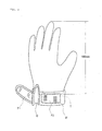
- a hem of the glove obtained in Example 1 was laterally cut at a position about 190 cm from a tip of a middle finger (position indicated by T in Fig. 4 ).
- a knitted rubber (40 mm in width) W was sewed with threads (manufactured by FUJIX Ltd., polyester spun thread No. 60 yarn number count) using a zigzag stitch sewing machine (manufactured by Brother Industries, Ltd., model LZ2-B856E-301).
- a slit C of about 40 mm in length was vertically cut in a side on a little finger side.
- a face fastener (hook-like male: 30 ⁇ 60 mm, loop(pile)-like female: 30 ⁇ 50 mm) was prepared.
- the male portion F1 of the face fastener was bordered with a bias tape (15 mm ⁇ 120 mm) in advance.
- the bias tape was sewed by a sewing machine (MITSUBISHI LY2-3300 manufactured by Mitsubishi Electric Corp.) using threads (manufactured by COATS PLC, 45 tex, Nylon Thread Yarn Wine 916PQ).
- the rubber coating layer is formed on the glove made of fibers (knitted gloves), there is no straggling of the glove made of fibers in cutting the glove, and therefore the step of preventing straggling is unnecessary and workability is extremely good.
- a coating layer composed of rubber containing air bubbles is formed at least on a back portion of a glove, it is possible to provide a glove which has good moisture permeability and abrasion resistance of the back portion, does not cause heat trapped and a steamy condition in the glove to provide an excellent feel upon wearing, can protect the back portion from breakages due to rubbing or scratching and protect from perforations or damages due to sparks generated in a metal cutting work and is superior in protection performance.
Landscapes
- Engineering & Computer Science (AREA)
- Textile Engineering (AREA)
- Gloves (AREA)
Abstract
Description
- The present invention relates to a glove having excellent moisture permeability and abrasion resistance of a back portion, and more specifically, to a glove which, by forming a coating layer having excellent moisture permeability and abrasion resistance on a back portion which tends to be damaged due to rubbing or scratching, does not bring about heat trapped and a steamy condition in a glove to provide an excellent feel when wearing and can further protect the back portion from breakages due to rubbing or scratching or from perforations or damages due to sparks generated in a metal cutting work, and a method of producing the same.
- Hitherto, as the gloves of this kind, a glove in which a coating layer is provided by sticking or sewing a synthetic leather to a palm portion of a glove made of fibers , and a glove, in which a palm portion is covered with resin or rubber and a back portion is not provided with these coating layers to secure air permeability of a base material made of fibers, are used.
- For example, in a glove for sporting in which a palm portion is composed of a natural leather or a synthetic leather and the whole back of the hand including finger bags is composed of a fabric, a glove for sporting, in which the whole back of the hand including finger bags in a glove main body is configured so as to be a two-layered structure in which a chemical fiber fabric is disposed on an inner side and a cotton fabric is disposed on an outer side, is proposed (for example,
JP-A-11-290497 - Further, a slip resistant glove in which a foam layer composed of a thermoplastic resin or rubber is formed on the glove base material made of fibers and the surface of the foam layer has a projection and depression shape, in which the foam layer is mechanically foamed and hot pressed in a semi-crosslinked or gelled state to be provided with projections and depressions on the surface, and a depression portion of the foam layer is compressed in such a way that an air bubble content is 10 to 90% by volume with respect to that of a projection portion, and many openings being the impressions of air bubbles are formed at the surface of the projection portion, is proposed (for example, Japanese Patent Publication No.
4242338 - Furthermore, a working glove is proposed which is characterized in that a slip resistant coating is formed by coating the surface of a glove main body formed by sewing leather as a material with a synthetic rubber and the synthetic rubber is a copolymer of butadiene and styrene or a copolymer of butadiene and acrylonitrile, which is excellent in oil resistance, acid resistance and alkali resistance (for example,
JP-A-7-278923 - However, since the whole back portion of the glove described in
JP-A-11-290497 - Further, the glove described in Japanese Patent Publication No.
4242338 JP-A-11-290497 - In the glove described in
JP-A-7-278923 - In view of the above state of the art, it is an object of the present invention to provide a glove which solves the above-mentioned problems of conventional techniques, has excellent moisture permeability and an excellent feel upon wearing, and has excellent abrasion resistance of a back portion.
- The present invention was made in order to solve the above-mentioned problems, and is characterized by the following items.
- (1) A glove provided with a coating layer of rubber containing air bubbles formed at least on the surface of a back portion of a glove base material made of fibers, wherein the moisture permeability of the coating layer of the back portion ranges from 1000 to 9000 g/m2·24 hrs in terms of a measured value according to JIS L 1099 A-1 method (calcium chloride method) and the wear loss of the coating layer of the back portion is 40 mg or less in terms of a value measured after 100 revolutions by use of a tester, Nu-Martindale Abrasion and Pilling Tester, specified by EN ISO 12947-1, according to the European Standard EN 388; 2003.
- (2) The glove according to (1), wherein the average air bubble content of the coating layer is 12 to 85%.
- (3) The glove according to (1), wherein the wear losses of the nail portions of the coating layer and of the first joint portions, the second joint portions and the third joint portions of fingers of the coating layer are respectively 7 mg or less in terms of values measured after 100 revolutions by use of a tester, Nu-Martindale Abrasion and Pilling Tester, specified by EN ISO 12947-1, according to the European Standard EN 388; 2003.
- (4) The glove according to (3), wherein the average air bubble contents of the nail portions, the first joint portions, the second joint portions and the third joint portions of the coating layer are respectively 0 to 10%.
- (5) The glove according to any one of (1) to (4), wherein a face fastener is provided to a hem portion of a rubber coating layer of the glove.
- (6) A method for producing a glove, which comprises the steps of; forming a coating layer having an average air bubble content of 22 to 89% at least on the surface of a back portion of a glove base material made of fibers by use of a rubber blended solution having the average air bubble content of 7 to 88% by volume, and
hot pressing the coating layer in such a way that the average air bubble content of the coating layer is 12 to 85%. - (7) The method for producing a glove according to (6), wherein a water content of the coating layer having the average air bubble content of 22 to 89% is adjusted to 20 to 170% by weight and then the coating layer is hot pressed.
- (8) The method for producing a glove according to (6) or (7),
wherein the coating layer is hot pressed by use of a pressing plate having a projection and depression pattern. - (9) The method for producing a glove according to (6) or (7),
wherein the coating layer is hot pressed by use of a pressing plate not having a projection and depression pattern. - (10) The method of producing a glove according to any one of (6) to (9), wherein a face fastener is attached to a hem portion of a rubber coating layer.
- Since the glove of the present invention is provided with a coating layer which is composed of rubber containing air bubbles and formed at least on a back portion, it has good moisture permeability and abrasion resistance of a back portion, does not cause a trapping of heat and a steamy condition in the glove to provide an excellent feel upon wearing, hardly cause breakages due to rubbing or scratching and is hardly perforated, for example, due to sparks generated in a metal cutting work and is superior in protection performance.
- The invention is described in detail in connection with the drawings in which
-
Fig. 1 is a view showing measurement points of the average air bubble content of a coating layer; -
Fig. 2(a) is a photograph showing a pressing plate used in Examples, which has an infinite projection and depression pattern, andFig. 2(b) is a magnified photograph (200 times magnification) of the pressing plate; -
Fig. 3 is a schematic view showing a jig for fastening a test piece in measuring a wear loss by use of a tester, Nu-Martindale; and -
Fig. 4 is a schematic view showing a glove on the hem of which a face fastener is sewed. - The glove of the present invention is characterized in that a coating layer of rubber containing air bubbles is formed at least on the surface of a back portion of a glove base material made of fibers, the moisture permeability of the coating layer of the back portion ranges from 1000 to 9000 g/m2·24 hrs in terms of a measured value according to JIS L 1099 A-1 method (calcium chloride method), and the wear loss of the coating layer of the back portion is 40 mg or less in terms of a value measured after 100 revolutions by use of a tester, Nu-Martindale Abrasion and Pilling Tester, specified by EN ISO 12947-1, according to the European Standard EN 388; 2003.
- The glove of the present invention requires that the moisture permeability of the coating layer of the back portion ranges from 1000 to 9000 g/m2·24 hrs in terms of a measured value according to JIS L 1099 A-1 method (calcium chloride method). When the moisture permeability is less than 1000 g/m2·24 hrs, the moisture permeability of the coating layer is insufficient and the problems of heat trapped and a steamy condition in a glove are not adequately solved. On the other hand, when the moisture permeability is more than 9000 g/m2·24 hrs, the abrasion resistance of the coating layer is insufficient.
- Further, the glove of the present invention requires that the wear loss of the coating layer of the back portion is 40 mg or less in terms of a value measured after 100 revolutions by use of a tester, Nu-Martindale Abrasion and Pilling Tester, specified by EN ISO 12947-1, according to the European Standard EN 388; 2003. When the wear loss is more than 40 mg, the abrasion resistance of the coating layer is insufficient and breakage of the coating layer due to rubbing or scratching cannot be adequately prevented.
- In order to achieve the above-mentioned moisture permeability and abrasion resistance of the coating layer, it is preferable that the average air bubble content of the coating layer is 12 to 85%. When the average air bubble content of the coating layer is less than the above range, moisture permeability tends to be insufficient, and on the other hand, when the average air bubble content is more than the above range, abrasion resistance tends to be insufficient.
- It is preferred that, of the coating layer of the back portion, particularly, nail portions, the first joint portions, the second joint portions and the third joint portions of fingers, which easily undergo breakages due to rubbing or scratching, have a wear loss of 7 mg or less. By keeping the wear losses of these portions below 7 mg, these portions hardly undergo breakage even when these portions are brought into contact with metal portions, etc., rubbed or scratched during works, and can further prevent the trouble that these portions are perforated due to sparks generated in metal cutting works. Therefore, gloves having even more excellent protection performance can be attained.
- The average air bubble contents of the coating layers of these portions are preferably 0 to 10%.
- It is preferred that the glove base material made of fibers used in the present invention is made by use of natural fibers or chemical fibers, such as cotton, wool, polyester, polyamide (nylon), acryl, aramide, reinforced polyethylene or the like. A stretching rate per a unit area of the glove base material made of fibers is usually about 150 to 650%. The stretching rate is the maximum enlarging rate when simultaneously stretching the base material longitudinally and laterally. If the stretching rate of the glove base material made of fibers is small, wrinkles, particularly, deep wrinkles in a palm and a thumb, occur in a product prepared after the glove base material made of fibers is released from a hand mold for immersion and put on a hand mold for setting used in hot pressing, and cured vulcanized). Further cracks often occur on a coating layer. Moreover, a knitted or sewed glove base material containing polyurethane elastic fibers in which the stretching rate is imparted to fibers is also used. The glove base material made of fibers is dyed or purified as required.
- Examples of the rubber used in the present invention include natural rubber, homopolymers or copolymers such as isoprene, chloroprene, acrylic ester rubber, styrene-butadiene copolymers, acrylonitrile-butadiene copolymers, polyurethane, butyl rubber, polybutadiene rubber and silicone rubber, copolymers containing 10% by weight or less of a carboxyl-modified group, and those blended with the copolymers. The term natural rubber includes not only natural rubber alone, but also a natural rubber-methylmethacrylate copolymer, epoxy-modified natural rubber copolymer, and the like. The term acrylic ester rubber includes homopolymers or copolymers such as n-butyl acrylate, n-butyl methacrylate, iso-butyl acrylate, iso-butyl methacrylate, ethyl acrylate, 2-ethylhexyl acrylate, 2-ethylhexyl methacrylate, iso-propyl acrylate and iso-propyl methacrylate, which contain acrylonitrile, methyl methacrylate, allyl methacrylate, N-methylol acrylamide, acrylic acid, methacrylic acid, or the like.
- Generally, a crosslinking agent, a vulcanization accelerator, an antioxidant, a thickener or the like, and a foaming agent or a foam stabilizer can be added to the rubber.
- Examples of the foaming agent include sodium sulfosuccinate based surfactants, alkylmonoamide disodium sulfosuccinate, potassium oleate, castor oil potassium, sodium dodecylbenzenesulfonate, and the like, and these can be used singly or in combination of two or more.
- Examples of the foam stabilizer include ammoniumstearate, peptide, sodium alkyldipropionate, and the like, and these can be used singly or in combination of two or more. Alkyl includes lauryl, octyl, stearyl, and the like.
- Further, as an air bubble stabilizer for a coating layer, if 15 to 50 parts by weight of 2,2,4-trimethyl-1,3-pentanediolmonoisobutylate is added to 100 parts by weight of rubber, processability is improved which is preferable.
- To the above rubber, known chemical foaming agents, such as toluenesulfonyl hydrazide, pp'oxybis(benzosulfonyl hydrazide), azodicarbonamide and azobisisobutylonitrile, or microcapsules may be further added to reduce the number of open holes for the purpose of preventing absorption of oils or chemicals to the surface of the coating layer. Moreover, particles of acryl, urethane, natural rubber powder, EVA powder, PVC, or NBR may be further added in order to increase a solid content to enhance abrasion resistance.
- The glove of the present invention can be prepared by forming a rubber coating layer including air bubbles at least on a back portion of a glove base material made of fibers by use of a rubber blended solution including air bubbles, then hot pressing the coating layer.
- A preferable production method will be described. First, a glove base material made of fibers is put on a hand mold for immersion. As the hand mold for immersion, a ceramic hand mold, an aluminum alloy hand mold or the like are suitably used, and a hand mold having a configuration in which fingers from a thumb to a little finger are arranged linearly is preferable. The glove base material made of fibers is put on the hand mold for immersion preheated to 50 to 70°C, and immersed in, for example, methanol containing calcium nitrate or a warm water bath of a coagulant solution, adjusted to 50 to 70°C, which contains calcium nitrate. The content of the coagulant is preferably adjusted in such a way that a rubber blended solution partially penetrates into the glove base material made of fibers in order to avoid the deterioration of touch feeling.
- The immersed hand mold with the glove base material made of fibers put thereon, which has been immersed in the warm water bath of a coagulant solution, is immersed in a bath of a rubber blended solution including air bubbles. In immersion, generally, a method of immersing a glove vertically from a fingertip to a wrist is adopted.
- The blended solution is mechanically foamed with a bubbling machine or a mixer. The average air bubble content of the blended solution is preferably adjusted to 7 to 88% by volume, more preferably 9 to 61% by volume. Thereby, gloves having excellent moisture permeability and abrasion resistance, in which the desired moisture permeability of a coating layer is 1000 to 9000 g/m2·24 hrs and the desired wear loss of a coating layer is 40 mg or less, are obtained.
- The average air bubble content (% by volume) of the blended solution is determined by the following method.
- When A ml of a blended solution without including air bubbles is stirred with a bubbling machine or a mixer to include air to obtain B ml of a blended solution including air bubbles, the average air bubble content is calculated from the following equation;

- Further, the average air bubble diameter of the blended solution is preferably 10 to 200 µm, more preferably 10 to 100 µm. The average air bubble diameter of 10 to 200 µm increases when a coating layer is formed and hot pressed, and therefore, the average air bubble diameter of the coating layer becomes approximately 30 to 400 µm. The average air bubble diameter of the coating layer is important for design, and when the average air bubble diameter is more than 400 µm, the design tends to be impaired. Accordingly, an upper limit of the average air bubble diameter of the blended solution is preferably approximately 200 µm. On the other hand, when the average air bubble diameter of the blended solution is less than 10 µm, adjustment is difficult even if mechanical shear is exerted. The blended solution having the average air bubble diameter of 10 to 200 µm can be obtained by exerting shear on the blended solution with a high-speed mixer of about 600 to 1200 rpm or a bubbling machine.
- The average air bubble diameter (µm) of the blended solution is measured by the following method.
- 10 g of a blended solution is put in a petri dish, and observed with a microscope VHX-900 (manufactured by KEYENCE Corp.). In images taken at 200 times magnification, ten diameters of five air bubbles selected in decreasing order of bubble diameter from the largest bubble diameter and five air bubbles selected in increasing order of bubble diameter from the smallest bubble diameter are measured in an image of 2000 µm × 2000 µm, and an average of the ten diameters is calculated.
- The glove immersed in the bath of a rubber blended solution including air bubbles is pulled out from the blended solution, and then is dried at 60 to 95°C by heating to be semi-cured (semi-gelled). The average air bubble content of the semi-cured coating layer is 22 to 89%, preferably 26 to 64%. This average air bubble content can be adjusted by the concentration of solid matter in the the blended solution and the viscosity of the blended solution, or a foam stabilizer. Thereafter, generally, the glove is leached by water washing and hot pressed. By hot pressing, a part of the air bubbles in the coating layer is crushed and the air bubbles can be made to communicate with one another to increase the moisture permeability. Moreover, walls forming air bubbles are melted to one another to decrease the air bubble content to increase the abrasion resistance. The coating layer can be preferably hot pressed by adjusting the water content of the coating layer before hot pressing to 20 to 170% by weight. Particularly when the coating layer is provided with a projection and depression pattern through hot pressing, the projection and depression pattern can be beautifully formed.
- The water content (% by weight) in the coating layer before hot pressing is calculated from the following equation.

- When the projection and depression pattern is formed, a pressing plate having a projection and depression pattern (hereinafter, referred to as a projection and depression plate) is used.
- When the projection and depression pattern is formed on only the back side, the projection and depression plate is used for the pressing plate on the back side and a pressing plate without a projection and depression pattern (hereinafter, referred to as a projection plate) is used for the pressing plate on the palm side. Further, when the projection and depression pattern is used on both of the back side and the palm side, the projection and depression plate is used for both of the back side and the palm side.
- As another method, the glove in which a coating layer is formed is removed from the hand mold for immersion, put on a flat mold again, and hot pressed as with the above method. Further, when hot pressing is carried out from both of the back side and the palm side of the glove, pressing can be performed at a uniform pressure by using a female mold composed of a projection and depression plate or a projection plate prepared in conformity with the configuration of the hand mold for immersion. In this case, hot pressing can be applied up to a side of the glove, and when the female mold composed of a projection and depression plate is used, a projection and depression pattern is beautifully formed up to a side of the glove.
- The depth of projection and depression (difference in level between the projection and the depression) of the projection and depression plate is preferably in a range from about 0.1 mm to about 1.2 mm, and more preferably about 0.3 mm to about 1.0 mm from the viewpoint of a grip force and design. The depth of the projection plate without having a projection and depression pattern is the same as above. By adjusting the depth of projection and depression of the projection and depression plate or the depth of the projection plate within the above range, abrasion resistance and moisture permeability can be adjusted to a desired range. A shape of the projection and depression pattern of the projection and depression plate is not particularly limited, and examples of the shape include a variety of geometric patterns such as a circle, a shape of an ellipse, a rectangle, a polygonal shape, and the like, and infinite patterns (See
Fig. 2 ), and when these are arranged regularly or irregularly, not only abrasion resistance is improved, but also a grip force is improved and design is enhanced. - The coating layer is hot pressed so that its average air bubble content is 12 to 85%, preferably 15 to 60%. When the average air bubble content is less than 12%, moisture permeability may be insufficient, and when the average air bubble content is more than 85%, abrasion resistance may be insufficient, and therefore it becomes difficult to obtain a coating layer in which the desired moisture permeability is 1000 to 9000 g/m2·24 hrs and the desired wear loss is 40 mg or less.
- For decreasing the average air bubble content of the coating layer, methods in which the depth of the projection and depression plate or the projection plate is increased, and an area of a projection portion is increased, and when the projection and depression plate is used, methods in which a time of hot pressing is increased, or hot pressing is repeated twice or more are employed, and for increasing the average air bubble content of the coating layer, methods contrary to the above methods are employed.
- The average air bubble content (%) of the coating layer before or after pressing is determined by the following method.
- As shown in
Fig. 1 , a point of intersection of a line α, which extends from a finger crotch between a thumb and an index finger and is parallel to a line β connecting a finger crotch between an index finger and a middle finger to a finger crotch between a third finger and a little finger, and a line γ connecting a middle finger tip and a center of a wrist is taken as a point a, and apoint 1 cm upward and apoint 1 cm downward from the point a on the line γ are taken as b and c, respectively, and apoint 1 cm left and apoint 1 cm right from the point a on the line α are taken as d and e, respectively. Images of cross-sections of the coating layer, indicated by lines b-c and d-e, which are taken at 200 times magnification by a microscope VHX-900 (manufactured by KEYENCE Corp.), are obtained, and an average ratio of areas of air bubbles in a division of 300 µm × 300 µm of each the images is calculated from the following equation.
- Particularly the nail portions and the first joint portions, the second joint portions and the third joint portions of fingers, which easily suffer from wear or abrasion of the back portion, are preferably pressed as required in such a way that the average air bubble content of the coating layer is 0 to 10%. Thereby, a glove, in which a wear loss is 7 mg or less and abrasion resistance is locally improved, is obtained. The glove in which abrasion resistance is improved as described above further hardly undergoes breakage due to rubbing or scratching during a work, and further hardly suffers from the trouble that the back portions of the glove is perforated even in a work where sparks fly about,such as in a metal cutting work. Therefore, a glove having excellent protection performance can be provided.
- In addition, when the average air bubble content of the coating layer is 0 to 10% locally, the moisture permeability is reduced to about 100 to 500 g/m2·24 hrs at such portions, but since the moisture permeability of other portions is 1000 to 9000 g/m2·24 hrs, the moisture permeability of the whole back portion is sufficient and this does not bring about a problem practically.
- In order to keep the average air bubble contents of the nail portions of the coating layer, and the first joint portions, the second joint portions and the third joint portions of fingers of the coating layer in a range of 0 to 10%, a method in which a depth of a projection and depression plate or a projection plate for these portions is made larger than that of other portions or areas of projections for the projection and depression plate are increased, is preferable because hot pressing only has to be carried out once. However, by carrying out the hot pressing twice or more, the average air bubble contents of these portions can also be adjusted.
- The average air bubble contents of the nail portions of the coating layer, and the first joint portions, the second joint portions and the third joint portions of fingers of the coating layer are calculated by the following method.
- As shown in
Fig. 1 , images of cross-sections of the coating layers of a nail portion A of a middle finger, a first joint B of a thumb, a second joint C1 of a middle finger, a second joint C2 of a little finger and a third joint D of a middle finger, which are taken at 200 times magnification by a microscope VHX-900 (manufactured by KEYENCE Corp.), are obtained, and an average ratio (%) of areas of air bubbles in a division of 300 µm × 300 µm of each of images is calculated from the following equation.
- In addition, since the nail portions and the joint portions vary with a glove size and a hand size of wearer, it is preferred that the gloves are previously adjusted according to a small size (S), a middle size (M), a large size (L) or an oversize (LL), or a little broader area is hot pressed so that the coating layer can be applied regardless of whether a size is large or small.
- The glove is released from the hand mold, and then put on a hand mold for setting having a configuration close to a human hand, in which a thumb is located on an inner side, cured at 120 to 130°C for 40 to 60 minutes and released from the hand mold.
- A hem portion (wrist portion) of the released glove is cut as required for preventing slippage, for example, and a part such as a face fastener (hook-and-loop fastener) is sewed to be finished.
- Hereinafter, the present invention will be described in more detail by way of examples and comparative examples, but the present invention is not limited to these examples and comparative examples.
- The average air bubble content of a blended solution, the water content of a coating layer, the average air bubble content of the coating layer, and the moisture permeability and the wear loss of the coating layer were measured by the methods described above.
- The wear loss was measured by a method of using a tester, Nu-Martindale, described above, and in the present invention, a jig shown in
Fig. 3 was used as a jig for fastening a test piece in order to measure the wear losses of nail portions or local portions in joint portions. A unit of numbers inFig. 3 is a millimeter. - Further, the steamy feel was evaluated based on the presence or absence of a steamy feel in actually wearing the gloves. The perforation was evaluated by placing the glove so as to be hit by sparks generated in cutting an equal-angle steel and observing the surface of a coating layer of the glove with the naked eye after cutting the steel.
-
NBR latex (manufactured by ZEON Corp., Lx550) 100 parts by weight Colloidal sulfur (manufactured by Hosoi Chemical Industry Co., Ltd.) 2.0 parts by weight Zinc oxide (No.2 Chinese white, manufactured by Seido Chemical Industry Co., Ltd) 1.0 part by weight Vulcanization accelerator (zinc dibutyldithiocarbamate, manufactured by OUCHI SHINKO CHEMICAL INDUSTRIAL Co., Ltd.) 0.5 parts by weight Antioxidant (2,2'-methylenebis(4-ethyl-6-tert-butylphenol)) (manufactured by Bayer Holding Ltd., BKF) 0.5 parts by weight Pigment (manufactured by MIKUNI COLOR Ltd., SABlue 12402) 0.3 parts by weight Thickener (polyacrylic ester) (manufactured by TOAGOSEI Co., Ltd., A-7075) 0.2 parts by weight Foaming agent (sodium sulfosuccinate) (manufactured by Kao Corp., PELEX TA) 3.0 parts by weight Foam stabilizer (sodium lauryldipropionate) (manufactured by Takemoto Oil & Fat Co., Ltd., PIONIN C-158-D) 3.0 parts by weight Water (adjusted in such a way that solid content is 38 % by weight) - The above-mentioned rubber blended solution was stirred so as to include air by an automatic handheld mixer for home use to prepare a blended solution in which an average air bubble content is 33 % by volume (average
air bubble diameter 30 µm). - A knitted glove (280 d) made of wooly nylon was put on a hand mold for immersion, in which fingers from a thumb to a little finger are arranged linearly, and immersed in a 0.7 weight % methanol coagulating solution of calcium nitrate, and then the glove was immersed vertically in the blended solution including air bubbles from a fingertip to a wrist, and thereafter, the glove was dried at 75°C for 10 minutes to be semi-cured (semi-gelled) and released from the hand mold. The average thickness of the coating layer was 0.7 mm. The released glove was leached by water washing, and the water content of the coating layer was adjusted to 50% by weight, and then the glove was put on the flat mold again and hot pressed.
- As a hot pressing plate, a projection and depression plate having an infinite projection and depression pattern (depth is 0.7 mm and a ratio of a projection area to a depression area per 1 cm2 is 8/3) shown in
Figs. 2(a) and 2(b) (cross-cut inFig. 2(b) represents a dimension and one side of a cross-cut indicates 1 mm) on a back side and a palm side of the glove was used, and the glove was hot pressed at a pressure of 1 kgf/cm2 at 180°C for 5 seconds. - The hot pressed glove was put on a hand mold for setting (a hand mold close to a human hand, in which a thumb is located at a position shifted to a palm side) again, cured at 120°C for 60 minutes and released from the hand mold to obtain a glove in which a coating layer including air bubbles was formed on both sides of a palm portion and a back portion.
- A summary of production conditions and the results of evaluation of properties are shown in Table 1.
- A glove in which a coating layer including air bubbles was formed on both sides of a palm portion and a back portion, was prepared in the same manner as in Example 1 except for changing the average air bubble content of the blended solution from 33% by volume to 88% by volume.
- A summary of production conditions and the results of evaluation of properties are shown in Table 1.
- A glove was prepared in the same manner as in Example 1 except for changing the hot pressing plate from the projection and depression plate having a projection and depression pattern to a projection plate (depth is 0.7 mm) without having a projection and depression pattern.
- A summary of production conditions and the results of evaluation of properties are shown in Table 1.
- A glove was prepared in the same manner as in Example 2 except for changing the hot pressing plate from the projection and depression plate having a projection and depression pattern to a projection plate (depth is 0.7 mm) without having a projection and depression pattern.
- A summary of production conditions and the results of evaluation of properties are shown in Table 1.
- A glove was dried, leached, hot pressed with a projection and depression plate, and cured in the same manner as in Example 1 except that only the palm portion of the knitted glove made of wooly nylon was immersed in the blended solution to prepare a glove in which a coating layer including air bubbles was formed on only a palm portion.
- A summary of production conditions and the results of evaluation of properties are shown in Table 1.
- A glove, in which a coating layer including air bubbles is formed on both sides of a palm portion and a back portion, was prepared in the same manner as in Example 1 except for changing the average air bubble content of the blended solution from 33% by volume to 3.5% by volume.
- A summary of production conditions and the results of evaluation of properties are shown in Table 1.
- A glove, in which a coating layer including air bubbles was formed on both sides of a palm portion and a back portion, was prepared in the same manner as in Example 1 except for changing the average air bubble content of the blended solution from 33% by volume to 103% by volume.
- A summary of production conditions and the results of evaluation of properties are shown in Table 1.
- A glove, in which a coating layer including air bubbles was formed on both sides of a palm portion and a back portion, was prepared in the same manner as in Example 1 except for changing the average air bubble content of the blended solution from 33% by volume to 3.5% by volume and changing the hot pressing plate from the indefinite projection and depression plate to a projection plate.
- A summary of production conditions and the results of evaluation of properties are shown in Table 1.
- A glove, in which a coating layer including air bubbles was formed on both sides of a palm portion and a back portion, was prepared in the same manner as in Example 1 except for changing the average air bubble content of the blended solution from 33% by volume to 103% by volume and changing the hot pressing plate from the indefinite projection and depression plate to a projection plate.
- A summary of production conditions and the results of evaluation of properties are shown in Table 1.
- The glove obtained in Example 1, in which a coating layer including air bubbles was formed on both sides of a palm portion and a back portion, was put on a flat mold, and nail portions, and the first joint portions, the second joint portions and the third joint portions of the coating layer of a back portion were locally hot pressed again with a projection plate (depth is 0.7 mm).
- A summary of production conditions and the results of evaluation of properties are shown in Table 2.
- The glove obtained in Example 2, in which a coating layer including air bubbles was formed on both sides of a palm portion and a back portion, was put on a flat pattern, and nail portions, and the first joint portions, the second joint portions and the third joint portions of the coating layer of a back portion were locally hot pressed again with a projection plate (depth is 0.7 mm).
- A summary of production conditions and the results of evaluation of properties are shown in Table 2.
- It is apparent from the results shown in Table 1 that the gloves of the present invention represented by the gloves in Examples 1 to 4 cause no steamy feel because of excellent moisture permeability of a back portion, and are not perforated due to sparks generated in a metal cutting work because of excellent abrasion resistance and are superior in protection performance.
- Further, it is apparent from the results shown in Table 2 that by locally hot pressing nail portions, and the first joint portions, the second joint portions and the third joint portions of a back portion of the gloves of the present invention, the abrasion resistance of these portions is further enhanced, and gloves having a further excellent protection performance are obtained even under severe working conditions.
Table 1 Rubber blended solution Back side of hot pressing plate Air bubble content of coating layer of back portion Properties back portion Kind Air bubble content (%) Before hot pressing After hot pressing Moisture permeability g/m2 · 24hrs Steamy feel Wear (mg) loss Perforation Example 1 NBR 33 Infinite projection and depression plate 35 18 1094 Absence 6. 5 Absence Example 2 NBR 88 Infinite projection and depression plate 89 76 8090 Absence 22 Absence Example 3 NBR 33 Projection plate 35 19 2141 Absence 8. 5 Absence Example 4 NBR 88 Projection plate 89 50 7452 Absence 17.7 Absence Comp. Example 1 NBR 33 - - - 13449 Absence Broken Presence Comp. Example 2 NBR 3.5 Infinite projection and depression plate 15 11 570 Presence 5. 9 Absence Comp. Example 3 NBR 103 Infinite projection and depression plate 99 94 9600 Absence 42.6 Absence Comp. Example 4 NBR 3. 5 Projection plate 14 10 566 Presence 5.4 Absence Comp. Example 5 NBR 103 Projection plate 98 93 9570 Absence 41. 7 Absence Table 2 Back side of hot pressing plate Air bubble content of coating layer of back portion after hot pressing Properties of nail portion and joint portions Portions other than nail portion and joint portions Nail portion, joint portions Portions other than nail portion and joint portions Nail portion, joint portions Steamy feel Wear loss (mg) Perforation Example 5 Infinite projection and depression plate Projection plate 18 5 Absence 2. 1 Absence Example 6 Infinite projection and depression plate Projection plate 76 8 Absence 4.9 Absence - A hem of the glove obtained in Example 1 was laterally cut at a position about 190 cm from a tip of a middle finger (position indicated by T in
Fig. 4 ). - Next, on the cut hem portion, a knitted rubber (40 mm in width) W was sewed with threads (manufactured by FUJIX Ltd., polyester spun thread No. 60 yarn number count) using a zigzag stitch sewing machine (manufactured by Brother Industries, Ltd., model LZ2-B856E-301).
- Next, a slit C of about 40 mm in length was vertically cut in a side on a little finger side. Then, a face fastener (hook-like male: 30 × 60 mm, loop(pile)-like female: 30 × 50 mm) was prepared. The male portion F1 of the face fastener was bordered with a bias tape (15 mm × 120 mm) in advance. In bordering, the bias tape was sewed by a sewing machine (MITSUBISHI LY2-3300 manufactured by Mitsubishi Electric Corp.) using threads (manufactured by COATS PLC, 45 tex, Nylon Thread Yarn Wine 916PQ). This bordered male portion F1 of the face fastener was sewed on a side closer to a little finger of the above slit C by straight stitch, and the female portion F2 of the face fastener was sewed similarly on a portion of the knitted rubber W corresponding to the male portion F1 of the face fastener. Finally, the edge of the slit C was bordered with a bias tape to obtain a glove preventing slippage.
- Since the rubber coating layer is formed on the glove made of fibers (knitted gloves), there is no straggling of the glove made of fibers in cutting the glove, and therefore the step of preventing straggling is unnecessary and workability is extremely good.
- In addition, it is needless to say that there is no problem if the male portion F1 and the female portion F2 of the face fastener change places in the present example.
- In accordance with the present invention, since a coating layer composed of rubber containing air bubbles is formed at least on a back portion of a glove, it is possible to provide a glove which has good moisture permeability and abrasion resistance of the back portion, does not cause heat trapped and a steamy condition in the glove to provide an excellent feel upon wearing, can protect the back portion from breakages due to rubbing or scratching and protect from perforations or damages due to sparks generated in a metal cutting work and is superior in protection performance.
Claims (10)
- A glove provided with a coating layer of rubber containing air bubbles formed at least on the surface of a back portion of a glove base material made of fibers, wherein the moisture permeability of the coating layer of the back portion ranges from 1000 to 9000 g/m2·24 hrs in terms of a measured value according to JIS L 1099 A-1 method (calcium chloride method) and the wear loss of the coating layer of the back portion is 40 mg or less in terms of a value measured after 100 revolutions by use of a tester, Nu-Martindale Abrasion and Pilling Tester, specified by EN ISO 12947-1, according to the European Standard EN 388; 2003.
- The glove according to claim 1, wherein the average air bubble content of the coating layer is 12 to 85%.
- The glove according to claim 1 or 2, wherein the wear losses of nail portions, first joint portions, the second joint portions and the third joint portions of the coating layer are respectively 7 mg or less in terms of values measured after 100 revolutions by use of a tester, Nu-Martindale Abrasion and Pilling Tester, specified by EN ISO 12947-1, according to the European Standard EN 388; 2003.
- The glove according to claim 3, wherein the average air bubble contents of the nail portions, the first joint portions, the second joint portions and the third joint portions of the coating layers are respectively 0 to 10%.
- The glove according to any one of claims 1 to 4, wherein a face fastener is provided to a hem portion of a rubber coating layer of the glove.
- A method for producing a glove, which comprises the steps of; forming a coating layer having the average air bubble content of 22 to 89% at least on the surface of a back portion of a glove base material made of fibers by use of a rubber blended solution having the average air bubble content of 7 to 88% by volume, and
hot pressing the coating layer in such a way that the average air bubble content of the coating layer is 12 to 85%. - The method for producing a glove according to claim 6, wherein a water content of the coating layer having the average air bubble content of 22 to 89% is adjusted to 20 to 170% by weight and then the coating layer is hot pressed.
- The method for producing a glove according to claim 6 or 7,
wherein the coating layer is hot pressed by use of a pressing plate having a projection and depression pattern. - The method for producing a glove according to claim 6 or 7,
wherein the coating layer is hot pressed by use of a pressing plate not having a projection and depression pattern. - The method for producing a glove according to any one of claims 6 to 9, wherein a face fastener is attached to a hem portion of a rubber coating layer of the glove.
Applications Claiming Priority (2)
| Application Number | Priority Date | Filing Date | Title |
|---|---|---|---|
| JP2010152493 | 2010-07-02 | ||
| JP2011116610A JP5964556B2 (en) | 2010-07-02 | 2011-05-25 | Gloves and manufacturing method thereof |
Publications (3)
| Publication Number | Publication Date |
|---|---|
| EP2401931A2 true EP2401931A2 (en) | 2012-01-04 |
| EP2401931A3 EP2401931A3 (en) | 2013-03-13 |
| EP2401931B1 EP2401931B1 (en) | 2014-08-06 |
Family
ID=44533825
Family Applications (1)
| Application Number | Title | Priority Date | Filing Date |
|---|---|---|---|
| EP11172164.3A Active EP2401931B1 (en) | 2010-07-02 | 2011-06-30 | Glove and method for producing the same |
Country Status (3)
| Country | Link |
|---|---|
| US (1) | US8689363B2 (en) |
| EP (1) | EP2401931B1 (en) |
| JP (1) | JP5964556B2 (en) |
Cited By (1)
| Publication number | Priority date | Publication date | Assignee | Title |
|---|---|---|---|---|
| US20150000349A1 (en) * | 2012-03-01 | 2015-01-01 | Showa Glove Co. | Method for manufacturing glove, method for manufacturing coated glove, glove, and coated glove |
Families Citing this family (4)
| Publication number | Priority date | Publication date | Assignee | Title |
|---|---|---|---|---|
| JP5951281B2 (en) | 2012-02-28 | 2016-07-13 | ショーワグローブ株式会社 | Gloves and manufacturing method thereof |
| US9730477B2 (en) | 2013-12-13 | 2017-08-15 | Covco Ltd. | Ambidextrous fish scale-textured glove |
| US11241051B2 (en) * | 2014-07-08 | 2022-02-08 | Covco (H.K.) Limited | Ambidextrous fish scale-textured glove |
| US11071343B2 (en) * | 2017-08-07 | 2021-07-27 | Capps Llc | Cap with interchangeable art |
Citations (3)
| Publication number | Priority date | Publication date | Assignee | Title |
|---|---|---|---|---|
| JPH07278923A (en) | 1994-04-01 | 1995-10-24 | Hirohisa Kida | Working glove made of leather |
| JPH11290497A (en) | 1998-04-15 | 1999-10-26 | Yokohama Rubber Co Ltd:The | Glove for sports |
| JP4242338B2 (en) | 2004-12-17 | 2009-03-25 | ショーワグローブ株式会社 | Non-slip gloves |
Family Cites Families (12)
| Publication number | Priority date | Publication date | Assignee | Title |
|---|---|---|---|---|
| US2393298A (en) * | 1938-04-15 | 1946-01-22 | Seamless Rubber Co | Rubber glove and like article |
| US4329312A (en) * | 1969-11-14 | 1982-05-11 | Affiliated Hospital Products, Inc. | Method of making gloves |
| JPS5891801A (en) * | 1981-11-24 | 1983-05-31 | 東和グロ−ブ株式会社 | Glove and production thereof |
| US4514460A (en) * | 1982-10-25 | 1985-04-30 | Becton, Dickinson And Company | Slip resistant surfaces |
| US4567612A (en) * | 1982-10-25 | 1986-02-04 | Becton, Dickinson And Company | Slip resistant gloves |
| CA2529392C (en) * | 2003-07-02 | 2012-10-16 | Ansell Healthcare Products Llc | Textured surface coating for gloves and method of making |
| US7487553B2 (en) * | 2004-01-26 | 2009-02-10 | Joel Price | Glove |
| US7788737B2 (en) * | 2005-12-08 | 2010-09-07 | Kimberly-Clark Worldwide, Inc. | Cut resistant glove and apparel |
| JP2007231428A (en) * | 2006-02-28 | 2007-09-13 | Showa Glove Kk | Working glove |
| JP4331782B2 (en) * | 2007-03-30 | 2009-09-16 | 株式会社東和コーポレーション | Method for forming resin surface, method for manufacturing article having concave portions of different sizes on the surface, article, method for manufacturing glove, and glove |
| JP4877097B2 (en) * | 2007-06-26 | 2012-02-15 | 横浜ゴム株式会社 | Sports gloves |
| US8119200B2 (en) * | 2008-10-28 | 2012-02-21 | Midas Safety Inc. | Method for manufacturing a flexible and breathable matt finish glove |
-
2011
- 2011-05-25 JP JP2011116610A patent/JP5964556B2/en active Active
- 2011-06-14 US US13/159,551 patent/US8689363B2/en active Active
- 2011-06-30 EP EP11172164.3A patent/EP2401931B1/en active Active
Patent Citations (3)
| Publication number | Priority date | Publication date | Assignee | Title |
|---|---|---|---|---|
| JPH07278923A (en) | 1994-04-01 | 1995-10-24 | Hirohisa Kida | Working glove made of leather |
| JPH11290497A (en) | 1998-04-15 | 1999-10-26 | Yokohama Rubber Co Ltd:The | Glove for sports |
| JP4242338B2 (en) | 2004-12-17 | 2009-03-25 | ショーワグローブ株式会社 | Non-slip gloves |
Cited By (2)
| Publication number | Priority date | Publication date | Assignee | Title |
|---|---|---|---|---|
| US20150000349A1 (en) * | 2012-03-01 | 2015-01-01 | Showa Glove Co. | Method for manufacturing glove, method for manufacturing coated glove, glove, and coated glove |
| US10260178B2 (en) * | 2012-03-01 | 2019-04-16 | Showa Glove Co. | Method for manufacturing glove, method for manufacturing coated glove, glove, and coated glove |
Also Published As
| Publication number | Publication date |
|---|---|
| JP5964556B2 (en) | 2016-08-03 |
| JP2012031553A (en) | 2012-02-16 |
| EP2401931B1 (en) | 2014-08-06 |
| US8689363B2 (en) | 2014-04-08 |
| US20120000005A1 (en) | 2012-01-05 |
| EP2401931A3 (en) | 2013-03-13 |
Similar Documents
| Publication | Publication Date | Title |
|---|---|---|
| EP2401931B1 (en) | Glove and method for producing the same | |
| EP2633771B1 (en) | Glove and method for producing the same | |
| US8137606B2 (en) | Lightweight thin flexible polymer coated glove and a method therefor | |
| AU2006321961B2 (en) | Cut resistant glove and apparel | |
| RU2492779C2 (en) | Light and strong thin elastic glove with polymer coating | |
| EP2612566A1 (en) | Glove | |
| CN206836325U (en) | Thin wear-resisting support gloves | |
| EP3023018A1 (en) | Glove | |
| US20200121479A1 (en) | Hand strength enhancement glove | |
| EP2614733B1 (en) | Glove | |
| EP3075275A1 (en) | Glove and manufacturing method of a glove | |
| JPWO2015022819A1 (en) | Non-slip gloves | |
| JP5759572B2 (en) | Non-slip gloves | |
| CA3146279A1 (en) | Elastomeric glove and method of fabrication | |
| WO1995026650A1 (en) | Wearing apparel with improved gripability and slip-resistance | |
| JP2008075201A (en) | Non-slip glove | |
| US20230301386A1 (en) | Method for Producing Supporting Glove | |
| JP2004360120A (en) | Working glove |
Legal Events
| Date | Code | Title | Description |
|---|---|---|---|
| AK | Designated contracting states |
Kind code of ref document: A2 Designated state(s): AL AT BE BG CH CY CZ DE DK EE ES FI FR GB GR HR HU IE IS IT LI LT LU LV MC MK MT NL NO PL PT RO RS SE SI SK SM TR |
|
| AX | Request for extension of the european patent |
Extension state: BA ME |
|
| PUAI | Public reference made under article 153(3) epc to a published international application that has entered the european phase |
Free format text: ORIGINAL CODE: 0009012 |
|
| RIN1 | Information on inventor provided before grant (corrected) |
Inventor name: KISHIHARA, HIDETOSHI Inventor name: II, YASUYUKI |
|
| PUAL | Search report despatched |
Free format text: ORIGINAL CODE: 0009013 |
|
| AK | Designated contracting states |
Kind code of ref document: A3 Designated state(s): AL AT BE BG CH CY CZ DE DK EE ES FI FR GB GR HR HU IE IS IT LI LT LU LV MC MK MT NL NO PL PT RO RS SE SI SK SM TR |
|
| AX | Request for extension of the european patent |
Extension state: BA ME |
|
| RIC1 | Information provided on ipc code assigned before grant |
Ipc: A41D 19/015 20060101ALI20130204BHEP Ipc: A41D 19/00 20060101AFI20130204BHEP |
|
| 17P | Request for examination filed |
Effective date: 20130913 |
|
| RBV | Designated contracting states (corrected) |
Designated state(s): AL AT BE BG CH CY CZ DE DK EE ES FI FR GB GR HR HU IE IS IT LI LT LU LV MC MK MT NL NO PL PT RO RS SE SI SK SM TR |
|
| GRAP | Despatch of communication of intention to grant a patent |
Free format text: ORIGINAL CODE: EPIDOSNIGR1 |
|
| INTG | Intention to grant announced |
Effective date: 20140108 |
|
| GRAS | Grant fee paid |
Free format text: ORIGINAL CODE: EPIDOSNIGR3 |
|
| GRAP | Despatch of communication of intention to grant a patent |
Free format text: ORIGINAL CODE: EPIDOSNIGR1 |
|
| INTG | Intention to grant announced |
Effective date: 20140604 |
|
| GRAA | (expected) grant |
Free format text: ORIGINAL CODE: 0009210 |
|
| AK | Designated contracting states |
Kind code of ref document: B1 Designated state(s): AL AT BE BG CH CY CZ DE DK EE ES FI FR GB GR HR HU IE IS IT LI LT LU LV MC MK MT NL NO PL PT RO RS SE SI SK SM TR |
|
| REG | Reference to a national code |
Ref country code: GB Ref legal event code: FG4D |
|
| REG | Reference to a national code |
Ref country code: CH Ref legal event code: EP Ref country code: AT Ref legal event code: REF Ref document number: 680549 Country of ref document: AT Kind code of ref document: T Effective date: 20140815 |
|
| REG | Reference to a national code |
Ref country code: IE Ref legal event code: FG4D |
|
| REG | Reference to a national code |
Ref country code: DE Ref legal event code: R096 Ref document number: 602011008839 Country of ref document: DE Effective date: 20140918 |
|
| REG | Reference to a national code |
Ref country code: AT Ref legal event code: MK05 Ref document number: 680549 Country of ref document: AT Kind code of ref document: T Effective date: 20140806 |
|
| REG | Reference to a national code |
Ref country code: NL Ref legal event code: VDEP Effective date: 20140806 |
|
| REG | Reference to a national code |
Ref country code: LT Ref legal event code: MG4D |
|
| PG25 | Lapsed in a contracting state [announced via postgrant information from national office to epo] |
Ref country code: LT Free format text: LAPSE BECAUSE OF FAILURE TO SUBMIT A TRANSLATION OF THE DESCRIPTION OR TO PAY THE FEE WITHIN THE PRESCRIBED TIME-LIMIT Effective date: 20140806 Ref country code: BG Free format text: LAPSE BECAUSE OF FAILURE TO SUBMIT A TRANSLATION OF THE DESCRIPTION OR TO PAY THE FEE WITHIN THE PRESCRIBED TIME-LIMIT Effective date: 20141106 Ref country code: ES Free format text: LAPSE BECAUSE OF FAILURE TO SUBMIT A TRANSLATION OF THE DESCRIPTION OR TO PAY THE FEE WITHIN THE PRESCRIBED TIME-LIMIT Effective date: 20140806 Ref country code: SE Free format text: LAPSE BECAUSE OF FAILURE TO SUBMIT A TRANSLATION OF THE DESCRIPTION OR TO PAY THE FEE WITHIN THE PRESCRIBED TIME-LIMIT Effective date: 20140806 Ref country code: FI Free format text: LAPSE BECAUSE OF FAILURE TO SUBMIT A TRANSLATION OF THE DESCRIPTION OR TO PAY THE FEE WITHIN THE PRESCRIBED TIME-LIMIT Effective date: 20140806 Ref country code: NO Free format text: LAPSE BECAUSE OF FAILURE TO SUBMIT A TRANSLATION OF THE DESCRIPTION OR TO PAY THE FEE WITHIN THE PRESCRIBED TIME-LIMIT Effective date: 20141106 Ref country code: GR Free format text: LAPSE BECAUSE OF FAILURE TO SUBMIT A TRANSLATION OF THE DESCRIPTION OR TO PAY THE FEE WITHIN THE PRESCRIBED TIME-LIMIT Effective date: 20141107 Ref country code: PT Free format text: LAPSE BECAUSE OF FAILURE TO SUBMIT A TRANSLATION OF THE DESCRIPTION OR TO PAY THE FEE WITHIN THE PRESCRIBED TIME-LIMIT Effective date: 20141209 |
|
| PG25 | Lapsed in a contracting state [announced via postgrant information from national office to epo] |
Ref country code: CY Free format text: LAPSE BECAUSE OF FAILURE TO SUBMIT A TRANSLATION OF THE DESCRIPTION OR TO PAY THE FEE WITHIN THE PRESCRIBED TIME-LIMIT Effective date: 20140806 Ref country code: RS Free format text: LAPSE BECAUSE OF FAILURE TO SUBMIT A TRANSLATION OF THE DESCRIPTION OR TO PAY THE FEE WITHIN THE PRESCRIBED TIME-LIMIT Effective date: 20140806 Ref country code: PL Free format text: LAPSE BECAUSE OF FAILURE TO SUBMIT A TRANSLATION OF THE DESCRIPTION OR TO PAY THE FEE WITHIN THE PRESCRIBED TIME-LIMIT Effective date: 20140806 Ref country code: LV Free format text: LAPSE BECAUSE OF FAILURE TO SUBMIT A TRANSLATION OF THE DESCRIPTION OR TO PAY THE FEE WITHIN THE PRESCRIBED TIME-LIMIT Effective date: 20140806 Ref country code: HR Free format text: LAPSE BECAUSE OF FAILURE TO SUBMIT A TRANSLATION OF THE DESCRIPTION OR TO PAY THE FEE WITHIN THE PRESCRIBED TIME-LIMIT Effective date: 20140806 Ref country code: NL Free format text: LAPSE BECAUSE OF FAILURE TO SUBMIT A TRANSLATION OF THE DESCRIPTION OR TO PAY THE FEE WITHIN THE PRESCRIBED TIME-LIMIT Effective date: 20140806 Ref country code: IS Free format text: LAPSE BECAUSE OF FAILURE TO SUBMIT A TRANSLATION OF THE DESCRIPTION OR TO PAY THE FEE WITHIN THE PRESCRIBED TIME-LIMIT Effective date: 20141206 Ref country code: AT Free format text: LAPSE BECAUSE OF FAILURE TO SUBMIT A TRANSLATION OF THE DESCRIPTION OR TO PAY THE FEE WITHIN THE PRESCRIBED TIME-LIMIT Effective date: 20140806 |
|
| PG25 | Lapsed in a contracting state [announced via postgrant information from national office to epo] |
Ref country code: DK Free format text: LAPSE BECAUSE OF FAILURE TO SUBMIT A TRANSLATION OF THE DESCRIPTION OR TO PAY THE FEE WITHIN THE PRESCRIBED TIME-LIMIT Effective date: 20140806 Ref country code: SK Free format text: LAPSE BECAUSE OF FAILURE TO SUBMIT A TRANSLATION OF THE DESCRIPTION OR TO PAY THE FEE WITHIN THE PRESCRIBED TIME-LIMIT Effective date: 20140806 Ref country code: EE Free format text: LAPSE BECAUSE OF FAILURE TO SUBMIT A TRANSLATION OF THE DESCRIPTION OR TO PAY THE FEE WITHIN THE PRESCRIBED TIME-LIMIT Effective date: 20140806 Ref country code: IT Free format text: LAPSE BECAUSE OF FAILURE TO SUBMIT A TRANSLATION OF THE DESCRIPTION OR TO PAY THE FEE WITHIN THE PRESCRIBED TIME-LIMIT Effective date: 20140806 Ref country code: CZ Free format text: LAPSE BECAUSE OF FAILURE TO SUBMIT A TRANSLATION OF THE DESCRIPTION OR TO PAY THE FEE WITHIN THE PRESCRIBED TIME-LIMIT Effective date: 20140806 Ref country code: RO Free format text: LAPSE BECAUSE OF FAILURE TO SUBMIT A TRANSLATION OF THE DESCRIPTION OR TO PAY THE FEE WITHIN THE PRESCRIBED TIME-LIMIT Effective date: 20140806 |
|
| REG | Reference to a national code |
Ref country code: DE Ref legal event code: R097 Ref document number: 602011008839 Country of ref document: DE |
|
| PLBE | No opposition filed within time limit |
Free format text: ORIGINAL CODE: 0009261 |
|
| STAA | Information on the status of an ep patent application or granted ep patent |
Free format text: STATUS: NO OPPOSITION FILED WITHIN TIME LIMIT |
|
| 26N | No opposition filed |
Effective date: 20150507 |
|
| PG25 | Lapsed in a contracting state [announced via postgrant information from national office to epo] |
Ref country code: SI Free format text: LAPSE BECAUSE OF FAILURE TO SUBMIT A TRANSLATION OF THE DESCRIPTION OR TO PAY THE FEE WITHIN THE PRESCRIBED TIME-LIMIT Effective date: 20140806 |
|
| PG25 | Lapsed in a contracting state [announced via postgrant information from national office to epo] |
Ref country code: MC Free format text: LAPSE BECAUSE OF FAILURE TO SUBMIT A TRANSLATION OF THE DESCRIPTION OR TO PAY THE FEE WITHIN THE PRESCRIBED TIME-LIMIT Effective date: 20140806 |
|
| REG | Reference to a national code |
Ref country code: CH Ref legal event code: PL |
|
| PG25 | Lapsed in a contracting state [announced via postgrant information from national office to epo] |
Ref country code: LU Free format text: LAPSE BECAUSE OF FAILURE TO SUBMIT A TRANSLATION OF THE DESCRIPTION OR TO PAY THE FEE WITHIN THE PRESCRIBED TIME-LIMIT Effective date: 20150630 |
|
| REG | Reference to a national code |
Ref country code: IE Ref legal event code: MM4A |
|
| PG25 | Lapsed in a contracting state [announced via postgrant information from national office to epo] |
Ref country code: LI Free format text: LAPSE BECAUSE OF NON-PAYMENT OF DUE FEES Effective date: 20150630 Ref country code: IE Free format text: LAPSE BECAUSE OF NON-PAYMENT OF DUE FEES Effective date: 20150630 Ref country code: CH Free format text: LAPSE BECAUSE OF NON-PAYMENT OF DUE FEES Effective date: 20150630 |
|
| REG | Reference to a national code |
Ref country code: FR Ref legal event code: PLFP Year of fee payment: 6 |
|
| PG25 | Lapsed in a contracting state [announced via postgrant information from national office to epo] |
Ref country code: BE Free format text: LAPSE BECAUSE OF FAILURE TO SUBMIT A TRANSLATION OF THE DESCRIPTION OR TO PAY THE FEE WITHIN THE PRESCRIBED TIME-LIMIT Effective date: 20140806 |
|
| PG25 | Lapsed in a contracting state [announced via postgrant information from national office to epo] |
Ref country code: MT Free format text: LAPSE BECAUSE OF FAILURE TO SUBMIT A TRANSLATION OF THE DESCRIPTION OR TO PAY THE FEE WITHIN THE PRESCRIBED TIME-LIMIT Effective date: 20140806 |
|
| PG25 | Lapsed in a contracting state [announced via postgrant information from national office to epo] |
Ref country code: HU Free format text: LAPSE BECAUSE OF FAILURE TO SUBMIT A TRANSLATION OF THE DESCRIPTION OR TO PAY THE FEE WITHIN THE PRESCRIBED TIME-LIMIT; INVALID AB INITIO Effective date: 20110630 Ref country code: SM Free format text: LAPSE BECAUSE OF FAILURE TO SUBMIT A TRANSLATION OF THE DESCRIPTION OR TO PAY THE FEE WITHIN THE PRESCRIBED TIME-LIMIT Effective date: 20140806 |
|
| REG | Reference to a national code |
Ref country code: FR Ref legal event code: PLFP Year of fee payment: 7 |
|
| PG25 | Lapsed in a contracting state [announced via postgrant information from national office to epo] |
Ref country code: TR Free format text: LAPSE BECAUSE OF FAILURE TO SUBMIT A TRANSLATION OF THE DESCRIPTION OR TO PAY THE FEE WITHIN THE PRESCRIBED TIME-LIMIT Effective date: 20140806 |
|
| REG | Reference to a national code |
Ref country code: FR Ref legal event code: PLFP Year of fee payment: 8 |
|
| PG25 | Lapsed in a contracting state [announced via postgrant information from national office to epo] |
Ref country code: MK Free format text: LAPSE BECAUSE OF FAILURE TO SUBMIT A TRANSLATION OF THE DESCRIPTION OR TO PAY THE FEE WITHIN THE PRESCRIBED TIME-LIMIT Effective date: 20140806 |
|
| PG25 | Lapsed in a contracting state [announced via postgrant information from national office to epo] |
Ref country code: AL Free format text: LAPSE BECAUSE OF FAILURE TO SUBMIT A TRANSLATION OF THE DESCRIPTION OR TO PAY THE FEE WITHIN THE PRESCRIBED TIME-LIMIT Effective date: 20140806 |
|
| P01 | Opt-out of the competence of the unified patent court (upc) registered |
Effective date: 20230420 |
|
| PGFP | Annual fee paid to national office [announced via postgrant information from national office to epo] |
Ref country code: FR Payment date: 20230510 Year of fee payment: 13 Ref country code: DE Payment date: 20230502 Year of fee payment: 13 |
|
| PGFP | Annual fee paid to national office [announced via postgrant information from national office to epo] |
Ref country code: GB Payment date: 20230511 Year of fee payment: 13 |