EP2401173B1 - Foldaway passenger seat for utility vehicle - Google Patents
Foldaway passenger seat for utility vehicle Download PDFInfo
- Publication number
- EP2401173B1 EP2401173B1 EP10708363.6A EP10708363A EP2401173B1 EP 2401173 B1 EP2401173 B1 EP 2401173B1 EP 10708363 A EP10708363 A EP 10708363A EP 2401173 B1 EP2401173 B1 EP 2401173B1
- Authority
- EP
- European Patent Office
- Prior art keywords
- seat
- utility vehicle
- vehicle according
- cab
- secured
- Prior art date
- Legal status (The legal status is an assumption and is not a legal conclusion. Google has not performed a legal analysis and makes no representation as to the accuracy of the status listed.)
- Active
Links
Images



Classifications
-
- B—PERFORMING OPERATIONS; TRANSPORTING
- B60—VEHICLES IN GENERAL
- B60N—SEATS SPECIALLY ADAPTED FOR VEHICLES; VEHICLE PASSENGER ACCOMMODATION NOT OTHERWISE PROVIDED FOR
- B60N2/00—Seats specially adapted for vehicles; Arrangement or mounting of seats in vehicles
- B60N2/24—Seats specially adapted for vehicles; Arrangement or mounting of seats in vehicles for particular purposes or particular vehicles
- B60N2/30—Non-dismountable or dismountable seats storable in a non-use position, e.g. foldable spare seats
- B60N2/3038—Cushion movements
- B60N2/304—Cushion movements by rotation only
- B60N2/3045—Cushion movements by rotation only about transversal axis
- B60N2/305—Cushion movements by rotation only about transversal axis the cushion being hinged on the vehicle frame
-
- B—PERFORMING OPERATIONS; TRANSPORTING
- B60—VEHICLES IN GENERAL
- B60N—SEATS SPECIALLY ADAPTED FOR VEHICLES; VEHICLE PASSENGER ACCOMMODATION NOT OTHERWISE PROVIDED FOR
- B60N2/00—Seats specially adapted for vehicles; Arrangement or mounting of seats in vehicles
- B60N2/24—Seats specially adapted for vehicles; Arrangement or mounting of seats in vehicles for particular purposes or particular vehicles
- B60N2/30—Non-dismountable or dismountable seats storable in a non-use position, e.g. foldable spare seats
- B60N2/3038—Cushion movements
- B60N2/304—Cushion movements by rotation only
- B60N2/3043—Cushion movements by rotation only about longitudinal axis
-
- B—PERFORMING OPERATIONS; TRANSPORTING
- B60—VEHICLES IN GENERAL
- B60N—SEATS SPECIALLY ADAPTED FOR VEHICLES; VEHICLE PASSENGER ACCOMMODATION NOT OTHERWISE PROVIDED FOR
- B60N2/00—Seats specially adapted for vehicles; Arrangement or mounting of seats in vehicles
- B60N2/24—Seats specially adapted for vehicles; Arrangement or mounting of seats in vehicles for particular purposes or particular vehicles
- B60N2/30—Non-dismountable or dismountable seats storable in a non-use position, e.g. foldable spare seats
- B60N2/3038—Cushion movements
- B60N2/304—Cushion movements by rotation only
- B60N2/3045—Cushion movements by rotation only about transversal axis
-
- B—PERFORMING OPERATIONS; TRANSPORTING
- B60—VEHICLES IN GENERAL
- B60N—SEATS SPECIALLY ADAPTED FOR VEHICLES; VEHICLE PASSENGER ACCOMMODATION NOT OTHERWISE PROVIDED FOR
- B60N2/00—Seats specially adapted for vehicles; Arrangement or mounting of seats in vehicles
- B60N2/24—Seats specially adapted for vehicles; Arrangement or mounting of seats in vehicles for particular purposes or particular vehicles
- B60N2/30—Non-dismountable or dismountable seats storable in a non-use position, e.g. foldable spare seats
- B60N2/3038—Cushion movements
- B60N2/304—Cushion movements by rotation only
- B60N2/3052—Cushion movements by rotation only about vertical axis
-
- B—PERFORMING OPERATIONS; TRANSPORTING
- B60—VEHICLES IN GENERAL
- B60N—SEATS SPECIALLY ADAPTED FOR VEHICLES; VEHICLE PASSENGER ACCOMMODATION NOT OTHERWISE PROVIDED FOR
- B60N2/00—Seats specially adapted for vehicles; Arrangement or mounting of seats in vehicles
- B60N2/24—Seats specially adapted for vehicles; Arrangement or mounting of seats in vehicles for particular purposes or particular vehicles
- B60N2/38—Seats specially adapted for vehicles; Arrangement or mounting of seats in vehicles for particular purposes or particular vehicles specially constructed for use on tractors or like off-road vehicles
-
- B—PERFORMING OPERATIONS; TRANSPORTING
- B60—VEHICLES IN GENERAL
- B60N—SEATS SPECIALLY ADAPTED FOR VEHICLES; VEHICLE PASSENGER ACCOMMODATION NOT OTHERWISE PROVIDED FOR
- B60N2/00—Seats specially adapted for vehicles; Arrangement or mounting of seats in vehicles
- B60N2/02—Seats specially adapted for vehicles; Arrangement or mounting of seats in vehicles the seat or part thereof being movable, e.g. adjustable
- B60N2002/0204—Seats specially adapted for vehicles; Arrangement or mounting of seats in vehicles the seat or part thereof being movable, e.g. adjustable characterised by the seat or seat part turning about or moving along a non-standard, particular axis, i.e. an axis different from the axis characterising the conventional movement
- B60N2002/0208—Seats specially adapted for vehicles; Arrangement or mounting of seats in vehicles the seat or part thereof being movable, e.g. adjustable characterised by the seat or seat part turning about or moving along a non-standard, particular axis, i.e. an axis different from the axis characterising the conventional movement the seat or seat part turning about or moving along an inclined axis
Definitions
- the invention relates to a foldaway passenger seat which has a seating position and a stowed position and is suitable for fitting to the inside of a utility vehicle cab.
- Utility vehicles such as tractors typically comprise a single driver's seat which is often positioned centrally in the transverse direction of a cab structure.
- the position and structure of any passenger seat must be chosen carefully to optimise the available space within the driver's surroundings which is often as a premium.
- Foldaway passenger seats are known in the art but there is a continuing desire to minimise the space that they occupy when stowed and ease with which they can be moved between a seating position and a stowed position.
- a utility vehicle with a foldaway passenger seat according to the preamble of claim 1 is disclosed in US-2002/0125754 A .
- a utility vehicle comprising a seat, according to claim 1.
- the seat tray can be moved from a seating position to a stowed position (and vice versa) in one simple movement.
- this alleviates the complication of existing passenger seats which often require a complex stowing and unfolding operation making them cumbersome.
- the pivoting movement around a single axis allows the seat tray to project forwardly (in the direction of travel) from the mounting point in the seating position whilst projecting downwardly to the rear of the mounting point in the stowed position. Therefore, when in the seating position, a passenger is kept clear of the structure to which the seat is mounted. When in the stowed position, the seat tray can occupy the space between the driver's seat and the inside edge of the fender.
- the single movement can be made in minimal space as the movement around the axis may follow the profile of the fender. Therefore, the spacing between the driver's seat and the fender edge need not be equal to the maximum dimension of the seat tray.
- the axis is within the range of 40 to 50 degrees to the horizontal and to a transverse vertical plane.
- the seat tray can be stowed substantially at right angles to the seating position in two axes.
- the seat is for mounting to the inside edge of a fender and the axis extends from one end nearest the fender rearwardly and upwardly.
- the axis is preferably defined by a mounting shaft fixed relative to a cab of the utility vehicle.
- the seat tray is preferably secured to a mounting element at one end, the mounting element being rotatably mounted to the mounting shaft.
- the mounting element preferably comprises a sleeve which fits and rotates on the mounting shaft.
- the mounting element further comprises at least one strut secured between the sleeve and the underside of the seat tray, the strut extending substantially radially from the sleeve.
- the mounting element comprises two struts secured to the seat base in a triangulated structure thereby providing a strong unyielding support for the seat tray.
- the mounting shaft is preferably secured to a frame member which forms part of a cab structure.
- the seat may further comprise a supporting element which is pivotally attached to the seat tray and engages with a catch when in the seating position to support part of a users weight when seated.
- a tractor 10 comprises wheels 11, a cab 12 and a hood 13 which encloses an engine compartment (not shown).
- the cab 12 comprises a roof 12a, upright support pillars 12b and a floor section 12c. It should be appreciated that the construction of the cab 12 shown in Figure 1 differs to that shown in the other drawings.
- the rear wheels 11 are partly covered by fenders 14 which extend inside the cab 12.
- a driver's seat 15 is positioned centrally between the fenders 14 and is secured to a raised section 16 of the cab floor 12c.
- the inside edge 14a of fenders 14 provide an interior wall of the cab 12 and, on one side, provides the most suitable location for a passenger seat.
- a foldaway passenger seat 20 in accordance with the invention comprises a seat tray 22 formed of a moulded plastic section 22a supported on a rigid steel plate section 22b ( Fig. 8 ).
- the upper surface of seat tray 22 provides a surface upon which a passenger can sit.
- struts 24, 25, formed of steel plate are secured in a triangulated structure. Both struts 24, 25 are welded to a sleeve 26 so as to radially extend therefrom. Together with the underside of the seat tray base 22a, the struts 25, 26 form the rigid triangulated structure.
- the struts 24, 25 serve to support a large proportion of the weight exerted on the seat tray 22.
- the sleeve 26 fits on, and rotates around, a mounting shaft 28 which is secured to a frame member 30 by a bracket 32 welded thereto.
- the frame member 30 may form part of the cab structure and has a profile which conforms with that of the inside edge 14a of fender 14.
- the frame member 30 shown in the drawings is formed of square section bent to the desired profile. However, other suitable materials are envisaged to provide the supporting structure. It should be appreciated that the frame member 30 may be secured independent of the cab structure but will be fixed in relation thereto.
- mounting shaft 28 defines an axis X around which the seat tray 22 pivots between a substantially horizontal seating position ( Figures 2 to 7 ) and a stowed position ( Figures 13 to 16 ).
- Axis X is disposed at an angle a of 45 degrees to the horizontal ( Fig. 16 ), at an angle ⁇ of 45 degrees to a transverse vertical plane (represented by line Y in Figures 5 and 12 ), and at an angle ⁇ of 45 degrees to a longitudinal vertical plane ( Figs. 10 and 14 ).
- the shaft 28 From the end of mounting shaft 28 that is secured to bracket 32 the shaft 28 extends rearwardly and upwardly and into the volume of the cab.
- the forward facing edge 22c of the seat tray 22 when in the seating position becomes the lower most edge when in the stowed position ( Figure 16 ).
- the seat tray 22 can be folded between the two positions in one fluid pivoting movement.
- a support element 34 is provided.
- the support element 34 is pivotally secured to the frame member 30 at a position approximately 20cm from the top thereof.
- a securing element 35 surrounds a tubular part of the supporting element so as to allow the pivoting motion.
- the supporting element 34 simply rests against the frame member 30 when not required.
- the supporting element 34 is pivoted upwardly and is engaged with a catch 36 which is secured to the underside of the rigid steel part 22b of seat tray 22. Therefore, the supporting element 34 and the mounting shaft 28 provide triangulated support for the weight upon seat tray 22.
- the seat tray is simply moved to a stowed position by releasing support element 34 from catch 36 and lowering the seat tray in one fluid move.
- mounting shaft 28 and struts 24,25 can be chosen to locate the seat tray 22 in the desired position, both when in the seating position and in the stowed position.
- the mounting shaft 28 which is angled in three dimensions provides a pivoting axis X which allows the seat tray 22 to extend forwardly of the frame member 30 when in the seating position whilst also positioning the seat tray at least partly rearwardly of the frame member when in the stowed position. Therefore, when stowed, the seat tray is located between the driver's seat 15 and the inside edge 14a of fender 14 ensuring that it does not cause an obstruction to the driver.
Landscapes
- Engineering & Computer Science (AREA)
- Aviation & Aerospace Engineering (AREA)
- Transportation (AREA)
- Mechanical Engineering (AREA)
- Seats For Vehicles (AREA)
- Body Structure For Vehicles (AREA)
Description
- The invention relates to a foldaway passenger seat which has a seating position and a stowed position and is suitable for fitting to the inside of a utility vehicle cab.
- Utility vehicles such as tractors typically comprise a single driver's seat which is often positioned centrally in the transverse direction of a cab structure. The position and structure of any passenger seat must be chosen carefully to optimise the available space within the driver's surroundings which is often as a premium. Foldaway passenger seats are known in the art but there is a continuing desire to minimise the space that they occupy when stowed and ease with which they can be moved between a seating position and a stowed position.
- A utility vehicle with a foldaway passenger seat according to the preamble of claim 1 is disclosed in
US-2002/0125754 A . - Thus, it is an object of the invention to provide an improved foldaway passenger seat for a utility vehicle which is simple to move between a seating and a stowed position.
- According to the invention there is provided a utility vehicle comprising a seat, according to claim 1. By appropriate orientation of the single axis the seat tray can be moved from a seating position to a stowed position (and vice versa) in one simple movement. Advantageously this alleviates the complication of existing passenger seats which often require a complex stowing and unfolding operation making them cumbersome.
- The pivoting movement around a single axis allows the seat tray to project forwardly (in the direction of travel) from the mounting point in the seating position whilst projecting downwardly to the rear of the mounting point in the stowed position. Therefore, when in the seating position, a passenger is kept clear of the structure to which the seat is mounted. When in the stowed position, the seat tray can occupy the space between the driver's seat and the inside edge of the fender.
- Further still, and advantageously, the single movement can be made in minimal space as the movement around the axis may follow the profile of the fender. Therefore, the spacing between the driver's seat and the fender edge need not be equal to the maximum dimension of the seat tray.
- According to the invention, the axis is within the range of 40 to 50 degrees to the horizontal and to a transverse vertical plane. By creating an angle which is approximately diagonal to both the horizontal and transverse vertical plane, the seat tray can be stowed substantially at right angles to the seating position in two axes.
- In a preferred arrangement the seat is for mounting to the inside edge of a fender and the axis extends from one end nearest the fender rearwardly and upwardly.
- The axis is preferably defined by a mounting shaft fixed relative to a cab of the utility vehicle. The seat tray is preferably secured to a mounting element at one end, the mounting element being rotatably mounted to the mounting shaft.
- The mounting element preferably comprises a sleeve which fits and rotates on the mounting shaft.
- In a preferred arrangement the mounting element further comprises at least one strut secured between the sleeve and the underside of the seat tray, the strut extending substantially radially from the sleeve. Preferably further still the mounting element comprises two struts secured to the seat base in a triangulated structure thereby providing a strong unyielding support for the seat tray.
- The mounting shaft is preferably secured to a frame member which forms part of a cab structure.
- The seat may further comprise a supporting element which is pivotally attached to the seat tray and engages with a catch when in the seating position to support part of a users weight when seated.
- A specific embodiment of the invention will now be described with reference to the appended drawings in which:
- Figure 1
- is perspective view of a tractor;
- Figure 2
- is an isometric perspective view of a tractor cab having a passenger seat in accordance with the invention and shown with the passenger seat in a seating position;
- Figure 3
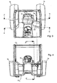
- is a plan view of the cab of
Figure 2 ; - Figure 4
- is a front view of the cab of
Figure 2 ; - Figure 5
- is a view of the section 5-5 shown in
Figure 4 showing a side view of the passenger seat in the seating position; - Figure 6
- is a perspective view of the section 6-6 shown in
Figure 3 shown with the driver's seat and steering wheel removed; - Figure 7
- is a perspective view of the section 7-7 shown in
Figure 3 shown with the driver's seat removed; - Figure 8
- is a perspective view of the section 6-6 shown in
Figure 3 shown with the driver's seat and steering wheel removed and showing the components of the passenger seat in exploded form; - Figure 9
- is an isometric perspective view of the tractor cab of
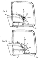
Figure 2 shown with the passenger seat in an intermediate position; - Figure 10
- is a plan view of the cab of
Figure 9 ; - Figure 11
- is a front view of the cab of
Figure 9 ; - Figure 12
- is a view of the section 12-12 shown in
Figure 11 showing a side view of the passenger seat in the intermediate position; - Figure 13
- is an isometric perspective view of the tractor cab of
Figure 2 shown with the passenger seat in a stowed position; - Figure 14
- is a plan view of the cab of
Figure 13 ; - Figure 15
- is a front view of the cab of
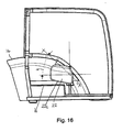
Figure 13 ; - Figure 16
- is a view of the section 16-16 shown in
Figure 15 showing a side view of the passenger seat in the stowed position. - To facilitate an understanding of the principles and features of the invention an illustrative embodiment is explained below. The terms 'forward', 'rearward' and 'transverse' as used herein are all referenced to the longitudinal centre line of the chassis of the tractor described moving in a forward direction.
- With reference to the drawings, a tractor 10 comprises wheels 11, a
cab 12 and a hood 13 which encloses an engine compartment (not shown). Thecab 12 comprises aroof 12a,upright support pillars 12b and afloor section 12c. It should be appreciated that the construction of thecab 12 shown inFigure 1 differs to that shown in the other drawings. - The rear wheels 11 are partly covered by
fenders 14 which extend inside thecab 12. A driver'sseat 15 is positioned centrally between thefenders 14 and is secured to a raisedsection 16 of thecab floor 12c. Theinside edge 14a offenders 14 provide an interior wall of thecab 12 and, on one side, provides the most suitable location for a passenger seat. - A
foldaway passenger seat 20 in accordance with the invention comprises aseat tray 22 formed of a mouldedplastic section 22a supported on a rigid steel plate section 22b (Fig. 8 ). The upper surface ofseat tray 22 provides a surface upon which a passenger can sit. - With particular reference to
Figures 6 ,7 and8 , to the underside of the rigid plate section 22b ofseat tray 22 twostruts sleeve 26 so as to radially extend therefrom. Together with the underside of theseat tray base 22a, thestruts struts seat tray 22. Thesleeve 26 fits on, and rotates around, a mountingshaft 28 which is secured to aframe member 30 by abracket 32 welded thereto. - The
frame member 30 may form part of the cab structure and has a profile which conforms with that of theinside edge 14a offender 14. Theframe member 30 shown in the drawings is formed of square section bent to the desired profile. However, other suitable materials are envisaged to provide the supporting structure. It should be appreciated that theframe member 30 may be secured independent of the cab structure but will be fixed in relation thereto. - The orientation of mounting
shaft 28 defines an axis X around which theseat tray 22 pivots between a substantially horizontal seating position (Figures 2 to 7 ) and a stowed position (Figures 13 to 16 ). Axis X is disposed at an angle a of 45 degrees to the horizontal (Fig. 16 ), at an angle β of 45 degrees to a transverse vertical plane (represented by line Y inFigures 5 and 12 ), and at an angle γ of 45 degrees to a longitudinal vertical plane (Figs. 10 and14 ). - From the end of mounting
shaft 28 that is secured tobracket 32 theshaft 28 extends rearwardly and upwardly and into the volume of the cab. Advantageously, in accordance with the invention theforward facing edge 22c of theseat tray 22 when in the seating position (Figures 5 and6 ) becomes the lower most edge when in the stowed position (Figure 16 ). Furthermore, theseat tray 22 can be folded between the two positions in one fluid pivoting movement. - To secure the
seat tray 22 in the seating position asupport element 34 is provided. Thesupport element 34 is pivotally secured to theframe member 30 at a position approximately 20cm from the top thereof. A securingelement 35 surrounds a tubular part of the supporting element so as to allow the pivoting motion. - The supporting
element 34 simply rests against theframe member 30 when not required. When the seat tray is lifted to the seated position the supportingelement 34 is pivoted upwardly and is engaged with acatch 36 which is secured to the underside of the rigid steel part 22b ofseat tray 22. Therefore, the supportingelement 34 and the mountingshaft 28 provide triangulated support for the weight uponseat tray 22. - The seat tray is simply moved to a stowed position by releasing
support element 34 fromcatch 36 and lowering the seat tray in one fluid move. - The dimensions, geometry and orientation of mounting
shaft 28 and struts 24,25 can be chosen to locate theseat tray 22 in the desired position, both when in the seating position and in the stowed position. Advantageously, the mountingshaft 28 which is angled in three dimensions provides a pivoting axis X which allows theseat tray 22 to extend forwardly of theframe member 30 when in the seating position whilst also positioning the seat tray at least partly rearwardly of the frame member when in the stowed position. Therefore, when stowed, the seat tray is located between the driver'sseat 15 and theinside edge 14a offender 14 ensuring that it does not cause an obstruction to the driver.
Claims (9)
- A utility vehicle (10) comprising a foldaway passenger seat (20), the seat comprising a seat tray (22) which can pivot around a single axis (X) between a substantially horizontal seating position and a substantially vertical stowed position, characterised in that a forward facing edge (22c) of the seat tray in the seating position is the lower-most edge and aligned longitudinally with respect to the vehicle when in the stowed position, wherein the axis (X) is within the range of 40 to 50 degrees to the horizontal and to a transverse vertical plane.
- A utility vehicle according to Claim 1, further comprising a fender, wherein the seat tray is mounted to the inside edge of the fender (14) and wherein the axis (X) extends from one end nearest the fender rearwardly and upwardly with respect to a forward direction of the utility vehicle.
- A utility vehicle according to Claim 1 or 2, comprising a cab (12), wherein the axis is defined by a mounting shaft (28) fixed relative to the cab.
- A utility vehicle according to Claim 3, wherein the seat tray is secured to a mounting element at one end, the mounting element being rotatably mounted to the mounting shaft.
- A utility vehicle according to Claim 4, wherein the mounting element comprises a sleeve (26) which fits and rotates on the mounting shaft.
- A utility vehicle according to Claim 5, wherein the mounting element further comprises at least one strut (24,25) secured between the sleeve (26) and the underside of the seat tray, the strut extending substantially radially from the sleeve.
- A utility vehicle according to Claim 5, wherein the mounting element comprises two struts (24, 25) secured to the seat base in a triangulated structure.
- A utility vehicle according to any one of Claims 3 to 7, wherein the cab comprises a frame member (30), and wherein the mounting shaft (28) is secured to the frame member.
- A utility vehicle according to any preceding claim, further comprising a supporting element (34) which is pivotally attached to the seat tray and engages with a catch (36) when in the seating position to support part of a users weight when seated.
Applications Claiming Priority (2)
| Application Number | Priority Date | Filing Date | Title |
|---|---|---|---|
| GB0903115A GB0903115D0 (en) | 2009-02-25 | 2009-02-25 | Foldaway passenger seat for utility vehicle |
| PCT/IB2010/000265 WO2010097669A1 (en) | 2009-02-25 | 2010-02-11 | Foldaway passenger seat for utility vehicle |
Publications (2)
| Publication Number | Publication Date |
|---|---|
| EP2401173A1 EP2401173A1 (en) | 2012-01-04 |
| EP2401173B1 true EP2401173B1 (en) | 2014-07-16 |
Family
ID=40565630
Family Applications (1)
| Application Number | Title | Priority Date | Filing Date |
|---|---|---|---|
| EP10708363.6A Active EP2401173B1 (en) | 2009-02-25 | 2010-02-11 | Foldaway passenger seat for utility vehicle |
Country Status (4)
| Country | Link |
|---|---|
| US (1) | US8960795B2 (en) |
| EP (1) | EP2401173B1 (en) |
| GB (1) | GB0903115D0 (en) |
| WO (1) | WO2010097669A1 (en) |
Families Citing this family (2)
| Publication number | Priority date | Publication date | Assignee | Title |
|---|---|---|---|---|
| US10525803B2 (en) | 2017-04-26 | 2020-01-07 | Undercover, Inc. | Cover including a monolithic coating |
| JP7120169B2 (en) * | 2019-06-28 | 2022-08-17 | トヨタ自動車株式会社 | vehicle seat |
Family Cites Families (23)
| Publication number | Priority date | Publication date | Assignee | Title |
|---|---|---|---|---|
| US427570A (en) * | 1890-05-13 | Opera-chair | ||
| US1395757A (en) * | 1915-10-05 | 1921-11-01 | John S Mcwhirter | Foldable seat for prepayment-cars |
| US2153155A (en) * | 1938-12-21 | 1939-04-04 | Stubnitz Greene Spring Corp | Seat |
| US2565695A (en) * | 1946-08-10 | 1951-08-28 | George A Lynn | Adjustable safety seat |
| US3116091A (en) * | 1960-12-09 | 1963-12-31 | Pacific Seating Corp | Stadium seat |
| US3131964A (en) * | 1962-11-13 | 1964-05-05 | Budd Co | Folding seat arrangement |
| US3376587A (en) * | 1966-07-21 | 1968-04-09 | Edward A. Staron | Folding seat and locker arrangement for a boat hull |
| US3463542A (en) * | 1968-04-22 | 1969-08-26 | Allis Chalmers Mfg Co | Swing-away seat |
| DE2617942A1 (en) | 1976-04-24 | 1977-10-27 | Daimler Benz Ag | Folding passenger seat for lorry - has folding back and support frame for compact stowage against forward bulkhead |
| US4632457A (en) | 1985-10-15 | 1986-12-30 | Seats Incorporated | Collapsible seat |
| DE3617292C1 (en) * | 1986-05-23 | 1987-07-09 | Case Gmbh J I | Driver's seat for commercial vehicles and farm tractors with a removable head-rest or neck-rest |
| US4884842A (en) * | 1988-08-08 | 1989-12-05 | Sarah Finkelstein | Body supporting chair |
| IT219148Z2 (en) | 1989-11-27 | 1992-12-11 | Same Spa | AUXILIARY SEAT FOR AGRICULTURAL TRACTORS |
| US5364151A (en) * | 1993-04-21 | 1994-11-15 | Mack Trucks, Inc. | Adjustable seat apparatus for utility vehicle |
| US5374106A (en) * | 1993-09-30 | 1994-12-20 | Agco Corporation | Folding auxiliary seat for tractor cab |
| US5516180A (en) * | 1993-12-15 | 1996-05-14 | Deere & Company | Prop and latch rod for a vehicle seat |
| US5524722A (en) * | 1994-11-22 | 1996-06-11 | New Holland North America, Inc. | Skid steer loader seat mechanism |
| US5797649A (en) * | 1996-12-02 | 1998-08-25 | Case Corporation | Folding auxiliary seat for a vehicle |
| FR2790927B1 (en) * | 1999-03-17 | 2001-06-01 | Delagrave | TILT SEAT SEAT |
| GB2355652A (en) * | 1999-11-01 | 2001-05-02 | New Holland | Folding spare seat for an agricultural vehicle |
| AUPS157802A0 (en) * | 2002-04-05 | 2002-05-16 | Sebel Furniture Limited | Pivotal mounting mechanism |
| US20060131941A1 (en) * | 2004-12-16 | 2006-06-22 | Hendron Scott S | Two way seat |
| US7914078B2 (en) * | 2005-10-31 | 2011-03-29 | Deere & Company | Adjustable lower seat for use with a stand and lean type backrest |
-
2009
- 2009-02-25 GB GB0903115A patent/GB0903115D0/en not_active Ceased
-
2010
- 2010-02-11 WO PCT/IB2010/000265 patent/WO2010097669A1/en not_active Ceased
- 2010-02-11 US US13/203,346 patent/US8960795B2/en active Active
- 2010-02-11 EP EP10708363.6A patent/EP2401173B1/en active Active
Also Published As
| Publication number | Publication date |
|---|---|
| GB0903115D0 (en) | 2009-04-08 |
| WO2010097669A1 (en) | 2010-09-02 |
| US8960795B2 (en) | 2015-02-24 |
| US20120043795A1 (en) | 2012-02-23 |
| EP2401173A1 (en) | 2012-01-04 |
Similar Documents
| Publication | Publication Date | Title |
|---|---|---|
| US6398291B1 (en) | Collapsible vehicle mid-gate with seat components fixed thereon | |
| JP5715156B2 (en) | Vehicle door mechanism | |
| US9056560B2 (en) | Seat assembly having a front cushion module | |
| CN100537293C (en) | Vehicle seating apparatus | |
| JP5214610B2 (en) | Vehicle seat | |
| EP2865560A1 (en) | Side by side all terrain vehicle | |
| US20070040406A1 (en) | Vehicle rear seating arrangement | |
| EP2855196B1 (en) | Fold and kneel seat wtih rearward folding motion | |
| US6158799A (en) | Seat positioning method and apparatus | |
| US8960795B2 (en) | Foldaway passenger seat for utility vehicle | |
| WO2005051704A1 (en) | Adjustable seat for a motor vehicle and a motor vehicle provided with said seat | |
| US20150298615A1 (en) | Wire tipped second row seatback with integrated storage | |
| CN104114405B (en) | Wide soft rear seat | |
| CN121778042A (en) | Vehicles with convertible front engine hood | |
| US20190031053A1 (en) | Collapsible storage enclosure for vehicle | |
| EP0990551A1 (en) | Automotive seating assembly | |
| FR2895336A1 (en) | RETRACTABLE HEADREST FOR MOTOR VEHICLE | |
| GB2517989A (en) | Vehicle seating | |
| CN107284296B (en) | Multifunctional automobile rear seat | |
| WO2009042409A1 (en) | Assist handle for vehicle seat | |
| FR2928897A1 (en) | Fascia crosspiece and steering column assembly for motor vehicle, has fascia crosspiece connected to steering column by support, such that crosspiece passes under steering column, where support is connected to main tube of crosspiece | |
| CN107284295B (en) | Multifunctional automobile back row seat | |
| EP1687179A1 (en) | Seat for a motor vehicle, and motor vehicle equipped with this seat | |
| EP4183622A1 (en) | Modular seat and vehicle comprising such modular seat | |
| US20080001425A1 (en) | Vehicle seat assembly |
Legal Events
| Date | Code | Title | Description |
|---|---|---|---|
| PUAI | Public reference made under article 153(3) epc to a published international application that has entered the european phase |
Free format text: ORIGINAL CODE: 0009012 |
|
| 17P | Request for examination filed |
Effective date: 20110926 |
|
| AK | Designated contracting states |
Kind code of ref document: A1 Designated state(s): AT BE BG CH CY CZ DE DK EE ES FI FR GB GR HR HU IE IS IT LI LT LU LV MC MK MT NL NO PL PT RO SE SI SK SM TR |
|
| RIN1 | Information on inventor provided before grant (corrected) |
Inventor name: SAP, BRUNO |
|
| DAX | Request for extension of the european patent (deleted) | ||
| 17Q | First examination report despatched |
Effective date: 20131023 |
|
| GRAP | Despatch of communication of intention to grant a patent |
Free format text: ORIGINAL CODE: EPIDOSNIGR1 |
|
| INTG | Intention to grant announced |
Effective date: 20140416 |
|
| GRAS | Grant fee paid |
Free format text: ORIGINAL CODE: EPIDOSNIGR3 |
|
| GRAA | (expected) grant |
Free format text: ORIGINAL CODE: 0009210 |
|
| AK | Designated contracting states |
Kind code of ref document: B1 Designated state(s): AT BE BG CH CY CZ DE DK EE ES FI FR GB GR HR HU IE IS IT LI LT LU LV MC MK MT NL NO PL PT RO SE SI SK SM TR |
|
| REG | Reference to a national code |
Ref country code: GB Ref legal event code: FG4D |
|
| REG | Reference to a national code |
Ref country code: CH Ref legal event code: EP |
|
| REG | Reference to a national code |
Ref country code: IE Ref legal event code: FG4D |
|
| REG | Reference to a national code |
Ref country code: AT Ref legal event code: REF Ref document number: 677395 Country of ref document: AT Kind code of ref document: T Effective date: 20140815 |
|
| REG | Reference to a national code |
Ref country code: DE Ref legal event code: R096 Ref document number: 602010017480 Country of ref document: DE Effective date: 20140828 |
|
| REG | Reference to a national code |
Ref country code: NL Ref legal event code: VDEP Effective date: 20140716 |
|
| REG | Reference to a national code |
Ref country code: AT Ref legal event code: MK05 Ref document number: 677395 Country of ref document: AT Kind code of ref document: T Effective date: 20140716 |
|
| REG | Reference to a national code |
Ref country code: LT Ref legal event code: MG4D |
|
| PG25 | Lapsed in a contracting state [announced via postgrant information from national office to epo] |
Ref country code: ES Free format text: LAPSE BECAUSE OF FAILURE TO SUBMIT A TRANSLATION OF THE DESCRIPTION OR TO PAY THE FEE WITHIN THE PRESCRIBED TIME-LIMIT Effective date: 20140716 Ref country code: LT Free format text: LAPSE BECAUSE OF FAILURE TO SUBMIT A TRANSLATION OF THE DESCRIPTION OR TO PAY THE FEE WITHIN THE PRESCRIBED TIME-LIMIT Effective date: 20140716 Ref country code: PT Free format text: LAPSE BECAUSE OF FAILURE TO SUBMIT A TRANSLATION OF THE DESCRIPTION OR TO PAY THE FEE WITHIN THE PRESCRIBED TIME-LIMIT Effective date: 20141117 Ref country code: SE Free format text: LAPSE BECAUSE OF FAILURE TO SUBMIT A TRANSLATION OF THE DESCRIPTION OR TO PAY THE FEE WITHIN THE PRESCRIBED TIME-LIMIT Effective date: 20140716 Ref country code: NO Free format text: LAPSE BECAUSE OF FAILURE TO SUBMIT A TRANSLATION OF THE DESCRIPTION OR TO PAY THE FEE WITHIN THE PRESCRIBED TIME-LIMIT Effective date: 20141016 Ref country code: BG Free format text: LAPSE BECAUSE OF FAILURE TO SUBMIT A TRANSLATION OF THE DESCRIPTION OR TO PAY THE FEE WITHIN THE PRESCRIBED TIME-LIMIT Effective date: 20141016 Ref country code: GR Free format text: LAPSE BECAUSE OF FAILURE TO SUBMIT A TRANSLATION OF THE DESCRIPTION OR TO PAY THE FEE WITHIN THE PRESCRIBED TIME-LIMIT Effective date: 20141017 Ref country code: FI Free format text: LAPSE BECAUSE OF FAILURE TO SUBMIT A TRANSLATION OF THE DESCRIPTION OR TO PAY THE FEE WITHIN THE PRESCRIBED TIME-LIMIT Effective date: 20140716 |
|
| REG | Reference to a national code |
Ref country code: FR Ref legal event code: PLFP Year of fee payment: 6 |
|
| PG25 | Lapsed in a contracting state [announced via postgrant information from national office to epo] |
Ref country code: PL Free format text: LAPSE BECAUSE OF FAILURE TO SUBMIT A TRANSLATION OF THE DESCRIPTION OR TO PAY THE FEE WITHIN THE PRESCRIBED TIME-LIMIT Effective date: 20140716 Ref country code: NL Free format text: LAPSE BECAUSE OF FAILURE TO SUBMIT A TRANSLATION OF THE DESCRIPTION OR TO PAY THE FEE WITHIN THE PRESCRIBED TIME-LIMIT Effective date: 20140716 Ref country code: IS Free format text: LAPSE BECAUSE OF FAILURE TO SUBMIT A TRANSLATION OF THE DESCRIPTION OR TO PAY THE FEE WITHIN THE PRESCRIBED TIME-LIMIT Effective date: 20141116 Ref country code: LV Free format text: LAPSE BECAUSE OF FAILURE TO SUBMIT A TRANSLATION OF THE DESCRIPTION OR TO PAY THE FEE WITHIN THE PRESCRIBED TIME-LIMIT Effective date: 20140716 Ref country code: AT Free format text: LAPSE BECAUSE OF FAILURE TO SUBMIT A TRANSLATION OF THE DESCRIPTION OR TO PAY THE FEE WITHIN THE PRESCRIBED TIME-LIMIT Effective date: 20140716 Ref country code: CY Free format text: LAPSE BECAUSE OF FAILURE TO SUBMIT A TRANSLATION OF THE DESCRIPTION OR TO PAY THE FEE WITHIN THE PRESCRIBED TIME-LIMIT Effective date: 20140716 |
|
| REG | Reference to a national code |
Ref country code: DE Ref legal event code: R097 Ref document number: 602010017480 Country of ref document: DE |
|
| PG25 | Lapsed in a contracting state [announced via postgrant information from national office to epo] |
Ref country code: SK Free format text: LAPSE BECAUSE OF FAILURE TO SUBMIT A TRANSLATION OF THE DESCRIPTION OR TO PAY THE FEE WITHIN THE PRESCRIBED TIME-LIMIT Effective date: 20140716 Ref country code: CZ Free format text: LAPSE BECAUSE OF FAILURE TO SUBMIT A TRANSLATION OF THE DESCRIPTION OR TO PAY THE FEE WITHIN THE PRESCRIBED TIME-LIMIT Effective date: 20140716 Ref country code: EE Free format text: LAPSE BECAUSE OF FAILURE TO SUBMIT A TRANSLATION OF THE DESCRIPTION OR TO PAY THE FEE WITHIN THE PRESCRIBED TIME-LIMIT Effective date: 20140716 Ref country code: RO Free format text: LAPSE BECAUSE OF FAILURE TO SUBMIT A TRANSLATION OF THE DESCRIPTION OR TO PAY THE FEE WITHIN THE PRESCRIBED TIME-LIMIT Effective date: 20140716 Ref country code: DK Free format text: LAPSE BECAUSE OF FAILURE TO SUBMIT A TRANSLATION OF THE DESCRIPTION OR TO PAY THE FEE WITHIN THE PRESCRIBED TIME-LIMIT Effective date: 20140716 |
|
| PLBE | No opposition filed within time limit |
Free format text: ORIGINAL CODE: 0009261 |
|
| STAA | Information on the status of an ep patent application or granted ep patent |
Free format text: STATUS: NO OPPOSITION FILED WITHIN TIME LIMIT |
|
| 26N | No opposition filed |
Effective date: 20150417 |
|
| PG25 | Lapsed in a contracting state [announced via postgrant information from national office to epo] |
Ref country code: BE Free format text: LAPSE BECAUSE OF NON-PAYMENT OF DUE FEES Effective date: 20150228 |
|
| PG25 | Lapsed in a contracting state [announced via postgrant information from national office to epo] |
Ref country code: LU Free format text: LAPSE BECAUSE OF FAILURE TO SUBMIT A TRANSLATION OF THE DESCRIPTION OR TO PAY THE FEE WITHIN THE PRESCRIBED TIME-LIMIT Effective date: 20150211 |
|
| REG | Reference to a national code |
Ref country code: CH Ref legal event code: PL |
|
| PG25 | Lapsed in a contracting state [announced via postgrant information from national office to epo] |
Ref country code: LI Free format text: LAPSE BECAUSE OF NON-PAYMENT OF DUE FEES Effective date: 20150228 Ref country code: CH Free format text: LAPSE BECAUSE OF NON-PAYMENT OF DUE FEES Effective date: 20150228 Ref country code: MC Free format text: LAPSE BECAUSE OF FAILURE TO SUBMIT A TRANSLATION OF THE DESCRIPTION OR TO PAY THE FEE WITHIN THE PRESCRIBED TIME-LIMIT Effective date: 20140716 |
|
| REG | Reference to a national code |
Ref country code: IE Ref legal event code: MM4A |
|
| PG25 | Lapsed in a contracting state [announced via postgrant information from national office to epo] |
Ref country code: SI Free format text: LAPSE BECAUSE OF FAILURE TO SUBMIT A TRANSLATION OF THE DESCRIPTION OR TO PAY THE FEE WITHIN THE PRESCRIBED TIME-LIMIT Effective date: 20140716 |
|
| PG25 | Lapsed in a contracting state [announced via postgrant information from national office to epo] |
Ref country code: IE Free format text: LAPSE BECAUSE OF NON-PAYMENT OF DUE FEES Effective date: 20150211 |
|
| REG | Reference to a national code |
Ref country code: FR Ref legal event code: PLFP Year of fee payment: 7 |
|
| PG25 | Lapsed in a contracting state [announced via postgrant information from national office to epo] |
Ref country code: BE Free format text: LAPSE BECAUSE OF FAILURE TO SUBMIT A TRANSLATION OF THE DESCRIPTION OR TO PAY THE FEE WITHIN THE PRESCRIBED TIME-LIMIT Effective date: 20140716 |
|
| PG25 | Lapsed in a contracting state [announced via postgrant information from national office to epo] |
Ref country code: MT Free format text: LAPSE BECAUSE OF FAILURE TO SUBMIT A TRANSLATION OF THE DESCRIPTION OR TO PAY THE FEE WITHIN THE PRESCRIBED TIME-LIMIT Effective date: 20140716 |
|
| REG | Reference to a national code |
Ref country code: FR Ref legal event code: PLFP Year of fee payment: 8 |
|
| PG25 | Lapsed in a contracting state [announced via postgrant information from national office to epo] |
Ref country code: SM Free format text: LAPSE BECAUSE OF FAILURE TO SUBMIT A TRANSLATION OF THE DESCRIPTION OR TO PAY THE FEE WITHIN THE PRESCRIBED TIME-LIMIT Effective date: 20140716 Ref country code: HU Free format text: LAPSE BECAUSE OF FAILURE TO SUBMIT A TRANSLATION OF THE DESCRIPTION OR TO PAY THE FEE WITHIN THE PRESCRIBED TIME-LIMIT; INVALID AB INITIO Effective date: 20100211 |
|
| PG25 | Lapsed in a contracting state [announced via postgrant information from national office to epo] |
Ref country code: HR Free format text: LAPSE BECAUSE OF FAILURE TO SUBMIT A TRANSLATION OF THE DESCRIPTION OR TO PAY THE FEE WITHIN THE PRESCRIBED TIME-LIMIT Effective date: 20140716 |
|
| PG25 | Lapsed in a contracting state [announced via postgrant information from national office to epo] |
Ref country code: TR Free format text: LAPSE BECAUSE OF FAILURE TO SUBMIT A TRANSLATION OF THE DESCRIPTION OR TO PAY THE FEE WITHIN THE PRESCRIBED TIME-LIMIT Effective date: 20140716 |
|
| REG | Reference to a national code |
Ref country code: FR Ref legal event code: PLFP Year of fee payment: 9 |
|
| PG25 | Lapsed in a contracting state [announced via postgrant information from national office to epo] |
Ref country code: MK Free format text: LAPSE BECAUSE OF FAILURE TO SUBMIT A TRANSLATION OF THE DESCRIPTION OR TO PAY THE FEE WITHIN THE PRESCRIBED TIME-LIMIT Effective date: 20140716 |
|
| PGFP | Annual fee paid to national office [announced via postgrant information from national office to epo] |
Ref country code: GB Payment date: 20220223 Year of fee payment: 13 |
|
| PGFP | Annual fee paid to national office [announced via postgrant information from national office to epo] |
Ref country code: IT Payment date: 20220217 Year of fee payment: 13 |
|
| GBPC | Gb: european patent ceased through non-payment of renewal fee |
Effective date: 20230211 |
|
| PG25 | Lapsed in a contracting state [announced via postgrant information from national office to epo] |
Ref country code: GB Free format text: LAPSE BECAUSE OF NON-PAYMENT OF DUE FEES Effective date: 20230211 |
|
| PG25 | Lapsed in a contracting state [announced via postgrant information from national office to epo] |
Ref country code: IT Free format text: LAPSE BECAUSE OF NON-PAYMENT OF DUE FEES Effective date: 20230211 Ref country code: GB Free format text: LAPSE BECAUSE OF NON-PAYMENT OF DUE FEES Effective date: 20230211 |
|
| PGFP | Annual fee paid to national office [announced via postgrant information from national office to epo] |
Ref country code: DE Payment date: 20240219 Year of fee payment: 15 |
|
| PGFP | Annual fee paid to national office [announced via postgrant information from national office to epo] |
Ref country code: FR Payment date: 20250221 Year of fee payment: 16 |
|
| REG | Reference to a national code |
Ref country code: DE Ref legal event code: R119 Ref document number: 602010017480 Country of ref document: DE |
|
| PG25 | Lapsed in a contracting state [announced via postgrant information from national office to epo] |
Ref country code: DE Free format text: LAPSE BECAUSE OF NON-PAYMENT OF DUE FEES Effective date: 20250902 |