EP2401142B1 - Bande pour réaliser des unités remplies de fluide - Google Patents
Bande pour réaliser des unités remplies de fluide Download PDFInfo
- Publication number
- EP2401142B1 EP2401142B1 EP09789543.7A EP09789543A EP2401142B1 EP 2401142 B1 EP2401142 B1 EP 2401142B1 EP 09789543 A EP09789543 A EP 09789543A EP 2401142 B1 EP2401142 B1 EP 2401142B1
- Authority
- EP
- European Patent Office
- Prior art keywords
- perforations
- web
- inflation
- forming area
- pouches
- Prior art date
- Legal status (The legal status is an assumption and is not a legal conclusion. Google has not performed a legal analysis and makes no representation as to the accuracy of the status listed.)
- Active
Links
- 239000012530 fluid Substances 0.000 title claims description 25
- 241000238876 Acari Species 0.000 claims description 3
- 238000004891 communication Methods 0.000 claims description 2
- 230000007704 transition Effects 0.000 claims description 2
- 239000010410 layer Substances 0.000 description 34
- 238000000034 method Methods 0.000 description 21
- 230000008569 process Effects 0.000 description 15
- 238000007789 sealing Methods 0.000 description 11
- 239000004033 plastic Substances 0.000 description 10
- 229920003023 plastic Polymers 0.000 description 10
- 238000001816 cooling Methods 0.000 description 8
- 239000000463 material Substances 0.000 description 7
- 230000037303 wrinkles Effects 0.000 description 7
- 238000010438 heat treatment Methods 0.000 description 4
- 230000007480 spreading Effects 0.000 description 3
- 239000004698 Polyethylene Substances 0.000 description 2
- 230000006978 adaptation Effects 0.000 description 2
- 238000003491 array Methods 0.000 description 2
- 230000008901 benefit Effects 0.000 description 2
- 238000006243 chemical reaction Methods 0.000 description 2
- 238000012986 modification Methods 0.000 description 2
- 230000004048 modification Effects 0.000 description 2
- 239000002985 plastic film Substances 0.000 description 2
- 229920006255 plastic film Polymers 0.000 description 2
- -1 polyethylene Polymers 0.000 description 2
- 229920000573 polyethylene Polymers 0.000 description 2
- XAGFODPZIPBFFR-UHFFFAOYSA-N aluminium Chemical group [Al] XAGFODPZIPBFFR-UHFFFAOYSA-N 0.000 description 1
- 229910052782 aluminium Inorganic materials 0.000 description 1
- 230000001010 compromised effect Effects 0.000 description 1
- 238000011161 development Methods 0.000 description 1
- 230000008030 elimination Effects 0.000 description 1
- 238000003379 elimination reaction Methods 0.000 description 1
- 238000009434 installation Methods 0.000 description 1
- 230000009467 reduction Effects 0.000 description 1
- 230000000452 restraining effect Effects 0.000 description 1
- 239000002356 single layer Substances 0.000 description 1
Images


Classifications
-
- B—PERFORMING OPERATIONS; TRANSPORTING
- B65—CONVEYING; PACKING; STORING; HANDLING THIN OR FILAMENTARY MATERIAL
- B65D—CONTAINERS FOR STORAGE OR TRANSPORT OF ARTICLES OR MATERIALS, e.g. BAGS, BARRELS, BOTTLES, BOXES, CANS, CARTONS, CRATES, DRUMS, JARS, TANKS, HOPPERS, FORWARDING CONTAINERS; ACCESSORIES, CLOSURES, OR FITTINGS THEREFOR; PACKAGING ELEMENTS; PACKAGES
- B65D81/00—Containers, packaging elements, or packages, for contents presenting particular transport or storage problems, or adapted to be used for non-packaging purposes after removal of contents
- B65D81/02—Containers, packaging elements, or packages, for contents presenting particular transport or storage problems, or adapted to be used for non-packaging purposes after removal of contents specially adapted to protect contents from mechanical damage
- B65D81/05—Containers, packaging elements, or packages, for contents presenting particular transport or storage problems, or adapted to be used for non-packaging purposes after removal of contents specially adapted to protect contents from mechanical damage maintaining contents at spaced relation from package walls, or from other contents
- B65D81/051—Containers, packaging elements, or packages, for contents presenting particular transport or storage problems, or adapted to be used for non-packaging purposes after removal of contents specially adapted to protect contents from mechanical damage maintaining contents at spaced relation from package walls, or from other contents using pillow-like elements filled with cushioning material, e.g. elastic foam, fabric
- B65D81/052—Containers, packaging elements, or packages, for contents presenting particular transport or storage problems, or adapted to be used for non-packaging purposes after removal of contents specially adapted to protect contents from mechanical damage maintaining contents at spaced relation from package walls, or from other contents using pillow-like elements filled with cushioning material, e.g. elastic foam, fabric filled with fluid, e.g. inflatable elements
-
- B—PERFORMING OPERATIONS; TRANSPORTING
- B31—MAKING ARTICLES OF PAPER, CARDBOARD OR MATERIAL WORKED IN A MANNER ANALOGOUS TO PAPER; WORKING PAPER, CARDBOARD OR MATERIAL WORKED IN A MANNER ANALOGOUS TO PAPER
- B31D—MAKING ARTICLES OF PAPER, CARDBOARD OR MATERIAL WORKED IN A MANNER ANALOGOUS TO PAPER, NOT PROVIDED FOR IN SUBCLASSES B31B OR B31C
- B31D5/00—Multiple-step processes for making three-dimensional articles ; Making three-dimensional articles
- B31D5/0039—Multiple-step processes for making three-dimensional articles ; Making three-dimensional articles for making dunnage or cushion pads
- B31D5/0073—Multiple-step processes for making three-dimensional articles ; Making three-dimensional articles for making dunnage or cushion pads including pillow forming
-
- B—PERFORMING OPERATIONS; TRANSPORTING
- B32—LAYERED PRODUCTS
- B32B—LAYERED PRODUCTS, i.e. PRODUCTS BUILT-UP OF STRATA OF FLAT OR NON-FLAT, e.g. CELLULAR OR HONEYCOMB, FORM
- B32B1/00—Layered products having a general shape other than plane
- B32B1/08—Tubular products
-
- B—PERFORMING OPERATIONS; TRANSPORTING
- B32—LAYERED PRODUCTS
- B32B—LAYERED PRODUCTS, i.e. PRODUCTS BUILT-UP OF STRATA OF FLAT OR NON-FLAT, e.g. CELLULAR OR HONEYCOMB, FORM
- B32B3/00—Layered products comprising a layer with external or internal discontinuities or unevennesses, or a layer of non-planar form; Layered products having particular features of form
- B32B3/26—Layered products comprising a layer with external or internal discontinuities or unevennesses, or a layer of non-planar form; Layered products having particular features of form characterised by a particular shape of the outline of the cross-section of a continuous layer; characterised by a layer with cavities or internal voids ; characterised by an apertured layer
- B32B3/266—Layered products comprising a layer with external or internal discontinuities or unevennesses, or a layer of non-planar form; Layered products having particular features of form characterised by a particular shape of the outline of the cross-section of a continuous layer; characterised by a layer with cavities or internal voids ; characterised by an apertured layer characterised by an apertured layer, the apertures going through the whole thickness of the layer, e.g. expanded metal, perforated layer, slit layer regular cells B32B3/12
-
- B—PERFORMING OPERATIONS; TRANSPORTING
- B32—LAYERED PRODUCTS
- B32B—LAYERED PRODUCTS, i.e. PRODUCTS BUILT-UP OF STRATA OF FLAT OR NON-FLAT, e.g. CELLULAR OR HONEYCOMB, FORM
- B32B7/00—Layered products characterised by the relation between layers; Layered products characterised by the relative orientation of features between layers, or by the relative values of a measurable parameter between layers, i.e. products comprising layers having different physical, chemical or physicochemical properties; Layered products characterised by the interconnection of layers
- B32B7/04—Interconnection of layers
- B32B7/06—Interconnection of layers permitting easy separation
-
- B—PERFORMING OPERATIONS; TRANSPORTING
- B65—CONVEYING; PACKING; STORING; HANDLING THIN OR FILAMENTARY MATERIAL
- B65D—CONTAINERS FOR STORAGE OR TRANSPORT OF ARTICLES OR MATERIALS, e.g. BAGS, BARRELS, BOTTLES, BOXES, CANS, CARTONS, CRATES, DRUMS, JARS, TANKS, HOPPERS, FORWARDING CONTAINERS; ACCESSORIES, CLOSURES, OR FITTINGS THEREFOR; PACKAGING ELEMENTS; PACKAGES
- B65D81/00—Containers, packaging elements, or packages, for contents presenting particular transport or storage problems, or adapted to be used for non-packaging purposes after removal of contents
- B65D81/02—Containers, packaging elements, or packages, for contents presenting particular transport or storage problems, or adapted to be used for non-packaging purposes after removal of contents specially adapted to protect contents from mechanical damage
- B65D81/05—Containers, packaging elements, or packages, for contents presenting particular transport or storage problems, or adapted to be used for non-packaging purposes after removal of contents specially adapted to protect contents from mechanical damage maintaining contents at spaced relation from package walls, or from other contents
- B65D81/051—Containers, packaging elements, or packages, for contents presenting particular transport or storage problems, or adapted to be used for non-packaging purposes after removal of contents specially adapted to protect contents from mechanical damage maintaining contents at spaced relation from package walls, or from other contents using pillow-like elements filled with cushioning material, e.g. elastic foam, fabric
-
- B—PERFORMING OPERATIONS; TRANSPORTING
- B31—MAKING ARTICLES OF PAPER, CARDBOARD OR MATERIAL WORKED IN A MANNER ANALOGOUS TO PAPER; WORKING PAPER, CARDBOARD OR MATERIAL WORKED IN A MANNER ANALOGOUS TO PAPER
- B31D—MAKING ARTICLES OF PAPER, CARDBOARD OR MATERIAL WORKED IN A MANNER ANALOGOUS TO PAPER, NOT PROVIDED FOR IN SUBCLASSES B31B OR B31C
- B31D2205/00—Multiple-step processes for making three-dimensional articles
- B31D2205/0005—Multiple-step processes for making three-dimensional articles for making dunnage or cushion pads
- B31D2205/0011—Multiple-step processes for making three-dimensional articles for making dunnage or cushion pads including particular additional operations
- B31D2205/0052—Perforating; Forming lines of weakness
-
- B—PERFORMING OPERATIONS; TRANSPORTING
- B31—MAKING ARTICLES OF PAPER, CARDBOARD OR MATERIAL WORKED IN A MANNER ANALOGOUS TO PAPER; WORKING PAPER, CARDBOARD OR MATERIAL WORKED IN A MANNER ANALOGOUS TO PAPER
- B31D—MAKING ARTICLES OF PAPER, CARDBOARD OR MATERIAL WORKED IN A MANNER ANALOGOUS TO PAPER, NOT PROVIDED FOR IN SUBCLASSES B31B OR B31C
- B31D2205/00—Multiple-step processes for making three-dimensional articles
- B31D2205/0005—Multiple-step processes for making three-dimensional articles for making dunnage or cushion pads
- B31D2205/0011—Multiple-step processes for making three-dimensional articles for making dunnage or cushion pads including particular additional operations
- B31D2205/0058—Cutting; Individualising the final products
-
- B—PERFORMING OPERATIONS; TRANSPORTING
- B32—LAYERED PRODUCTS
- B32B—LAYERED PRODUCTS, i.e. PRODUCTS BUILT-UP OF STRATA OF FLAT OR NON-FLAT, e.g. CELLULAR OR HONEYCOMB, FORM
- B32B1/00—Layered products having a general shape other than plane
-
- B—PERFORMING OPERATIONS; TRANSPORTING
- B32—LAYERED PRODUCTS
- B32B—LAYERED PRODUCTS, i.e. PRODUCTS BUILT-UP OF STRATA OF FLAT OR NON-FLAT, e.g. CELLULAR OR HONEYCOMB, FORM
- B32B2250/00—Layers arrangement
- B32B2250/02—2 layers
-
- B—PERFORMING OPERATIONS; TRANSPORTING
- B32—LAYERED PRODUCTS
- B32B—LAYERED PRODUCTS, i.e. PRODUCTS BUILT-UP OF STRATA OF FLAT OR NON-FLAT, e.g. CELLULAR OR HONEYCOMB, FORM
- B32B2307/00—Properties of the layers or laminate
- B32B2307/70—Other properties
- B32B2307/724—Permeability to gases, adsorption
- B32B2307/7242—Non-permeable
-
- B—PERFORMING OPERATIONS; TRANSPORTING
- B32—LAYERED PRODUCTS
- B32B—LAYERED PRODUCTS, i.e. PRODUCTS BUILT-UP OF STRATA OF FLAT OR NON-FLAT, e.g. CELLULAR OR HONEYCOMB, FORM
- B32B2553/00—Packaging equipment or accessories not otherwise provided for
- B32B2553/02—Shock absorbing
- B32B2553/023—Shock absorbing for use in loose form, e.g. dunnage
-
- Y—GENERAL TAGGING OF NEW TECHNOLOGICAL DEVELOPMENTS; GENERAL TAGGING OF CROSS-SECTIONAL TECHNOLOGIES SPANNING OVER SEVERAL SECTIONS OF THE IPC; TECHNICAL SUBJECTS COVERED BY FORMER USPC CROSS-REFERENCE ART COLLECTIONS [XRACs] AND DIGESTS
- Y10—TECHNICAL SUBJECTS COVERED BY FORMER USPC
- Y10T—TECHNICAL SUBJECTS COVERED BY FORMER US CLASSIFICATION
- Y10T428/00—Stock material or miscellaneous articles
- Y10T428/13—Hollow or container type article [e.g., tube, vase, etc.]
- Y10T428/1334—Nonself-supporting tubular film or bag [e.g., pouch, envelope, packet, etc.]
-
- Y—GENERAL TAGGING OF NEW TECHNOLOGICAL DEVELOPMENTS; GENERAL TAGGING OF CROSS-SECTIONAL TECHNOLOGIES SPANNING OVER SEVERAL SECTIONS OF THE IPC; TECHNICAL SUBJECTS COVERED BY FORMER USPC CROSS-REFERENCE ART COLLECTIONS [XRACs] AND DIGESTS
- Y10—TECHNICAL SUBJECTS COVERED BY FORMER USPC
- Y10T—TECHNICAL SUBJECTS COVERED BY FORMER US CLASSIFICATION
- Y10T428/00—Stock material or miscellaneous articles
- Y10T428/13—Hollow or container type article [e.g., tube, vase, etc.]
- Y10T428/1352—Polymer or resin containing [i.e., natural or synthetic]
- Y10T428/139—Open-ended, self-supporting conduit, cylinder, or tube-type article
- Y10T428/1393—Multilayer [continuous layer]
Definitions
- the present application relates to fluid filled units and more particularly to plastic webs of interconnected pouches and to processes of converting interconnected pouches to fluid filled units.
- Machines for forming and filling dunnage units from sheets of plastic are known.
- Machines which produce dunnage units by inflating preformed pouches in a preformed web are also known. For many applications, machines which utilize preformed webs are preferred.
- the present invention relates to a web for forming dunnage units according to claim 1.
- the webs include first and second elongated layers.
- a plurality of seals that hermetically join the first elongated layer to the second elongated layer to form a plurality of inflatable pouches and an inflation channel that is in fluid communication with pouches and is disposed outside of the pouches.
- An inflation side line of perforations, a gap forming area, and an opposite side line of perforations are arranged in a line between pair(s) of the pouches.
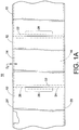
- each edge 18, 20 is either a fold or a seal that connects the superposed layers 14, 16 along the edges 18, 20.
- the connection at the opposite edge 20 is illustrated as a hermetic seal and the connection at the inflation edge 18 is illustrated as a fold in Figure 1 .
- the fold and the seal could be reversed or both of the connections could be seals in the Figure 1 embodiment.
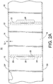
- the inflation edge 18 comprises a frangible connection 21 and the opposite edge 20 is a hermetic seal.
- the illustrated frangible connection 21 is a line of perforations. The size of the perforations is exaggerated to clarify Figure 2 .
- the frangible connection 21 may be formed by folding the inflation edge 18 and pulling the inflation edge over a serration forming wheel (not shown).
- Figure 2A illustrates a web 10 of inflatable pouches 12 in which a frangible connection 21' is present in one of the superposed layers, in the described embodiment layer 14, at a location offset from the inflation edge 18 by a distance D 4 .
- the distance D 4 is between 0.19 and 0.51 cm (0.075 and 0.2 inches), in an exemplary embodiment between 0.24 and 0.40 cm (0.09375 and 0.15625 inches).
- the frangible connection can be formed in a wide variety of different ways any of which can be used.
- the frangible connection 21' can be formed by pulling the web over a serration forming wheel (not shown) prior to folding the inflation edge or by providing a serration backing plate (not shown) interposed between the layers where the serration forming wheel contacts the web so that only a single layer is acted on by the wheel.
- each transverse seal 22 joins the top and bottom layers 14, 16.
- each transverse seal 22 extends from the opposite edge 20 to within a short distance of the inflation edge 18.
- Spaced pairs of lines of perforations 24, 26 extend through the top and bottom layers terminating a short distance from the edges 18, 20 respectively.
- a gap forming area 28 extends between each associated pair of lines of perforations 24, 26. The gap forming area 28 opens to form a gap 13 when the pouches are inflated (see Figure 3 ).
- a gap forming area 28 denotes an area, preferably linear in shape, that will rupture or otherwise separate when exposed to a predetermined inflation force.
- the magnitude of the inflation force is less than the magnitude of the force needed to rupture or separate the spaced apart lines of perforations 24, 26.
- the gap forming area 28 can take on a number of embodiments, as will be discussed below. Any method that produces an area between the spaced apart lines of perforations 24, 26 that ruptures or otherwise separates at a force lower than a force needed to rupture or separate spaced lines of perforations 24, 26 may be employed to make the gap forming area 28.
- dunnage units 12' are configured to be much easier to separate from one another than prior art arrays of dunnage units.
- each adjacent pair of dunnage units 12' is connected together by a pair of spaced apart lines of perforations 24,26.
- the spaced apart lines of perforations 24, 26 are spaced apart by a gap 13.
- a single row 11 of dunnage units 12' can be graphically described as being in a "ladder" configuration. This configuration makes separating two adjacent dunnage units 12' much easier than separating prior art arrays of dunnage units.
- a worker To separate a pair of adjacent dunnage units 12, a worker simply inserts an object or objects, such as a hand or hands, into the gap 13 and pulls one dunnage unit 12' away from the other dunnage unit 12'.
- a mechanical system can be used to separate dunnage units 12'.
- a machine can be configured to insert an object between adjacent dunnage units 12' and apply a force to separate the units
- a pouch prior to conversion to a dunnage unit, a pouch is typically hermetically sealed on three sides, leaving one side open to allow for inflation. Once the pouch is inflated, the inflation opening is hermetically sealed and the dunnage unit is formed. During the inflation process, as the volume of the pouch increases the sides of the pouch have a tendency to draw inward. Drawing the sides of the pouches inward will shorten the length of the sides of the pouch unless the sides of the pouch are constrained. In this application, the term foreshortening refers to the tendency of the length of a pouch side to shorten as the pouch is inflated.
- the sides of the pouch are restrained, because sides of adjacent pouches are connected by lines of perforations that extend along the entire length of the pouches and remain intact during and after inflation.
- the foreshortening of the unrestrained sides, such as the inflation opening may not be uniform. Restraining the sides of adjacent connected pouches can cause undesirable inflation induced stresses. These undesirable stresses caused because sides of adjacent pouches are connected and restrained, thus, limiting inflation and causing wrinkles to develop in the layers at the unrestrained inflation opening.
- the wrinkles can extend into a section of the inflation opening to be sealed to complete the dunnage unit, which may comprise the seal.
- One reason the seal can be compromised is that wrinkling can cause sections of the layers 14, 16 to fold on top of one another.
- a sealing station of a dunnage machine is typically set to apply the appropriate amount of heat to seal two layers of material.
- the sealing of multiple layers of material in the area of a wrinkle results in a seal that is weaker than remaining seal areas and may result in a small leak or tendency to rupture at loads lower than loads at which the dunnage units is designed to rupture.
- the gap forming area 28 produces a gap 13 between adjacent pouches upon inflation.
- the gap allows foreshortening of the connected pouch sides and thereby reduces the undesirable stresses that are introduced during inflation as compared with prior art webs.
- the web with a gap 13 facilitates fuller inflation of each pouch.
- the gap 13 maintains the inflation opening substantially free of wrinkles as the inflation opening is sealed to convert the inflated pouches to a dunnage units.
- the illustrated web 10 is constructed from a heat sealable plastic film, such as polyethylene.
- the web 10 is designed to accommodate a process for inflating each pouch 12 in the web to create a row or ladder 11 of dunnage units 12'.
- the gap forming area 28 creates a gap 13 between dunnage units 12', which facilitate a efficient and effective process for separating adjacent dunnage units 12' in the row or ladder 11.
- the gap forming area 28 defined by the web 10' includes an easily breakable line of perforations 29 between the spaced lines of perforations 24, 26.
- the force needed to rupture or separate the line of perforations 29 is less than the force needed to separate the perforations 24, 26 extending inward of the web edges 18, 20.
- Each pair of perforations 24, 26 and associated more easily breakable line of perforations 29 divide the transverse seal 22 into two transverse sections.
- the line of perforation 29 begins to rupture or separate leading to the development of a gap 13 between the produced dunnage units 12' (See Figure 3 ).
- the line of perforations 29 is fully or nearly fully ruptured; however the perforations 24, 26 at the edges remain intact. These perforations 24, 26 are ruptured or separated when a worker or automated process mechanically separates the perforations 24, 26.
- Figure 5 illustrates another embodiment of the web 10".
- the gap forming area 28 comprises an elongated cut 31 through both layers of material 14, 16.
- the cut 31 extends between each associated pair of lines of perforations 24, 26.
- pairs 30 of transverse seals 22' extend from the opposite edge 20 to within a short distance of the inflation edge 18.
- Each of the pairs of lines of perforations 24, 26 and corresponding cuts 31 are between an associated pair of transverse seals 30.
- the seal 22 shown in Figure 4 could be used with the cut 31 shown in Figure 5 .
- the line of perforations shown in Figure 4 could be used with the transverse seals 22' shown in Figure 5 .
- any gap forming area 28 can be used with either of the transverse seal configurations 22, 22' shown in Figures 4 and 5 .
- Figure 6 illustrates a further embodiment of the web 10"'.
- the gap forming area 28 comprises at least two elongated cuts 32, separated by light connections of plastic 36, also referred to as "ticks.” These connections 36 hold transverse edges 38, 40 of the pouches 12 together to ease handling of the web 10, such as handling required during installation of the web 10 into a dunnage machine.
- the connections 36 rupture or otherwise break resulting in a gap 13 between the spaced pairs of perforations 24, 26.
- This gap 13 allows for full inflation and reduces the stresses in the layers at the seal site normally caused by the foreshortening and restrictions on foreshortening of webs in the prior art. The reduced stress in the layers inhibits wrinkles along the inflation opening to be sealed.
- FIG. 3 illustrates a length of the web 10, 10', 10" or 10'" after it has been inflated and sealed to form dunnage units 12'.
- An inflation seal 42, the transverse seals 22 and an opposite edge seal 44 hermetically seal the top and bottom layers.
- the side edges 38, 40 of the formed dunnage units are separated to form a gap 13.
- Each pair of adjacent dunnage units 12' are connected together by the pair of spaced apart lines of perforations 24, 26.
- the gap 13 extends between the pair of spaced apart lines of perforations 24, 26.
- the array of dunnage units 12' is a single row of dunnage units in a "ladder" configuration.
- the lines of perforations 24, 26 are configured to be easily breakable by a worker or automated system.
- a worker inserts an object, such as the worker's hand or hands into the gap 13.
- the worker grasps one or both of the adjacent dunnage units 12' and pulls the adjacent dunnage units 12' relatively apart as indicated by arrows 43a, 43b.
- the lines of perforation 24, 26 rupture or otherwise separate and the two adjacent dunnage units 12' are separated.
- the existence of the gap 13 also results in reduced stresses in the area of the inflation seal 42 at the time of sealing and accommodates increased inflation volume of the dunnage units 12' as compared with prior inflated dunnage units.
- the line of perforations 24 that extends from the opposite edge 20 is omitted.
- the gap forming area 28 extends from the inflation edge line of perforations 26 to the opposite edge.
- the gap 13 extends from the inflation edge line of perforations 26 to the opposite edge 20.
- connection of the layers 14, 16 at the inflation edge 18 can be any connection that is maintained between layers 14, 16 prior to the web 10 being processed to create dunnage units 12'.
- the connection is a fold.
- the connection is a line of perforations 21.
- One method of producing such a web is to fold a continuous layer of plastic onto itself and create a fold at what is to become the inflation edge 18, A tool can be placed in contact with the fold to create a line of perforation.
- the opposite edge 20 can be hermetically sealed and the transverse hermetic seals 22 can be added along with the separated lines of perforations 24, 26 extending inward from the inflation and opposite edges 18, 20.
- the web shown in Figure 1 can be produced in the same manner, except the perforations are not added.
- FIGs 7A , 7B , 8A, 8B and 9 schematically illustrate a machine 50 and process of converting the webs 10, 10', 10" and 10'" to dunnage units 12'.
- a web 10, 10', 10" or 10'" is routed from a supply 52 ( Figures 8A and 8B ) to and around a pair of elongated, transversely extending guide rollers 54.
- the guide rollers 54 keep the web taught as the web 10 is pulled through the machine 50.
- the web pouches are uninflated.
- pouch edges 38, 40 defined by the cut 31 are close to one another at location A.
- the frangible connections 29, 36 are of sufficient strength to remain intact at location A.
- a longitudinally extending guide pin 56 is disposed in the web at station B.
- the guide pin 56 is disposed in a pocket bounded by the top and bottom layers 14, 16, the inflation edge 18, and ends of the transverse seals 22.
- the guide pin 56 aligns the web as it is pulled through the machine.
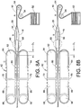
- a separator such as a knife cutter 58 ( Figures 7A and 8A ), or a blunt surface 58' ( Figures 7B and 8B ) is present on the guide pin 56. In the embodiment illustrated by Figures 7A and 8A the knife cutter 58 extends from the guide pin 56.
- the knife cutter 58 is used to cut the inflation edge 18 illustrated by Figure 1 , but could also be used to cut the perforated inflation edge 18 illustrated by Figure 2 .
- the cutter 58 slits the inflation edge 18 as the web moves through the machine 50 to provide inflation openings 59 (See Figure 9 ) into the pouches, while leaving the pouches otherwise imperforate. A variation of this would have the cutter 58 cutting either layer 14, 16, or both near the inflation edge 18.
- the guide pin 56 defines a separator in the form of the blunt surface 58' and the knife cutter is omitted.
- the blunt surface 58' is used to break the perforated inflation edge illustrated by Figure 2 .
- the blunt surface 58' breaks open the inflation edge 18 as the web moves through the machine to provide the inflation openings into the pouches 12.
- a blower 60 is positioned after the cutter 58 or blunt surface 58' in station B.
- the blower 60 inflates the web pouches as the web moves past the blower.
- the web pouches are opened and inflated at station B.
- the seal edges 38, 40 spread apart as indicated by arrows 61 ( Figures 7A , 7B and 9 ) as the web pouches are inflated.
- the frangible connections 29, 36 maintain successive pouches substantially aligned as the web is fed to the filling station B.
- the frangible connections are sufficiently weak that the connection between a pouch that has been opened for inflation and is being inflated at the fill station B and an adjacent, successive (or preceding) pouch will rupture as the pouch at the fill station is inflated.
- the spreading of the edges 38, 40 forms a row of inflated dunnage units in a ladder configuration and increases the volume of the air that can enter the pouches. The spreading also reduces the stresses imparted to the web adjacent the inflation side edge 18 where it is to be sealed.
- the inflation seal 42 is formed at station C by a sealing assembly 62 to complete each dunnage unit.
- the inflated volume of the pouches is maintained by continuing to blow air into the pouch until substantially the entire length of the inflation opening 59 is sealed.
- the blower 60 blows air into a pouch being sealed up to a location that is a short distance D 1 from closing position where the sealing assembly 62 pinches the top and bottom layers 14, 16 to maintain the inflated volume of the pouches.
- This distance D 1 is minimized to minimize the volume of air that escapes from the inflated pouch before the trailing transverse seal of the inflated pouch reaches the closing position.
- the distance D 1 may be 0.64 cm (0.250 inches) or less, to blow air into the inflation opening unit the trailing transverse seal is within 0.64 cm (0.250 inches) of the closing position.
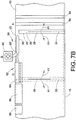
- the sealing assembly includes a pair of heated sealing elements 64, a pair of cooling elements 66, a pair of drive rollers 68, and a pair of drive belts 70.
- the pair of cooling elements is omitted.
- Each belt 70 is disposed around its respective heat sealing element 64, cooling element 66 (if included), and drive roller 68.
- Each belt 70 is driven by its respective drive roller 68.
- the belts 70 are in close proximity or engage one another, such that the belts 70 pull the web 10 through the heat sealing elements 64 and the cooling elements 66.
- the seal 42 is formed as the web 10 passes through first the heated sealing elements 64 and then a heat sink such as the cooling elements.
- One suitable heating element 64 includes heating wire 80 carried by an insulating block 82. Resistance of the heating wire 80 causes the heating wire 80 to heat up when voltage is applied.
- the cooling elements 66 cool the seal 42 as the web 10 is pulled between the cooling elements.
- One suitable cooling element is an aluminum (or other heatsink material) block that transfers heat away from the seal 42. Referring to Figure 9 , the spreading of the edges 38, 40 greatly reduces the stress imparted on the web material at or near the seal 42. As a result, a much more reliable seal 42 is formed.
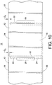
- Figures 10-12 show another embodiment of a web 10.
- the spaced apart lines of perforations 26 extending from the inflation edge 18, as shown in Figures 1 - 7B and 9 is replaced with a modified line of perforations 90.
- a starting point 89 of the line of perforations 90 begins a distance D 2 from the inflation edge 18 and extends away from and generally perpendicular to the inflation edge 18.
- a frangible connection 21' also shown in Figure 2A
- the distance D 2 is greater than the distance D 4 .
- the line of perforations 90 extends to a gap forming area 28 and an opposite edge line of perforations 24 extends to the opposite edge.
- the gap forming area 28 is not included and the line of perforations 90 extends all the way or nearly all the way to the opposite edge.
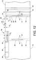
- the distance D 2 is selected to prevent the cutter ( Figure 12 ) from engaging the line of perforations in the exemplary embodiment. Although distance D 2 may vary based on the particular cutter implemented, in one embodiment, distance D 2 is approximately 0.64 to 0.95 cm (0.25 to 0.375 inch) in length.
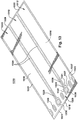
- Figure 11 illustrates a row of inflated dunnage units. The elimination of perforations extending to the inflation edge 18 does not make it substantially harder to separate adjacent dunnage units in the row 11 of dunnage units 12' in the exemplary embodiment. The dunnage units 12' can still be separated by inserting an object or objects, such as a hand or hands, into the gap 13 and pulling one dunnage unit 12' away from an adjacent dunnage unit 12'. When the dunnage units are pulled apart, the thin web of material between the starting point 89 and the inflation edge easily breaks.
- the process of forming perforations through the top and bottom layers of plastic 14, 16, as the web 10 is formed, may cause the top and bottom layers 14, 16 to be adhere or be held together at the line of a perforations.
- the cutter will engage each line of perforations. Engagement of the lines of perforations by the cutter may cause the web to bind, wrinkle, bunch up, or gather around the edge of the cutter until the cutter passes the line of perforations and begins cutting the web again.
- engagement of the line of perforations 90 with the cutter is eliminated by beginning the line of perforations 90 a distance D 2 away from the inflation edge18.
- the tip of a cutter 58 utilized in opening the inflation edge 18 is positioned a distance D 3 past the inflation edge 18 as the edge is opened.
- the distance D 2 that the line of perforations 90 is away from the inflation edge 18 is configured to be greater that the distance D 3 to which the tip of a cutter 58 is positioned past the inflation edge 18.
- the cutter 58 will not engage the lines of perforations.
- the cutter 58 or blunt surface 58' ( Figure 7B ) that opens the offset frangible connection 21' will not engage the lines of perforations 90. This eliminates the possibility that the cutter or blunt surface could engage the lines of perforations and cause the web to bunch up or gather around the cutter 58 or blunt surface 58' as the cutter 58 opens the inflation edge.
- Figures 13 and 14 illustrate another embodiment of a web 1310 of inflatable pouches 1312. Any of the features of the webs illustrated in Figures 1 , 2 , 4-6 , and 10-12 can be incorporated into the web 1310 or replace features of the web 1310 described below. Further, any of the features of the web 1310 can be incorporated into the webs illustrated in Figures 1 , 2 , 4-6 , and 10-12 or replace features of the webs described in Figures 1 , 2 , 4-6 , and 10-12 .
- the web 1310 includes a top elongated layer of plastic 1314 superposed onto a bottom layer of plastic 1316. The layers are connected together along spaced edges, referred to as the inflation edge or side 1318 and the opposite edge or side 1320.
- an optional frangible connection 1321 is spaced apart from the inflation edge 1318.
- the illustrated frangible connection 1321 is a line of perforations.
- the frangible connection 1321 is present in one of the superposed layers, at a location offset from the inflation edge 1318 by a distance. This distance may be between 0.19 and 0.64 cm (0.075 and 0.25 inches), in an exemplary embodiment between 0.24 and 0.40 cm (0.09375 and 0.15625 inches), for example 0.33 cm (0.13 inches).
- a plurality of seals 1322 join the top and bottom layers 1314, 1316 to define pouches 1312.
- the seals 1322 may take a wide variety of different configurations.
- the seals 1322 define an elongated tube having a length L 1 and a width W 1 (see Figure 14 ).
- the seals 1322 further define a mouth 1323 of the elongated tube having a width W 2 that is narrower than the width W 1 of the elongated tube.
- optional mouth dividing seals 1325 divide the mouth 1323 into multiple ports 1327 and reduce the area of the mouth through which air can pass. This reduction of the area through which air can pass, reduces the amount of an air which escapes as the pouch is sealed.
- the dividing seals 1325 can take any form and can define any number of inflation ports 1327.
- Spaced pairs of lines of perforations 1324, 1326 extend through the top and bottom layers.
- a gap forming area 1328 extends between each associated pair of lines of perforations 1324, 1326.
- the inflation side line of perforations 1326, the gap forming area 1328, and the opposite side line of perforations 1324 are arranged in an in-line, end to end configuration between adjacent pairs of the pouches 12.
- the gap forming area 1328 opens to form a gap 1313 when the pouches are inflated.
- at least one of the lines of perforations 1324, 1326 are significantly longer than the gap forming area 1328.
- the line of perforations 1324 and/or the line of perforations 1326 may be at least three times as long as the gap forming area 1328.
- a length L 2 of the line of perforations 1324 is three to ten times as long a length L 3 of the gap forming area and a length L 4 of the line of perforations 1326 is the same length or shorter than the length L 3 of the gap forming area 1328.
- the gap forming area 1328 may be positioned and sized to allow better inflation of the pouch 1312 and give the user a hole to start to tear with.
- a start or beginning 1329 of the gap forming area 1328 is aligned or substantially aligned with a transition 1331 of the tube from the mouth (having width W 2 ) to the elongated tube portion (having width W 1 ).
- the length L 3 of the gap forming area may be selected for the particular application of the pouches 1312. In one embodiment, the length L 3 of the gap forming area may be between 2.54 and 10.16 cm (one and four inches), for example the length L 3 may be about 4.57 cm (1.8 inches).
- a gap forming area 1328 denotes an area, preferably linear in shape, that will rupture or otherwise separate when exposed to a predetermined inflation force.
- the magnitude of the inflation force is less than the magnitude of the force needed to rupture or separate the spaced apart lines of perforations 1324.
- the gap forming area 1328 can take a variety of different forms, as discussed above. Any method that produces an area between the spaced apart lines of perforations 1324, 1326 that ruptures or otherwise separates at a force lower than a force needed t rupture or separate spaced lines of perforations 1324, 1326 may be employed to make the gap forming area 28.
- a pouch 1312 prior to conversion to a dunnage unit, is typically hermetically sealed on three sides, leaving the mouth 1323 open to allow for inflation. Once the pouch is inflated, the mouth 1323 is hermetically sealed and the dunnage unit 1312' is formed as described above.
- the gap forming area 1328 produces a gap 1313 between adjacent pouches upon inflation.
- the gap allows foreshortening of the connected pouch sides in the area of the mouth 1323 and thereby reduces the undesirable stresses that are introduced during inflation.
- the gap 1313 maintains the inflation opening substantially free of wrinkles as the inflation opening is sealed to convert the inflated pouches to a dunnage units.
- the illustrated web 1310 is constructed from a heat sealable plastic film, such as polyethylene.
- the web 1310 is designed to accommodate a process for inflating each pouch 1312 in the web to create a row or ladder 1311 of dunnage units 1312.
- the gap forming area 1328 creates a gap 1313 between dunnage units 1312, which facilitate a efficient and effective process for separating adjacent dunnage units 1312 in the row or ladder 1311.
- the gap forming area 1328 may be an easily breakable line of perforations, an elongated cut through both layers of material, or separated by light connections of plastic, also referred to as "ticks" as described above.
- Figures 15-17 illustrate a length of the web 1310 after it has been inflated and sealed to form dunnage units 1312'.
- An inflation seal 1342 seals the pouches 1312 shut.
- Each pair of adjacent dunnage units 1312' are connected together by the pair of spaced apart lines of perforations 1324, 1326.
- the spaced apart lines of perforations 1324, 1326 are spaced apart by the gap 1313.
- a single row 1311 of dunnage units 1312' can be graphically described as being in a "ladder" configuration. This configuration makes separating two adjacent dunnage units 1312' easy.
- a worker simply inserts an object or objects, such as a hand, hands, finger and/or fingers, into the gap 1313 and pulls one dunnage unit 1312' away from the other dunnage unit 1312'.
- a mechanical system can be used to separate dunnage units 1312'.
- a machine can be configured to insert an object between adjacent dunnage units 1312' and apply a force to separate the units.
- the existence of the gap 1313 also results in reduced stresses in the area of the inflation seal 1324, 1326 at the time of sealing and accommodates increased inflation volume of the dunnage units 1312'.
- the web 1310 can be converted to dunnage units 1312' using the machine 50 and process schematically illustrated by Figures 7A , 7B , 8A, 8B and 9 and as described with respect to the webs 10, 10', 10" and 10""". However, the web 1310 can be converted to dunnage units 1312 in any manner. When the web 1310 includes the line of perforations 1321, this line of perforations 1321 will be broken as the machine 50 converts the web 1310 to dunnage units 1312'.
Claims (8)
- Bande (1310) pour former des unités de garnissage (1312'), comprenant:une première couche allongée (1314);une seconde couche allongée (1316) superposée sur la première couche allongée (1314);une pluralité de joints (1322) qui joignent hermétiquement la première couche allongée (1314) à la seconde couche allongée (1316) de manière à former une pluralité de poches gonflables (1312) et un canal de gonflage qui se trouve en communication fluidique avec des poches (1312) et qui est disposé à l'extérieur desdites poches (1312);dans laquelle les poches (1312) comprennent une partie de bouche (1323) et une partie de tube allongé, et dans lequel une largeur de la partie de tube allongé est plus grande qu'une largeur de la partie de bouche (1323);une ligne latérale de perforations de gonflage (1326) à travers les première et seconde couches, entre au moins une paire de poches adjacentes (1312);une région de formation d'espace (1328) définie dans les première et seconde couches, entre ladite au moins une paire de poches adjacentes (1312);une ligne latérale opposée de perforations (1324) à travers les première et seconde couches, entre ladite au moins une paire de poches adjacentes (1312);dans laquelle la ligne latérale de perforations de gonflage (1326), la région de formation d'espace (1328) et la ligne latérale opposée de perforations (1324) sont disposées en ligne,caractérisée en ce que la ligne latérale de perforations de gonflage (1326) présente une longueur qui s'étend à partir du canal de gonflage jusqu'à la région de formation d'espace (1328), la région de formation d'espace (1328) présente une longueur qui s'étend à partir de la ligne latérale de perforations de gonflage (1326) jusqu'à la ligne latérale opposée de perforations (1324); etune longueur de la ligne latérale opposée de perforations (1324) est au moins trois fois aussi longue que la longueur de la région de formation d'espace (1328), et un début (1329) de la région de formation d'espace (1328) est aligné avec une transition (1331) entre la largeur de la partie de bouche (1323) et la largeur de la partie de tube allongé de la poche (1312).
- Bande (1310) selon la revendication 1, dans laquelle la longueur de la ligne latérale de perforations de gonflage (1326) est inférieure ou égale à la longueur de la région de formation d'espace (1328).
- Bande (1310) selon la revendication 1, dans laquelle la longueur de la ligne latérale opposée de perforations (1324) est entre trois fois et dix fois aussi longue que la longueur de la région de formation d'espace (1328).
- Bande (1310) selon la revendication 1, dans laquelle la bouche est divisée en de multiples ports (1327).
- Bande (1310) selon la revendication 1, dans laquelle la région de formation d'espace (1328) comprend une entaille.
- Bande (1310) selon la revendication 1, dans laquelle la région de formation d'espace (1328) comprend une ligne de perforations qui est plus faible que la ligne latérale de perforations de gonflage (1326) et que la ligne latérale opposée de perforations (1324).
- Bande (1310) selon la revendication 1, dans laquelle la région de formation d'espace (1328) comprend des entailles et des encoches.
- Bande (1310) selon la revendication 1, dans laquelle la longueur de la ligne latérale de perforations de gonflage (1326) est inférieure ou égale à la longueur de la région de formation d'espace (1328).
Priority Applications (1)
| Application Number | Priority Date | Filing Date | Title |
|---|---|---|---|
| PL09789543T PL2401142T3 (pl) | 2009-02-27 | 2009-03-26 | Wstęga i sposób wytwarzania modułów wypełnionych płynem |
Applications Claiming Priority (2)
| Application Number | Priority Date | Filing Date | Title |
|---|---|---|---|
| US12/394,781 US9205622B2 (en) | 2009-02-27 | 2009-02-27 | Web and method for making fluid filled units |
| PCT/US2009/038344 WO2010098777A1 (fr) | 2009-02-27 | 2009-03-26 | Bande et procédé pour réaliser des unités remplies de fluide |
Publications (2)
| Publication Number | Publication Date |
|---|---|
| EP2401142A1 EP2401142A1 (fr) | 2012-01-04 |
| EP2401142B1 true EP2401142B1 (fr) | 2017-01-11 |
Family
ID=41198585
Family Applications (1)
| Application Number | Title | Priority Date | Filing Date |
|---|---|---|---|
| EP09789543.7A Active EP2401142B1 (fr) | 2009-02-27 | 2009-03-26 | Bande pour réaliser des unités remplies de fluide |
Country Status (7)
| Country | Link |
|---|---|
| US (2) | US9205622B2 (fr) |
| EP (1) | EP2401142B1 (fr) |
| CA (1) | CA2753470C (fr) |
| ES (1) | ES2621272T3 (fr) |
| HU (1) | HUE032508T2 (fr) |
| PL (1) | PL2401142T3 (fr) |
| WO (1) | WO2010098777A1 (fr) |
Families Citing this family (15)
| Publication number | Priority date | Publication date | Assignee | Title |
|---|---|---|---|---|
| US7757459B2 (en) | 2004-06-01 | 2010-07-20 | Automated Packaging Systems, Inc. | Web and method for making fluid filled units |
| US7897219B2 (en) * | 2004-06-01 | 2011-03-01 | Automated Packaging Systems, Inc. | Web and method for making fluid filled units |
| US7862870B2 (en) * | 2005-05-06 | 2011-01-04 | Pregis Innovative Packaging, Inc. | Films for inflatable cushions |
| US8354150B2 (en) | 2007-10-31 | 2013-01-15 | Automated Packaging Systems, Inc. | Web and method for making fluid filled units |
| US9205622B2 (en) * | 2009-02-27 | 2015-12-08 | Automated Packaging Systems, Inc. | Web and method for making fluid filled units |
| US9623622B2 (en) | 2010-02-24 | 2017-04-18 | Michael Baines | Packaging materials and methods |
| US20140130461A1 (en) * | 2011-06-22 | 2014-05-15 | Pronova Ab | Device for producing shock-absorbing inflatable package and method for filling it |
| MX353115B (es) | 2011-07-07 | 2017-12-20 | Automated Packaging Systems Inc | Máquina para inflar cojines de aire. |
| MX2015011259A (es) | 2013-03-15 | 2016-02-03 | Automated Packaging Syst Inc | Empaque inflable sobre demanda. |
| JP2016532611A (ja) | 2013-09-10 | 2016-10-20 | オートメイテッド パッケージング システムズ, インコーポレイテッド | 流体充填ユニットを作成するためのウェブ |
| AU2014352854B2 (en) | 2013-11-21 | 2019-02-28 | Automated Packaging Systems, Inc. | Air cushion inflation machine |
| WO2015160862A1 (fr) | 2014-04-14 | 2015-10-22 | Pregis Innovative Packaging Llc | Structure flexible munie d'une conduite de gonflage sans perforations |
| US20160137355A1 (en) * | 2014-11-10 | 2016-05-19 | Pregis Innovative Packaging Llc | Inflatable produce packaging |
| US11542082B2 (en) | 2018-08-14 | 2023-01-03 | Pregis Innovative Packaging Llc | Inflatable packaging with variable tie tear initiation features |
| WO2020072727A1 (fr) | 2018-10-04 | 2020-04-09 | Automated Packaging Systems, Llc | Machine de gonflage de coussin d'air |
Family Cites Families (204)
| Publication number | Priority date | Publication date | Assignee | Title |
|---|---|---|---|---|
| US2153214A (en) | 1936-10-03 | 1939-04-04 | Warner Bros | Pressure pad |
| US2379935A (en) | 1941-10-08 | 1945-07-10 | Mayer & Co Inc O | Packaging method |
| US3033257A (en) | 1957-08-21 | 1962-05-08 | H G Weber And Company Inc | Bag forming tube and method of forming and accumulating the same |
| NL281183A (fr) | 1962-07-19 | |||
| US3254828A (en) | 1963-12-18 | 1966-06-07 | Automated Packaging Corp | Flexible container strips |
| US3298156A (en) | 1964-01-07 | 1967-01-17 | Automated Packaging Corp | Method and apparatus for packaging |
| US3254820A (en) | 1964-06-15 | 1966-06-07 | Du Pont | Shock absorbing system for yarn delivery apparatus |
| US3389534A (en) | 1965-09-16 | 1968-06-25 | John M. Pendleton | Machine for making cushioning packaging material or the like |
| US3414140A (en) | 1966-08-01 | 1968-12-03 | Interlake Steel Corp | Dunnage |
| US3358823A (en) | 1967-01-16 | 1967-12-19 | Allen D Paxton | Gusset bottom bags in roll form and method of making same |
| US3477196A (en) | 1967-04-27 | 1969-11-11 | Automated Packaging Corp | Mechanism for automatically feeding,loading,and sealing bags |
| US3462027A (en) | 1967-08-14 | 1969-08-19 | Edmund C Puckhaber | Dunnage device |
| US3456867A (en) | 1967-11-03 | 1969-07-22 | Dow Chemical Co | Bag assemblage |
| US3575757A (en) | 1967-12-08 | 1971-04-20 | Reinforced Air Corp | Process for making inflated articles |
| US3559874A (en) | 1968-05-08 | 1971-02-02 | Dow Chemical Co | Series bag construction |
| US3616155A (en) | 1968-06-26 | 1971-10-26 | Sealed Air Corp | Cellular laminate made from two thermoplastic sheets having polyvinylidene chloride coatings on facing sides of the sheets |
| US3523055A (en) | 1968-08-19 | 1970-08-04 | Jerome H Lemelson | Composite material,apparatus and method for producing same |
| US3577305A (en) | 1968-08-22 | 1971-05-04 | Theodore G Hines | Thermal and air shock insulating structure |
| US3660189A (en) | 1969-04-28 | 1972-05-02 | Constantine T Troy | Closed cell structure and methods and apparatus for its manufacture |
| US3575781A (en) | 1969-05-16 | 1971-04-20 | Stauffer Hoechst Polymer Corp | Plastic film wrapping material |
| BE754395A (fr) | 1969-08-04 | 1971-02-04 | Basf Ag | Procede et dispositif pour fabriquer ou fermer des sacs par soudage de portions de gaine en matiere thermoplastique |
| US3650877A (en) | 1969-10-06 | 1972-03-21 | Arpax Co | Cushioning dunnage product |
| US3585858A (en) * | 1969-11-28 | 1971-06-22 | Avco Corp | Signal error compensated fluidic oscillator temperature sensors |
| US3667593A (en) | 1970-03-30 | 1972-06-06 | John M Pendleton | Flowable dunnage apparatus and method of packaging with flowable and compliable inflated dunnage material |
| US3618286A (en) | 1970-06-08 | 1971-11-09 | Hercules Membrino | Bag filling sealing and separating system |
| US3837990A (en) | 1970-06-19 | 1974-09-24 | Connell R Mc | Reinforced cushioning material |
| US3802974A (en) | 1970-12-01 | 1974-04-09 | L Emmel | Method and apparatus for insulating electrically conductive elements |
| US3730240A (en) | 1971-03-16 | 1973-05-01 | Metatronics Manuf Corp | Inflatable insulation for packaging |
| US3699746A (en) | 1971-04-09 | 1972-10-24 | Basic Packaging Systems Inc | Apparatus for filling a chain of connected bag elements |
| US3744211A (en) | 1971-04-09 | 1973-07-10 | Dow Chemical Co | Automatic bag filling method |
| US3837991A (en) | 1971-05-03 | 1974-09-24 | Kimberly Clark Co | Plastic cushioning reinforced material |
| US3791573A (en) | 1971-11-15 | 1974-02-12 | Basic Packaging Sys Inc | Bag construction |
| US3795163A (en) | 1971-12-16 | 1974-03-05 | Dow Chemical Co | Method of selectively cutting and perforating superposed panels of material |
| US3817803A (en) | 1972-06-19 | 1974-06-18 | Fmc Corp | Method of making a cellular cushioning structure |
| US3941306A (en) | 1972-06-23 | 1976-03-02 | Weikert Roy J | System of interconnected, sealed and unsealed bags |
| US3813845A (en) | 1972-06-23 | 1974-06-04 | Gen Films Inc | Filling and sealing system |
| US4014154A (en) | 1973-02-28 | 1977-03-29 | Automated Packaging Systems, Inc. | Packaging method and apparatus |
| US3808981A (en) | 1973-03-02 | 1974-05-07 | Interlake Inc | Disposable inflatable dunnage |
| US4021283A (en) | 1974-01-24 | 1977-05-03 | Weikert Roy J | Method of making aseptic packaging |
| US3938298A (en) | 1974-05-20 | 1976-02-17 | Minnesota Mining And Manufacturing Company | System for inflation and sealing of air cushions |
| US3939995A (en) | 1974-11-01 | 1976-02-24 | International Paper Company | Valve placement in a multi-ply, inflatable bag |
| US4017351A (en) | 1975-12-24 | 1977-04-12 | Minnesota Mining And Manufacturing Company | System and device for inflating and sealing air inflated cushioning material |
| US4169002A (en) | 1975-12-24 | 1979-09-25 | Minnesota Mining And Manufacturing Company | Method for forming air inflated cushioning material |
| US4096306A (en) | 1975-12-24 | 1978-06-20 | Minnesota Mining And Manufacturing Company | Strip material used in forming air inflated cushioning material |
| US4044693A (en) | 1976-03-12 | 1977-08-30 | Guardpack, Incorporated | Inflatable dunnage with tie-downs |
| US4040526A (en) | 1976-03-26 | 1977-08-09 | International Paper Company | Dunnage bag |
| US4076872A (en) | 1977-03-16 | 1978-02-28 | Stephen Lewicki | Inflatable cellular assemblies of plastic material |
| US4146069A (en) | 1977-07-29 | 1979-03-27 | Signode Corporation | Apparatus for rapidly inflating and pressurizing a dunnage bag |
| US4102364A (en) | 1977-07-29 | 1978-07-25 | Signode Corporation | Method of dunnage bag inflation |
| US4103471A (en) | 1977-09-01 | 1978-08-01 | International Paper Company | Atmosphere exchanging and bag sealing machine and method |
| DE2748615A1 (de) * | 1977-10-29 | 1979-05-03 | Richard Steimel | Verfahren und vorrichtung zum entoelen, rommeln, waschen und trocknen insbesondere von gegenstaenden mit sackloechern |
| US4201029A (en) | 1978-08-14 | 1980-05-06 | Automated Packaging Systems, Inc. | Method and apparatus for packaging |
| US4245796A (en) | 1979-06-15 | 1981-01-20 | Chromalloy American Corporation | System for handling flexible sheet rolls |
| US4314865A (en) | 1979-09-14 | 1982-02-09 | Ranpak Corp. | Method of making cushioning dunnage |
| US4306656A (en) | 1980-02-19 | 1981-12-22 | Dahlem A Richard | Medical pouches and a method of manufacturing such pouches |
| US4380484A (en) | 1981-02-20 | 1983-04-19 | William C. Heller, Jr. | Inductively heated tooling and method for working plastic members |
| US4354004A (en) | 1981-09-28 | 1982-10-12 | Shell Oil Company | Film compositions from olefin polymer blends |
| US4847126A (en) | 1982-07-01 | 1989-07-11 | Hiroshi Yamashiro | Elongated plastic material |
| CA1188557A (fr) | 1982-10-04 | 1985-06-11 | Roderick A. Bolton | Methode de production de sacs enchaines de longueur delimitee par des perforations |
| US4545180A (en) | 1982-12-16 | 1985-10-08 | Mpr Corporation | Method and apparatus for making and filling packets with a product |
| US4631901A (en) | 1982-12-16 | 1986-12-30 | Mpr Corporation | Apparatus and method for packaging a product in individual packets |
| JPS60134874A (ja) | 1983-11-11 | 1985-07-18 | オリヒロ株式会社 | 緩衝材の製造方法ならびに製造装置 |
| US4518654A (en) | 1983-12-23 | 1985-05-21 | Mobil Oil Corporation | One-sided cling stretch wrap |
| IT1176417B (it) | 1984-07-18 | 1987-08-18 | Vipa Studio Progettazione Rapp | Apparecchiatura per l'accatastamento di elementi lastriformi in genere quali fogli,pelli,lastre e simili |
| US4597244A (en) | 1984-07-27 | 1986-07-01 | M & D Balloons, Inc. | Method for forming an inflated wrapping |
| US4576669A (en) | 1984-11-09 | 1986-03-18 | Caputo Garry L | "On demand" apparatus and method for producing air-cushioning product |
| US4676376A (en) | 1985-10-04 | 1987-06-30 | Petoskey Plastics, Inc. | Temporary protective seat cover |
| US4616472A (en) | 1985-10-10 | 1986-10-14 | W. R. Grace & Co., Cryovac Div. | Method and apparatus for loading side-seal bags |
| US4619635A (en) | 1985-11-04 | 1986-10-28 | Ranpak Corp. | Automatic feed circuit for dunnage converter |
| ATE67977T1 (de) | 1985-11-08 | 1991-10-15 | Minigrip Europe Gmbh | Wiederverschliessbarer flexibler behaelter. |
| US4901506A (en) | 1987-03-30 | 1990-02-20 | Automated Packaging Systems, Inc. | Heat seal temperature control |
| US5188691A (en) | 1987-07-27 | 1993-02-23 | Caputo Gary L | Apparatus and method for producing air cushion product |
| US4918904A (en) | 1987-08-25 | 1990-04-24 | Pharo Daniel A | Method for forming clam-like packaging system |
| US4874093A (en) | 1987-08-25 | 1989-10-17 | Pharo Daniel A | Clam-like packaging system |
| US4793123A (en) | 1987-11-16 | 1988-12-27 | Pharo Daniel A | Rolled-up packaging system and method |
| DE3806271A1 (de) | 1988-02-27 | 1989-09-07 | Basf Ag | Thermoplastische formmassen auf der basis von polyamiden und ethylencopolymerisaten |
| CA1328432C (fr) | 1988-05-13 | 1994-04-12 | Lourence Cornelius Johannes Greyvenstein | Materiau perfore et lamine en continu |
| US4981374A (en) | 1988-09-30 | 1991-01-01 | Rapak, Inc. | Plastic bags carried in a continuous web |
| US4904092A (en) | 1988-10-19 | 1990-02-27 | Mobil Oil Corporation | Roll of thermoplastic bags |
| US4931033A (en) | 1989-02-01 | 1990-06-05 | Equitable Bag Co., Inc. | Plastic bag construction |
| US4922687A (en) | 1989-04-24 | 1990-05-08 | Hewlett-Packard Company | Automated packaging loose fill system |
| DE3922802A1 (de) | 1989-07-11 | 1991-01-24 | Becker Rolf | Aufblasbarer folienbeutel, insbesondere fuer verpackungszwecke und verfahren zu dessen herstellung |
| US4945714A (en) | 1989-11-14 | 1990-08-07 | Package Machinery Company, Bodolay/Pratt Division | Form, fill, seal and separate packaging machine for reclosable containers |
| US5070675A (en) | 1990-01-29 | 1991-12-10 | Jen-Wei Lin | Inflating and heat sealing apparatus for plastic packing bags |
| US5141494A (en) | 1990-02-15 | 1992-08-25 | Danforth Biomedical, Inc. | Variable wire diameter angioplasty dilatation balloon catheter |
| US5064408A (en) | 1990-08-22 | 1991-11-12 | Bridgeman Daniel N P | Method and apparatus for producing a plurality of continuous bags |
| US5187917A (en) | 1990-10-29 | 1993-02-23 | Cvp Systems, Inc. | Automatic packaging apparatus and method and flexible pouch therefor |
| ATE134567T1 (de) | 1990-11-28 | 1996-03-15 | Crescent Holding | Verfahren und vorrichtung zur anwendung von in kontinuierlicher bandform an füllstationen zugeführten und heisssiegelbaren zwei an zwei gegenüberliegenden behältern und die dabei erzeugten packungen |
| US5094657A (en) | 1990-11-29 | 1992-03-10 | Cloud Corporation | Method and apparatus for continuously forming and sealing low density polyethylene bags at high speed |
| US5752666A (en) | 1991-02-07 | 1998-05-19 | Simhaee; Ebrahim | Plastic bag roll |
| US5383837A (en) | 1991-04-05 | 1995-01-24 | Patriot Packaging Corporation | Method and apparatus for making improved dunnage |
| US5181614A (en) | 1991-04-05 | 1993-01-26 | Ridley Watts | Coil dunnage and package using same |
| US5257492A (en) | 1991-04-05 | 1993-11-02 | Patriot Packaging Corporation | Dunnage, method and apparatus for making, and package using same |
| US5117608A (en) | 1991-04-10 | 1992-06-02 | R. A. Jones & Co. Inc. | Pouch profile detector |
| ES2075405T3 (es) | 1991-05-03 | 1995-10-01 | Michel Chappuis | Elemento acolchado para embalar objetos y dispositivo para la fabricacion de un elemento acolchado. |
| US5203761A (en) | 1991-06-17 | 1993-04-20 | Sealed Air Corporation | Apparatus for fabricating dunnage material from continuous web material |
| US5216868A (en) | 1992-01-28 | 1993-06-08 | Andrew K. Cooper | Packaging product and machine for making same |
| US5272856A (en) | 1992-07-30 | 1993-12-28 | Air Packaging Technologies, Inc. | Packaging device that is flexible, inflatable and reusable and shipping method using the device |
| US5394676A (en) | 1992-09-30 | 1995-03-07 | Automated Packaging Systems, Inc. | Packaging machine and method |
| US5289671A (en) | 1992-09-30 | 1994-03-01 | Automated Packaging Systems, Inc. | Packaging machine and method |
| US5470300A (en) | 1992-09-09 | 1995-11-28 | Ro-An Industries Corporation | Web registration system and method |
| US5307969A (en) | 1992-11-27 | 1994-05-03 | Menendez Vincent M | Bag dispensing apparatus |
| SE501545C2 (sv) | 1993-05-05 | 1995-03-13 | Jan Jostler | Bana för förpackningsämnen samt sätt att öppna och fylla förpackningsfickor i banan |
| US5454642A (en) | 1993-07-16 | 1995-10-03 | Novus Packaging Corporation | Inflatable flat bag packaging cushion and methods of operating and making the same |
| JPH07165265A (ja) * | 1993-10-28 | 1995-06-27 | K Jasai Z | 緩衝保護装置 |
| US5427294A (en) | 1993-11-12 | 1995-06-27 | Reynolds Consumer Products Inc. | Method and apparatus for breaking film perforations |
| US5824392A (en) | 1994-03-24 | 1998-10-20 | Idemitsu Petrochemical Co., Ltd. | Method of producing an air cushion and an apparatus for the same |
| WO1996003603A1 (fr) | 1994-07-21 | 1996-02-08 | Nicholas Paolo De Luca | Ensemble valve a effet de battement pour emballage gonflable |
| USRE36759E (en) | 1994-10-04 | 2000-07-04 | Automated Packaging Systems, Inc. | Inflated dunnage and method for its production |
| US5552003A (en) | 1994-10-04 | 1996-09-03 | Hoover; Gregory A. | Method for producing inflated dunnage |
| US5693163A (en) | 1994-10-04 | 1997-12-02 | Hoover; Gregory A. | Inflated dunnage and method for its production |
| DE4440660C2 (de) | 1994-11-14 | 1998-12-03 | Windmoeller & Hoelscher | Trenneinrichtung zum Abtrennen perforierter Schlauchabschnitte |
| US5651237A (en) | 1995-06-06 | 1997-07-29 | Novus Packaging Corporation | Apparatus and methodology for packaging items incorporating an inflatable packaging system |
| US5699653A (en) | 1995-11-06 | 1997-12-23 | Cloud Corporation | Pouch machine for making maximum volume pouch |
| US20010014980A1 (en) | 1996-06-11 | 2001-08-23 | Melanie Patterson | Disposable paper bib |
| US6151716A (en) | 1996-06-11 | 2000-11-28 | Patterson; Melanie S. | Disposable paper bib |
| US5810200A (en) | 1996-08-09 | 1998-09-22 | The Procter & Gamble Company | Pop-up tissue package |
| US5996319A (en) | 1996-08-16 | 1999-12-07 | Automated Packaging Systems, Inc. | Packaging machine, material and method |
| US5743070A (en) | 1996-08-16 | 1998-04-28 | Automated Packaging Systems, Inc. | Packaging machine, material and method |
| EP0825115B1 (fr) | 1996-08-16 | 1999-10-20 | Automated Packaging Systems, Inc. | Procédé et machine de scellage |
| US5722218A (en) | 1996-08-16 | 1998-03-03 | Automated Packaging Systems, Inc. | Plastic transport system |
| US5904657A (en) * | 1997-02-26 | 1999-05-18 | Unsworth; John D. | System for guiding devices in body lumens |
| AU7116898A (en) | 1997-04-11 | 1998-11-11 | Ebrahim Simhaee | Continuous strip of plastic bags |
| US6609644B1 (en) | 1997-09-26 | 2003-08-26 | Instant Technologies, Inc. | Method of dispensing perforated tickets |
| US6228454B1 (en) | 1998-02-02 | 2001-05-08 | Fort James Corporation | Sheet material having weakness zones and a system for dispensing the material |
| DE19808881A1 (de) * | 1998-03-03 | 1999-09-09 | Focke & Co | Verfahren und Vorrichtung zum Herstellen von Packungen mit verleimten Faltlappen |
| US6015047A (en) | 1998-04-08 | 2000-01-18 | Greenland; Steven J. | Inflatable package cushioning and method of using same |
| US7665394B2 (en) | 1998-04-14 | 2010-02-23 | Gtech Corporation | Ticket dispensing modules and method |
| US6015357A (en) | 1998-12-02 | 2000-01-18 | Rizza; Joseph D. | Broadhead for use as both an expandable blade head and a fixed blade head |
| US6116000A (en) | 1998-12-08 | 2000-09-12 | Novus Packaging Corporation | Method of and apparatus for manufacturing air-filled sheet plastic and the like |
| US6519916B1 (en) | 1998-12-21 | 2003-02-18 | Free-Flow Packaging International, Inc. | System and method for conveying air-filled packing cushions |
| US7536837B2 (en) | 1999-03-09 | 2009-05-26 | Free-Flow Packaging International, Inc. | Apparatus for inflating and sealing pillows in packaging cushions |
| US6209286B1 (en) | 1999-03-09 | 2001-04-03 | Novus Packaging Corporation | Machine and method for manufacturing a continuous production of pneumatically filled inflatable packaging pillows |
| US6423166B1 (en) | 1999-04-22 | 2002-07-23 | Ebrahim Simhaee | Method of making collapsed air cell dunnage suitable for inflation |
| US6460313B1 (en) | 1999-05-24 | 2002-10-08 | Andrew Cooper | Packaging filler product and machine for producing same |
| US6751926B1 (en) | 1999-05-11 | 2004-06-22 | Andrew Cooper | Packaging filler product and machine for producing same |
| US6948296B1 (en) | 1999-05-20 | 2005-09-27 | Automated Packaging Systems, Inc. | Dunnage material and process |
| US6199349B1 (en) | 1999-05-20 | 2001-03-13 | Automated Packaging Systems, Inc. | Dunnage material and process |
| US6527147B2 (en) | 2000-12-12 | 2003-03-04 | Automated Packaging Systems, Inc. | Apparatus and process for dispensing dunnage |
| US20010000719A1 (en) | 1999-05-20 | 2001-05-03 | Automated Packaging Systems, Inc. | Dunnage material and process |
| DE69919231T2 (de) | 1999-06-22 | 2005-08-11 | Soudan Patrimonium & Consulting N.V. | Vorrichtung und verfahren zum kontinuierlichen herstellen von schaumkissen für verpackungszwecke |
| US6582800B2 (en) * | 2000-01-20 | 2003-06-24 | Free-Flow Packaging International, Inc. | Method for making pneumatically filled packing cushions |
| EP1280651B2 (fr) | 2000-05-08 | 2010-02-24 | Free-Flow Packaging International, Inc. | Dispositif de fabrication de coussins remplis de matiere |
| CA2348181A1 (fr) * | 2000-05-18 | 2001-11-18 | Automated Packaging Systems, Inc. | Materiau d'emballage protecteur et et processus connexe |
| US6488222B1 (en) | 2000-08-18 | 2002-12-03 | Larry G. West | Bag dispensing system and C-fold bag used therewith |
| US6952910B1 (en) | 2000-09-27 | 2005-10-11 | Loersch Johannes | Gas filled bodies |
| AU772208B2 (en) | 2000-10-06 | 2004-04-22 | Northfield Corporation | Web Burster/inserter |
| ATE335607T1 (de) | 2000-11-08 | 2006-09-15 | Sharp Packaging Systems Llc | Zuführ- und ladevorrichtung für ein kontinuierliches beutelband mit intergrierter druckanordnung |
| US6696127B1 (en) | 2000-11-13 | 2004-02-24 | Translucent Technologies Llc | Differential perforation pattern for dispensing print media |
| USD490711S1 (en) | 2000-11-21 | 2004-06-01 | Free-Flow Packaging International, Inc. | Inflatable packing material |
| US6410119B1 (en) | 2000-11-21 | 2002-06-25 | Free-Flow Packaging International, Inc. | Inflatable, cushioning, bubble wrap product having multiple, interconnected, bubble structures |
| USD512311S1 (en) | 2000-11-21 | 2005-12-06 | Free-Flow Packaging International, Inc. | Inflatable packing material |
| US6550229B2 (en) | 2001-01-12 | 2003-04-22 | Sealed Air Corporation (Us) | Device for sealing two plies of film together, particularly for enclosing a foamable composition in a flexible container |
| US6651406B2 (en) | 2001-02-13 | 2003-11-25 | Sealed Air Corporation (Us) | Apparatus and method for forming inflated containers |
| US6367975B1 (en) | 2001-05-24 | 2002-04-09 | Automated Packaging Systems, Inc. | Packaging web and process |
| US6635145B2 (en) | 2001-06-11 | 2003-10-21 | Andrew Cooper | Packaging filler product |
| US6543201B2 (en) | 2001-09-07 | 2003-04-08 | Automated Packaging Systems, Inc. | Individual package bagger and process |
| DE60209259T2 (de) | 2001-11-16 | 2006-11-02 | 3M Innovative Properties Co., St. Paul | Aufblasbares verpackungsschutzsystem mit niedrigem profil |
| DE10160408C2 (de) | 2001-12-10 | 2003-11-06 | Johannes Loersch | Gasgefüllte Füllkörper |
| GB2384459A (en) | 2002-01-25 | 2003-07-30 | John Stuart Greenwood | Manufacture of air cushions from tubing with a gas injector continuously within the tubing |
| WO2003104103A1 (fr) | 2002-06-05 | 2003-12-18 | Nova-Tek Technologies Ltd. | Matiere de rembourrage cellulaire gonflable presentant une configuration de type brique |
| US20040000581A1 (en) | 2002-06-20 | 2004-01-01 | Sealed Air Corporation (Us) | Polypropylene/cushioned envelope |
| US6871755B2 (en) | 2002-08-29 | 2005-03-29 | Schafer Systems Inc. | Ticket counting dispenser |
| USD480971S1 (en) | 2002-09-17 | 2003-10-21 | Free-Flow Packaging International, Inc. | Inflatable packing material |
| USD480646S1 (en) | 2002-09-17 | 2003-10-14 | Free-Flow Packaging International, Inc. | Inflatable packing material |
| US6955846B2 (en) | 2003-04-08 | 2005-10-18 | Automated Packaging Systems | Web for fluid filled unit information |
| US6889739B2 (en) | 2003-04-08 | 2005-05-10 | Automated Packaging Systems, Inc. | Fluid filled unit formation machine and process |
| US7331542B2 (en) | 2003-05-09 | 2008-02-19 | Intellipack | Film unwind system with hinged spindle and electronic control of web tension |
| US8277910B2 (en) | 2003-06-28 | 2012-10-02 | Air-Paq, Inc. | Structure of fluid container and method and apparatus for producing the fluid container |
| JP4272941B2 (ja) | 2003-07-16 | 2009-06-03 | 株式会社柏原製袋 | 空気封入緩衝材及びその製造方法 |
| US7467738B2 (en) | 2003-11-13 | 2008-12-23 | Gtech Corporation | Lottery ticket dispenser and ticket bin |
| US20050132672A1 (en) | 2003-12-17 | 2005-06-23 | Hershey Lerner | Packaging machine and process |
| US7757459B2 (en) | 2004-06-01 | 2010-07-20 | Automated Packaging Systems, Inc. | Web and method for making fluid filled units |
| US7571584B2 (en) | 2004-06-01 | 2009-08-11 | Automated Packaging Systems, Inc. | Web and method for making fluid filled units |
| US7897219B2 (en) * | 2004-06-01 | 2011-03-01 | Automated Packaging Systems, Inc. | Web and method for making fluid filled units |
| US7059794B2 (en) | 2004-06-28 | 2006-06-13 | Transact Technologies Incorporated | Methods and apparatus for bursting perforated paper stock |
| US7578333B2 (en) | 2004-07-20 | 2009-08-25 | Pregis Corporation | Machine and methods for the manufacture of air-filled cushions |
| US8020358B2 (en) | 2004-11-02 | 2011-09-20 | Sealed Air Corporation (Us) | Apparatus and method for forming inflated containers |
| US7165375B2 (en) | 2005-02-05 | 2007-01-23 | Sealed Air Corporation (Us) | Inflation device for forming inflated containers |
| US20060218879A1 (en) | 2005-03-31 | 2006-10-05 | Sealed Air Corporation (Us) | Apparatus for forming inflated packaging cushions |
| US20090293427A1 (en) | 2005-08-01 | 2009-12-03 | Automated Packaging Systems, Inc. | Web and method for making fluid filled units |
| US7533772B2 (en) | 2005-10-20 | 2009-05-19 | Air- Paq, Inc. | Structure of air-packing device |
| US20070100076A1 (en) | 2005-10-28 | 2007-05-03 | Hayes Richard A | High modulus ionomers for packaging |
| US7607911B2 (en) | 2006-04-26 | 2009-10-27 | Sealed Air Corporation (Us) | Method and apparatus for making foam-in-place cushions with selective distribution of foam |
| US7513090B2 (en) | 2006-07-11 | 2009-04-07 | Automated Packaging Systems, Inc. | Apparatus and method for making fluid filled units |
| WO2008036641A2 (fr) | 2006-09-20 | 2008-03-27 | Pregis Innovative Packaging Inc. | Dispositif de gonflage et de fermeture hermétique pour coussins pneumatiques gonflables |
| US7540125B2 (en) | 2007-03-26 | 2009-06-02 | Northfield Corporation | Bursting apparatus and method |
| WO2009036237A1 (fr) | 2007-09-12 | 2009-03-19 | Automated Packaging Systems, Inc. | Machine d'emballage |
| USD599118S1 (en) | 2007-10-10 | 2009-09-01 | Free-Flow Packaging International, Inc. | Inflatable packing material |
| US8354150B2 (en) | 2007-10-31 | 2013-01-15 | Automated Packaging Systems, Inc. | Web and method for making fluid filled units |
| US7603830B2 (en) | 2008-01-28 | 2009-10-20 | Carol Joyce Witt | Apparatus for automatic belt pressure adjustment for coupon separation |
| IT1390687B1 (it) | 2008-07-11 | 2011-09-13 | Fill Teck S R L | Macchina per la produzione di materiale per imballaggio sotto forma di cuscini di aria, o altro gas, e relativo metodo |
| USD596031S1 (en) | 2008-10-03 | 2009-07-14 | Automated Packaging Systems, Inc. | Inflatable packing material |
| US7950433B2 (en) | 2009-02-12 | 2011-05-31 | Sealed Air Corporation (Us) | Machine for inflating and sealing an inflatable web |
| US9205622B2 (en) | 2009-02-27 | 2015-12-08 | Automated Packaging Systems, Inc. | Web and method for making fluid filled units |
| USD603705S1 (en) | 2009-02-27 | 2009-11-10 | Automated Packaging Systems, Inc. | Inflatable packing material |
| JP2010247900A (ja) | 2009-03-25 | 2010-11-04 | Yasuzumi Tanaka | 緩衝材製造装置、多重被加工シート材及び多重被加工シート材製造装置 |
| US8745960B2 (en) | 2009-05-05 | 2014-06-10 | Sealed Air Corporation (Us) | Apparatus and method for inflating and sealing an inflatable mailer |
| US8568029B2 (en) | 2009-05-05 | 2013-10-29 | Sealed Air Corporation (Us) | Inflatable mailer, apparatus, and method for making the same |
| US20110167772A1 (en) | 2010-01-08 | 2011-07-14 | Sealed Air Corporation (Us) | Heat-seal device |
| US8572786B2 (en) | 2010-10-12 | 2013-11-05 | Reebok International Limited | Method for manufacturing inflatable bladders for use in footwear and other articles of manufacture |
| EP2678230B1 (fr) | 2011-02-21 | 2016-04-06 | Automated Packaging Systems, Inc. | Système transporteur et procédé |
| US20140130461A1 (en) | 2011-06-22 | 2014-05-15 | Pronova Ab | Device for producing shock-absorbing inflatable package and method for filling it |
| MX353115B (es) | 2011-07-07 | 2017-12-20 | Automated Packaging Systems Inc | Máquina para inflar cojines de aire. |
-
2009
- 2009-02-27 US US12/394,781 patent/US9205622B2/en active Active
- 2009-03-26 PL PL09789543T patent/PL2401142T3/pl unknown
- 2009-03-26 ES ES09789543.7T patent/ES2621272T3/es active Active
- 2009-03-26 HU HUE09789543A patent/HUE032508T2/en unknown
- 2009-03-26 WO PCT/US2009/038344 patent/WO2010098777A1/fr active Application Filing
- 2009-03-26 CA CA2753470A patent/CA2753470C/fr not_active Expired - Fee Related
- 2009-03-26 EP EP09789543.7A patent/EP2401142B1/fr active Active
-
2015
- 2015-11-06 US US14/934,594 patent/US9598216B2/en active Active
Non-Patent Citations (1)
| Title |
|---|
| None * |
Also Published As
| Publication number | Publication date |
|---|---|
| CA2753470A1 (fr) | 2010-09-02 |
| CA2753470C (fr) | 2017-06-06 |
| US20160122113A1 (en) | 2016-05-05 |
| US9205622B2 (en) | 2015-12-08 |
| EP2401142A1 (fr) | 2012-01-04 |
| US20100221466A1 (en) | 2010-09-02 |
| US9598216B2 (en) | 2017-03-21 |
| HUE032508T2 (en) | 2017-09-28 |
| ES2621272T3 (es) | 2017-07-03 |
| PL2401142T3 (pl) | 2017-08-31 |
| WO2010098777A1 (fr) | 2010-09-02 |
Similar Documents
| Publication | Publication Date | Title |
|---|---|---|
| US10618243B2 (en) | Web and method for making fluid filled units | |
| US9598216B2 (en) | Web and method for making fluid filled units | |
| CA2633899C (fr) | Toile et procede de fabrication d'unites remplies de fluide | |
| US10391733B2 (en) | Method for making fluid filled units |
Legal Events
| Date | Code | Title | Description |
|---|---|---|---|
| PUAI | Public reference made under article 153(3) epc to a published international application that has entered the european phase |
Free format text: ORIGINAL CODE: 0009012 |
|
| 17P | Request for examination filed |
Effective date: 20110901 |
|
| AK | Designated contracting states |
Kind code of ref document: A1 Designated state(s): AT BE BG CH CY CZ DE DK EE ES FI FR GB GR HR HU IE IS IT LI LT LU LV MC MK MT NL NO PL PT RO SE SI SK TR |
|
| DAX | Request for extension of the european patent (deleted) | ||
| REG | Reference to a national code |
Ref country code: HK Ref legal event code: DE Ref document number: 1166039 Country of ref document: HK |
|
| 17Q | First examination report despatched |
Effective date: 20150402 |
|
| GRAP | Despatch of communication of intention to grant a patent |
Free format text: ORIGINAL CODE: EPIDOSNIGR1 |
|
| INTG | Intention to grant announced |
Effective date: 20160810 |
|
| GRAS | Grant fee paid |
Free format text: ORIGINAL CODE: EPIDOSNIGR3 |
|
| GRAA | (expected) grant |
Free format text: ORIGINAL CODE: 0009210 |
|
| AK | Designated contracting states |
Kind code of ref document: B1 Designated state(s): AT BE BG CH CY CZ DE DK EE ES FI FR GB GR HR HU IE IS IT LI LT LU LV MC MK MT NL NO PL PT RO SE SI SK TR |
|
| REG | Reference to a national code |
Ref country code: GB Ref legal event code: FG4D |
|
| REG | Reference to a national code |
Ref country code: CH Ref legal event code: EP |
|
| REG | Reference to a national code |
Ref country code: AT Ref legal event code: REF Ref document number: 860875 Country of ref document: AT Kind code of ref document: T Effective date: 20170115 |
|
| REG | Reference to a national code |
Ref country code: IE Ref legal event code: FG4D |
|
| REG | Reference to a national code |
Ref country code: DE Ref legal event code: R096 Ref document number: 602009043738 Country of ref document: DE |
|
| REG | Reference to a national code |
Ref country code: FR Ref legal event code: PLFP Year of fee payment: 9 |
|
| REG | Reference to a national code |
Ref country code: CH Ref legal event code: NV Representative=s name: ABREMA AGENCE BREVET ET MARQUES, GANGUILLET, CH |
|
| REG | Reference to a national code |
Ref country code: NL Ref legal event code: FP |
|
| REG | Reference to a national code |
Ref country code: SE Ref legal event code: TRGR |
|
| REG | Reference to a national code |
Ref country code: LT Ref legal event code: MG4D |
|
| REG | Reference to a national code |
Ref country code: ES Ref legal event code: FG2A Ref document number: 2621272 Country of ref document: ES Kind code of ref document: T3 Effective date: 20170703 |
|
| PG25 | Lapsed in a contracting state [announced via postgrant information from national office to epo] |
Ref country code: LT Free format text: LAPSE BECAUSE OF FAILURE TO SUBMIT A TRANSLATION OF THE DESCRIPTION OR TO PAY THE FEE WITHIN THE PRESCRIBED TIME-LIMIT Effective date: 20170111 Ref country code: IS Free format text: LAPSE BECAUSE OF FAILURE TO SUBMIT A TRANSLATION OF THE DESCRIPTION OR TO PAY THE FEE WITHIN THE PRESCRIBED TIME-LIMIT Effective date: 20170511 Ref country code: NO Free format text: LAPSE BECAUSE OF FAILURE TO SUBMIT A TRANSLATION OF THE DESCRIPTION OR TO PAY THE FEE WITHIN THE PRESCRIBED TIME-LIMIT Effective date: 20170411 Ref country code: HR Free format text: LAPSE BECAUSE OF FAILURE TO SUBMIT A TRANSLATION OF THE DESCRIPTION OR TO PAY THE FEE WITHIN THE PRESCRIBED TIME-LIMIT Effective date: 20170111 Ref country code: GR Free format text: LAPSE BECAUSE OF FAILURE TO SUBMIT A TRANSLATION OF THE DESCRIPTION OR TO PAY THE FEE WITHIN THE PRESCRIBED TIME-LIMIT Effective date: 20170412 Ref country code: FI Free format text: LAPSE BECAUSE OF FAILURE TO SUBMIT A TRANSLATION OF THE DESCRIPTION OR TO PAY THE FEE WITHIN THE PRESCRIBED TIME-LIMIT Effective date: 20170111 |
|
| PG25 | Lapsed in a contracting state [announced via postgrant information from national office to epo] |
Ref country code: PT Free format text: LAPSE BECAUSE OF FAILURE TO SUBMIT A TRANSLATION OF THE DESCRIPTION OR TO PAY THE FEE WITHIN THE PRESCRIBED TIME-LIMIT Effective date: 20170511 Ref country code: LV Free format text: LAPSE BECAUSE OF FAILURE TO SUBMIT A TRANSLATION OF THE DESCRIPTION OR TO PAY THE FEE WITHIN THE PRESCRIBED TIME-LIMIT Effective date: 20170111 Ref country code: BG Free format text: LAPSE BECAUSE OF FAILURE TO SUBMIT A TRANSLATION OF THE DESCRIPTION OR TO PAY THE FEE WITHIN THE PRESCRIBED TIME-LIMIT Effective date: 20170411 |
|
| REG | Reference to a national code |
Ref country code: HU Ref legal event code: AG4A Ref document number: E032508 Country of ref document: HU |
|
| REG | Reference to a national code |
Ref country code: DE Ref legal event code: R097 Ref document number: 602009043738 Country of ref document: DE |
|
| PG25 | Lapsed in a contracting state [announced via postgrant information from national office to epo] |
Ref country code: RO Free format text: LAPSE BECAUSE OF FAILURE TO SUBMIT A TRANSLATION OF THE DESCRIPTION OR TO PAY THE FEE WITHIN THE PRESCRIBED TIME-LIMIT Effective date: 20170111 Ref country code: SK Free format text: LAPSE BECAUSE OF FAILURE TO SUBMIT A TRANSLATION OF THE DESCRIPTION OR TO PAY THE FEE WITHIN THE PRESCRIBED TIME-LIMIT Effective date: 20170111 Ref country code: EE Free format text: LAPSE BECAUSE OF FAILURE TO SUBMIT A TRANSLATION OF THE DESCRIPTION OR TO PAY THE FEE WITHIN THE PRESCRIBED TIME-LIMIT Effective date: 20170111 |
|
| REG | Reference to a national code |
Ref country code: HK Ref legal event code: GR Ref document number: 1166039 Country of ref document: HK |
|
| PLBE | No opposition filed within time limit |
Free format text: ORIGINAL CODE: 0009261 |
|
| STAA | Information on the status of an ep patent application or granted ep patent |
Free format text: STATUS: NO OPPOSITION FILED WITHIN TIME LIMIT |
|
| PG25 | Lapsed in a contracting state [announced via postgrant information from national office to epo] |
Ref country code: DK Free format text: LAPSE BECAUSE OF FAILURE TO SUBMIT A TRANSLATION OF THE DESCRIPTION OR TO PAY THE FEE WITHIN THE PRESCRIBED TIME-LIMIT Effective date: 20170111 Ref country code: MC Free format text: LAPSE BECAUSE OF FAILURE TO SUBMIT A TRANSLATION OF THE DESCRIPTION OR TO PAY THE FEE WITHIN THE PRESCRIBED TIME-LIMIT Effective date: 20170111 |
|
| 26N | No opposition filed |
Effective date: 20171012 |
|
| REG | Reference to a national code |
Ref country code: IE Ref legal event code: MM4A |
|
| PG25 | Lapsed in a contracting state [announced via postgrant information from national office to epo] |
Ref country code: LU Free format text: LAPSE BECAUSE OF NON-PAYMENT OF DUE FEES Effective date: 20170326 |
|
| PG25 | Lapsed in a contracting state [announced via postgrant information from national office to epo] |
Ref country code: IE Free format text: LAPSE BECAUSE OF NON-PAYMENT OF DUE FEES Effective date: 20170326 Ref country code: SI Free format text: LAPSE BECAUSE OF FAILURE TO SUBMIT A TRANSLATION OF THE DESCRIPTION OR TO PAY THE FEE WITHIN THE PRESCRIBED TIME-LIMIT Effective date: 20170111 |
|
| REG | Reference to a national code |
Ref country code: FR Ref legal event code: PLFP Year of fee payment: 10 |
|
| PG25 | Lapsed in a contracting state [announced via postgrant information from national office to epo] |
Ref country code: MT Free format text: LAPSE BECAUSE OF NON-PAYMENT OF DUE FEES Effective date: 20170326 |
|
| PGFP | Annual fee paid to national office [announced via postgrant information from national office to epo] |
Ref country code: IT Payment date: 20190322 Year of fee payment: 11 Ref country code: PL Payment date: 20190311 Year of fee payment: 11 |
|
| PGFP | Annual fee paid to national office [announced via postgrant information from national office to epo] |
Ref country code: NL Payment date: 20190326 Year of fee payment: 11 Ref country code: SE Payment date: 20190326 Year of fee payment: 11 Ref country code: TR Payment date: 20190321 Year of fee payment: 11 Ref country code: HU Payment date: 20190312 Year of fee payment: 11 Ref country code: AT Payment date: 20190305 Year of fee payment: 11 Ref country code: BE Payment date: 20190327 Year of fee payment: 11 |
|
| PGFP | Annual fee paid to national office [announced via postgrant information from national office to epo] |
Ref country code: ES Payment date: 20190401 Year of fee payment: 11 |
|
| PGFP | Annual fee paid to national office [announced via postgrant information from national office to epo] |
Ref country code: CH Payment date: 20190404 Year of fee payment: 11 |
|
| REG | Reference to a national code |
Ref country code: AT Ref legal event code: UEP Ref document number: 860875 Country of ref document: AT Kind code of ref document: T Effective date: 20170111 |
|
| PG25 | Lapsed in a contracting state [announced via postgrant information from national office to epo] |
Ref country code: CY Free format text: LAPSE BECAUSE OF NON-PAYMENT OF DUE FEES Effective date: 20170111 |
|
| PG25 | Lapsed in a contracting state [announced via postgrant information from national office to epo] |
Ref country code: MK Free format text: LAPSE BECAUSE OF FAILURE TO SUBMIT A TRANSLATION OF THE DESCRIPTION OR TO PAY THE FEE WITHIN THE PRESCRIBED TIME-LIMIT Effective date: 20170111 |
|
| REG | Reference to a national code |
Ref country code: CH Ref legal event code: PFUS Owner name: AUTOMATED PACKAGING SYSTEMS, INC., US Free format text: FORMER OWNER: AUTOMATED PACKAGING SYSTEMS, INC., US |
|
| PG25 | Lapsed in a contracting state [announced via postgrant information from national office to epo] |
Ref country code: CZ Free format text: LAPSE BECAUSE OF NON-PAYMENT OF DUE FEES Effective date: 20200326 |
|
| REG | Reference to a national code |
Ref country code: CH Ref legal event code: PL |
|
| REG | Reference to a national code |
Ref country code: NL Ref legal event code: MM Effective date: 20200401 |
|
| REG | Reference to a national code |
Ref country code: AT Ref legal event code: MM01 Ref document number: 860875 Country of ref document: AT Kind code of ref document: T Effective date: 20200326 |
|
| REG | Reference to a national code |
Ref country code: BE Ref legal event code: MM Effective date: 20200331 |
|
| PG25 | Lapsed in a contracting state [announced via postgrant information from national office to epo] |
Ref country code: NL Free format text: LAPSE BECAUSE OF NON-PAYMENT OF DUE FEES Effective date: 20200401 |
|
| PG25 | Lapsed in a contracting state [announced via postgrant information from national office to epo] |
Ref country code: AT Free format text: LAPSE BECAUSE OF NON-PAYMENT OF DUE FEES Effective date: 20200326 Ref country code: HU Free format text: LAPSE BECAUSE OF NON-PAYMENT OF DUE FEES Effective date: 20200327 Ref country code: CH Free format text: LAPSE BECAUSE OF NON-PAYMENT OF DUE FEES Effective date: 20200331 Ref country code: LI Free format text: LAPSE BECAUSE OF NON-PAYMENT OF DUE FEES Effective date: 20200331 Ref country code: SE Free format text: LAPSE BECAUSE OF NON-PAYMENT OF DUE FEES Effective date: 20200327 |
|
| PG25 | Lapsed in a contracting state [announced via postgrant information from national office to epo] |
Ref country code: BE Free format text: LAPSE BECAUSE OF NON-PAYMENT OF DUE FEES Effective date: 20200331 |
|
| REG | Reference to a national code |
Ref country code: ES Ref legal event code: FD2A Effective date: 20210809 |
|
| REG | Reference to a national code |
Ref country code: ES Ref legal event code: FD2A Effective date: 20210810 |
|
| PG25 | Lapsed in a contracting state [announced via postgrant information from national office to epo] |
Ref country code: IT Free format text: LAPSE BECAUSE OF NON-PAYMENT OF DUE FEES Effective date: 20200326 |
|
| PG25 | Lapsed in a contracting state [announced via postgrant information from national office to epo] |
Ref country code: PL Free format text: LAPSE BECAUSE OF NON-PAYMENT OF DUE FEES Effective date: 20200326 |
|
| PG25 | Lapsed in a contracting state [announced via postgrant information from national office to epo] |
Ref country code: TR Free format text: LAPSE BECAUSE OF NON-PAYMENT OF DUE FEES Effective date: 20200326 |
|
| PG25 | Lapsed in a contracting state [announced via postgrant information from national office to epo] |
Ref country code: ES Free format text: LAPSE BECAUSE OF NON-PAYMENT OF DUE FEES Effective date: 20200327 |
|
| REG | Reference to a national code |
Ref country code: DE Ref legal event code: R082 Ref document number: 602009043738 Country of ref document: DE Representative=s name: KARAKATSANIS, GEORGIOS, DR., DE |
|
| PGFP | Annual fee paid to national office [announced via postgrant information from national office to epo] |
Ref country code: FR Payment date: 20230327 Year of fee payment: 15 |
|
| P01 | Opt-out of the competence of the unified patent court (upc) registered |
Effective date: 20230424 |
|
| PGFP | Annual fee paid to national office [announced via postgrant information from national office to epo] |
Ref country code: DE Payment date: 20240328 Year of fee payment: 16 Ref country code: GB Payment date: 20240319 Year of fee payment: 16 |