EP2400766A2 - Verfahren und vorrichtung zur verarbeitung von videobildern - Google Patents
Verfahren und vorrichtung zur verarbeitung von videobildern Download PDFInfo
- Publication number
- EP2400766A2 EP2400766A2 EP10743910A EP10743910A EP2400766A2 EP 2400766 A2 EP2400766 A2 EP 2400766A2 EP 10743910 A EP10743910 A EP 10743910A EP 10743910 A EP10743910 A EP 10743910A EP 2400766 A2 EP2400766 A2 EP 2400766A2
- Authority
- EP
- European Patent Office
- Prior art keywords
- video
- eye
- images
- graphic
- video images
- Prior art date
- Legal status (The legal status is an assumption and is not a legal conclusion. Google has not performed a legal analysis and makes no representation as to the accuracy of the status listed.)
- Ceased
Links
Images


Classifications
-
- H—ELECTRICITY
- H04—ELECTRIC COMMUNICATION TECHNIQUE
- H04N—PICTORIAL COMMUNICATION, e.g. TELEVISION
- H04N5/00—Details of television systems
- H04N5/44—Receiver circuitry for the reception of television signals according to analogue transmission standards
- H04N5/445—Receiver circuitry for the reception of television signals according to analogue transmission standards for displaying additional information
-
- H—ELECTRICITY
- H04—ELECTRIC COMMUNICATION TECHNIQUE
- H04N—PICTORIAL COMMUNICATION, e.g. TELEVISION
- H04N13/00—Stereoscopic video systems; Multi-view video systems; Details thereof
- H04N13/10—Processing, recording or transmission of stereoscopic or multi-view image signals
-
- H—ELECTRICITY
- H04—ELECTRIC COMMUNICATION TECHNIQUE
- H04N—PICTORIAL COMMUNICATION, e.g. TELEVISION
- H04N13/00—Stereoscopic video systems; Multi-view video systems; Details thereof
- H04N13/10—Processing, recording or transmission of stereoscopic or multi-view image signals
- H04N13/106—Processing image signals
- H04N13/156—Mixing image signals
-
- H—ELECTRICITY
- H04—ELECTRIC COMMUNICATION TECHNIQUE
- H04N—PICTORIAL COMMUNICATION, e.g. TELEVISION
- H04N13/00—Stereoscopic video systems; Multi-view video systems; Details thereof
- H04N13/10—Processing, recording or transmission of stereoscopic or multi-view image signals
- H04N13/106—Processing image signals
- H04N13/172—Processing image signals image signals comprising non-image signal components, e.g. headers or format information
- H04N13/183—On-screen display [OSD] information, e.g. subtitles or menus
-
- H—ELECTRICITY
- H04—ELECTRIC COMMUNICATION TECHNIQUE
- H04N—PICTORIAL COMMUNICATION, e.g. TELEVISION
- H04N13/00—Stereoscopic video systems; Multi-view video systems; Details thereof
- H04N13/30—Image reproducers
- H04N13/361—Reproducing mixed stereoscopic images; Reproducing mixed monoscopic and stereoscopic images, e.g. a stereoscopic image overlay window on a monoscopic image background
-
- H—ELECTRICITY
- H04—ELECTRIC COMMUNICATION TECHNIQUE
- H04N—PICTORIAL COMMUNICATION, e.g. TELEVISION
- H04N21/00—Selective content distribution, e.g. interactive television or video on demand [VOD]
- H04N21/40—Client devices specifically adapted for the reception of or interaction with content, e.g. set-top-box [STB]; Operations thereof
- H04N21/43—Processing of content or additional data, e.g. demultiplexing additional data from a digital video stream; Elementary client operations, e.g. monitoring of home network or synchronising decoder's clock; Client middleware
- H04N21/44—Processing of video elementary streams, e.g. splicing a video clip retrieved from local storage with an incoming video stream, rendering scenes according to MPEG-4 scene graphs
-
- H—ELECTRICITY
- H04—ELECTRIC COMMUNICATION TECHNIQUE
- H04N—PICTORIAL COMMUNICATION, e.g. TELEVISION
- H04N21/00—Selective content distribution, e.g. interactive television or video on demand [VOD]
- H04N21/80—Generation or processing of content or additional data by content creator independently of the distribution process; Content per se
- H04N21/81—Monomedia components thereof
- H04N21/8146—Monomedia components thereof involving graphical data, e.g. 3D object, 2D graphics
-
- H—ELECTRICITY
- H04—ELECTRIC COMMUNICATION TECHNIQUE
- H04N—PICTORIAL COMMUNICATION, e.g. TELEVISION
- H04N21/00—Selective content distribution, e.g. interactive television or video on demand [VOD]
- H04N21/80—Generation or processing of content or additional data by content creator independently of the distribution process; Content per se
- H04N21/81—Monomedia components thereof
- H04N21/816—Monomedia components thereof involving special video data, e.g 3D video
-
- H—ELECTRICITY
- H04—ELECTRIC COMMUNICATION TECHNIQUE
- H04N—PICTORIAL COMMUNICATION, e.g. TELEVISION
- H04N21/00—Selective content distribution, e.g. interactive television or video on demand [VOD]
- H04N21/80—Generation or processing of content or additional data by content creator independently of the distribution process; Content per se
- H04N21/83—Generation or processing of protective or descriptive data associated with content; Content structuring
- H04N21/84—Generation or processing of descriptive data, e.g. content descriptors
Definitions
- the present invention relates to a method and apparatus for processing video images, and more particularly, a method and apparatus for processing video images for 2-dimensionally reproducing video images in a case where it is necessary to reproduce video images and a pop-up menu together during reproduction of 3-dimensional video images.
- 3D video image technologies are technologies for reproducing realistic video images by adding depth information to 2-dimensional (2D) images.
- 3D video image technologies provide vividness and reality as if an object is actually viewed on the spot, and thus, 3D video image technologies are applied in various fields, such as communication, games, medicine, broadcasting, and so on.
- binocular parallax Since human eyes are at a predetermined distance apart from each other in a horizontal direction, 2D video images viewed by each eye differ. This phenomenon is referred to as binocular parallax.
- the brain combines two different 2D video images and generates a 3D video image having stereoscopic view.
- Methods for embodying 3D video images by using binocular parallax include methods using 3D glasses and methods using a device including a lenticular lens, a parallax barrier, a parallax illumination, etc. instead of using 3D glasses.
- the present invention provides a method and apparatus for processing video images for 2-dimensionally reproducing video images in a case where it is necessary to reproduce video images and a pop-up menu together during reproduction of 3-dimensional video images.
- the present invention also provides a method and apparatus for processing video images for 3-dimensionally reproducing video images in a case where it is necessary to reproduce video images and a pop-up menu together during reproduction of 3-dimensional video images, such that the video images are reproduced at a greater depth than the pop-up menu.
- video images may be 2-dimensionally reproduced in a case where it is necessary to reproduce video images and a pop-up menu together during reproduction of 3-dimensional video images.
- video images may be 3-dimensionally reproduced in a case where it is necessary to reproduce video images and a pop-up menu together during reproduction of 3-dimensional video images, such that the video images are reproduced at a greater depth than the pop-up menu
- a method of processing video images including reproducing 3-dimensional (3D) video images by generating left-eye video images and right-eye video images from a video stream; receiving a first command for activating a pop-up interactive graphics stream during the reproduction of the 3D video images; and reproducing 2-dimensional (2D) video images by generating either left-eye video images or right-eye video images from the video stream, in response to the first command for activating the pop-up interactive graphics stream.
- 3-dimensional (3D) video images by generating left-eye video images and right-eye video images from a video stream
- receiving a first command for activating a pop-up interactive graphics stream during the reproduction of the 3D video images
- 2-dimensional (2D) video images by generating either left-eye video images or right-eye video images from the video stream, in response to the first command for activating the pop-up interactive graphics stream.
- the method may further include receiving a second command for deactivating the pop-up interactive graphics stream; and reproducing 33D video images by generating left-eye video images and right-eye video images from the video stream, in response to the second command for deactivating the pop-up interactive graphics stream. Furthermore, in the operation of reproducing 2D video images, 2D video images may be reproduced by successively outputting either the left-eye video image or the right-eye video image twice.
- the method may further include determining whether an interactive graphics stream is a pop-up interactive graphics stream, wherein, the operation of reproducing 2D video images may include reproducing 2D video images if it is determined that the interactive graphics stream is the pop-up interactive graphics stream.
- the method may further include reproducing 3D graphic images by generating left-eye graphic images and right-eye graphic images from an interactive graphics stream in response to the first command for activating the pop-up interactive graphics stream.
- the interactive graphics stream may be a stereoscopic interactive graphics stream including a left-eye interactive graphics stream and a right-eye interactive graphics stream, and the operation of reproducing 3D graphic images may include generating the left-eye graphic images from the left-eye interactive graphics stream, and generating the right-eye graphic images from the right-eye interactive graphics stream.
- the operation of reproducing 3D graphic images may include generating a graphic image by decoding the interactive graphics stream; and generating the left-eye graphic image and the right-eye graphic image by shifting the generated graphic image to the left or to the right by a graphic plane offset value. Furthermore, the operation of reproducing 3D graphic images may include generating the left-eye graphic images and the right-eye graphic images, such that an individual depth value is given to each of a plurality of graphic objects. Furthermore, the operation of reproducing 3D graphic images may include generating the left-eye graphic images and the right-eye graphic images, such that the same depth value is given to the entire 3D graphic image.
- a video image processing apparatus including a video processing unit which reproduces 3-dimensional (3D) video images by generating left-eye video images and right-eye video images from a video stream and, when a first command for activating a pop-up interactive graphics stream is received, reproduces 2-dimensional (2D) video images by generating either left-eye video images or right-eye video images from the video stream.
- 3-dimensional (3D) video images by generating left-eye video images and right-eye video images from a video stream and, when a first command for activating a pop-up interactive graphics stream is received, reproduces 2-dimensional (2D) video images by generating either left-eye video images or right-eye video images from the video stream.
- a computer-readable recording medium having recorded thereon a computer program for implementing a method of processing video images, the method including reproducing 3-dimensional (3D) video images by generating left-eye video images and right-eye video images from a video stream; receiving a first command for activating a pop-up interactive graphics stream during the reproduction of the 3D video images; and reproducing 2-dimensional (2D) video images by generating either left-eye video images or right-eye video images from the video stream, in response to the first command for activating the pop-up interactive graphics stream.
- 3-dimensional (3D) video images by generating left-eye video images and right-eye video images from a video stream
- receiving a first command for activating a pop-up interactive graphics stream during the reproduction of the 3D video images
- 2-dimensional (2D) video images by generating either left-eye video images or right-eye video images from the video stream, in response to the first command for activating the pop-up interactive graphics stream.
- FIG. 1 is a diagram illustrating an example of a blending model for displaying video images and graphic images together.
- Video images generated from a video stream may be reproduced together with graphic images generated from a graphic stream.
- a graphics stream may include a presentation graphics stream, a text subtitle stream for displaying subtitles, an interactive graphics stream for providing a menu including buttons for interaction with a user, a graphical overlay displayed by a programming language such as Java, or any combination thereof.
- a video image generated from a video stream is displayed on a video plane.
- a graphic image generated from a presentation graphics stream or a text subtitle stream is displayed on a presentation graphics plane, and a graphic image generated from an interactive graphics stream is displayed on an interactive graphics plane.
- Graphic images generated from a presentation graphics stream, a text subtitle stream, and an interactive graphics stream include graphic objects for indicating menus, buttons, or subtitles.
- the video images may have a depth impression at a greater depth than the graphic images.
- graphic images have a depth impression at a greater depth than the video images
- the video images protrude more than the graphic images, and the graphic images are sunk into the video images, and thus, the video images and the graphic images may be displayed unnaturally. Accordingly, it may be desirable to have graphic images to be displayed with video images not interfere the depth of the video images.
- the graphic image for displaying a menu may be displayed at a smaller depth than the graphic image for displaying subtitles.
- the blending model of FIG. 1 overlays video images and graphic images, such that the depths of video images increase from the interactive graphics plane to the video plane.
- the depth value of a video image becomes closer to 0 as the video image moves backward, and the depth value of a video image increases as the video image moves frontward are assumed.
- the depth impression of the video image increases, and thus, a viewer gets a stereoscopic impression that the video image moves away from the viewer.
- a depth value of a video image increases, a viewer gets a stereoscopic impression that the video image protrudes toward the viewer.
- the video image is 2-dimensionally reproduced, and thus, a viewer cannot get a stereoscopic impression
- the blending model overlays video images and graphic images, such that the depths of video images increase from the video plane to the interactive graphics plane to the video plane.
- the blending model overlays graphic images displayed by a presentation graphics stream or a text subtitle stream on video images and overlays graphic images displayed by an interactive graphics stream on the video images and subtitle images.
- a1 and a2 indicate transparency information, where a value of each of a1 and a2 is 0 or 1. In response to value of the transparency information being 0, it means opacity. In response to value of the transparency information being 1, it means transparency.
- the graphic images may have greater depth than the video images.
- the graphic images may have depth impression at a greater depth than the video images. Accordingly, the video images and the graphic images may be reproduced naturally.
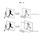
- FIG. 2 is a diagram illustrating an example of the adjustment of depth values of video images and graphic images for natural reproduction of the video images and the graphic images in a case where the video images and the graphic images are reproduced together.
- the graphic images may have a greater depth value than the video images.
- time points to display graphic images are determined in advance.
- a depth value of the graphic images may be adjusted with reference to a depth value of video images, which are to be reproduced together with the graphic images, while an author authors the presentation graphics stream or the text subtitle stream, such that the depth value of the graphic images does not affect the depth value of the video images.
- Interactive graphics streams for displaying menus may be two types of interactive graphics streams.
- One type of the interactive graphics streams is an always-on interactive graphics stream for displaying an always-on menu, which appears and disappears at predetermined time points
- the other type of the interactive graphics streams is a pop-up interactive graphics stream for displaying a pop-up menu, which may appear at predetermined time points and appears and disappears by a command user operation (UOP).
- UOP command user operation
- an author knows a depth value of video images to be displayed together with the menu, and thus, the author may adjust a depth value of graphic images during the authoring stage, so as not to affect the depth impression of the video images.
- the pop-up menu appears and disappears in a screen image based on inputs of a user, and thus, an author may not know depth values of video images that are reproduced together while the pop-up menu is actually displayed. Depth values of graphic images may decrease to be less than depth values of video images.
- the depth impression of video images is adjusted as shown in FIG. 2 to prevent depth values of graphic images from decreasing to be less than depth values of the video images while the video images and the graphic images are reproduced together.
- the upper part of FIG. 2 is a diagram illustrating an example of video images that are 2-dimensionally reproduced in a case where a pop-up menu is reproduced by a UOP while the video images are being 3-dimensionally reproduced.
- the upper left part of FIG. 2 shows that the video images are 3-dimensionally reproduced.
- the depth value of the video images reproduced together with the pop-up menu may be adjusted in the examples, such that the depth value of the video images becomes identical to a depth value of a screen image, that is, a depth value of a screen position.
- a depth value of a pop-up menu may be identical to or greater than a depth value of a screen position.
- the pop-up menu has a depth value larger than that of the video images, and thus, the video images and graphic images are naturally reproduced.
- FIG. 2 shows that, in response to a user requesting a pop-up menu to be displayed while video images are 3-dimensionally reproduced, the video images and the pop-up menu are reproduced together, such that the video images are formed at a greater depth than a screen image.
- a depth value of a pop-up menu may be substantially identical to or greater than a depth value of a screen position.
- the pop-up menu In response to the depth value of video images decreasing to be less than the depth value of a screen position, the pop-up menu has a depth value greater than the depth value of the video images, and thus, the video images and graphic images are naturally reproduced.
- Video image processing apparatuses may be implemented as video image processing apparatuses for processing video images to have the depth impression as illustrated in FIG. 2 in a case where the video images and a pop-up menu are reproduced together.
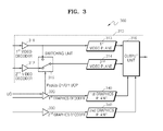
- FIGS. 3 and 4 illustrate examples of video image processing apparatuses 300 and 400 for 2-dimensionally reproducing video images as shown in the upper part of FIG. 2 in a case where the video images and a pop-up menu are reproduced together.
- the example of the video image processing apparatus 300 includes a video processing unit 310, a first graphics decoder 320, a second graphics decoder 330, a first graphics plane 340, and a second graphics plane 350.
- the video processing unit 310 includes a first video decoder 311, a second video decoder 312, a first video plane 313, a second video plane 314, a switching unit 315, and an output unit 316.
- the first video decoder 311 receives one of a left-eye video stream and a right-eye video stream
- the second video decoder 311 receives the other one of the left-eye video stream and the right-eye video stream.
- the left-eye video stream is assumed to be input to the first video decoder 311 and the right-eye video stream is assumed to be input to the second video decoder 312, for convenience and conciseness.
- the first video decoder 311 decodes the left-eye video stream and forms left-eye video images on the first video plane 313 by using the decoded left-eye video stream.
- the second video decoder 312 decodes the right-eye video stream and forms right-eye video images on the second video plane 314 by using the decoded right-eye video stream.
- the first video plane 313 and the second video plane 314 temporarily store the left-eye video image and the right-eye video image formed by the first video decoder 311 and the second video decoder 312, respectively.
- the output unit 316 alternately outputs the video images formed on the first video plane 313 and the second video plane 314.
- the first graphics decoder 320 and the second graphics decoder 330 decode graphics streams.
- an interactive graphics stream is assumed to be a stereoscopic interactive graphics stream including a left-eye interactive graphics stream and a right-eye interactive graphics stream.
- the first graphics decoder 320 decodes the left-eye interactive graphics stream and forms left-eye graphic images on the first graphics plane 340, whereas the second graphics decoder 320 decodes the right-eye interactive graphics stream and forms right-eye graphic images on the second graphics plane 350.
- the first graphics plane 340 and the second graphics plane 350 temporarily store the left-eye graphic image and the right-eye graphic image formed by the first graphics decoder 320 and the second graphics decoder 330, respectively.
- the output unit 316 alternately outputs the graphic images formed on the first graphics plane 340 and the second graphics plane 350.
- an interactive graphics stream is a stereoscopic interactive graphics stream
- a left-eye interactive graphics stream and a right-eye interactive graphics stream may be generated, such that the graphics streams have individual depth values with respect to each of the graphic objects included in graphic images.
- the graphic objects are respectively shifted to the left or to the right according to offset values with respect to the graphic objects in the left-eye graphic image and the right-eye graphic image formed on the first graphics plane 340 and the second graphics plane 350.
- the left-eye graphic image and the right-eye graphic image respectively generated by the first graphics decoder 320 and the second graphics decoder 330 have individual depth values with respect to each of the graphic objects, and thus, 3D graphic images output by the output unit 316 have individual stereoscopic impressions with respect to each of the graphic objects.
- the video image processing apparatus 300 may receive a UOP via a user interface (not shown). While watching 3D video images, a user may issue a command for displaying a pop-up menu and/or a command for terminating the display of a pop-up menu to the video image processing apparatus 300.
- a UOP for displaying a pop-up menu will be referred to as a pop-up interactive graphics stream activating UOP (PopUp On UOP)
- a UOP for terminating display of a pop-up menu will be referred to as a pop-up interactive graphics stream deactivating UOP (PopUp Off UOP).
- the PopUp On/Off UOPs are transmitted to one or more of the first graphics decoder 320 and the second graphics decoder 330 via the user interface.
- the PopUp On/Off UOPs are assumed to be transmitted to the first graphics decoder 320 for convenience and conciseness.
- the first graphics decoder 320 which has received the PopUp On/Off UOPs, transmits the PopUp On/Off UOPs to the second graphics decoder 330. Furthermore, the first graphics decoder 320 transmits the PopUp On/Off UOPs to the switching unit 315. In response to the switching unit 315 receiving the PopUp On/Off UOPs from the first graphics decoder 320, the switching unit 315 controls the video processing unit 310, such that the second video decoder 312 forms right-eye video images on the second video plane 314 or the first video decoder 311 forms left-eye video images on the first video plane 313.
- the first graphics decoder 320 transmits the PopUp On UOP to the second graphics decoder 330.
- the first graphics decoder 320 and the second graphics decoder 330 respectively decode a left-eye interactive graphics stream and a right-eye interactive graphics stream and respectively form left-eye graphic images and right-eye graphic images on the first graphics plane 340 and the second graphics plane 350.
- the output unit 316 reproduces 3D graphic images by alternately outputting the left-eye graphic images and the right-eye graphic images formed on the first graphics plane 340 and the second graphics plane 350.
- the first graphics decoder 320 transmits the PopUp On UOP from the user to the switching unit 315.
- the switching unit 315 controls the video processing unit 310 to reproduce 2D video images by generating either left-eye video images or right-eye video images.
- the switching unit 315 controls the first video decoder 311, not the second video decoder 312, to form left-eye video images on the second video plane 314. Since the first video decoder 311 generates left-eye video images from a left-eye video stream, left-eye video images are formed on the second video plane 314 by the first video decoder 311.
- FIG. 3 shows that the switching unit 315 controls whether the first video decoder 311 forms video images on the second video plane 314 or the second video decoder 312 forms video images on the second video plane 314.
- the switching unit 315 may also control, such that right-eye video images are formed on the second video plane 314 and either the first video decoder 311 forms video images on the first video plane 313 or the second video decoder 312 forms video images on the first video plane 313.
- the output unit 316 alternately outputs video images formed on the first video plane 313 and the second video plane 314. Since the left-eye video images are formed on both of the first video plane 313 and the second video plane 314, the output unit 316 reproduces 2D video images by successively reproducing the left-eye video images twice.
- the output unit 316 overlays 3D graphic images on the 2D video images and reproduces the 3D graphic images and the 2D video images.
- a depth value of a pop-up menu may be equal to or greater than a depth value of a video image, and thus, in a case where video images are 2-dimensionally reproduced, a pop-up menu reproduced as 3D graphic images has a depth value greater than that of the video images, and thus, the video images and the graphic images are naturally reproduced.
- the first graphics decoder 320 and the second graphics decoder 330 finish forming the left-eye graphic images and the right-eye graphic images on the first graphics plane 340 and the second graphics plane 350, respectively, by using the pop-up interactive graphics stream.
- the first graphics decoder 320 also transmits the PopUp Off UOP to the switching unit 315.
- the switching unit 315 receives the PopUp Off UOP from the first graphics decoder 320 and controls the second video decoder 312, not the first video decoder 311, to form video images on the second video plane 314. Under the control of the switching unit 315, the second video decoder 312 forms right-eye video images on the second video plane 314.
- the output unit 316 reproduces 3D video images by alternately outputting the left-eye video images formed on the first video plane 313 and the right-eye video images formed on the second video plane 314.
- the first graphics decoder 320 Prior to transmission of a PopUp On/Off UOP from a user to the switching unit 315, the first graphics decoder 320 determines whether an interactive graphics stream to be processed is a pop-up interactive graphics stream for displaying a pop-up menu and, in response to the interactive graphics stream being a pop-up interactive graphics stream, may transmit the PopUp On/Off UOP from the user to the switching unit 315. To determine whether an interactive graphics stream is a pop-up interactive graphics stream, the first graphics decoder 320 may analyze a User Interface Model field included in an ICS Interactive Composition Segment of an interactive graphics stream and determine whether the interactive graphics stream to be output is a pop-up interactive graphics stream. In response to the interactive graphics stream being a pop-up interactive graphics stream, the first graphics decoder 320 transmits the PopUp On/Off UOP from the user to the switching unit 315.
- the video image processing apparatus may reproduce 2D video images by forming either left-eye video images or right-eye video images on both of a first video plane and a second video plane.
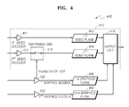
- FIG. 4 is a diagram illustrating another example of the video image processing apparatus 400.
- the video image processing apparatus 400 includes a video processing unit 410, a first graphics decoder 420, a second graphics decoder 430, a first graphics plane 440, and a second graphics plane 450.
- the video processing unit 410 includes a first video decoder 411, a second video decoder 412, a first video plane 413, a second video plane 414, a switching unit 415, and an output unit 416.
- Components of the video image processing apparatus 400 of FIG. 4 are substantially identical to the components of the video image processing apparatus 300 of FIG. 3 except for the switching unit 415, and thus, descriptions thereof are omitted for conciseness.
- the switching unit 314 of the video image processing apparatus 300 of FIG. 3 is different from the switching unit 415 of the video image processing apparatus 400 which controls the second video decoder 412 to form video images on the second video plane 414 or not to form video images on the second video plane 414.
- the video processing unit 410 is reproducing 3D video images by respectively forming left-eye video images and right-eye video images on the first video plane 413 and second video plane 414
- the first graphics decoder 420 transmits the PopUp On UOP to the second graphics decoder 430.
- the first graphics decoder 420 and the second graphics decoder 430 respectively decode a left-eye interactive graphics stream and a right-eye interactive graphics stream and respectively form left-eye graphic images and right-eye graphic images on the first graphics plane 440 and the second graphics plane 450.
- the output unit 416 reproduces 3D graphic images by alternately outputting the left-eye graphic images and the right-eye graphic images respectively formed on the first graphics plane 440 and the second graphics plane 450.
- the first graphics decoder 420 transmits the PopUp On UOP to the switching unit 415.
- the switching unit 415 controls the second video decoder 412 so as to not form video images on the second video plane 414.
- FIG. 4 shows that the switching unit 415 controls the second video decoder 412 to form video images on the second video plane 414 or controls the second video decoder 412 not to form video images on the second video plane 414.
- the switching unit 415 may also control the second video decoder 412, such that right-eye video images are formed on the second video plane 414 and either the first video decoder 411 forms video images on the first video plane 413 or the first video decoder 411 does not form video images on the first video plane 413.
- the output unit 416 alternately outputs video images formed on the first video plane 413 and the second video plane 414. Under the control of the switching unit 415, video images are not formed on the second video plane 414, and thus, the output unit 416 reproduces the left-eye video images formed on the first video plane 413 and reproduces blank video images on the second video plane 414.
- the blank video images are entirely black or entirely white video images.
- video images reproduced by the output unit 416 are 2D video images.
- the first graphics decoder 420 and the second graphics decoder 430 finish forming the left-eye graphic images and the right-eye graphic images on the first graphics plane 440 and the second graphics plane 450, respectively, by using the pop-up interactive graphics stream.
- the first graphics decoder 420 also transmits the PopUp Off UOP to the switching unit 415.
- the switching unit 415 receives the PopUp Off UOP from the first graphics decoder 420 and controls the second video decoder 412 to form video images on the second video plane 414.
- the second video decoder 412 decodes a right-eye video stream and forms right-eye video images on the second video plane 414 under the control of the switching unit 415.
- the output unit 416 reproduces 3D video images by alternately outputting the left-eye video images formed on the first video plane 413 and the right-eye video images formed on the second video plane 414.
- the video image processing apparatus may reproduce 2D video images by controlling the video processing unit 410 to form or not to form either left-eye video images or right-eye video images on one of the first video plane and second video plane.
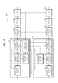
- FIG. 5 is a diagram illustrating another example of a video image processing apparatus 500.
- FIG. 5 shows a video image processing apparatus for reproducing a pop-up menu and video images together with a stereoscopic impression that, as shown in the lower part of FIG. 2 , the video images are located deeper than the pop-up menu.
- the video image processing apparatus 500 includes a video processing unit 510, a graphics decoder 520, a first graphics plane 530, and a second graphics plane 540.
- the video processing unit 510 includes a first video decoder 511, a second video decoder 512, a first video plane 513, a second video plane 514, a switching unit 515, a shifter 516, and an output unit 517.
- particular depth values of a video plane in response to a pop-up menu being displayed may be defined.
- Information for a video plane to have particular depth values may be included in a memory (not shown) within the video image processing apparatus 500, in a video stream, in a graphics stream, or in metadata with respect to a video stream.
- information for a video plane to have particular depth values will be referred to as a video plane offset value, which is information indicating a distance by which left-eye video images or right-eye video images are shifted to the left or to the right.
- the graphics decoder 520 determines whether an interactive graphics stream to be processed is a pop-up interactive graphics stream for displaying a pop-up menu and, in response to the interactive graphics stream being a pop-up interactive graphics stream, transmits the PopUp On UOP from the user to the switching unit 515.
- the switching unit 515 controls the first video decoder 511, not the second video decoder 512, to form video images on the second video plane 514.
- the switching unit 515 controls the first video decoder 511, not the second video decoder 512, to form video images on the second video plane 514.
- left-eye video images are formed on both the first video plane 513 and the second video plane 514.
- the graphics decoder 520 extracts video plane offset values from a memory (not shown) in the video image processing apparatus 500, a video stream, a graphics stream, or metadata with respect to a video stream.
- the graphics decoder 520 transmits an extracted video plane offset value to the shifter 516.
- the shifter 516 shifts video images formed on the first video plane 513 and the second video plane 514 to the left and to the right based on the video plane offset values, respectively.
- the shifter 516 In response to a video plane offset value being a positive value, the shifter 516 generates two new video images by shifting left-eye video images formed on the first video plane 513 to the left by the video plane offset value and shifting right-eye video images formed on the second video plane 514 to the right by the video plane offset value.
- the output unit 517 alternately outputs the two video images generated by the shifter 516.
- video images reproduced by the output unit 517 are 3D video images having the same depth value.
- depth values of 3D video images formed by two video images generated by the shifter 516 decrease, thus giving a stereoscopic impression that the 3D video images are located deeper.
- the graphics decoder 520 In response to the graphics decoder 520 receiving a PopUp On UOP from a user, the graphics decoder 520 decodes an interactive graphics stream and generates graphic images. In FIG. 5 , a graphics stream is assumed to be not a stereoscopic graphics stream.
- Information for 3-dimensionally reproducing a graphics stream may be included in the memory in the video image processing apparatus 500, in a graphics stream, or in metadata with respect to a graphics stream.
- the video image processing apparatus 500 may extract information for 3-dimensionally reproducing a graphics stream from the memory, the graphics stream, or the metadata with respect to the graphics stream and may reproduce 3D graphic images from a graphics stream by using the information for 3-dimensionally reproducing a graphics stream.
- the information for 3-dimensionally reproducing a graphics stream may include graphic object offset information, graphic plane offset information, or any combination thereof.
- the graphic plane offset information is information for giving the same depth value to a graphic image including a plurality of graphic objects, whereas the graphic object offset information is information for giving an individual depth value to each of a plurality of graphic objects included in a graphic image.
- the graphic plane offset information includes offset values with respect to a graphic plane.
- the offset values with respect to a graphic plane are values indicating distances by which a single graphic image generated by decoding a single graphics stream is shifted to the left and to the right for generating a 3D graphic image having the same depth value overall.
- the graphic object offset information includes object identifiers for identifying each of a plurality of graphic objects included in a graphic image and offset values with respect to graphic objects that are to be applied to identified objects.
- the offset values with respect to the graphic objects are values indicating that the corresponding graphic objects are to be shifted to the left and to the right, such that each of the graphic objects has an individual depth value.
- the graphics decoder 520 extracts information for 3-dimensionally reproducing a graphics stream from the memory in the video image processing apparatus 500, the graphics stream, or metadata with respect to the graphics stream and may 3-dimensionally reproduce a graphic image by giving the same depth value to an entire graphic image or giving an individual depth value to each of the graphic objects included in the graphic image, that is, each of the menus or buttons, by extracting graphic object offset information or graphic plane offset information from the information for 3-dimensionally reproducing a graphics stream.
- the graphics decoder 520 In a case where the graphics decoder 520 extracts the graphic plane offset information from the information for 3-dimensionally reproducing a graphics stream, the graphics decoder 520 shifts the entire graphic image by offset values with respect to a graphic plane included in the graphic plane offset information and forms a left-eye graphic image and a right-eye graphic image on the first graphics plane 530 and the second graphics plane 540, respectively.
- the output unit 517 may reproduce 3D graphic images by alternately outputting the left-eye graphic images and the right-eye graphic images respectively formed on the first graphics plane 530 and the second graphics plane 540. In this case, an entire 3D graphic image has the same depth value.
- the graphics decoder 520 extracts graphic object identifiers from the graphic object offset information and gives an individual depth value to each of the identified graphic objects.
- the graphics decoder 520 respectively forms left-eye graphic images and right-eye graphic images on the first graphics plane 340 and the second graphics plane 350, respectively, by using offset values with respect to the graphic objects which indicate distances by which the corresponding graphic objects are shifted to the left and the other corresponding graphic objects are shifted to the right, such that each of the graphic objects is shifted to the left or to the right by the corresponding offset value.
- each of the graphic objects in a 3D graphic image output by the output unit 517 has a separate stereoscopic impression.
- the graphics decoder 520 finishes forming graphic images by using a pop-up interactive graphics stream.
- the graphics decoder 520 also transmits the PopUp Off UOP to the switching unit 515.
- the switching unit 515 receives the PopUp Off UOP from the graphics decoder 520 and controls the second video decoder 512 to form video images on the second video plane 514.
- the graphics decoder 520 in response to the graphics decoder 520 receiving the PopUp Off UOP, notifies reception of the PopUp Off UOP to the shifter 516, so that the shifter 516 does not generate a new graphic image by shifting video images formed on the first video plane 513 and the second video plane 514 to the left or to the right.
- the output unit 517 reproduces 3D video images by alternately outputting left-eye video images formed on the first video plane 513 and right-eye video images formed on the second video plane 514.
- FIG. 6 is a diagram illustrating an example of a graphics decoding apparatus 600.
- the graphics decoding apparatus 600 includes a left-eye graphics decoder 610, a right-eye graphics decoder 620, a left-eye graphics plane 630, a right-eye graphics plane 640, offset value applying units (referred to hereinafter as an 'offset') 650 and 660, and a color look-up tables (CLUTs) 670 and 680.
- a left-eye graphics decoder 610 includes a left-eye graphics decoder 610, a right-eye graphics decoder 620, a left-eye graphics plane 630, a right-eye graphics plane 640, offset value applying units (referred to hereinafter as an 'offset') 650 and 660, and a color look-up tables (CLUTs) 670 and 680.
- CLUTs color look-up tables
- the left-eye graphics decoder 610 includes a coded data buffer 611, a stream graphics processor 613, a composition buffer 615, a decoded object buffer 617, and a graphics controller 619.
- the right-eye graphics decoder 620 includes a coded data buffer 621, a stream graphic processor 623, a composition buffer 625, and a decoded object buffer 627.
- the left-eye graphics decoder 610 decodes a left-eye graphics stream
- the right-eye graphics decoder 620 decodes a right-eye graphics stream.
- the coded data buffers 611 and 621 temporarily store the left-eye interactive graphics stream and the right-eye interactive graphics stream, respectively, and transmit the left-eye interactive graphics stream and the right-eye interactive graphics stream to the stream graphic processor 613 and 623, respectively.
- the stream graphic processor 613 and 623 respectively decode the left-eye interactive graphics stream and the right-eye interactive graphics stream, transmit button image object data to the decoded object buffers 617 and 627, and transmit button configuration information to the composition buffers 615 and 625.
- the graphics controller 619 forms images to be output with respect to each object data transmitted to the decoded object buffers 617 and 627 by referring to the corresponding configuration information and transmits the formed images respectively to the left-eye graphics plane 630 and the right-eye graphics plane 640.
- the graphics controller 619 fills colors of the images transmitted to the left-eye graphics plane 630 and right-eye graphics plane 640 by referring to the CLUTs 670 and 680, according to color information included in the corresponding configuration information.
- An output unit (not shown) displays 3D graphic images by alternately outputting images formed on the left-eye graphics plane 630 and the right-eye graphics plane 640.
- each of the graphic objects in a 3D graphic image may have an individual depth value.
- the offset value applying units 650 and 660 perform no functions.
- the graphics decoding apparatus 600 may not use both the left-eye graphics decoder 610 and the right-eye graphics decoder 620, and thus, the graphics decoding apparatus 600 decodes a graphics stream by using a single graphics decoder, for example, the left-eye graphics decoder 610.
- the left-eye graphics decoder 610 forms images to be output by decoding the graphics stream, finds the formed images from the decoded object buffer 617, and transmits the images to the left-eye graphics plane 630 and the right-eye graphics plane 640.
- the graphics controller 619 extracts information for 3-dimensionally reproducing a graphics stream from a memory (not shown) in a video image processing apparatus, the graphics stream, or metadata with respect to the graphics stream.
- the information for 3-dimensionally reproducing a graphics stream may include graphic object offset information, graphic plane offset information, or any combination thereof.
- the graphics controller 619 may extract graphic plane offset information, extract offset values with respect to a graphic plane, and transmit the offset values to the offset value applying units 650 and 660.
- the offset value applying units 650 and 660 receive offset values with respect to a graphic plane from the graphics controller 619 and shift images transmitted to the left-eye graphics plane 630 and the right-eye graphics plane 640 to the left and to the right, or to the right and to the left by the offset values with respect to the graphic plane.
- the graphics controller 619 refers to the CLUTs 670 and 680 and fills colors of the images transmitted to the left-eye graphics plane 630 and the right-eye graphics plane 640.
- An output unit reproduces 3D graphic images by alternately outputting the images formed in the left-eye graphics plane 630 and the right-eye graphics plane 640.
- graphic images reproduced by the output unit 517 are 3D graphic images having the same depth value.
- the graphics controller 619 For the graphics controller 619 to give an individual depth value to each of the graphic objects included in a graphic image, the graphics controller 619 extracts graphic object offset information from the information for 3-dimensionally reproducing a graphics stream, extracts object identifiers and offset values with respect to graphic objects from the graphic object offset information, and transmits the object identifiers and the offset values to the offset value applying units 650 and 660.
- the offset value applying units 650 and 660 receive the object identifiers and the offset values with respect to graphic objects from the graphics controller 619 and shift each of the graphic objects included in images transmitted to the left-eye graphics plane 630 and the right-eye graphics plane 640 to the left and to the right or to the right and to the left by the offset values with respect to the graphic plane.
- the graphics controller 619 refers to the CLUTs 670 and 680 and fills colors of the images transmitted to the left-eye graphics plane 630 and the right-eye graphics plane 640.
- the output unit 517 reproduces 3D graphic images by alternately outputting the images formed in the left-eye graphics plane 630 and the right-eye graphics plane 640.
- graphic images reproduced by the output unit 517 are 3D graphic images having the same depth value.
- An output unit reproduces 3D graphic images by alternately outputting the images formed in the left-eye graphics plane 630 and the right-eye graphics plane 640.
- a graphic image reproduced by the output unit is a 3D graphic image in which an individual depth value is given to each of the graphic objects included in the graphic image.
- the graphics controller 619 receives a UOP from a user via a user interface.
- the graphics controller 619 controls the graphics decoding apparatus 600 according to the UOP from the user.
- the graphics controller 619 analyzes a User Interface Model field included in an ICS Interactive Composition Segment of an interactive graphics stream and determines whether a decoded interactive graphics stream is a pop-up interactive graphics stream.
- the graphics controller 619 transmits the PopUp On/Off UOP to a video processing unit (not shown).
- the video processing unit may reproduce 2D video images by forming either left-eye video images or right-eye video images or may reproduce 3D video images having a depth value smaller than that of a pop-up menu by generating two new video images by shifting one of left-eye video images and right-eye video images to the left and to the right by video plane offset values.
- the video processing unit may generate both left-eye video images and right-eye video images, so that 3D video images may be reproduced.
- the video plane offset values may be included in a memory (not shown) in a video image processing apparatus, in a video stream, in a graphics stream, or in metadata with respect to a video stream.
- an example of a graphics decoding apparatus may generate a 3D graphic image having the same depth value overall or a 3D graphic image in which an individual depth value is given to each graphic object included in the 3D graphic image by using a graphics stream.
- FIG. 7 is a diagram illustrating an example of metadata with respect to a graphics stream.
- the metadata includes information for 3-dimensionally reproducing a graphics stream.
- the information for 3-dimensionally reproducing a graphics stream may also be included in a memory, in a video image processing apparatus, or in a graphics stream.
- the metadata with respect to a graphics stream may include graphic object output time information indicating time points for outputting graphic objects included in the graphics stream and the graphic object offset information.
- a graphic object may correspond to a button or a subtitle included in a graphic image displayed by the graphics stream.
- the graphic object output time information indicates time points for outputting a menu or a subtitle, that is, a graphic object, and may be indicated as a presentation time stamp (PTS) value, such as lCS, PCS, and DPS.
- PTS presentation time stamp
- a graphic image displayed by a graphics stream includes one or more graphic objects for displaying a menu, a button, a subtitle, etc.
- the metadata with respect to a graphics stream may include graphic object offset information for giving an individual depth value to each graphic object included in a graphic image, a graphic plane offset information, or any combination thereof for giving the same depth value to an entire graphic image.
- the graphic object offset information may include object identifiers for identifying graphic objects, offset values with respect to the graphic objects, and hole compensation information.
- the object identifiers are information for identifying particular graphic objects from among graphic objects generated by decoding a graphics stream.
- the offset values with respect to graphic objects may indicate distances by which objects identified by the object identifiers are shifted to the left or to the right.
- the hole compensation information is information for compensating for a hole formed at an original location of a graphic object in response to the graphic object being shifted by an offset value with respect to the graphic object and may include hole region identification information for identifying a hole region and color reference information indicating a color for filling the identified region.
- the hole compensation information may include information regarding a picture to be inserted to a hole region, instead of color reference information.
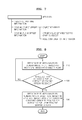
- FIG. 8 is a flowchart illustrating an example of a method of processing video images.
- a video image processing apparatus reproduces 3D video images by generating left-eye video images and right-eye video images from a video stream (operation 810).
- the video image processing apparatus determines whether a decoded interactive graphics stream is pop-up interactive graphics stream to be activated according to the request.
- the request or command may correspond to UOIP from the user.
- the video image processing apparatus If the decoded interactive graphics stream is a pop-up interactive graphics stream to be activated according to the UOP from the user, the video image processing apparatus generates either left-eye video images or right-eye video images from the video stream and reproduces 2D video images (operation 830).
Landscapes
- Engineering & Computer Science (AREA)
- Multimedia (AREA)
- Signal Processing (AREA)
- Computer Graphics (AREA)
- Human Computer Interaction (AREA)
- Testing, Inspecting, Measuring Of Stereoscopic Televisions And Televisions (AREA)
- Processing Or Creating Images (AREA)
Priority Applications (1)
| Application Number | Priority Date | Filing Date | Title |
|---|---|---|---|
| EP13161004.0A EP2615835A3 (de) | 2009-02-17 | 2010-02-16 | Verfahren und Vorrichtung zur Verarbeitung eines Videobilds |
Applications Claiming Priority (4)
| Application Number | Priority Date | Filing Date | Title |
|---|---|---|---|
| KR20090013152 | 2009-02-17 | ||
| US16038209P | 2009-03-16 | 2009-03-16 | |
| KR1020100013514A KR101659576B1 (ko) | 2009-02-17 | 2010-02-12 | 영상 처리 방법 및 장치 |
| PCT/KR2010/000905 WO2010095835A2 (ko) | 2009-02-17 | 2010-02-16 | 영상 처리 방법 및 장치 |
Publications (2)
| Publication Number | Publication Date |
|---|---|
| EP2400766A2 true EP2400766A2 (de) | 2011-12-28 |
| EP2400766A4 EP2400766A4 (de) | 2012-09-05 |
Family
ID=42758511
Family Applications (2)
| Application Number | Title | Priority Date | Filing Date |
|---|---|---|---|
| EP10743910A Ceased EP2400766A4 (de) | 2009-02-17 | 2010-02-16 | Verfahren und vorrichtung zur verarbeitung von videobildern |
| EP13161004.0A Withdrawn EP2615835A3 (de) | 2009-02-17 | 2010-02-16 | Verfahren und Vorrichtung zur Verarbeitung eines Videobilds |
Family Applications After (1)
| Application Number | Title | Priority Date | Filing Date |
|---|---|---|---|
| EP13161004.0A Withdrawn EP2615835A3 (de) | 2009-02-17 | 2010-02-16 | Verfahren und Vorrichtung zur Verarbeitung eines Videobilds |
Country Status (8)
| Country | Link |
|---|---|
| US (1) | US9445034B2 (de) |
| EP (2) | EP2400766A4 (de) |
| JP (1) | JP5593333B2 (de) |
| KR (1) | KR101659576B1 (de) |
| CN (1) | CN102318353B (de) |
| BR (1) | BRPI1008574A2 (de) |
| MY (1) | MY157101A (de) |
| WO (1) | WO2010095835A2 (de) |
Families Citing this family (12)
| Publication number | Priority date | Publication date | Assignee | Title |
|---|---|---|---|---|
| US20110255003A1 (en) * | 2010-04-16 | 2011-10-20 | The Directv Group, Inc. | Method and apparatus for presenting on-screen graphics in a frame-compatible 3d format |
| JP5668385B2 (ja) * | 2010-09-17 | 2015-02-12 | ソニー株式会社 | 情報処理装置、プログラムおよび情報処理方法 |
| KR20120037858A (ko) * | 2010-10-12 | 2012-04-20 | 삼성전자주식회사 | 입체영상표시장치 및 그 ui 제공 방법 |
| JP2012100102A (ja) * | 2010-11-02 | 2012-05-24 | Sony Corp | 立体画像データ送信装置、立体画像データ送信方法、立体画像データ受信装置および立体画像データ受信方法 |
| JP5789960B2 (ja) * | 2010-11-18 | 2015-10-07 | セイコーエプソン株式会社 | 表示装置、表示装置の制御方法、及び、プログラム |
| EP2506263A1 (de) * | 2011-03-31 | 2012-10-03 | Thomson Licensing | Stereoskopischer Szenengraph zur Definition von 3D- und 2D-kompatiblen graphischen Objekten |
| JP5815326B2 (ja) * | 2011-08-12 | 2015-11-17 | ルネサスエレクトロニクス株式会社 | 動画像復号装置及び画像表示装置 |
| KR20140107107A (ko) * | 2011-12-28 | 2014-09-04 | 파나소닉 주식회사 | 영상재생장치, 영상재생방법, 영상재생 프로그램, 영상송신장치, 영상송신방법 및 영상송신 프로그램 |
| EP2627093A3 (de) * | 2012-02-13 | 2013-10-02 | Thomson Licensing | Verfahren und Vorrichtung zum Einfügen einer 3D-Grafikanimation in einen 3D-Stereoinhalt |
| CN103517051B (zh) * | 2012-06-28 | 2016-07-06 | 联想(北京)有限公司 | 控制方法和电子设备 |
| US11237695B2 (en) * | 2012-10-12 | 2022-02-01 | Sling Media L.L.C. | EPG menu with a projected 3D image |
| US9948913B2 (en) | 2014-12-24 | 2018-04-17 | Samsung Electronics Co., Ltd. | Image processing method and apparatus for processing an image pair |
Citations (3)
| Publication number | Priority date | Publication date | Assignee | Title |
|---|---|---|---|---|
| WO2008038205A2 (en) * | 2006-09-28 | 2008-04-03 | Koninklijke Philips Electronics N.V. | 3 menu display |
| EP1909510A1 (de) * | 2005-07-19 | 2008-04-09 | Olympus Imaging Corporation | Einrichtung und programm zur bildausgabe |
| WO2008115222A1 (en) * | 2007-03-16 | 2008-09-25 | Thomson Licensing | System and method for combining text with three-dimensional content |
Family Cites Families (23)
| Publication number | Priority date | Publication date | Assignee | Title |
|---|---|---|---|---|
| JPH07325934A (ja) * | 1992-07-10 | 1995-12-12 | Walt Disney Co:The | 仮想世界に向上したグラフィックスを提供する方法および装置 |
| JPH09139957A (ja) * | 1995-11-14 | 1997-05-27 | Mitsubishi Electric Corp | グラフィック表示装置 |
| JP3709000B2 (ja) | 1995-12-12 | 2005-10-19 | ペンタックス株式会社 | 超広角ズームレンズカメラ |
| US5971589A (en) * | 1996-05-06 | 1999-10-26 | Amadasoft America, Inc. | Apparatus and method for managing and distributing design and manufacturing information throughout a sheet metal production facility |
| JPH11113028A (ja) * | 1997-09-30 | 1999-04-23 | Toshiba Corp | 3次元映像表示装置 |
| WO1999030280A1 (en) | 1997-12-05 | 1999-06-17 | Dynamic Digital Depth Research Pty. Ltd. | Improved image conversion and encoding techniques |
| US6717578B1 (en) | 1998-02-17 | 2004-04-06 | Sun Microsystems, Inc. | Graphics system with a variable-resolution sample buffer |
| JP4610799B2 (ja) | 2001-06-25 | 2011-01-12 | オリンパス株式会社 | 立体観察システム、及び内視鏡装置 |
| WO2004021285A1 (ja) | 2002-08-27 | 2004-03-11 | Sharp Kabushiki Kaisha | 最適な再生モードでコンテンツを再生できるコンテンツ再生装置 |
| JP4072674B2 (ja) | 2002-09-06 | 2008-04-09 | ソニー株式会社 | 画像処理装置および方法、記録媒体、並びにプログラム |
| KR100436904B1 (ko) | 2002-09-06 | 2004-06-23 | 강호석 | 2차원이미지에 대한 입체영상생성방법 |
| EP1437898A1 (de) | 2002-12-30 | 2004-07-14 | Koninklijke Philips Electronics N.V. | Videofilterung für Stereobilder |
| JP2005229384A (ja) | 2004-02-13 | 2005-08-25 | Nippon Hoso Kyokai <Nhk> | マルチメディア情報配受信システム、マルチメディア情報配信装置およびマルチメディア情報受信装置 |
| US7697750B2 (en) | 2004-12-06 | 2010-04-13 | John Castle Simmons | Specially coherent optics |
| JP2006191357A (ja) | 2005-01-06 | 2006-07-20 | Victor Co Of Japan Ltd | 再生装置および再生プログラム |
| DE102006030990A1 (de) * | 2005-11-14 | 2007-05-16 | Univ Muenster Wilhelms | Verfahren und Anordnung zum monoskopischen Darstellen wenigstens eines Bereiches eines Bildes auf einer autostereoskopischen Anzeigevorrichtung |
| US20070247477A1 (en) * | 2006-04-21 | 2007-10-25 | Lowry Gregory N | Method and apparatus for processing, displaying and viewing stereoscopic 3D images |
| EP2105032A2 (de) * | 2006-10-11 | 2009-09-30 | Koninklijke Philips Electronics N.V. | Erzeugung dreidimensionaler grafikdaten |
| US8594180B2 (en) * | 2007-02-21 | 2013-11-26 | Qualcomm Incorporated | 3D video encoding |
| JP4382837B2 (ja) | 2007-06-07 | 2009-12-16 | シャープ株式会社 | 表示システムおよび画像処理装置 |
| EP2235957A1 (de) * | 2007-12-20 | 2010-10-06 | Koninklijke Philips Electronics N.V. | Bildkodierungsverfahren zur stereoskopischen darstellung |
| US8335425B2 (en) * | 2008-11-18 | 2012-12-18 | Panasonic Corporation | Playback apparatus, playback method, and program for performing stereoscopic playback |
| EP2400767A4 (de) | 2009-02-17 | 2012-09-05 | Samsung Electronics Co Ltd | Verfahren und vorrichtung zur verarbeitung grafischer bilder |
-
2010
- 2010-02-12 KR KR1020100013514A patent/KR101659576B1/ko active IP Right Grant
- 2010-02-16 EP EP10743910A patent/EP2400766A4/de not_active Ceased
- 2010-02-16 WO PCT/KR2010/000905 patent/WO2010095835A2/ko active Application Filing
- 2010-02-16 JP JP2011550058A patent/JP5593333B2/ja not_active Expired - Fee Related
- 2010-02-16 EP EP13161004.0A patent/EP2615835A3/de not_active Withdrawn
- 2010-02-16 CN CN201080008651.5A patent/CN102318353B/zh active Active
- 2010-02-16 MY MYPI2011003816A patent/MY157101A/en unknown
- 2010-02-16 BR BRPI1008574A patent/BRPI1008574A2/pt not_active IP Right Cessation
-
2011
- 2011-08-05 US US13/204,362 patent/US9445034B2/en active Active
Patent Citations (3)
| Publication number | Priority date | Publication date | Assignee | Title |
|---|---|---|---|---|
| EP1909510A1 (de) * | 2005-07-19 | 2008-04-09 | Olympus Imaging Corporation | Einrichtung und programm zur bildausgabe |
| WO2008038205A2 (en) * | 2006-09-28 | 2008-04-03 | Koninklijke Philips Electronics N.V. | 3 menu display |
| WO2008115222A1 (en) * | 2007-03-16 | 2008-09-25 | Thomson Licensing | System and method for combining text with three-dimensional content |
Non-Patent Citations (1)
| Title |
|---|
| See also references of WO2010095835A2 * |
Also Published As
| Publication number | Publication date |
|---|---|
| US9445034B2 (en) | 2016-09-13 |
| EP2615835A2 (de) | 2013-07-17 |
| EP2400766A4 (de) | 2012-09-05 |
| KR20100094375A (ko) | 2010-08-26 |
| WO2010095835A3 (ko) | 2010-11-18 |
| EP2615835A3 (de) | 2013-12-25 |
| MY157101A (en) | 2016-04-29 |
| JP2012518322A (ja) | 2012-08-09 |
| BRPI1008574A2 (pt) | 2016-03-08 |
| CN102318353B (zh) | 2014-07-09 |
| JP5593333B2 (ja) | 2014-09-24 |
| WO2010095835A2 (ko) | 2010-08-26 |
| KR101659576B1 (ko) | 2016-09-30 |
| US20110292176A1 (en) | 2011-12-01 |
| CN102318353A (zh) | 2012-01-11 |
Similar Documents
| Publication | Publication Date | Title |
|---|---|---|
| EP2400766A2 (de) | Verfahren und vorrichtung zur verarbeitung von videobildern | |
| US10158841B2 (en) | Method and device for overlaying 3D graphics over 3D video | |
| US9438879B2 (en) | Combining 3D image and graphical data | |
| KR101634569B1 (ko) | 3d 이미지 데이터의 전송 | |
| JP5809064B2 (ja) | 3d画像データの転送 | |
| US20110018976A1 (en) | Image display apparatus and method for operating the same | |
| US20110293240A1 (en) | Method and system for transmitting over a video interface and for compositing 3d video and 3d overlays | |
| JP5789518B2 (ja) | グラフィック画面処理方法及び装置 | |
| KR20110129903A (ko) | 3d 시청자 메타데이터의 전송 | |
| KR20100046584A (ko) | 영상 디코딩 방법, 영상 출력 방법, 영상 처리 방법 및 그 장치 | |
| KR20110114583A (ko) | 디스플레이 파라미터 설정들의 제어 | |
| US20130266287A1 (en) | Reproduction device and reproduction method | |
| KR20130079044A (ko) | 디스플레이 장치 및 그 제어 방법 |
Legal Events
| Date | Code | Title | Description |
|---|---|---|---|
| PUAI | Public reference made under article 153(3) epc to a published international application that has entered the european phase |
Free format text: ORIGINAL CODE: 0009012 |
|
| 17P | Request for examination filed |
Effective date: 20110816 |
|
| AK | Designated contracting states |
Kind code of ref document: A2 Designated state(s): AT BE BG CH CY CZ DE DK EE ES FI FR GB GR HR HU IE IS IT LI LT LU LV MC MK MT NL NO PL PT RO SE SI SK SM TR |
|
| DAX | Request for extension of the european patent (deleted) | ||
| A4 | Supplementary search report drawn up and despatched |
Effective date: 20120802 |
|
| RIC1 | Information provided on ipc code assigned before grant |
Ipc: H04N 13/00 20060101AFI20120727BHEP Ipc: H04N 13/02 20060101ALI20120727BHEP Ipc: H04N 5/445 20110101ALI20120727BHEP Ipc: H04N 13/04 20060101ALI20120727BHEP Ipc: G06T 7/00 20060101ALI20120727BHEP |
|
| RAP1 | Party data changed (applicant data changed or rights of an application transferred) |
Owner name: SAMSUNG ELECTRONICS CO., LTD. |
|
| 17Q | First examination report despatched |
Effective date: 20130430 |
|
| REG | Reference to a national code |
Ref country code: DE Ref legal event code: R003 |
|
| STAA | Information on the status of an ep patent application or granted ep patent |
Free format text: STATUS: THE APPLICATION HAS BEEN REFUSED |
|
| 18R | Application refused |
Effective date: 20140605 |