EP2400657A1 - Inverter control device and electric compressor for ac motor - Google Patents
Inverter control device and electric compressor for ac motor Download PDFInfo
- Publication number
- EP2400657A1 EP2400657A1 EP10743574A EP10743574A EP2400657A1 EP 2400657 A1 EP2400657 A1 EP 2400657A1 EP 10743574 A EP10743574 A EP 10743574A EP 10743574 A EP10743574 A EP 10743574A EP 2400657 A1 EP2400657 A1 EP 2400657A1
- Authority
- EP
- European Patent Office
- Prior art keywords
- phase
- motor
- cry
- carrier waves
- voltage command
- Prior art date
- Legal status (The legal status is an assumption and is not a legal conclusion. Google has not performed a legal analysis and makes no representation as to the accuracy of the status listed.)
- Granted
Links
Images







Classifications
-
- H—ELECTRICITY
- H02—GENERATION; CONVERSION OR DISTRIBUTION OF ELECTRIC POWER
- H02M—APPARATUS FOR CONVERSION BETWEEN AC AND AC, BETWEEN AC AND DC, OR BETWEEN DC AND DC, AND FOR USE WITH MAINS OR SIMILAR POWER SUPPLY SYSTEMS; CONVERSION OF DC OR AC INPUT POWER INTO SURGE OUTPUT POWER; CONTROL OR REGULATION THEREOF
- H02M7/00—Conversion of AC power input into DC power output; Conversion of DC power input into AC power output
- H02M7/42—Conversion of DC power input into AC power output without possibility of reversal
- H02M7/44—Conversion of DC power input into AC power output without possibility of reversal by static converters
- H02M7/48—Conversion of DC power input into AC power output without possibility of reversal by static converters using discharge tubes with control electrode or semiconductor devices with control electrode
- H02M7/53—Conversion of DC power input into AC power output without possibility of reversal by static converters using discharge tubes with control electrode or semiconductor devices with control electrode using devices of a triode or transistor type requiring continuous application of a control signal
- H02M7/537—Conversion of DC power input into AC power output without possibility of reversal by static converters using discharge tubes with control electrode or semiconductor devices with control electrode using devices of a triode or transistor type requiring continuous application of a control signal using semiconductor devices only, e.g. single switched pulse inverters
- H02M7/5387—Conversion of DC power input into AC power output without possibility of reversal by static converters using discharge tubes with control electrode or semiconductor devices with control electrode using devices of a triode or transistor type requiring continuous application of a control signal using semiconductor devices only, e.g. single switched pulse inverters in a bridge configuration
- H02M7/53871—Conversion of DC power input into AC power output without possibility of reversal by static converters using discharge tubes with control electrode or semiconductor devices with control electrode using devices of a triode or transistor type requiring continuous application of a control signal using semiconductor devices only, e.g. single switched pulse inverters in a bridge configuration with automatic control of output voltage or current
- H02M7/53875—Conversion of DC power input into AC power output without possibility of reversal by static converters using discharge tubes with control electrode or semiconductor devices with control electrode using devices of a triode or transistor type requiring continuous application of a control signal using semiconductor devices only, e.g. single switched pulse inverters in a bridge configuration with automatic control of output voltage or current with analogue control of three-phase output
-
- H—ELECTRICITY
- H02—GENERATION; CONVERSION OR DISTRIBUTION OF ELECTRIC POWER
- H02P—CONTROL OR REGULATION OF ELECTRIC MOTORS, ELECTRIC GENERATORS OR DYNAMO-ELECTRIC CONVERTERS; CONTROLLING TRANSFORMERS, REACTORS OR CHOKE COILS
- H02P27/00—Arrangements or methods for the control of AC motors characterised by the kind of supply voltage
- H02P27/04—Arrangements or methods for the control of AC motors characterised by the kind of supply voltage using variable-frequency supply voltage, e.g. inverter or converter supply voltage
- H02P27/06—Arrangements or methods for the control of AC motors characterised by the kind of supply voltage using variable-frequency supply voltage, e.g. inverter or converter supply voltage using DC to AC converters or inverters
- H02P27/08—Arrangements or methods for the control of AC motors characterised by the kind of supply voltage using variable-frequency supply voltage, e.g. inverter or converter supply voltage using DC to AC converters or inverters with pulse width modulation
-
- H—ELECTRICITY
- H02—GENERATION; CONVERSION OR DISTRIBUTION OF ELECTRIC POWER
- H02M—APPARATUS FOR CONVERSION BETWEEN AC AND AC, BETWEEN AC AND DC, OR BETWEEN DC AND DC, AND FOR USE WITH MAINS OR SIMILAR POWER SUPPLY SYSTEMS; CONVERSION OF DC OR AC INPUT POWER INTO SURGE OUTPUT POWER; CONTROL OR REGULATION THEREOF
- H02M1/00—Details of apparatus for conversion
- H02M1/0003—Details of control, feedback or regulation circuits
- H02M1/0009—Devices or circuits for detecting current in a converter
-
- H—ELECTRICITY
- H02—GENERATION; CONVERSION OR DISTRIBUTION OF ELECTRIC POWER
- H02M—APPARATUS FOR CONVERSION BETWEEN AC AND AC, BETWEEN AC AND DC, OR BETWEEN DC AND DC, AND FOR USE WITH MAINS OR SIMILAR POWER SUPPLY SYSTEMS; CONVERSION OF DC OR AC INPUT POWER INTO SURGE OUTPUT POWER; CONTROL OR REGULATION THEREOF
- H02M7/00—Conversion of AC power input into DC power output; Conversion of DC power input into AC power output
- H02M7/42—Conversion of DC power input into AC power output without possibility of reversal
- H02M7/44—Conversion of DC power input into AC power output without possibility of reversal by static converters
- H02M7/48—Conversion of DC power input into AC power output without possibility of reversal by static converters using discharge tubes with control electrode or semiconductor devices with control electrode
- H02M7/53—Conversion of DC power input into AC power output without possibility of reversal by static converters using discharge tubes with control electrode or semiconductor devices with control electrode using devices of a triode or transistor type requiring continuous application of a control signal
- H02M7/537—Conversion of DC power input into AC power output without possibility of reversal by static converters using discharge tubes with control electrode or semiconductor devices with control electrode using devices of a triode or transistor type requiring continuous application of a control signal using semiconductor devices only, e.g. single switched pulse inverters
- H02M7/539—Conversion of DC power input into AC power output without possibility of reversal by static converters using discharge tubes with control electrode or semiconductor devices with control electrode using devices of a triode or transistor type requiring continuous application of a control signal using semiconductor devices only, e.g. single switched pulse inverters with automatic control of output wave form or frequency
- H02M7/5395—Conversion of DC power input into AC power output without possibility of reversal by static converters using discharge tubes with control electrode or semiconductor devices with control electrode using devices of a triode or transistor type requiring continuous application of a control signal using semiconductor devices only, e.g. single switched pulse inverters with automatic control of output wave form or frequency by pulse-width modulation
Definitions
- the present invention relates to an inverter control device for an AC motor and an electric compressor that detects a three-phase AC motor current with high accuracy using only DC input current measuring means to a three-phase PWM inverter in driving the AC motor with a DC current via the three-phase PWM inverter.
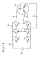
- FIG. 13 there is a control device that drives an AC motor 80 with a DC power supply 82 via a three-phase PWM inverter main circuit 81.
- a control device generates PWM waveforms Ea, Eb and Ec by level comparison between sine wave signals Va, Vb and Vc of each phase and a carrier wave signal C of a triangular wave as shown in FIG. 14 . Then, by applying the PWM waveforms, each switching element of the three-phase PWM inverter main circuit 81 is controlled in switching to obtain a sine wave output.
- reference characters Vab and Van refer to a line voltage and a phase voltage, respectively.
- a sine wave level and a phase are controlled to control an output current and a phase supplied from the three-phase PWM inverter main circuit 81 to a load such as an induction motor IM (AC motor) 80 or a permanent magnet motor (AC motor) not shown in Fig. 13 .
- IM AC motor
- AC motor permanent magnet motor
- an output current at three points P1 to P3 connecting the main circuit and the load is detected for three phases (or two phases) by a current sensor using a Hall CT.
- a general purpose inverter intended to reduce cost is demanded to reduce the number of current sensors.
- a method of providing only one current sensor on a DC side (point P4 in FIG. 13 ) of a PWM inverter and calculating an output current from the DC current.
- a voltage E of a DC power supply 82 of the PWM inverter is substantially constant, and thus an average value of detected DC currents changes in proportional to an output frequency of the inverter.
- the average value of the DC currents at low frequency is small, which reduces current detection accuracy to make it difficult to obtain high performance.
- Patent Document 1 discloses an output current detection device of a PWM inverter that uses the fact that current information (-Iw and Iu) of two phases: a minimum phase (Vw*) and a maximum phase (Vu*) of a voltage command value appear twice within a PWM carrier wave period in a DC input current IDC of a PWM inverter, samples a DC input current IDC based on PWM pulse signals (Pu, Pv and Pw), distributes the DC input current IDC for each phase, and detects three-phase current detection values (Iuc, Ivc and Iwc).
- Patent Document 2 discloses a control device and a control method for an AC motor and a module that automatically reduces carrier wave frequency of an inverter to increase a pulse width in the above-described case, and facilitates current detection.
- a control device for an AC motor that includes DC input current measuring means to a three-phase PWM inverter that drives the AC motor by inputting DC, and estimates a current to the AC motor from a measurement result of the DC input current measuring means to control the AC motor, including: an AC motor current detection unit that is connected to the DC input current measuring means and calculates each of three-phase currents in the AC motor; a three-phase voltage command calculation unit that calculates a three-phase voltage command provided to the AC motor from the three-phase currents calculated by the AC motor current detection unit; and a three-phase PWM waveform creation unit that has a carrier wave generation unit that generates carrier waves having a certain interval, and generates a three-phase PWM inverter control signal by level comparison between three-phase voltage reference signals of a U phase, a V phase and a W phase that constitute the three-phase voltage command calculated by the three-phase voltage command calculation unit and the carrier waves generated by the carrier wave generation unit, wherein the three-phase PWM inverter control
- the carrier waves having a certain interval are generated by the carrier wave generation unit, and the three-phase voltage reference signals of the U phase, the V phase and the W phase calculated by the three-phase voltage command calculation unit are compared with the carrier waves generated by the carrier wave generation unit.
- a plurality of, for example, two or three carrier waves have a certain interval. This prevents rising ends of a three-phase PWM signal from being close to each other to reduce a pulse width, prevents current detection from being made impossible, and allows current detection with high accuracy using an easy and simple configuration.
- the three-phase PWM inverter control signals are generated by level comparison between the carrier waves having a certain interval and the voltage reference signals of the U phase, the V phase and the W phase. This prevents rising ends of three-phase PWM signal from being close to each other to reduce a pulse width, and allows current detection.
- a ripple current (a harmonic current superimposed on a DC current) flowing through a DC bus of a circuit is increased.
- a capacitor 3 having a large capacity can be provided in a DC bus 2 for rectification, and thus there is little influence of a ripple current on the AC power supply 1.
- a compressor is driven by an engine.
- a compressor is driven by a motor (AC motor) rotated by a current supplied from an on-vehicle battery as a DC power supply.
- AC motor AC motor
- various devices are connected to the on-vehicle battery.
- the present invention is achieved in view of such technical problems, and has an object to provide an inverter control device for an AC motor and an electric compressor that can detect a three-phase AC motor current with high accuracy only with DC input current measuring means to a three-phase PWM inverter, and reduce resonance of a DC power supply by a ripple current in driving an AC motor with a DC current via a three-phase PWM inverter.
- the present invention provides an inverter control device for an AC motor that includes DC input current measuring means to a three-phase PWM inverter that drives the AC motor by inputting DC, and estimates a current supplied to the AC motor from a measurement result of the DC input current measuring means to control the AC motor, including: an AC motor current detection unit that is connected to the DC input current measuring means and calculates each of three-phase currents in the AC motor; a three-phase voltage command calculation unit that calculates a three-phase voltage command provided to the AC motor from the three-phase currents calculated by the AC motor current detection unit; and a three-phase PWM waveform creation unit that has a carrier wave generation unit that generates three carrier waves having a certain interval Ts, and generates a control signal of the three-phase PWM inverter by level comparison between three-phase voltage reference signals of a U phase, a V phase and a W phase that constitute the three-phase voltage command calculated by the three-phase voltage command calculation unit and the carrier waves generated by the carrier wave
- the DC current is thus detected to ensure a long sampling time.
- the present invention also provides an electric compressor including: a compressor that constitutes an air conditioner; a motor for driving the compressor; and a control device that controls an operation of the motor, wherein the control device includes DC input current measuring means to a three-phase PWM inverter that drives the motor by inputting DC, and estimates a current supplied to the motor from a measurement result of the DC input current measuring means to control the motor.
- the control device includes: a motor current detection unit that is connected to the DC input current measuring means and calculates each of three-phase currents in the motor; a three-phase voltage command calculation unit that calculates a three-phase voltage command provided to the motor from the three-phase currents calculated by the motor current detection unit; and a three-phase PWM waveform creation unit that has a carrier wave generation unit that generates three carrier waves having a certain interval Ts, and generates a control signal of the three-phase PWM inverter by level comparison between three-phase voltage reference signals of a U phase, a V phase and a W phase that constitute the three-phase voltage command calculated by the three-phase voltage command calculation unit and the carrier waves generated by the carrier wave generation unit, and the DC input current measuring means detects a DC current with a sampling time of the certain interval Ts or more for two phases among the U phase, the V phase and the W phase when the three carrier waves are increased and/or when the three carrier waves are reduced.
- the present invention also provides an electric compressor including: a compressor that constitutes an air conditioner; a motor for driving the compressor; and a control device that controls an operation of the motor, wherein the control device includes DC input current measuring means to a three-phase PWM inverter that drives the motor by inputting DC, and estimates a current supplied to the motor from a measurement result of the DC input current measuring means to control the motor.
- the control device includes: a motor current detection unit that is connected to the DC input current measuring means and calculates each of three-phase currents in the motor; a three-phase voltage command calculation unit that calculates a three-phase voltage command provided to the motor from the three-phase currents calculated by the motor current detection unit; a carrier wave generation unit that generates three carrier waves having a certain interval Ts; a three-phase PWM waveform creation unit that generates a control signal of the three-phase PWM inverter by level comparison between three-phase voltage reference signals of a U phase, a V phase and a W phase that constitute the three-phase voltage command calculated by the three-phase voltage command calculation unit and the carrier waves generated by the carrier wave generation unit, and the three-phase voltage command calculation unit changes the three-phase voltage reference signals of the U phase, the V phase and the W phase with time.
- Such an electric compressor changes the three-phase voltage reference signals with time to increase a sideband of the current, thereby spreading spectrum and reducing a ripple current.
- a sampling time sufficiently longer than the interval Ts of the carrier waves can be ensured, and the current can be easily detected.
- this reduces the sideband of the current flowing through a current sensor to concentrate spectrum. Then, frequency components of the current flowing through the DC input current measuring means are concentrated at a frequency of the carrier waves and n-fold thereof, thereby reducing frequency components around a resonance frequency on the side of the DC power supply, thereby reducing a ripple current. This can prevent resonance with the ripple current from causing trouble to other devices connected to the DC power supply.
- the three-phase voltage reference signals are changed with time to increase the sideband of the current, thereby spreading spectrum and reducing carrier frequency components.
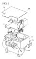
- FIG. 1 shows a configuration of an electric compressor (integral electric compressor) 100 according to an embodiment.
- a lower chamber 101a of a housing 101 houses a motor (AC motor) 10 (see FIG. 2 ) and a scroll compressor.
- a motor AC motor
- an upper chamber 101b opening upward of the housing 101 houses an inverter control device (control device) 11, and the upward opening of the upper chamber 101b is covered with a cover 102.
- FIG. 2 shows an electric circuit configuration of the electric compressor 100 shown in FIG. 1 .
- the inverter control device 11 controls supply of a current from a DC power supply 13 constituted by an on-vehicle battery to the motor 10 to operate the motor 10, and the motor 10 drives a scroll compressor. Then, a refrigerant is sucked into the housing 101 through a refrigerant suction port formed in an end of the lower chamber 101a on a side provided with the motor 10, and the refrigerant is compressed by the compressor. Then, the refrigerant compressed by the compressor is discharged through a refrigerant discharge port formed in an end on a side provided with the compressor.
- the inverter control device 11 includes a three-phase PWM inverter main circuit (three-phase PWM inverter) 12, a current sensor (DC input current measuring means) 14 constituted by shunt resistance that measures a current flowing from the DC power supply 13 to the three-phase PWM inverter main circuit 12, an AC motor current detection unit 15 that calculates three-phase currents of a U phase current, a V phase current, and a W phase current of the motor 10 from a measurement result of the current sensor 14, a three-phase voltage command calculation unit 16 that calculates a three-phase voltage command based on a calculation result of the AC motor current detection unit 15, and a three-phase PWM waveform creation unit 17 that creates a three-phase PWM waveform provided to the three-phase PWM inverter main circuit 12 by the three-phase voltage command from the three-phase voltage command calculation unit 16.
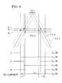
- FIG. 3 shows a configuration of the three-phase PWM waveform creation unit 17, and FIG. 4 is a timing chart for illustrating that a three-phase PWM signal is generated using three carrier waves Cry_e, Cry_m and Cry_l in the inverter control device 11.
- the three-phase PWM waveform creation unit 17 includes, as its configuration shown in FIG. 3 , three carrier wave generation units 20 that generate the three carrier waves Cry_e, Cry_m and Cry_l having a certain interval Ts as shown in FIG. 4 , a three-phase voltage reference signal generation unit 21 that generates different voltage reference signals Vu, Vv and Vw of three-phases (U phase, V phase, W phase) based on the three-phase voltage command calculated by the three-phase voltage command calculation unit 16, and a level comparison unit 22 that compares the three carrier waves Cry_e, Cry_m and Cry_l generated by the carrier wave generation unit 20 with the three-phase voltage reference signals generated by the three-phase voltage reference signal generation unit 21 to generate a three-phase PWM signal.
- the current sensor 14 measures the current flowing from the DC power supply 13 to the three-phase PWM inverter main circuit 12 and transmits the current to the AC motor current detection unit 15.
- the AC motor current detection unit 15 generates three-phase currents: a W-phase current iw, a U-phase current iu, and a V-phase current iv(iu-iw) from the transmitted current (for example, IDC) flowing through the three-phase PWM inverter main circuit 12, and the three-phase PWM signal shown in FIG. 4 transmitted from the three-phase PWM waveform creation unit 17 to the three-phase PWM inverter main circuit 12, and transmits the three-phase currents to the three-phase voltage command calculation unit 16.
- the three-phase voltage command calculation unit 16 generates three-phase voltage commands Vw*, Vu* and Vv* from the transmitted three-phase currents, and transmits the three-phase voltage commands to the three-phase PWM waveform creation unit 17.
- the three-phase voltage reference signal generation unit 21 From the three-phase voltage commands Vw*, Vu* and Vv* transmitted to the three-phase PWM waveform creation unit 17, the three-phase voltage reference signal generation unit 21 generates different voltage reference signals Vu, Vv and Vw of three-phases (U phase, V phase, W phase).
- the level comparison unit 22 compares the three-phase voltage reference signals Vu, Vv and Vw with the three carrier waves Cry_e, Cry_m and Cry_l generated by the carrier wave generation unit 20 to generate a three-phase PWM signal. Specifically, as shown in FIG.
- the three-phase voltage reference signals Vu, Vv and Vw are compared with the three carrier waves Cry_e, Cry_m and Cry_l generated by the carrier wave generation unit 20, and when a magnitude relation thereof changes, the signal is switched and transmitted to the three-phase PWM inverter main circuit 12.
- the three-phase PWM inverter main circuit 12 generates a new three-phase PWM signal from the transmitted three-phase PWM signal to estimate a current supplied to the motor 10, thereby driving the motor 10.
- the three-phase voltage reference signal generation unit 21 generates the three-phase voltage reference signals Vu, Vv and Vw as described below. Specifically, as shown in FIG. 4 , for the three-phase voltage reference signals Vu, Vv and Vw, the voltage reference signal Vv is in a maximum level, the voltage reference signal Vw is in a minimum level, and the voltage reference signal Vu is in an intermediate level between the voltage reference signals Vv and Vw.
- the carrier wave Cry_e at earliest timing is compared with the voltage reference signal Vu in the intermediate level
- the carrier wave Cry_l at latest timing is compared with the voltage reference signal Vw in the minimum level
- the carrier wave Cry_m at intermediate timing is compared with the voltage reference signal Vv in the maximum level.
- the carrier wave Cry_e earlier than that of the V phase is used to sample the U phase and the carrier wave Cry_l always later than that of the V phase is used to sample the W phase.
- the U phase can ensure a sampling time sufficiently longer than the interval Ts of the carrier waves Cry_e, Cry_m and Cry_l.
- the W phase can ensure a sampling time sufficiently longer than the interval Ts of the carrier waves Cry_e, Cry_m and Cry_l.
- the current can be easily detected.
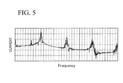
- frequency components of the current flowing through the current sensor 14 are concentrated at a frequency of the carrier waves and n-fold thereof. This reduces frequency components around a resonance frequency on the side of the DC power supply 13, and reduces a sideband of the current flowing through the current sensor 14 to concentrate spectrum, thereby reducing a ripple current. This can prevent resonance with the ripple current from causing trouble to other devices connected to the DC power supply 13.
- combinations are set of comparison between the three-phase voltage reference signals Vu, Vv and Vw and the three carrier waves Cry_e, Cry_m and Cry_l generated in order at the certain interval Ts, so that the U phase and the W phase can ensure the sampling time sufficiently longer than the interval Ts of the carrier waves Cry_e, Cry_m and Cry_l when the three carrier waves Cry_e, Cry_m and Cry_l are increased and when the carrier waves Cry_e, Cry_m and Cry_l are reduced, respectively.
- the combinations are not limited to those described above.
- a combination can be used in which the carrier wave Cry_e earlier than that of the W phase is used for sampling of the U phase, and the carrier wave Cry_l always later than that of the W phase is used to sample the V phase.
- a combination can be used in which the carrier wave Cry_e earlier than that of the U phase is used to sample the V phase, and the carrier wave Cry_l always later than that of the U phase is used to sample the W phase.
- FIG. 8 a combination can be used in which the carrier wave Cry_e earlier than that of the W phase is used to sample the V phase, and the carrier wave Cry_l always later than that of the W phase is used to sample the U phase.
- a combination can be used in which the carrier wave Cry_e earlier than that of the U phase is used to sample the W phase, and the carrier wave Cry_l always later than that of the U phase is used to sample the V phase.
- a combination can be used in which the carrier wave Cry_e earlier than that of the V phase is used to sample the W phase, and the carrier wave Cry_l always later than that of the V phase is used to sample the U phase.
- a sampling time sufficiently longer than the interval Ts of the carrier wave Cry_e, Cry_m and Cry_l can be ensured by changing the three-phase voltage reference signals Vu, Vv and Vw.
- levels of the three-phase voltage reference signals Vu, Vv and Vw are generally changed to detect the current while shifting timing of switching at random.
- the current is detected while the levels of the three-phase voltage reference signals Vu, Vv and Vw are increased or reduced by quasi-white noise such as an M-series signal with a difference between the phases being maintained.
- quasi-white noise such as an M-series signal with a difference between the phases being maintained.
- the timing of switching caused by comparison between the carrier waves Cry_e, Cry_m and Cry_l and the three-phase voltage reference signals Vu, Vv and Vw is changed at random.
- the inverter control device 11 outputs a line voltage, and no problem occurs even if a voltage command is moved up and down with the difference between the phases being maintained as shown in FIG. 11 .
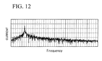
- FIG. 12 shows a result of switching during moving up and down of the carrier waves Cry_e, Cry_m and Cry_l while shifting the three-phase voltage reference signals Vu, Vv and Vw as described above.
- the sideband of the current flowing through the current sensor 14 was increased to spread spectrum, but the ripple current was increased as compared with that in FIG. 5 . It is supposed that the spectrum is spread not only to the sideband but also to the carrier wave components, and the components around the resonance frequency are generally increased.
- the integral electric compressor is described, but the compressor and the inverter control device 11 may be separately provided.
Landscapes
- Engineering & Computer Science (AREA)
- Power Engineering (AREA)
- Control Of Ac Motors In General (AREA)
- Inverter Devices (AREA)
Abstract
Description
- The present invention relates to an inverter control device for an AC motor and an electric compressor that detects a three-phase AC motor current with high accuracy using only DC input current measuring means to a three-phase PWM inverter in driving the AC motor with a DC current via the three-phase PWM inverter.
- As shown in
FIG. 13 , there is a control device that drives anAC motor 80 with aDC power supply 82 via a three-phase PWM invertermain circuit 81. Such a control device generates PWM waveforms Ea, Eb and Ec by level comparison between sine wave signals Va, Vb and Vc of each phase and a carrier wave signal C of a triangular wave as shown inFIG. 14 . Then, by applying the PWM waveforms, each switching element of the three-phase PWM invertermain circuit 81 is controlled in switching to obtain a sine wave output. InFIG. 14 , reference characters Vab and Van refer to a line voltage and a phase voltage, respectively. - A sine wave level and a phase are controlled to control an output current and a phase supplied from the three-phase PWM inverter
main circuit 81 to a load such as an induction motor IM (AC motor) 80 or a permanent magnet motor (AC motor) not shown inFig. 13 . In order to detect a current used for the control, in vector control, an output current at three points P1 to P3 connecting the main circuit and the load is detected for three phases (or two phases) by a current sensor using a Hall CT. - However, a general purpose inverter intended to reduce cost is demanded to reduce the number of current sensors. Thus, there is a method of providing only one current sensor on a DC side (point P4 in
FIG. 13 ) of a PWM inverter, and calculating an output current from the DC current. However, in this method, a voltage E of aDC power supply 82 of the PWM inverter is substantially constant, and thus an average value of detected DC currents changes in proportional to an output frequency of the inverter. Thus, the average value of the DC currents at low frequency is small, which reduces current detection accuracy to make it difficult to obtain high performance. - To address these problems, for example,
Patent Document 1 discloses an output current detection device of a PWM inverter that uses the fact that current information (-Iw and Iu) of two phases: a minimum phase (Vw*) and a maximum phase (Vu*) of a voltage command value appear twice within a PWM carrier wave period in a DC input current IDC of a PWM inverter, samples a DC input current IDC based on PWM pulse signals (Pu, Pv and Pw), distributes the DC input current IDC for each phase, and detects three-phase current detection values (Iuc, Ivc and Iwc). - However, in a current detection method disclosed in
Patent Document 1, for example, as shown inFIG. 15 , when an intermediate phase Vv of three-phase voltage command values Vu, Vv and Vw (corresponding to Va, Vb and Vc inFIG. 14 ) is close to a maximum phase Vu or a minimum phase Vw, or when an output voltage level is low, rising edges of a three-phase PWM signal are close to each other to reduce a pulse width, thereby making current detection impossible. Thus,Patent Document 2 discloses a control device and a control method for an AC motor and a module that automatically reduces carrier wave frequency of an inverter to increase a pulse width in the above-described case, and facilitates current detection. - However, in the method shown in
Patent Document 2, problems such as generation of noise or reduced efficiency that occurs when the entire carrier wave frequency is reduced can be solved, but the carrier wave frequency is reduced only when the intermediate phase of the voltage command values is close to the maximum or minimum phase, or when the output voltage level is low. Thus, the carrier wave frequency is reduced by software, which is considerably difficult. - Thus, the applicant has already proposed a control device for an AC motor as described below (see Patent Document 3).
- Specifically, there is proposed a control device for an AC motor that includes DC input current measuring means to a three-phase PWM inverter that drives the AC motor by inputting DC, and estimates a current to the AC motor from a measurement result of the DC input current measuring means to control the AC motor, including: an AC motor current detection unit that is connected to the DC input current measuring means and calculates each of three-phase currents in the AC motor; a three-phase voltage command calculation unit that calculates a three-phase voltage command provided to the AC motor from the three-phase currents calculated by the AC motor current detection unit; and a three-phase PWM waveform creation unit that has a carrier wave generation unit that generates carrier waves having a certain interval, and generates a three-phase PWM inverter control signal by level comparison between three-phase voltage reference signals of a U phase, a V phase and a W phase that constitute the three-phase voltage command calculated by the three-phase voltage command calculation unit and the carrier waves generated by the carrier wave generation unit, wherein the three-phase PWM inverter control signal is generated by level comparison between the three-phase voltage reference signals and the carrier waves.
- As such, the carrier waves having a certain interval are generated by the carrier wave generation unit, and the three-phase voltage reference signals of the U phase, the V phase and the W phase calculated by the three-phase voltage command calculation unit are compared with the carrier waves generated by the carrier wave generation unit. Thus, for example, even when an intermediate phase of voltage command values is close to a maximum or minimum value or when an output voltage level is low, a plurality of, for example, two or three carrier waves have a certain interval. This prevents rising ends of a three-phase PWM signal from being close to each other to reduce a pulse width, prevents current detection from being made impossible, and allows current detection with high accuracy using an easy and simple configuration.
-
- Patent Document 1: Japanese Patent Laid-Open No.
8-19263 - Patent Document 2: Japanese Patent Laid-Open No.
2005-45848 - Patent Document 3: Japanese Patent Laid-Open No.
2008-220117 - In the control device for an AC motor disclosed in
Patent Document 3 as described above, as shown inFIG. 16 , the three-phase PWM inverter control signals are generated by level comparison between the carrier waves having a certain interval and the voltage reference signals of the U phase, the V phase and the W phase.
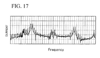
This prevents rising ends of three-phase PWM signal from being close to each other to reduce a pulse width, and allows current detection. On the other hand, as shown inFIG. 17 , a ripple current (a harmonic current superimposed on a DC current) flowing through a DC bus of a circuit is increased. - As shown in
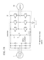
FIG. 18 , in a control device connected to anAC power supply 1 such as a commercial power supply, acapacitor 3 having a large capacity can be provided in aDC bus 2 for rectification, and thus there is little influence of a ripple current on theAC power supply 1. - On the other hand, as shown in
FIG. 19 , in a control device connected to aDC power supply 82, there is no need for rectification, and a capacitor 5 provided in aDC bus 2 has a small capacity, and thus a ripple current flows into theDC power supply 82. Then, if a resonance frequency on a side of theDC power supply 82 is close to a frequency of the ripple current, the side of theDC power supply 82 is resonated by the ripple current, which may cause trouble to other devices connected to theDC power supply 82. - Conventionally, in on-vehicle air conditioners, a compressor is driven by an engine. In recent years, in so-called hybrid vehicles or electric vehicles, a compressor is driven by a motor (AC motor) rotated by a current supplied from an on-vehicle battery as a DC power supply. When the motor of such an on-vehicle electric compressor is controlled by the control device having a configuration as shown in
FIG. 19 , various devices are connected to the on-vehicle battery. Thus, reducing resonance of the DC power supply by the ripple current is an important challenge. - Also, when the capacitor 5 cannot be provided in the configuration as shown in
FIG. 19 , a carrier frequency component is increased by an influence of the ripple current. - The present invention is achieved in view of such technical problems, and has an object to provide an inverter control device for an AC motor and an electric compressor that can detect a three-phase AC motor current with high accuracy only with DC input current measuring means to a three-phase PWM inverter, and reduce resonance of a DC power supply by a ripple current in driving an AC motor with a DC current via a three-phase PWM inverter.
- To achieve the above-described object, the present invention provides an inverter control device for an AC motor that includes DC input current measuring means to a three-phase PWM inverter that drives the AC motor by inputting DC, and estimates a current supplied to the AC motor from a measurement result of the DC input current measuring means to control the AC motor, including: an AC motor current detection unit that is connected to the DC input current measuring means and calculates each of three-phase currents in the AC motor; a three-phase voltage command calculation unit that calculates a three-phase voltage command provided to the AC motor from the three-phase currents calculated by the AC motor current detection unit; and a three-phase PWM waveform creation unit that has a carrier wave generation unit that generates three carrier waves having a certain interval Ts, and generates a control signal of the three-phase PWM inverter by level comparison between three-phase voltage reference signals of a U phase, a V phase and a W phase that constitute the three-phase voltage command calculated by the three-phase voltage command calculation unit and the carrier waves generated by the carrier wave generation unit. The DC input current measuring means detects a DC current with a sampling time of the certain interval Ts or more for two phases among the U phase, the V phase and the W phase when the three carrier waves are increased and/or when the three carrier waves are reduced.
- The DC current is thus detected to ensure a long sampling time.
- The present invention also provides an electric compressor including: a compressor that constitutes an air conditioner; a motor for driving the compressor; and a control device that controls an operation of the motor, wherein the control device includes DC input current measuring means to a three-phase PWM inverter that drives the motor by inputting DC, and estimates a current supplied to the motor from a measurement result of the DC input current measuring means to control the motor. The control device includes: a motor current detection unit that is connected to the DC input current measuring means and calculates each of three-phase currents in the motor; a three-phase voltage command calculation unit that calculates a three-phase voltage command provided to the motor from the three-phase currents calculated by the motor current detection unit; and a three-phase PWM waveform creation unit that has a carrier wave generation unit that generates three carrier waves having a certain interval Ts, and generates a control signal of the three-phase PWM inverter by level comparison between three-phase voltage reference signals of a U phase, a V phase and a W phase that constitute the three-phase voltage command calculated by the three-phase voltage command calculation unit and the carrier waves generated by the carrier wave generation unit, and the DC input current measuring means detects a DC current with a sampling time of the certain interval Ts or more for two phases among the U phase, the V phase and the W phase when the three carrier waves are increased and/or when the three carrier waves are reduced.
- The present invention also provides an electric compressor including: a compressor that constitutes an air conditioner; a motor for driving the compressor; and a control device that controls an operation of the motor, wherein the control device includes DC input current measuring means to a three-phase PWM inverter that drives the motor by inputting DC, and estimates a current supplied to the motor from a measurement result of the DC input current measuring means to control the motor. The control device includes: a motor current detection unit that is connected to the DC input current measuring means and calculates each of three-phase currents in the motor; a three-phase voltage command calculation unit that calculates a three-phase voltage command provided to the motor from the three-phase currents calculated by the motor current detection unit; a carrier wave generation unit that generates three carrier waves having a certain interval Ts; a three-phase PWM waveform creation unit that generates a control signal of the three-phase PWM inverter by level comparison between three-phase voltage reference signals of a U phase, a V phase and a W phase that constitute the three-phase voltage command calculated by the three-phase voltage command calculation unit and the carrier waves generated by the carrier wave generation unit, and the three-phase voltage command calculation unit changes the three-phase voltage reference signals of the U phase, the V phase and the W phase with time.
- Such an electric compressor changes the three-phase voltage reference signals with time to increase a sideband of the current, thereby spreading spectrum and reducing a ripple current.
- According to the present invention, a sampling time sufficiently longer than the interval Ts of the carrier waves can be ensured, and the current can be easily detected.
- Further, this reduces the sideband of the current flowing through a current sensor to concentrate spectrum. Then, frequency components of the current flowing through the DC input current measuring means are concentrated at a frequency of the carrier waves and n-fold thereof, thereby reducing frequency components around a resonance frequency on the side of the DC power supply, thereby reducing a ripple current. This can prevent resonance with the ripple current from causing trouble to other devices connected to the DC power supply.
- The three-phase voltage reference signals are changed with time to increase the sideband of the current, thereby spreading spectrum and reducing carrier frequency components.
-
- [
FIG. 1] FIG. 1 shows an example of an electric compressor according to an embodiment. - [
FIG. 2] FIG. 2 shows an electric circuit configuration of the electric compressor shown inFIG. 1 . - [
FIG. 3] FIG. 3 shows a functional configuration of a three-phase PWM waveform creation unit. - [
FIG. 4] FIG. 4 is a timing chart for illustrating that a three-phase PWM signal is generated using three carrier waves Cry_e, Cry_m and Cry_l in an inverter control device. - [
FIG. 5] FIG. 5 shows a frequency analysis result of a current when the three-phase PWM signal shown inFIG. 4 is used. - [
FIG. 6] FIG. 6 is a timing chart showing another example for illustrating that a three-phase PWM signal is generated using the three carrier waves Cry_e, Cry_m and Cry_l in the inverter control device. - [
FIG. 7] FIG. 7 is a timing chart showing a further example for illustrating that a three-phase PWM signal is generated using the three carrier waves Cry_e, Cry_m and Cry_l in the inverter control device. - [
FIG. 8] FIG. 8 is a timing chart showing a further example for illustrating that a three-phase PWM signal is generated using the three carrier waves Cry_e, Cry_m and Cry_l in the inverter control device. - [
FIG. 9] FIG. 9 is a timing chart showing a further example for illustrating that a three-phase PWM signal is generated using the three carrier waves Cry_e, Cry_m and Cry_l in the inverter control device. - [
FIG. 10] FIG. 10 is a timing chart showing a further example for illustrating that a three-phase PWM signal is generated using the three carrier waves Cry_e, Cry_m and Cry_l in the inverter control device. - [
FIG. 11] FIG. 11 is a timing chart for illustrating that a three-phase PWM signal is generated using three carrier waves Cry_e, Cry_m and Cry_l by a different method. - [
FIG. 12] FIG. 12 shows a frequency analysis result of a current when the three-phase PWM signal shown inFIG. 11 is used. - [
FIG. 13] FIG. 13 shows a circuit configuration of a conventional inverter control device for an AC motor. - [
FIG. 14] FIG. 14 is a timing chart showing a driving waveform in a conventional control device for an AC motor using a three-phase PWM inverter. - [
FIG. 15] FIG. 15 is a timing chart for illustrating a phenomenon in which with one carrier wave in a conventional control device for an AC motor, a current cannot be detected if an intermediate phase of voltage command values is close to a maximum or minimum phase or an output voltage level is low. - [
FIG. 16] FIG. 16 shows a conventional relationship between three carrier waves and three-phase voltage reference signals and a three-phase PWM signal generated thereby. - [
FIG. 17] FIG. 17 shows a frequency analysis result of a current when the three-phase PWM signal shown inFIG. 16 is used. - [
FIG. 18] FIG. 18 shows a circuit configuration of an inverter control device when a power supply is AC. - [
FIG. 19] FIG. 19 shows a circuit configuration of an inverter control device when a power supply is DC. - Now, the present invention will be described in detail based on an embodiment shown in the accompanying drawings.
-
FIG. 1 shows a configuration of an electric compressor (integral electric compressor) 100 according to an embodiment. - As shown in
FIG. 1 , in anelectric compressor 100, alower chamber 101a of ahousing 101 houses a motor (AC motor) 10 (seeFIG. 2 ) and a scroll compressor. Further, in theelectric compressor 100, anupper chamber 101b opening upward of thehousing 101 houses an inverter control device (control device) 11, and the upward opening of theupper chamber 101b is covered with acover 102. -
FIG. 2 shows an electric circuit configuration of theelectric compressor 100 shown inFIG. 1 . - As shown in
FIG. 2 , in theelectric compressor 100, theinverter control device 11 controls supply of a current from aDC power supply 13 constituted by an on-vehicle battery to themotor 10 to operate themotor 10, and themotor 10 drives a scroll compressor. Then, a refrigerant is sucked into thehousing 101 through a refrigerant suction port formed in an end of thelower chamber 101a on a side provided with themotor 10, and the refrigerant is compressed by the compressor. Then, the refrigerant compressed by the compressor is discharged through a refrigerant discharge port formed in an end on a side provided with the compressor. - The
inverter control device 11 includes a three-phase PWM inverter main circuit (three-phase PWM inverter) 12, a current sensor (DC input current measuring means) 14 constituted by shunt resistance that measures a current flowing from theDC power supply 13 to the three-phase PWM invertermain circuit 12, an AC motorcurrent detection unit 15 that calculates three-phase currents of a U phase current, a V phase current, and a W phase current of themotor 10 from a measurement result of thecurrent sensor 14, a three-phase voltagecommand calculation unit 16 that calculates a three-phase voltage command based on a calculation result of the AC motorcurrent detection unit 15, and a three-phase PWMwaveform creation unit 17 that creates a three-phase PWM waveform provided to the three-phase PWM invertermain circuit 12 by the three-phase voltage command from the three-phase voltagecommand calculation unit 16. -
FIG. 3 shows a configuration of the three-phase PWMwaveform creation unit 17, andFIG. 4 is a timing chart for illustrating that a three-phase PWM signal is generated using three carrier waves Cry_e, Cry_m and Cry_l in theinverter control device 11. - The three-phase PWM
waveform creation unit 17 includes, as its configuration shown inFIG. 3 , three carrierwave generation units 20 that generate the three carrier waves Cry_e, Cry_m and Cry_l having a certain interval Ts as shown inFIG. 4 , a three-phase voltage referencesignal generation unit 21 that generates different voltage reference signals Vu, Vv and Vw of three-phases (U phase, V phase, W phase) based on the three-phase voltage command calculated by the three-phase voltagecommand calculation unit 16, and alevel comparison unit 22 that compares the three carrier waves Cry_e, Cry_m and Cry_l generated by the carrierwave generation unit 20 with the three-phase voltage reference signals generated by the three-phase voltage referencesignal generation unit 21 to generate a three-phase PWM signal. - An operation of the
inverter control device 11 will be described. Thecurrent sensor 14 measures the current flowing from theDC power supply 13 to the three-phase PWM invertermain circuit 12 and transmits the current to the AC motorcurrent detection unit 15. The AC motorcurrent detection unit 15 generates three-phase currents: a W-phase current iw, a U-phase current iu, and a V-phase current iv(iu-iw) from the transmitted current (for example, IDC) flowing through the three-phase PWM invertermain circuit 12, and the three-phase PWM signal shown inFIG. 4 transmitted from the three-phase PWMwaveform creation unit 17 to the three-phase PWM invertermain circuit 12, and transmits the three-phase currents to the three-phase voltagecommand calculation unit 16. - Then, the three-phase voltage
command calculation unit 16 generates three-phase voltage commands Vw*, Vu* and Vv* from the transmitted three-phase currents, and transmits the three-phase voltage commands to the three-phase PWMwaveform creation unit 17. - From the three-phase voltage commands Vw*, Vu* and Vv* transmitted to the three-phase PWM
waveform creation unit 17, the three-phase voltage referencesignal generation unit 21 generates different voltage reference signals Vu, Vv and Vw of three-phases (U phase, V phase, W phase). Thelevel comparison unit 22 compares the three-phase voltage reference signals Vu, Vv and Vw with the three carrier waves Cry_e, Cry_m and Cry_l generated by the carrierwave generation unit 20 to generate a three-phase PWM signal. Specifically, as shown inFIG. 4 , the three-phase voltage reference signals Vu, Vv and Vw are compared with the three carrier waves Cry_e, Cry_m and Cry_l generated by the carrierwave generation unit 20, and when a magnitude relation thereof changes, the signal is switched and transmitted to the three-phase PWM invertermain circuit 12. Thus, the three-phase PWM invertermain circuit 12 generates a new three-phase PWM signal from the transmitted three-phase PWM signal to estimate a current supplied to themotor 10, thereby driving themotor 10. - In this embodiment, the three-phase voltage reference
signal generation unit 21 generates the three-phase voltage reference signals Vu, Vv and Vw as described below. Specifically, as shown inFIG. 4 , for the three-phase voltage reference signals Vu, Vv and Vw, the voltage reference signal Vv is in a maximum level, the voltage reference signal Vw is in a minimum level, and the voltage reference signal Vu is in an intermediate level between the voltage reference signals Vv and Vw. - For the three carrier waves Cry_e, Cry_m and Cry_l generated in order at a certain interval Ts by the carrier
wave generation unit 20, the carrier wave Cry_e at earliest timing is compared with the voltage reference signal Vu in the intermediate level, the carrier wave Cry_l at latest timing is compared with the voltage reference signal Vw in the minimum level, and the carrier wave Cry_m at intermediate timing is compared with the voltage reference signal Vv in the maximum level. - As such, the carrier wave Cry_e earlier than that of the V phase is used to sample the U phase and the carrier wave Cry_l always later than that of the V phase is used to sample the W phase. Thus, when the three carrier waves Cry_e, Cry_m and Cry_l are increased, the U phase can ensure a sampling time sufficiently longer than the interval Ts of the carrier waves Cry_e, Cry_m and Cry_l. When the carrier waves Cry_e, Cry_m and Cry_l are reduced, the W phase can ensure a sampling time sufficiently longer than the interval Ts of the carrier waves Cry_e, Cry_m and Cry_l. Thus, the current can be easily detected.
- Thus, as shown in
FIG. 5 , frequency components of the current flowing through thecurrent sensor 14 are concentrated at a frequency of the carrier waves and n-fold thereof. This reduces frequency components around a resonance frequency on the side of theDC power supply 13, and reduces a sideband of the current flowing through thecurrent sensor 14 to concentrate spectrum, thereby reducing a ripple current. This can prevent resonance with the ripple current from causing trouble to other devices connected to theDC power supply 13. - In the embodiment, combinations are set of comparison between the three-phase voltage reference signals Vu, Vv and Vw and the three carrier waves Cry_e, Cry_m and Cry_l generated in order at the certain interval Ts, so that the U phase and the W phase can ensure the sampling time sufficiently longer than the interval Ts of the carrier waves Cry_e, Cry_m and Cry_l when the three carrier waves Cry_e, Cry_m and Cry_l are increased and when the carrier waves Cry_e, Cry_m and Cry_l are reduced, respectively. However, the combinations are not limited to those described above.
- As shown in
FIG. 6 , a combination can be used in which the carrier wave Cry_e earlier than that of the W phase is used for sampling of the U phase, and the carrier wave Cry_l always later than that of the W phase is used to sample the V phase. Also, as shown inFIG. 7 , a combination can be used in which the carrier wave Cry_e earlier than that of the U phase is used to sample the V phase, and the carrier wave Cry_l always later than that of the U phase is used to sample the W phase. Also, as shown inFIG. 8 , a combination can be used in which the carrier wave Cry_e earlier than that of the W phase is used to sample the V phase, and the carrier wave Cry_l always later than that of the W phase is used to sample the U phase. Also, as shown inFIG. 9 , a combination can be used in which the carrier wave Cry_e earlier than that of the U phase is used to sample the W phase, and the carrier wave Cry_l always later than that of the U phase is used to sample the V phase. Also, as shown inFIG.10 , a combination can be used in which the carrier wave Cry_e earlier than that of the V phase is used to sample the W phase, and the carrier wave Cry_l always later than that of the V phase is used to sample the U phase. - In the example shown in
FIGS. 6 to 10 , when the three carrier waves Cry_e, Cry_m and Cry_l are increased and/or when the carrier waves Cry_e, Cry_m and Cry_l are reduced, a sampling time sufficiently longer than the interval Ts of the carrier wave Cry_e, Cry_m and Cry_l can be ensured for two phases among the U phase, the V phase and the W phase, and the current can be easily detected. - Instead of ensuring a sampling time sufficiently longer than the interval Ts of the carrier wave Cry_e, Cry_m and Cry_l by the combinations of the comparison between the three-phase voltage reference signals Vu, Vv and Vw and the three carrier waves Cry_e, Cry_m and Cry_l generated in order at the certain interval Ts, a sampling time sufficiently longer than the interval Ts of the carrier wave Cry_e, Cry_m and Cry_l can be ensured by changing the three-phase voltage reference signals Vu, Vv and Vw.
- Specifically, as shown in
FIGS. 11A and11B , levels of the three-phase voltage reference signals Vu, Vv and Vw are generally changed to detect the current while shifting timing of switching at random. The current is detected while the levels of the three-phase voltage reference signals Vu, Vv and Vw are increased or reduced by quasi-white noise such as an M-series signal with a difference between the phases being maintained. Then, the timing of switching caused by comparison between the carrier waves Cry_e, Cry_m and Cry_l and the three-phase voltage reference signals Vu, Vv and Vw is changed at random. - At this time, the
inverter control device 11 outputs a line voltage, and no problem occurs even if a voltage command is moved up and down with the difference between the phases being maintained as shown inFIG. 11 . -
FIG. 12 shows a result of switching during moving up and down of the carrier waves Cry_e, Cry_m and Cry_l while shifting the three-phase voltage reference signals Vu, Vv and Vw as described above. - As shown in
FIG. 12 , the sideband of the current flowing through thecurrent sensor 14 was increased to spread spectrum, but the ripple current was increased as compared with that inFIG. 5 . It is supposed that the spectrum is spread not only to the sideband but also to the carrier wave components, and the components around the resonance frequency are generally increased. - In the embodiment, the integral electric compressor is described, but the compressor and the
inverter control device 11 may be separately provided. - Further, the configurations described in the embodiment may be chosen or changed to other configurations without departing from the gist of the present invention.
-
- 10 motor (AC motor)
- 11 inverter control device (control device)
- 12 three-phase PWM inverter main circuit (three-phase PWM inverter)
- 13 DC power supply
- 14 current sensor (DC input current measuring means)
- 15 AC motor current detection unit
- 16 three-phase voltage command calculation unit
- 17 three-phase PWM
waveform creation unit 20 carrier wave generation unit - 21 three-phase voltage reference signal generation unit
- 22 level comparison unit
- 100 electric compressor
- 101 housing
Claims (4)
- An inverter control device for an AC motor that includes DC input current measuring means to a three-phase PWM inverter that drives the AC motor by inputting DC, and estimates a current supplied to the AC motor from a measurement result of the DC input current measuring means to control the AC motor, comprising:an AC motor current detection unit that is connected to the DC input current measuring means and calculates each of three-phase currents in the AC motor;a three-phase voltage command calculation unit that calculates a three-phase voltage command provided to the AC motor from the three-phase currents calculated by the AC motor current detection unit; anda three-phase PWM waveform creation unit that has a carrier wave generation unit that generates three carrier waves having a certain interval Ts, and generates a control signal of the three-phase PWM inverter by level comparison between three-phase voltage reference signals of a U phase, a V phase and a W phase that constitute the three-phase voltage command calculated by the three-phase voltage command calculation unit and the carrier waves generated by the carrier wave generation unit,wherein the DC input current measuring means detects a DC current with a sampling time of the certain interval Ts or more for two phases among the U phase, the V phase and the W phase when the three carrier waves are increased and/or when the three carrier waves are reduced.
- An electric compressor comprising:a compressor that constitutes an air conditioner;a motor for driving the compressor; anda control device that controls an operation of the motor,wherein the control device includes DC input current measuring means to a three-phase PWM inverter that drives the motor by inputting DC, and estimates a current supplied to the motor from a measurement result of the DC input current measuring means to control the motor,the control device includes:a motor current detection unit that is connected to the DC input current measuring means and calculates each of three-phase currents in the motor;a three-phase voltage command calculation unit that calculates a three-phase voltage command provided to the motor from the three-phase currents calculated by the motor current detection unit; anda three-phase PWM waveform creation unit that has a carrier wave generation unit that generates three carrier waves having a certain interval Ts, and generates a control signal of the three-phase PWM inverter by level comparison between three-phase voltage reference signals of a U phase, a V phase and a W phase that constitute the three-phase voltage command calculated by the three-phase voltage command calculation unit and the carrier waves generated by the carrier wave generation unit, andthe DC input current measuring means detects a DC current with a sampling time of the certain interval Ts or more for two phases among the U phase, the V phase and the W phase when the three carrier waves are increased and/or when the three carrier waves are reduced.
- An electric compressor comprising:a compressor that constitutes an air conditioner;a motor for driving the compressor; anda control device that controls an operation of the motor,wherein the control device includes DC input current measuring means to a three-phase PWM inverter that drives the motor by inputting DC, and estimates a current supplied to the motor from a measurement result of the DC input current measuring means to control the motor,the control device includes:a motor current detection unit that is connected to the DC input current measuring means and calculates each of three-phase currents in the motor;a three-phase voltage command calculation unit that calculates a three-phase voltage command provided to the motor from the three-phase currents calculated by the motor current detection unit;a carrier wave generation unit that generates three carrier waves having a certain interval Ts;a three-phase PWM waveform creation unit that generates a control signal of the three-phase PWM inverter by level comparison between three-phase voltage reference signals of a U phase, a V phase and a W phase that constitute the three-phase voltage command calculated by the three-phase voltage command calculation unit and the carrier waves generated by the carrier wave generation unit, andthe three-phase voltage command calculation unit changes the three-phase voltage reference signals of the U phase, the V phase and the W phase with time.
- The electric compressor according to claim 3,
wherein the DC input current measuring means detects a DC current with a sampling time of the certain interval Ts or more for two phases among the U phase, the V phase and the W phase when the three carrier waves are increased and/or when the three carrier waves are reduced.
Applications Claiming Priority (2)
| Application Number | Priority Date | Filing Date | Title |
|---|---|---|---|
| JP2009037197A JP5535493B2 (en) | 2009-02-19 | 2009-02-19 | In-vehicle electric compressor |
| PCT/JP2010/001062 WO2010095445A1 (en) | 2009-02-19 | 2010-02-18 | Inverter control device and electric compressor for ac motor |
Publications (3)
| Publication Number | Publication Date |
|---|---|
| EP2400657A1 true EP2400657A1 (en) | 2011-12-28 |
| EP2400657A4 EP2400657A4 (en) | 2017-02-01 |
| EP2400657B1 EP2400657B1 (en) | 2019-03-27 |
Family
ID=42633732
Family Applications (1)
| Application Number | Title | Priority Date | Filing Date |
|---|---|---|---|
| EP10743574.5A Active EP2400657B1 (en) | 2009-02-19 | 2010-02-18 | Inverter control device for an electric compressor motor |
Country Status (4)
| Country | Link |
|---|---|
| US (1) | US8598821B2 (en) |
| EP (1) | EP2400657B1 (en) |
| JP (1) | JP5535493B2 (en) |
| WO (1) | WO2010095445A1 (en) |
Cited By (1)
| Publication number | Priority date | Publication date | Assignee | Title |
|---|---|---|---|---|
| CN109964394A (en) * | 2016-11-18 | 2019-07-02 | 阿洛斯电子公司 | DC bus ripple cancellation for multiphase motors |
Families Citing this family (12)
| Publication number | Priority date | Publication date | Assignee | Title |
|---|---|---|---|---|
| JP5776199B2 (en) * | 2011-02-09 | 2015-09-09 | ダイキン工業株式会社 | Inverter control method |
| JP5693714B2 (en) * | 2011-04-28 | 2015-04-01 | 三菱電機株式会社 | HEAT PUMP DEVICE, HEAT PUMP SYSTEM, AND INVERTER CONTROL METHOD |
| JP5906971B2 (en) * | 2012-07-03 | 2016-04-20 | 株式会社デンソー | Motor drive device |
| CN104121173B (en) * | 2013-04-23 | 2016-02-17 | 广东美的制冷设备有限公司 | A kind of controlling method of compressor of air-conditioning and control gear |
| JP2015006061A (en) * | 2013-06-20 | 2015-01-08 | 株式会社豊田自動織機 | On-vehicle motor compressor |
| JP6369852B2 (en) * | 2014-03-04 | 2018-08-08 | 三菱重工サーマルシステムズ株式会社 | Inverter control device and inverter device |
| JP6341165B2 (en) * | 2015-09-01 | 2018-06-13 | 株式会社安川電機 | Power conversion device, phase current detection device, and phase current detection method |
| JP6665669B2 (en) * | 2016-05-09 | 2020-03-13 | 株式会社デンソー | Power converter |
| JP6812958B2 (en) * | 2017-11-30 | 2021-01-13 | 株式会社豊田自動織機 | In-vehicle electric compressor |
| US11329594B2 (en) * | 2019-10-10 | 2022-05-10 | Samsung Electronics Co., Ltd. | Apparatus and control method for reducing leakage current and noise |
| JP2022116751A (en) | 2021-01-29 | 2022-08-10 | 株式会社豊田自動織機 | Motor compressor |
| CN116582992A (en) * | 2023-06-14 | 2023-08-11 | 上海联影医疗科技股份有限公司 | A control method of a high-voltage generator and a high-voltage generator |
Family Cites Families (10)
| Publication number | Priority date | Publication date | Assignee | Title |
|---|---|---|---|---|
| JPH0819263A (en) | 1994-06-30 | 1996-01-19 | Meidensha Corp | Output current detector of pwm inverter |
| JP3818137B2 (en) * | 2001-11-27 | 2006-09-06 | 株式会社豊田自動織機 | Air conditioner |
| JP4045105B2 (en) * | 2002-01-30 | 2008-02-13 | 株式会社日立産機システム | Pulse width modulation method, power conversion device, and inverter device |
| JP2004064903A (en) * | 2002-07-30 | 2004-02-26 | Hitachi Ltd | Synchronous motor control device and device using the same |
| JP3951975B2 (en) | 2003-07-22 | 2007-08-01 | 株式会社日立製作所 | AC motor control device, AC motor control method and module |
| US7049778B2 (en) * | 2004-02-09 | 2006-05-23 | Nippon Yusoki Co., Ltd. | Inverter control apparatus and inverter control method |
| JP2006246649A (en) * | 2005-03-04 | 2006-09-14 | Toshiba Corp | Inverter device |
| JP2008067556A (en) * | 2006-09-11 | 2008-03-21 | Sanyo Electric Co Ltd | Motor controller |
| JP4120694B1 (en) * | 2007-01-09 | 2008-07-16 | ダイキン工業株式会社 | Inverter compressor operation method and compressor drive device |
| JP2008220117A (en) * | 2007-03-07 | 2008-09-18 | Mitsubishi Heavy Ind Ltd | Ac motor controller |
-
2009
- 2009-02-19 JP JP2009037197A patent/JP5535493B2/en not_active Expired - Fee Related
-
2010
- 2010-02-18 EP EP10743574.5A patent/EP2400657B1/en active Active
- 2010-02-18 US US13/127,613 patent/US8598821B2/en not_active Expired - Fee Related
- 2010-02-18 WO PCT/JP2010/001062 patent/WO2010095445A1/en not_active Ceased
Non-Patent Citations (1)
| Title |
|---|
| See references of WO2010095445A1 * |
Cited By (2)
| Publication number | Priority date | Publication date | Assignee | Title |
|---|---|---|---|---|
| CN109964394A (en) * | 2016-11-18 | 2019-07-02 | 阿洛斯电子公司 | DC bus ripple cancellation for multiphase motors |
| CN109964394B (en) * | 2016-11-18 | 2021-07-20 | 阿洛斯电子公司 | DC bus ripple cancellation for multiphase motors |
Also Published As
| Publication number | Publication date |
|---|---|
| JP5535493B2 (en) | 2014-07-02 |
| EP2400657A4 (en) | 2017-02-01 |
| US8598821B2 (en) | 2013-12-03 |
| EP2400657B1 (en) | 2019-03-27 |
| WO2010095445A1 (en) | 2010-08-26 |
| JP2010193668A (en) | 2010-09-02 |
| US20110243757A1 (en) | 2011-10-06 |
Similar Documents
| Publication | Publication Date | Title |
|---|---|---|
| US8598821B2 (en) | Inverter control device for AC motor and electric compressor | |
| US9325274B2 (en) | Apparatus for carrying out improved control of rotary machine | |
| JP5119222B2 (en) | Converter device, motor driving module, and refrigeration device | |
| EP2333948A2 (en) | Inverter control device and motor drive system | |
| EP2779433B1 (en) | Motor drive device | |
| EP3422551A1 (en) | Power conversion device, motor drive device, and refrigerator using same | |
| EP2605399A1 (en) | Motor drive system and control method thereof | |
| KR102493847B1 (en) | Motor driving apparatus and home appliance including the same | |
| JP6953763B2 (en) | Motor control device | |
| EP2755319B1 (en) | Control system for synchronous motor | |
| CN1973426A (en) | Inverter device and vehicle air conditioner using the same | |
| CN103141022B (en) | Control device for inverter and inverter control method | |
| EP3806320B1 (en) | Permanent-magnet synchronous motor and ventilation blower | |
| JP2002300800A (en) | Power converter | |
| JP5196269B2 (en) | Electric motor control device | |
| JP2010068581A (en) | Electric motor drive unit | |
| WO2013018611A1 (en) | Synchronous motor driving device and device equipped with same and having a refrigeration cycle | |
| JP2006230049A (en) | Motor control device and motor current detection device | |
| EP3979485A1 (en) | Power conversion device | |
| JP2010200395A (en) | Driver and apparatus for motor | |
| CN107449962A (en) | Compressor and its power estimating method and device | |
| CN109546866B (en) | Air conditioning system, variable frequency controller and alternating current estimation method and device thereof | |
| JP2010259181A (en) | Electric motor control device | |
| JP5317812B2 (en) | Electric motor control device | |
| JP4793079B2 (en) | Inverter controller for motor drive |
Legal Events
| Date | Code | Title | Description |
|---|---|---|---|
| PUAI | Public reference made under article 153(3) epc to a published international application that has entered the european phase |
Free format text: ORIGINAL CODE: 0009012 |
|
| 17P | Request for examination filed |
Effective date: 20110503 |
|
| AK | Designated contracting states |
Kind code of ref document: A1 Designated state(s): AT BE BG CH CY CZ DE DK EE ES FI FR GB GR HR HU IE IS IT LI LT LU LV MC MK MT NL NO PL PT RO SE SI SK SM TR |
|
| DAX | Request for extension of the european patent (deleted) | ||
| RA4 | Supplementary search report drawn up and despatched (corrected) |
Effective date: 20170105 |
|
| RIC1 | Information provided on ipc code assigned before grant |
Ipc: H02M 7/5395 20060101ALI20161223BHEP Ipc: H02M 7/48 20070101ALI20161223BHEP Ipc: H02P 27/06 20060101AFI20161223BHEP Ipc: H02M 7/5387 20070101ALI20161223BHEP Ipc: H02M 1/00 20070101ALI20161223BHEP |
|
| REG | Reference to a national code |
Ref country code: DE Ref legal event code: R079 Ref document number: 602010057831 Country of ref document: DE Free format text: PREVIOUS MAIN CLASS: H02P0027060000 Ipc: H02P0027080000 |
|
| GRAP | Despatch of communication of intention to grant a patent |
Free format text: ORIGINAL CODE: EPIDOSNIGR1 |
|
| STAA | Information on the status of an ep patent application or granted ep patent |
Free format text: STATUS: GRANT OF PATENT IS INTENDED |
|
| RIC1 | Information provided on ipc code assigned before grant |
Ipc: H02M 7/5387 20070101ALI20180817BHEP Ipc: H02M 7/5395 20060101ALI20180817BHEP Ipc: H02P 27/08 20060101AFI20180817BHEP Ipc: H02M 1/00 20060101ALI20180817BHEP |
|
| INTG | Intention to grant announced |
Effective date: 20180918 |
|
| GRAS | Grant fee paid |
Free format text: ORIGINAL CODE: EPIDOSNIGR3 |
|
| GRAA | (expected) grant |
Free format text: ORIGINAL CODE: 0009210 |
|
| STAA | Information on the status of an ep patent application or granted ep patent |
Free format text: STATUS: THE PATENT HAS BEEN GRANTED |
|
| AK | Designated contracting states |
Kind code of ref document: B1 Designated state(s): AT BE BG CH CY CZ DE DK EE ES FI FR GB GR HR HU IE IS IT LI LT LU LV MC MK MT NL NO PL PT RO SE SI SK SM TR |
|
| REG | Reference to a national code |
Ref country code: GB Ref legal event code: FG4D |
|
| REG | Reference to a national code |
Ref country code: CH Ref legal event code: EP |
|
| REG | Reference to a national code |
Ref country code: AT Ref legal event code: REF Ref document number: 1114228 Country of ref document: AT Kind code of ref document: T Effective date: 20190415 |
|
| REG | Reference to a national code |
Ref country code: IE Ref legal event code: FG4D |
|
| REG | Reference to a national code |
Ref country code: DE Ref legal event code: R096 Ref document number: 602010057831 Country of ref document: DE |
|
| PG25 | Lapsed in a contracting state [announced via postgrant information from national office to epo] |
Ref country code: SE Free format text: LAPSE BECAUSE OF FAILURE TO SUBMIT A TRANSLATION OF THE DESCRIPTION OR TO PAY THE FEE WITHIN THE PRESCRIBED TIME-LIMIT Effective date: 20190327 Ref country code: FI Free format text: LAPSE BECAUSE OF FAILURE TO SUBMIT A TRANSLATION OF THE DESCRIPTION OR TO PAY THE FEE WITHIN THE PRESCRIBED TIME-LIMIT Effective date: 20190327 Ref country code: NO Free format text: LAPSE BECAUSE OF FAILURE TO SUBMIT A TRANSLATION OF THE DESCRIPTION OR TO PAY THE FEE WITHIN THE PRESCRIBED TIME-LIMIT Effective date: 20190627 Ref country code: LT Free format text: LAPSE BECAUSE OF FAILURE TO SUBMIT A TRANSLATION OF THE DESCRIPTION OR TO PAY THE FEE WITHIN THE PRESCRIBED TIME-LIMIT Effective date: 20190327 |
|
| REG | Reference to a national code |
Ref country code: NL Ref legal event code: MP Effective date: 20190327 |
|
| PG25 | Lapsed in a contracting state [announced via postgrant information from national office to epo] |
Ref country code: GR Free format text: LAPSE BECAUSE OF FAILURE TO SUBMIT A TRANSLATION OF THE DESCRIPTION OR TO PAY THE FEE WITHIN THE PRESCRIBED TIME-LIMIT Effective date: 20190628 Ref country code: HR Free format text: LAPSE BECAUSE OF FAILURE TO SUBMIT A TRANSLATION OF THE DESCRIPTION OR TO PAY THE FEE WITHIN THE PRESCRIBED TIME-LIMIT Effective date: 20190327 Ref country code: LV Free format text: LAPSE BECAUSE OF FAILURE TO SUBMIT A TRANSLATION OF THE DESCRIPTION OR TO PAY THE FEE WITHIN THE PRESCRIBED TIME-LIMIT Effective date: 20190327 Ref country code: NL Free format text: LAPSE BECAUSE OF FAILURE TO SUBMIT A TRANSLATION OF THE DESCRIPTION OR TO PAY THE FEE WITHIN THE PRESCRIBED TIME-LIMIT Effective date: 20190327 Ref country code: BG Free format text: LAPSE BECAUSE OF FAILURE TO SUBMIT A TRANSLATION OF THE DESCRIPTION OR TO PAY THE FEE WITHIN THE PRESCRIBED TIME-LIMIT Effective date: 20190627 |
|
| REG | Reference to a national code |
Ref country code: AT Ref legal event code: MK05 Ref document number: 1114228 Country of ref document: AT Kind code of ref document: T Effective date: 20190327 |
|
| PG25 | Lapsed in a contracting state [announced via postgrant information from national office to epo] |
Ref country code: IT Free format text: LAPSE BECAUSE OF FAILURE TO SUBMIT A TRANSLATION OF THE DESCRIPTION OR TO PAY THE FEE WITHIN THE PRESCRIBED TIME-LIMIT Effective date: 20190327 Ref country code: ES Free format text: LAPSE BECAUSE OF FAILURE TO SUBMIT A TRANSLATION OF THE DESCRIPTION OR TO PAY THE FEE WITHIN THE PRESCRIBED TIME-LIMIT Effective date: 20190327 Ref country code: CZ Free format text: LAPSE BECAUSE OF FAILURE TO SUBMIT A TRANSLATION OF THE DESCRIPTION OR TO PAY THE FEE WITHIN THE PRESCRIBED TIME-LIMIT Effective date: 20190327 Ref country code: RO Free format text: LAPSE BECAUSE OF FAILURE TO SUBMIT A TRANSLATION OF THE DESCRIPTION OR TO PAY THE FEE WITHIN THE PRESCRIBED TIME-LIMIT Effective date: 20190327 Ref country code: EE Free format text: LAPSE BECAUSE OF FAILURE TO SUBMIT A TRANSLATION OF THE DESCRIPTION OR TO PAY THE FEE WITHIN THE PRESCRIBED TIME-LIMIT Effective date: 20190327 Ref country code: SK Free format text: LAPSE BECAUSE OF FAILURE TO SUBMIT A TRANSLATION OF THE DESCRIPTION OR TO PAY THE FEE WITHIN THE PRESCRIBED TIME-LIMIT Effective date: 20190327 Ref country code: PT Free format text: LAPSE BECAUSE OF FAILURE TO SUBMIT A TRANSLATION OF THE DESCRIPTION OR TO PAY THE FEE WITHIN THE PRESCRIBED TIME-LIMIT Effective date: 20190727 |
|
| PG25 | Lapsed in a contracting state [announced via postgrant information from national office to epo] |
Ref country code: PL Free format text: LAPSE BECAUSE OF FAILURE TO SUBMIT A TRANSLATION OF THE DESCRIPTION OR TO PAY THE FEE WITHIN THE PRESCRIBED TIME-LIMIT Effective date: 20190327 Ref country code: SM Free format text: LAPSE BECAUSE OF FAILURE TO SUBMIT A TRANSLATION OF THE DESCRIPTION OR TO PAY THE FEE WITHIN THE PRESCRIBED TIME-LIMIT Effective date: 20190327 |
|
| PG25 | Lapsed in a contracting state [announced via postgrant information from national office to epo] |
Ref country code: IS Free format text: LAPSE BECAUSE OF FAILURE TO SUBMIT A TRANSLATION OF THE DESCRIPTION OR TO PAY THE FEE WITHIN THE PRESCRIBED TIME-LIMIT Effective date: 20190727 Ref country code: AT Free format text: LAPSE BECAUSE OF FAILURE TO SUBMIT A TRANSLATION OF THE DESCRIPTION OR TO PAY THE FEE WITHIN THE PRESCRIBED TIME-LIMIT Effective date: 20190327 |
|
| REG | Reference to a national code |
Ref country code: DE Ref legal event code: R097 Ref document number: 602010057831 Country of ref document: DE |
|
| PG25 | Lapsed in a contracting state [announced via postgrant information from national office to epo] |
Ref country code: DK Free format text: LAPSE BECAUSE OF FAILURE TO SUBMIT A TRANSLATION OF THE DESCRIPTION OR TO PAY THE FEE WITHIN THE PRESCRIBED TIME-LIMIT Effective date: 20190327 |
|
| PLBE | No opposition filed within time limit |
Free format text: ORIGINAL CODE: 0009261 |
|
| STAA | Information on the status of an ep patent application or granted ep patent |
Free format text: STATUS: NO OPPOSITION FILED WITHIN TIME LIMIT |
|
| PG25 | Lapsed in a contracting state [announced via postgrant information from national office to epo] |
Ref country code: SI Free format text: LAPSE BECAUSE OF FAILURE TO SUBMIT A TRANSLATION OF THE DESCRIPTION OR TO PAY THE FEE WITHIN THE PRESCRIBED TIME-LIMIT Effective date: 20190327 |
|
| 26N | No opposition filed |
Effective date: 20200103 |
|
| PG25 | Lapsed in a contracting state [announced via postgrant information from national office to epo] |
Ref country code: TR Free format text: LAPSE BECAUSE OF FAILURE TO SUBMIT A TRANSLATION OF THE DESCRIPTION OR TO PAY THE FEE WITHIN THE PRESCRIBED TIME-LIMIT Effective date: 20190327 |
|
| PGFP | Annual fee paid to national office [announced via postgrant information from national office to epo] |
Ref country code: GB Payment date: 20200206 Year of fee payment: 11 |
|
| REG | Reference to a national code |
Ref country code: CH Ref legal event code: PL |
|
| REG | Reference to a national code |
Ref country code: BE Ref legal event code: MM Effective date: 20200229 |
|
| PG25 | Lapsed in a contracting state [announced via postgrant information from national office to epo] |
Ref country code: LU Free format text: LAPSE BECAUSE OF NON-PAYMENT OF DUE FEES Effective date: 20200218 Ref country code: MC Free format text: LAPSE BECAUSE OF FAILURE TO SUBMIT A TRANSLATION OF THE DESCRIPTION OR TO PAY THE FEE WITHIN THE PRESCRIBED TIME-LIMIT Effective date: 20190327 |
|
| PG25 | Lapsed in a contracting state [announced via postgrant information from national office to epo] |
Ref country code: LI Free format text: LAPSE BECAUSE OF NON-PAYMENT OF DUE FEES Effective date: 20200229 Ref country code: CH Free format text: LAPSE BECAUSE OF NON-PAYMENT OF DUE FEES Effective date: 20200229 |
|
| PG25 | Lapsed in a contracting state [announced via postgrant information from national office to epo] |
Ref country code: FR Free format text: LAPSE BECAUSE OF NON-PAYMENT OF DUE FEES Effective date: 20200229 Ref country code: IE Free format text: LAPSE BECAUSE OF NON-PAYMENT OF DUE FEES Effective date: 20200218 |
|
| PG25 | Lapsed in a contracting state [announced via postgrant information from national office to epo] |
Ref country code: BE Free format text: LAPSE BECAUSE OF NON-PAYMENT OF DUE FEES Effective date: 20200229 |
|
| GBPC | Gb: european patent ceased through non-payment of renewal fee |
Effective date: 20210218 |
|
| PG25 | Lapsed in a contracting state [announced via postgrant information from national office to epo] |
Ref country code: GB Free format text: LAPSE BECAUSE OF NON-PAYMENT OF DUE FEES Effective date: 20210218 |
|
| PG25 | Lapsed in a contracting state [announced via postgrant information from national office to epo] |
Ref country code: MT Free format text: LAPSE BECAUSE OF FAILURE TO SUBMIT A TRANSLATION OF THE DESCRIPTION OR TO PAY THE FEE WITHIN THE PRESCRIBED TIME-LIMIT Effective date: 20190327 Ref country code: CY Free format text: LAPSE BECAUSE OF FAILURE TO SUBMIT A TRANSLATION OF THE DESCRIPTION OR TO PAY THE FEE WITHIN THE PRESCRIBED TIME-LIMIT Effective date: 20190327 |
|
| PG25 | Lapsed in a contracting state [announced via postgrant information from national office to epo] |
Ref country code: MK Free format text: LAPSE BECAUSE OF FAILURE TO SUBMIT A TRANSLATION OF THE DESCRIPTION OR TO PAY THE FEE WITHIN THE PRESCRIBED TIME-LIMIT Effective date: 20190327 |
|
| PGFP | Annual fee paid to national office [announced via postgrant information from national office to epo] |
Ref country code: DE Payment date: 20251230 Year of fee payment: 17 |