EP2400636A1 - Moteur électrique à courant alternatif pouvant être branché dans le circuit de charge de batteries - Google Patents
Moteur électrique à courant alternatif pouvant être branché dans le circuit de charge de batteries Download PDFInfo
- Publication number
- EP2400636A1 EP2400636A1 EP11305804A EP11305804A EP2400636A1 EP 2400636 A1 EP2400636 A1 EP 2400636A1 EP 11305804 A EP11305804 A EP 11305804A EP 11305804 A EP11305804 A EP 11305804A EP 2400636 A1 EP2400636 A1 EP 2400636A1
- Authority
- EP
- European Patent Office
- Prior art keywords
- phase
- coils
- winding
- electric motor
- stator
- Prior art date
- Legal status (The legal status is an assumption and is not a legal conclusion. Google has not performed a legal analysis and makes no representation as to the accuracy of the status listed.)
- Granted
Links
Images


Classifications
-
- H—ELECTRICITY
- H02—GENERATION; CONVERSION OR DISTRIBUTION OF ELECTRIC POWER
- H02K—DYNAMO-ELECTRIC MACHINES
- H02K3/00—Details of windings
- H02K3/46—Fastening of windings on the stator or rotor structure
-
- H—ELECTRICITY
- H02—GENERATION; CONVERSION OR DISTRIBUTION OF ELECTRIC POWER
- H02K—DYNAMO-ELECTRIC MACHINES
- H02K3/00—Details of windings
- H02K3/04—Windings characterised by the conductor shape, form or construction, e.g. with bar conductors
- H02K3/28—Layout of windings or of connections between windings
-
- B—PERFORMING OPERATIONS; TRANSPORTING
- B60—VEHICLES IN GENERAL
- B60K—ARRANGEMENT OR MOUNTING OF PROPULSION UNITS OR OF TRANSMISSIONS IN VEHICLES; ARRANGEMENT OR MOUNTING OF PLURAL DIVERSE PRIME-MOVERS IN VEHICLES; AUXILIARY DRIVES FOR VEHICLES; INSTRUMENTATION OR DASHBOARDS FOR VEHICLES; ARRANGEMENTS IN CONNECTION WITH COOLING, AIR INTAKE, GAS EXHAUST OR FUEL SUPPLY OF PROPULSION UNITS IN VEHICLES
- B60K6/00—Arrangement or mounting of plural diverse prime-movers for mutual or common propulsion, e.g. hybrid propulsion systems comprising electric motors and internal combustion engines
- B60K6/20—Arrangement or mounting of plural diverse prime-movers for mutual or common propulsion, e.g. hybrid propulsion systems comprising electric motors and internal combustion engines the prime-movers consisting of electric motors and internal combustion engines, e.g. HEVs
- B60K6/22—Arrangement or mounting of plural diverse prime-movers for mutual or common propulsion, e.g. hybrid propulsion systems comprising electric motors and internal combustion engines the prime-movers consisting of electric motors and internal combustion engines, e.g. HEVs characterised by apparatus, components or means specially adapted for HEVs
- B60K6/26—Arrangement or mounting of plural diverse prime-movers for mutual or common propulsion, e.g. hybrid propulsion systems comprising electric motors and internal combustion engines the prime-movers consisting of electric motors and internal combustion engines, e.g. HEVs characterised by apparatus, components or means specially adapted for HEVs characterised by the motors or the generators
-
- B—PERFORMING OPERATIONS; TRANSPORTING
- B60—VEHICLES IN GENERAL
- B60L—PROPULSION OF ELECTRICALLY-PROPELLED VEHICLES; SUPPLYING ELECTRIC POWER FOR AUXILIARY EQUIPMENT OF ELECTRICALLY-PROPELLED VEHICLES; ELECTRODYNAMIC BRAKE SYSTEMS FOR VEHICLES IN GENERAL; MAGNETIC SUSPENSION OR LEVITATION FOR VEHICLES; MONITORING OPERATING VARIABLES OF ELECTRICALLY-PROPELLED VEHICLES; ELECTRIC SAFETY DEVICES FOR ELECTRICALLY-PROPELLED VEHICLES
- B60L53/00—Methods of charging batteries, specially adapted for electric vehicles; Charging stations or on-board charging equipment therefor; Exchange of energy storage elements in electric vehicles
- B60L53/20—Methods of charging batteries, specially adapted for electric vehicles; Charging stations or on-board charging equipment therefor; Exchange of energy storage elements in electric vehicles characterised by converters located in the vehicle
- B60L53/24—Using the vehicle's propulsion converter for charging
-
- B—PERFORMING OPERATIONS; TRANSPORTING
- B60—VEHICLES IN GENERAL
- B60L—PROPULSION OF ELECTRICALLY-PROPELLED VEHICLES; SUPPLYING ELECTRIC POWER FOR AUXILIARY EQUIPMENT OF ELECTRICALLY-PROPELLED VEHICLES; ELECTRODYNAMIC BRAKE SYSTEMS FOR VEHICLES IN GENERAL; MAGNETIC SUSPENSION OR LEVITATION FOR VEHICLES; MONITORING OPERATING VARIABLES OF ELECTRICALLY-PROPELLED VEHICLES; ELECTRIC SAFETY DEVICES FOR ELECTRICALLY-PROPELLED VEHICLES
- B60L2220/00—Electrical machine types; Structures or applications thereof
- B60L2220/50—Structural details of electrical machines
- B60L2220/54—Windings for different functions
-
- Y—GENERAL TAGGING OF NEW TECHNOLOGICAL DEVELOPMENTS; GENERAL TAGGING OF CROSS-SECTIONAL TECHNOLOGIES SPANNING OVER SEVERAL SECTIONS OF THE IPC; TECHNICAL SUBJECTS COVERED BY FORMER USPC CROSS-REFERENCE ART COLLECTIONS [XRACs] AND DIGESTS
- Y02—TECHNOLOGIES OR APPLICATIONS FOR MITIGATION OR ADAPTATION AGAINST CLIMATE CHANGE
- Y02T—CLIMATE CHANGE MITIGATION TECHNOLOGIES RELATED TO TRANSPORTATION
- Y02T10/00—Road transport of goods or passengers
- Y02T10/60—Other road transportation technologies with climate change mitigation effect
- Y02T10/64—Electric machine technologies in electromobility
-
- Y—GENERAL TAGGING OF NEW TECHNOLOGICAL DEVELOPMENTS; GENERAL TAGGING OF CROSS-SECTIONAL TECHNOLOGIES SPANNING OVER SEVERAL SECTIONS OF THE IPC; TECHNICAL SUBJECTS COVERED BY FORMER USPC CROSS-REFERENCE ART COLLECTIONS [XRACs] AND DIGESTS
- Y02—TECHNOLOGIES OR APPLICATIONS FOR MITIGATION OR ADAPTATION AGAINST CLIMATE CHANGE
- Y02T—CLIMATE CHANGE MITIGATION TECHNOLOGIES RELATED TO TRANSPORTATION
- Y02T10/00—Road transport of goods or passengers
- Y02T10/60—Other road transportation technologies with climate change mitigation effect
- Y02T10/70—Energy storage systems for electromobility, e.g. batteries
-
- Y—GENERAL TAGGING OF NEW TECHNOLOGICAL DEVELOPMENTS; GENERAL TAGGING OF CROSS-SECTIONAL TECHNOLOGIES SPANNING OVER SEVERAL SECTIONS OF THE IPC; TECHNICAL SUBJECTS COVERED BY FORMER USPC CROSS-REFERENCE ART COLLECTIONS [XRACs] AND DIGESTS
- Y02—TECHNOLOGIES OR APPLICATIONS FOR MITIGATION OR ADAPTATION AGAINST CLIMATE CHANGE
- Y02T—CLIMATE CHANGE MITIGATION TECHNOLOGIES RELATED TO TRANSPORTATION
- Y02T10/00—Road transport of goods or passengers
- Y02T10/60—Other road transportation technologies with climate change mitigation effect
- Y02T10/7072—Electromobility specific charging systems or methods for batteries, ultracapacitors, supercapacitors or double-layer capacitors
-
- Y—GENERAL TAGGING OF NEW TECHNOLOGICAL DEVELOPMENTS; GENERAL TAGGING OF CROSS-SECTIONAL TECHNOLOGIES SPANNING OVER SEVERAL SECTIONS OF THE IPC; TECHNICAL SUBJECTS COVERED BY FORMER USPC CROSS-REFERENCE ART COLLECTIONS [XRACs] AND DIGESTS
- Y02—TECHNOLOGIES OR APPLICATIONS FOR MITIGATION OR ADAPTATION AGAINST CLIMATE CHANGE
- Y02T—CLIMATE CHANGE MITIGATION TECHNOLOGIES RELATED TO TRANSPORTATION
- Y02T90/00—Enabling technologies or technologies with a potential or indirect contribution to GHG emissions mitigation
- Y02T90/10—Technologies relating to charging of electric vehicles
- Y02T90/12—Electric charging stations
-
- Y—GENERAL TAGGING OF NEW TECHNOLOGICAL DEVELOPMENTS; GENERAL TAGGING OF CROSS-SECTIONAL TECHNOLOGIES SPANNING OVER SEVERAL SECTIONS OF THE IPC; TECHNICAL SUBJECTS COVERED BY FORMER USPC CROSS-REFERENCE ART COLLECTIONS [XRACs] AND DIGESTS
- Y02—TECHNOLOGIES OR APPLICATIONS FOR MITIGATION OR ADAPTATION AGAINST CLIMATE CHANGE
- Y02T—CLIMATE CHANGE MITIGATION TECHNOLOGIES RELATED TO TRANSPORTATION
- Y02T90/00—Enabling technologies or technologies with a potential or indirect contribution to GHG emissions mitigation
- Y02T90/10—Technologies relating to charging of electric vehicles
- Y02T90/14—Plug-in electric vehicles
Definitions
- the present invention relates to an AC electric motor of a combined power supply and charging device for supplying an electric motor or an alternator with rechargeable batteries.
- the invention will advantageously find application in the field of electric or hybrid motor vehicles in which the batteries can supply the motor via an inverter and be recharged when the car is stopped by means of an alternating electric network.
- the electrical device according to the invention may be used in other fields and in particular in power generating devices of the wind or hydraulic type.
- an electric or hybrid vehicle comprises a traction train formed by high voltage rechargeable batteries delivering a direct current to an inverter which converts this direct current into an alternating current for supplying an electric motor, of the rotary electric machine type, last ensuring the movement of the vehicle.
- an on-board charging device essentially comprising an AC-DC converter making it possible to rectify the AC power of the domestic electrical network in continuous power to charge the batteries.
- the charging device may also include a Power Factor Corrector pre-regulator (English language) whose role is to limit the harmonic rejection on the power grid.
- a Power Factor Corrector pre-regulator English language
- the electronic components of the supply chain on the one hand and the load chain on the other hand are expensive.
- the power supply of the motor and the charging of the batteries are carried out at different phases, so it has been proposed in the applications EP 0 603 778 and WO97 / 08009 , to reuse part of the motor and its power supply components to make the battery charging device.
- the battery charging device uses the inverter to form a continuous AC converter as well as the motor windings to form the inductors.
- the transition from the motor power mode to the battery charging mode is provided by switching means with power contactors disconnecting the neutral.
- the use of the motor phases as inductance for rectifying the power grid current causes disturbances in the rotor of the motor.
- the inductances are magnetized by the alternating currents of the electrical network thus creating magnetic fields. These magnetic fields act on the rotor that can move, for example vibrating, and even, depending on the magnetic fields and rotor characteristics, rotate.
- This setting in motion poses problems of both comfort and safety in the case of use of the combined electrical device in an electric vehicle even if the latter can be equipped with a system of decoupling the train of the machine when load.
- one solution consists in performing a static compensation of injecting the charging current into at least one stator winding connected to a phase of the network by using an additional connection point, called the midpoint.
- a stator winding conventionally comprises a plurality of coils formed by a plurality of turns.
- the midpoint separates the phase winding of the stator into two parts so that the charge current, injected via the midpoint, is divided into two currents flowing in opposite directions through each half-winding, each half-winding having the same number of turns.
- a too low inductance of the motor has the consequence of making the control of the charging currents difficult, in particular because of the large ripples of the current at the switching frequency.
- the present invention aims to provide an AC electric motor for a device for powering the electric motor, and recharge batteries using elements of the supply chain, that is to say elements of the motor and the inverter, and such that the electric motor comprises a winding of the stator to obtain an apparent inductance at the midpoint sufficiently large to overcome the aforementioned drawbacks while avoiding the setting in motion of the rotor in charge mode.
- the invention proposes an AC electric motor of a combined electrical power supply and load device, said electric motor being formed by a stator connected to an electrical network whose phase number is less than the number of a phase of said motor, said charging current of said network being injected via a connection point dividing each phase of said stator connected to a phase of said network in two half-windings, said motor being characterized in that each phase half-winding of the stator comprises a plurality of coils cabled so as to reduce the magnetic coupling of each half-coil at said connection point so that there is a non-zero apparent inductance at the load mode connection point of said device.
- the coils of a phase are distributed on either side of the connection point of the phase so as to reduce the magnetic coupling of the half-coils at the connection point.
- the coils coupled or strongly coupled together are placed on the same side with respect to the connection point.
- the coils coupled, or even strongly coupled, between them belong to the same half-winding.
- the unleashed or even weakly coupled coils between them are placed in different sides with respect to the connection point.
- the uncoupled or even weakly coupled coils between them belong to different half-coils.
- each coil is distributed over several notches.
- Two coils of a phase belonging to different half-coils are distributed on notches located respectively on either side of the connection point.
- each half-winding comprises at least two coils wound in opposite directions with respect to each other so as to reduce the magnetic coupling between the two half-windings of a phase.
- each half-winding comprises an even number of coils, each coil having a corresponding coil wound in the opposite direction.
- the winding mode according to the invention makes it possible to obtain a high value of the apparent inductance in charging mode at the connection point while avoiding the setting in motion of the rotor in charge mode.
- the decoupling of the half-windings of each phase of the stator thus makes it possible to improve the charge of the batteries of the device as well as the control of the charging current.
- the apparent inductance during charging is increased and is greater than a leakage inductance of the coils.
- the apparent inductance corresponds to a useful inductance of the motor.
- the apparent inductance at the connection point in charge mode is between 1 mH and 100 mH.
- the invention also relates to a combined electric power and load device comprising an AC electric motor according to the invention connected to an electrical network, an inverter and means for storing electrical energy.
- the electrical device also comprises a DC-DC converter.
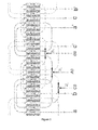
- the figure 1 generally illustrates a combined electric charging and supply device 100 formed by rechargeable batteries 110, an inverter 120 and an electric motor 130 according to the invention for both recharging the rechargeable batteries 110 from a network.
- three-phase electric 200 in charge mode and to feed the three-phase electric motor for its rotation in power mode.
- the inverter has an H-bridge structure for each phase of the motor thus making it possible to maintain the connection of the neutral of each phase of the motor during the charging of the batteries; however, the inverter may be, more conventionally, an inverter made with three-phase bridges and switching means of the power contactor type to switch from the charge mode of the batteries 110 to the power supply mode of the motor 130.
- the device 100 may furthermore comprise a DC / DC converter 140 (DC-DC) between the inverter 120 and the batteries 110 making it possible to adapt the voltage of the power supply network 200 to the characteristics of the batteries 110 and to optimize the power supply. sizing of the inverter 120 without degrading the efficiency of the device 100.
- DC-DC DC / DC converter 140
- the device 100 also comprises connection means 150 for connecting the device 100 to the electrical network 200 when the batteries need to be recharged.
- the electric motor 130 of AC type, formed by a rotor and a stator and the winding mode of the stator 130 AC motor.
- the rotor of the motor can be indifferently a permanent magnet rotor, an excitation winding rotor or a squirrel cage.
- stator of an AC electric motor 130 of a combined charging and supply device 100 comprises at least two coils which are connected to the phases of the electrical network when the device 100 is in charge mode.
- the stator comprises two phase windings and in the case of a three-phase load network, the stator comprises at least three phase windings.
- Three-phase motors are the most common motors in the industry and in motor vehicle traction systems as illustrated in figure 1 , we will describe mainly different winding modes of a three-phase motor.
- the invention is not limited to a three-phase motor and is applicable by analogy to a polyphase motor or a single-phase motor.
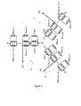
- the figure 2 is a diagram showing a first winding principle of a three-phase motor stator, whose three phases are denoted by A, B and C, integrating connection points A0, B0, C0 for the injection of the charging current and making it possible to get rid of the rotor movements in load mode.
- the stator is wound so that each phase of the stator connected to a phase of the network is formed by a plurality of 2n coils wired in series. Each of the coils of each phase involved in the formation of the different poles of the stator.
- connection points A0, B0, C0 are positioned so that they separate each phase winding A, B, C into two half-coils or two half-coils respectively comprising two connection points a-a ', b-b ', cc' advantageously connected to the branches of the inverter 120 as illustrated in FIG. figure 1 .
- connection points A0, B0, C0 are the midpoints of each phase coil and are positioned so that each of the two groups of coils have n coils in series and the same number of turns.
- the charging current injected at the mid-points A0, B0, C0 locally creates magnetomotive forces in the winding which oppose each other.
- each half-winding of a phase A, B, C comprises a plurality of coils wired together to reduce the magnetic coupling of each half-winding at the connection point A0, B0, C0 so that there is a non-zero apparent inductance at the middle point in charge mode.
- the apparent inductance is greater than the leakage inductance of the coils.
- the coils are wired as shown in figure 3 .
- the figure 3 illustrates the winding mode described previously in figure 2 on a three-phase stator with two pairs of distributed winding poles on two notches.
- each pole is formed by the association of a coil of each phase having two turns.
- the figure 3 also illustrates how to connect the mid-points A0, B0, C0 on each phase A, B, C according to the winding mode described in FIG. figure 2 .
- the three-phase load current 2i component A, 2i B 2 i C is injected on each phase of the stator connected with the three-phase network via the points A0 media, B0, C0 and distributed according to the illustrated arrows to the figure 3 .
- the figure 11 shows an example of distributed winding.
- a first winding is supplied by its terminals A10, A11.
- a second winding is supplied by its terminals A20, A21.
- the two windings have no common connection point.
- the figure 12 shows an example of distributed winding with a connection point O according to the prior art.
- a current delivered at connection point O is divided into a first current flowing in a first half-winding to exit at terminal a, and a second current flowing in a second half-winding to exit at terminal a '. It is observed that coils belonging to different half-windings are situated on the same side with respect to the point of connection O. These coils are strongly coupled but belong to different half-windings. Thus, the example of winding in figure 12 does not make it possible to obtain an apparent inductance greater than a leakage inductance of the coils.
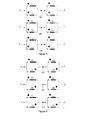
- the figure 4 is a diagram showing a second winding principle of a stator of a three-phase motor, whose three phases are denoted by A ', B' and C ', integrating midpoints A0', B0 ', C0' for the injection charging current and to overcome the rotor movements in charge mode.
- the stator winding consists in connecting n 'groups of coils in series, each n' groups of coils being formed by a plurality n of coils wired in parallel.
- the connection points of the ends of the phase windings a-a ', b-b', cc 'are advantageously connected to the branches of the inverter 120 as illustrated in FIG. figure 1 .
- each half-winding of a phase A, B, C comprises a plurality of coils wired together to reduce the magnetic coupling of each half-winding at the connection point A0, B0, C0 so that there is a non-zero apparent inductance at the middle point in charge mode.
- the apparent inductance is greater than the leakage inductance of the coils.
- the coils are wired as shown in figure 5 , 6 , 7 , 8 , or 9 .
- the series-parallel winding as illustrated allows to decouple magnetically the two half-windings on either side of the midpoint.
- the mutual inductance of the two half-coils is low which makes it possible to obtain an apparent inductance at the high mid-point required for the charging mode.
- the decoupling of the half-coils can also be increased or decreased by physically moving the two half-coils away from or towards the stator so that the reluctance of the stator iron intervenes in the decoupling of the two half-coils.
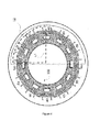
- the figure 5 illustrates for this purpose an example of wiring of an eight-pole series-parallel winding stator (ie four pairs of poles) of which each half-winding of a phase winding is diametrically separated.
- the visible points near the coils define the winding direction of the winding in the notches provided for this purpose on the stator.
- the figure 6 schematically represents a stator 300 wired according to the example of the figure 5 whose coils of the first half-winding are diametrically separated from the coils of the second half-winding.
- the reference L1 represents the mutual flow between two coils A1, A2 separated by a quarter turn in the indirect direction and the reference L2 represents the mutual flow between two coils A1, A3 diametrically opposed.
- the reluctance between the two diametrically opposite coils A1, A3 is greater than that between the two coils A1, A2 separated by a quarter turn in the indirect direction.
- the mutual flow L1 is therefore greater than the mutual flow L2.
- phase A the coils A1, A2 belong to the same half-coil, while the diametrically opposite coils A1, A3 belong to different half-coils.
- the decoupling of the two half-coils can be increased by the addition of air gaps on the stator 400 as illustrated in FIG. figure 7 .
- the figure 7 shows an example of an electric motor according to the invention comprising a stator wired according to the wiring example illustrated in FIG. figure 5 .
- the air gaps are defined by shims 170, preferably of a non-magnetic or non-metallic material. The length of the shims 170 determines the width of the gaps.
- phase A the air gaps increase the reluctance between the coils A1 and A3 with respect to the example in figure 6 .
- the coils A1 and A3 are even more weakly coupled than in the example of the figure 6 .
- the magnetic coupling of each half-winding at the connection point is therefore reduced compared to the example in FIG. figure 6 .
- the design of the rotor can also participate in addition to the decoupling of the two half-windings, in particular by the openings necessary for the location of the magnets, by the presence of air gap or by voluntary openings added in the rotor in order to increase the reluctance between the two half-windings of the stator.
- the figure 10 shows an example of an electric motor according to the invention in which the design of the rotor 600 participates in the decoupling of the two half-windings of a phase.
- the rotor 600 comprises openings 610 arranged in a radial direction.
- the openings 610 comprise magnets.
- the coils are wired as in the figure 5 .
- the openings 610 increase the reluctance between the coils A1 and A3 with respect to the example in FIG. figure 6 .
- the coils A1 and A3 are even more weakly coupled than in the example of the figure 6 .
- the magnetic coupling of each half-winding at the connection point is therefore reduced compared to the example in FIG. figure 6 .
- the figure 8 is a diagram showing a third winding principle of a stator of a three-phase motor, whose three phases are denoted A “, B” and C ", integrating midpoints A0", B0 ", C0" for the injection charging current and to overcome the rotor movements in charge mode.
- the coils In each half-winding, the coils have fluxes that compensate each other thanks to the winding in the opposite direction of the coils within the half-winding. Thus, the coupling of each half-coil at the point of connection of the phase is reduced, or even zero.
- phase A in a half-winding, the coils are wound in the opposite direction.
- the coils of a half-winding are traversed by the same current.
- the flow of the coil A1 compensates that of the coil A1 '
- the flux of the coil A2 compensates that of the coil A2'.
- the magnetic coupling of each half-winding at the connection point A0 is reduced or even zero.
- the illustrated winding makes it possible to obtain a stator whose phases are magnetically independent, which makes it possible to obtain a zero mutual inductance between the phases.
- This winding requires having a stator having twice as many teeth as a stator with a conventional winding but the stator diameter remains conserved because each tooth has two times less turns than a conventional winding.
- Such a winding is represented on a stator 500 with two pairs of poles, each half-winding of which is magnetically independent of the second with reference to FIG. figure 9 .
- the invention has mainly been described for a three-phase motor; however, the invention is also applicable by transposition to a polyphase electrical machine.
- the invention has mainly been described with a three-phase domestic electrical network; however, the invention is also applicable by transposition to a single-phase electrical network.
- the invention has been mainly described for an application in an electric motor vehicle; however, the invention can be used in other fields and in particular in power generating devices of the wind or hydraulic type.
Landscapes
- Engineering & Computer Science (AREA)
- Power Engineering (AREA)
- Transportation (AREA)
- Mechanical Engineering (AREA)
- Chemical & Material Sciences (AREA)
- Combustion & Propulsion (AREA)
- Electric Propulsion And Braking For Vehicles (AREA)
- Windings For Motors And Generators (AREA)
- Control Of Ac Motors In General (AREA)
- Secondary Cells (AREA)
- Charge And Discharge Circuits For Batteries Or The Like (AREA)
Abstract
Description
- La présente invention concerne un moteur électrique à courant alternatif d'un dispositif électrique combiné d'alimentation et de charge permettant d'alimenter un moteur électrique ou un alternateur par des batteries rechargeables.
- L'invention trouvera avantageusement une application dans le domaine des véhicules automobiles électriques ou hybrides dans lesquels les batteries peuvent alimenter le moteur via un onduleur et être rechargées lorsque l'automobile est à l'arrêt au moyen d'un réseau électrique alternatif.
- Toutefois bien que particulièrement prévu pour une telle application le dispositif électrique selon l'invention pourra être utilisé dans d'autres domaines et notamment dans des dispositifs de génération d'énergie de type éolien ou hydraulique.
- Classiquement, un véhicule électrique ou hybride comporte une chaîne de traction formée par des batteries rechargeables haute tension délivrant un courant continu à un onduleur qui transforme ce courant continu en un courant alternatif permettant d'alimenter un moteur électrique, de type machine électrique tournante, ce dernier assurant la mise en mouvement du véhicule.
- De manière à assurer la recharge de ces batteries haute tension il est connu d'équiper le véhicule d'un dispositif de charge embarqué comportant essentiellement un convertisseur alternatif-continu permettant de redresser la puissance alternative du réseau électrique domestique en puissance continue pour charger les batteries.
- Généralement, le dispositif de charge peut également comporter un pré-régulateur correcteur de facteur de puissance (Power Factor Corrector en langue anglaise) dont le rôle est de limiter la rejection d'harmonique sur le réseau électrique.
- Les composants électroniques de la chaîne d'alimentation d'une part et de la chaîne de charge d'autre part sont coûteux. Par ailleurs, l'alimentation du moteur et la charge des batteries s'effectuent à des phases différentes aussi il a été proposé, dans les demandes
EP 0 603 778 etWO97/08009 - A cet effet, le dispositif de charge des batteries utilise l'onduleur pour former un convertisseur alternatif continu ainsi que les bobinages du moteur pour former les inductances. Le passage du mode d'alimentation du moteur au mode de charge des batteries est assuré par des moyens de commutation avec des contacteurs de puissance en déconnectant le neutre.
- L'utilisation des connecteurs de puissance est toutefois problématique dans le sens où, assurant le passage des courants de la machine électrique, ils doivent être surdimensionnés. Pour pallier à cet inconvénient une solution consiste à réaliser une structure présentant des moyens de commutation intégrés avec des ponts en H.
- Toutefois, dans les deux cas précités l'utilisation des phases du moteur comme inductance pour redresser le courant du réseau électrique cause des perturbations au niveau du rotor du moteur. En effet, les inductances sont magnétisées par les courants alternatifs du réseau électrique créant ainsi des champs magnétiques. Ces champs magnétiques agissent sur le rotor qui peut entrer en mouvement, par exemple en vibrant, et même, en fonction des champs magnétiques et des caractéristiques du rotor, entrer en rotation. Cette mise en mouvement pose des problèmes à la fois de confort et de sécurité dans le cas d'une utilisation du dispositif électrique combiné dans un véhicule électrique même si ce dernier peut être équipé d'un système de découplage du train de la machine lors de la charge.
- Pour pallier à cet inconvénient une solution consiste à réaliser une compensation statique consistant à injecter le courant de charge dans au moins un bobinage du stator relié à une phase du réseau en utilisant un point de connexion supplémentaire, dit point milieu.
- Un bobinage du stator comporte de façon classique une pluralité de bobines formées par une pluralité de spires.
- Le point milieu, sépare le bobinage de phase du stator en deux parties de sorte que le courant de charge, injecté via le point de milieu, est divisé en deux courants circulants dans des sens opposés à travers chaque demi-bobinage, chaque demi-bobinage comportant le même nombre de spires.
- Cette solution de compensation par injection du courant de charge dans les points milieux des bobinages de phases a pour conséquence d'annuler la force magnétomotrice et d'annuler les inductances des deux demi-bobinages. Seule reste apparente l'inductance de fuite très faible liée aux imperfections des bobines.
- Une inductance trop faible du moteur a pour conséquence de rendre le contrôle des courants de charge difficiles, notamment à cause des importantes ondulations du courant à la fréquence de découpage.
- Dans ce contexte, la présente invention vise à proposer un moteur électrique à courant alternatif pour un dispositif permettant d'alimenter le moteur électrique, et de recharger des batteries en utilisant des éléments de la chaîne d'alimentation, c'est-à-dire des éléments du moteur et de l'onduleur, et tel que le moteur électrique comporte un bobinage du stator permettant d'obtenir une inductance apparente au point milieu suffisamment importante pour pallier aux inconvénients précités tout en s'affranchissant de la mise en mouvement du rotor en mode charge.
- A cette fin, l'invention propose un moteur électrique à courant alternatif d'un dispositif électrique combiné d'alimentation et de charge, ledit moteur électrique étant formé par un stator relié à un réseau électrique dont le nombre de phase est inférieur au nombre de phase dudit moteur, ledit courant de charge dudit réseau étant injecté via un point de connexion divisant chaque phase dudit stator reliée à une phase dudit réseau en deux demi-bobinage, ledit moteur étant caractérisé en ce que chaque demi-bobinage de phase du stator comporte une pluralité de bobines câblées de façon à réduire le couplage magnétique de chaque demi-bobinage au niveau dudit point de connexion de sorte qu'il réside une inductance apparente non nulle au point de connexion en mode charge dudit dispositif.
- Par exemple, les bobines d'une phase sont réparties de part et d'autre du point de connexion de la phase de façon à réduire le couplage magnétique des demi-bobinages au niveau du point de connexion.
- Dans un exemple particulier, les bobines couplées, voire fortement couplées, entre elles sont mises d'un même côté par rapport au point de connexion. Autrement dit, les bobines couplées, voire fortement couplées, entre elles appartiennent au même demi-bobinage. En outre, les bobines non couplées, voire faiblement couplées, entre elles sont mises dans des côtés différents par rapport au point de connexion. Autrement dit, les bobines non couplées, voire faiblement couplées, entre elles appartiennent à des demi-bobinages différents.
- Par exemple, chaque bobine est répartie sur plusieurs encoches. Deux bobines d'une phase appartenant à des demi-bobinages différents sont réparties sur des encoches situées respectivement de part et d'autre du point de connexion.
- Par exemple, chaque demi-bobinage comprend au moins deux bobines enroulées en sens inverse l'une par rapport à l'autre de façon à réduire le couplage magnétique entre les deux demi-bobinages d'une phase. Dans un exemple particulier chaque demi-bobinage comprend un nombre pair de bobines, chaque bobine ayant une bobine correspondante enroulée en sens inverse.
- Ainsi, le mode de bobinage selon l'invention permet d'obtenir une valeur élevée de l'inductance apparente en mode charge au niveau du point de connexion tout en s'affranchissant de la mise en mouvement du rotor en mode charge.
- Le découplage des demi-bobinages de chaque phase du stator permet ainsi d'améliorer la charge des batteries du dispositif ainsi que le contrôle du courant de charge.
- En effet, l'inductance apparente lors de la charge est augmentée et est supérieure à une inductance de fuite des bobines. En particulier, l'inductance apparente correspond à une inductance utile du moteur. Par exemple, l'inductance apparente au point de connexion en mode charge est comprise entre 1 mH et 100 mH.
- Outre les caractéristiques principales qui viennent d'être mentionnées dans le paragraphe précédent, le moteur électrique à courant alternatif selon l'invention, peut présenter une ou plusieurs caractéristiques supplémentaires ci-dessous, considérées individuellement ou selon toutes les combinaisons techniquement possibles :
- chaque demi-bobinage est formé par une pluralité n de bobines câblées en série ;
- chaque demi-bobinage est formé par une pluralité n'/2 groupes de bobines câblées en série, chacun desdits groupes comportant une pluralité n de bobines câblées en parallèle ;
- chaque demi-bobinage comporte le même nombre de spires ;
- chacun des demi-bobinages d'une phase est diamétralement opposé sur ledit stator de façon à réduire le couplage magnétiques entre deux demi-bobinages d'une phase ;
- ledit stator comporte des entrefers à sa périphérie permettant de réduire le couplage magnétique entre les deux demi-bobinages d'une phase ;
- ledit moteur comporte un rotor comportant des ouvertures et/ou des entrefers permettant d'augmenter la réluctance entre les deux demi-bobinages de chaque phase dudit stator.
- L'invention a également pour objet un dispositif électrique combiné d'alimentation et de charge comportant un moteur électrique à courant alternatif selon l'invention relié à un réseau électrique, un onduleur et des moyens d'accumulation d'énergie électrique.
- Avantageusement, le dispositif électrique comporte également un convertisseur continu-continu.
- La présente invention sera mieux comprise à la lecture d'un exemple détaillé de réalisation en référence aux dessins annexés, fournis à titre d'exemple non limitatif, parmi lesquels :
- la
figure 1 représente de manière schématique un dispositif électrique combiné de charge et d'alimentation comportant un moteur électrique selon l'invention implanté dans un véhicule automobile ; - la
figure 2 représente de manière schématique un premier mode de bobinage d'un stator de moteur triphasé d'un moteur électrique selon l'invention ; - la
figure 3 représente de manière schématique un exemple de réalisation du mode de bobinage illustré à lafigure 2 sur un stator triphasé à deux paires de pôles à bobinage réparti sur deux encoches ; - la
figure 4 représente de manière schématique un deuxième mode de bobinage d'un stator de moteur triphasé d'un moteur électrique selon l'invention ; - la
figure 5 représente de manière schématique un exemple de câblage d'un stator à bobinage série-parallèle à quatre pôles selon le deuxième mode de bobinage illustré à lafigure 4 ; - la
figure 6 représente de manière schématique un stator câblé selon l'exemple de câblage illustré à lafigure 5 ; - la
figure 7 représente de manière schématique un deuxième mode de réalisation d'un stator câblé selon l'exemple de câblage illustré à lafigure 5 ; - la
figure 8 représente de manière schématique un troisième mode de bobinage d'un stator de moteur triphasé d'un moteur électrique selon l'invention ; - la
figure 9 représente de manière schématique un stator à deux paires de pôles câblés selon le troisième mode de câblage illustré à lafigure 8 dont chaque demi-bobinage est indépendant magnétiquement du second ; - la
figure 10 représente de manière schématique un moteur électrique selon l'invention comprenant un rotor ayant des ouvertures et un stator câblé selon l'exemple de câblage illustré à lafigure 5 ; - la
figure 11 représente de manière schématique un exemple de bobinage réparti sans point de connexion ; - la
figure 12 représente de manière schématique un exemple de bobinage réparti avec point de connexion selon l'art antérieur. - La
figure 1 illustre de façon générale un dispositif électrique combiné de charge et d'alimentation 100 formé par des batteries rechargeables 110, un onduleur 120 et un moteur électrique 130 selon l'invention permettant à la fois de recharger les batteries rechargeables 110 à partir d'un réseau électrique 200 triphasé en mode charge et d'alimenter le moteur électrique triphasé pour sa mise en rotation en mode alimentation. - Avantageusement, l'onduleur a une structure de pont en H pour chaque phase du moteur permettant ainsi de conserver la connexion du neutre de chaque phase du moteur lors de la charge des batteries ; toutefois l'onduleur peut être, de façon plus classique, un onduleur réalisé avec des ponts triphasés et des moyens de commutation de type contacteur de puissance pour passer du mode charge des batteries 110 au mode d'alimentation du moteur 130.
- Le dispositif 100 peut comporter en outre un convertisseur DC/DC 140 (continu-continu) entre l'onduleur 120 et les batteries 110 permettant d'adapter la tension du réseau électrique d'alimentation 200 aux caractéristiques des batteries 110 et d'optimiser le dimensionnement de l'onduleur 120 sans dégrader le rendement du dispositif 100.
- Enfin, le dispositif 100 comporte également des moyens de liaisons 150 pour relier le dispositif 100 au réseau électrique 200 lorsque les batteries ont besoin d'être rechargé.
- Dans la suite de la demande, on s'intéressera plus particulièrement au moteur électrique 130, de type à courant alternatif, formé par un rotor et un stator ainsi qu'au mode de bobinage du stator du moteur 130 à courant alternatif. Le rotor du moteur peut être indifféremment un rotor à aimant permanent, un rotor à bobinage d'excitation ou encore une cage d'écureuil.
- De façon générale, le stator d'un moteur électrique 130 à courant alternatif d'un dispositif combiné de charge et d'alimentation 100 comporte au moins deux bobinages qui sont reliés aux phases du réseau électrique lorsque le dispositif 100 est en mode charge.
- Dans le cas d'un réseau de charge monophasé, le stator comporte deux bobinages de phases et dans le cas d'un réseau de charge triphasé, le stator comporte au moins trois bobinages de phases.
- Les moteurs triphasés étant les moteurs les plus répandus dans l'industrie et dans les systèmes de traction de véhicule automobile comme illustré à la
figure 1 , nous décrirons principalement différents modes de bobinage d'un moteur triphasé. Toutefois, l'invention n'est pas limitée à un moteur triphasé et elle est applicable par analogie à un moteur polyphasé ou à un moteur monophasé. - La
figure 2 est un schéma représentant un premier principe de bobinage d'un stator de moteur triphasé, dont les trois phases sont notées A, B et C, intégrant des points de connexion A0, B0, C0 pour l'injection du courant de charge et permettant de s'affranchir des mouvements du rotor en mode charge. - Dans ce premier mode de réalisation, le stator est bobiné de sorte que chaque phase du stator reliée à une phase du réseau est formée par une pluralité 2n de bobines câblées en série. Chacune des bobines de chaque phase participant à la formation des différents pôles du stator.
- Les points de connexion A0, B0, C0 sont positionnés de sorte qu'ils séparent chaque bobinage de phase A, B, C en deux demi-bobinage ou deux demi-bobines comportant respectivement deux points de connexion a-a', b-b', c-c' reliés avantageusement aux branches de l'onduleur 120 tel qu'illustré à la
figure 1 . - Avantageusement, les points de connexion A0, B0, C0 sont les points milieux de chaque bobinage de phase et sont positionnés de sorte que chacun des deux groupes de bobines comportent n bobines en série et le même nombre de spires.
- Avec ce premier mode de bobinage, le courant de charge injecté aux points milieux A0, B0, C0 crée localement des forces magnétomotrices dans le bobinage qui s'opposent.
- En outre, chaque demi-bobinage d'une phase A, B, C comporte une pluralité de bobines câblées entre elles de façon à réduire le couplage magnétique de chaque demi-bobinage au niveau du point de connexion A0, B0, C0 de sorte qu'il réside une inductance apparente non nulle au point milieu en mode charge. En particulier, l'inductance apparente est supérieure à l'inductance de fuite des bobines. Par exemple, les bobines sont câblées comme illustré en
figure 3 . - Les inductances propres de chaque demi-bobinage ne s'annulent pas ce qui permet de bénéficier aux points milieux A0, B0, C0 d'une inductance apparente non nulle en mode charge et donc très largement supérieure à l'inductance de fuite liée aux imperfections des bobines.
- La
figure 3 illustre le mode de bobinage décrit précédemment à lafigure 2 sur un stator triphasé à deux paires de pôles à bobinage réparti sur deux encoches. Dans cet exemple, chaque pôle est formé par l'association d'une bobine de chaque phase comportant deux spires. Lafigure 3 illustre également comment connecter les points milieux A0, B0, C0 sur chaque phase A, B, C selon le mode de bobinage décrit à lafigure 2 . Ainsi, en mode charge, le courant de charge triphasé de composante 2iA, 2iB, 2i C est injecté sur chaque phase du stator reliée avec le réseau triphasé via les points milieux A0, B0, C0 et se réparti selon les flèches illustrées à lafigure 3 . - L'exemple en
figure 3 selon l'invention sera mieux compris en faisant référence auxfigures 11 et 12 . - La
figure 11 présente un exemple de bobinage réparti. Un premier enroulement est alimenté par ses bornes A10, A11. Un second enroulement est alimenté par ses bornes A20, A21. Les deux enroulements n'ont pas de point de connexion commun. - La
figure 12 présente un exemple de bobinage réparti avec un point de connexion O selon l'art antérieur. Un courant délivré au point de connexion O se divise en un premier courant circulant dans un premier demi-bobinage pour sortir à la borne a, et en un second courant circulant dans un second demi-bobinage pour sortir à la borne a'. On observe que des bobines appartenant à des demi-bobinages différents sont situées du même côté par rapport au point de connexion O. Ces bobines sont fortement couplées mais appartiennent à des demi-bobinages différents. Ainsi, l'exemple de bobinage enfigure 12 ne permet pas d'obtenir une inductance apparente supérieure à une inductance de fuite des bobines. - La
figure 4 est un schéma représentant un deuxième principe de bobinage d'un stator d'un moteur triphasé, dont les trois phases sont notées A', B' et C', intégrant des points milieux A0', B0', C0' pour l'injection du courant de charge et permettant de s'affranchir des mouvements du rotor en mode charge. - Dans ce deuxième mode de réalisation, le bobinage du stator consiste à relier n' groupes de bobines en série, chacun des n' groupes de bobines étant formé par une pluralité n de bobines câblées en parallèle.
- L'avantage d'un tel bobinage, dit bobinage série-parallèle tel qu'illustré, permet dans un premier temps de réaliser un bobinage avec des conducteurs de faible section car le courant de charge se répartit de manière équilibrée dans les différentes branches en parallèle du bobinage, ce qui facilite les opérations de bobinage.
- Les points de connexion A0', B0', C0' sont positionnés de sorte qu'ils séparent le bobinage en deux demi-bobinages comportant plusieurs groupes de n bobines en parallèle. Selon un mode avantageux, les points de connexion A0', B0', C0' sont les points milieux des bobinages de phase du stator. Dans ce cas, les points de connexion A0', B0', C0' sont positionnés de sorte que les bobinages de phase sont partitionnées en deux demi-bobinages symétriques ayant de part et d'autre autant de bobines et formant de part et d'autre autant de paires de pôles, c'est-à-dire (n'.n)/2 pôles. De façon similaire au mode de bobinage précédent, les points de connexion des extrémités des bobinages de phase a-a', b-b', c-c' sont reliés avantageusement aux branches de l'onduleur 120 tel qu'illustré à la
figure 1 . - En outre, chaque demi-bobinage d'une phase A, B, C comporte une pluralité de bobines câblées entre elles de façon à réduire le couplage magnétique de chaque demi-bobinage au niveau du point de connexion A0, B0, C0 de sorte qu'il réside une inductance apparente non nulle au point milieu en mode charge. En particulier, l'inductance apparente est supérieure à l'inductance de fuite des bobines. Par exemple, les bobines sont câblées comme illustré en
figure 5 ,6 ,7 ,8 , ou9 . - Le bobinage série-parallèle tel qu'illustré permet ainsi de découpler magnétiquement les deux demi-bobinages de part et d'autre du point milieu. Ainsi, l'inductance mutuelle des deux demi-bobinages est faible ce qui permet d'obtenir une inductance apparente au point milieu élevée nécessaire au mode charge.
- Le découplage des demi-bobinages peut également être augmenté ou diminué en éloignant ou en rapprochant physiquement les deux demi-bobinages sur le stator de sorte que la réluctance du fer du stator intervient dans le découplage des deux demi-bobinages.
- La
figure 5 illustre à cet effet un exemple de câblage d'un stator à bobinage série-parallèle à huit pôles (i.e. quatre paires de pôles) dont chaque demi-bobinage d'un bobinage de phase est séparé diamétralement. - Sur la
figure 5 , les points visibles à proximité des bobines définissent le sens d'enroulement du bobinage dans les encoches prévues à cet effet sur le stator. - La
figure 6 représente schématiquement un stator 300 câblé selon l'exemple de lafigure 5 dont les bobines du premier demi-bobinage sont séparées diamétralement des bobines du second demi-bobinage. - La référence L1 représente le flux mutuel entre deux bobines A1, A2 séparées d'un quart de tour dans le sens indirect et la référence L2 représente le flux mutuel entre deux bobines A1, A3 diamétralement opposées.
- La reluctance entre les deux bobines A1, A3 diamétralement opposées est supérieure à celle entre les deux bobines A1, A2 séparées d'un quart de tour dans le sens indirect. Le flux mutuel L1 est donc supérieur au flux mutuel L2. Ainsi, les deux bobines A1, A2 séparées d'un quart de tour dans le sens indirect sont fortement couplées, alors que les deux bobines A1, A3 diamétralement opposées sont faiblement couplées.
- Ainsi, dans la phase A, les bobines A1, A2 appartiennent au même demi-bobinage, tandis que les bobines A1, A3 diamétralement opposées appartiennent à des demi-bobinages différents.
- Une répartition similaire des bobines s'applique aux autres phases B, C.
- Selon un autre mode de réalisation, le découplage des deux demi-bobinages peut être augmenté par l'ajout d'entrefers sur le stator 400 tel qu'illustré à la
figure 7 . - La
figure 7 présente un exemple de moteur électrique selon l'invention comprenant un stator câblé selon l'exemple de câblage illustré à lafigure 5 . Les entrefers sont définis grâce à des cales 170, de préférence en un matériau non magnétique ou non métallique. La longueur des cales 170 détermine la largeur des entrefers. - En considérant la phase A, les entrefers augmentent la reluctance entre les bobines A1 et A3 par rapport à l'exemple en
figure 6 . Ainsi, les bobines A1 et A3 sont encore plus faiblement couplées que dans l'exemple de lafigure 6 . Le couplage magnétique de chaque demi-bobinage au niveau du point de connexion est donc diminué par rapport à l'exemple enfigure 6 . - Enfin, la conception du rotor peut également participer en complément au découplage des deux demi-bobinages, notamment par les ouvertures nécessaires à l'emplacement des aimants, par la présence d'entrefer ou encore par des ouvertures volontaires rajoutées dans le rotor afin d'augmenter la réluctance entre les deux demi-bobinages du stator.
- La
figure 10 présente un exemple de moteur électrique selon l'invention dans lequel la conception du rotor 600 participe au découplage des deux demi-bobinages d'une phase. Le rotor 600 comprend des ouvertures 610 disposées selon une direction radiale. Dans un exemple particulier, les ouvertures 610 comprennent des aimants. - Dans l'exemple de la
figure 10 , les bobines sont câblées comme dans lafigure 5 . En considérant la phase A, les ouvertures 610 augmentent la reluctance entre les bobines A1 et A3 par rapport à l'exemple enfigure 6 . Ainsi, les bobines A1 et A3 sont encore plus faiblement couplées que dans l'exemple de lafigure 6 . Le couplage magnétique de chaque demi-bobinage au niveau du point de connexion est donc diminué par rapport à l'exemple enfigure 6 . - La
figure 8 est un schéma représentant un troisième principe de bobinage d'un stator d'un moteur triphasé, dont les trois phases sont notées A", B" et C", intégrant des points milieux A0", B0", C0" pour l'injection du courant de charge et permettant de s'affranchir des mouvements du rotor en mode charge. - Dans chaque demi-bobinage, les bobines ont des flux qui se compensent entre eux grâce à l'enroulement en sens inverse des bobines au sein du demi-bobinage. Ainsi, le couplage de chaque demi-bobinage au niveau du point de connexion de la phase est réduit, voire nul.
- En considérant la phase A, dans un demi-bobinage, les bobines sont enroulées en sens inverse. Les bobines d'un demi-bobinage sont parcourues par un même courant. Ainsi, le flux de la bobine A1 compense celui de la bobine A1', et le flux de la bobine A2 compense celui de la bobine A2'. Le couplage magnétique de chaque demi-bobinage au niveau du point de connexion A0 est donc réduit, voire nul.
- Le bobinage illustré permet d'obtenir un stator dont les phases sont magnétiquement indépendantes, ce qui permet d'obtenir une inductance mutuelle nulle entre les phases.
- Ce bobinage nécessite de disposer d'un stator comportant deux fois plus de dents qu'un stator avec un bobinage classique mais le diamètre du stator reste conservé car chaque dent comporte deux fois moins de spires qu'un bobinage classique.
- Un tel bobinage est représenté sur un stator 500 à deux paires de pôles dont chaque demi-bobinage est indépendant magnétiquement du second en référence à la
figure 9 . - L'invention a été principalement décrite pour un moteur triphasé ; toutefois, l'invention est également applicable par transposition à une machine électrique polyphasée.
- L'invention a été principalement décrite avec un réseau électrique domestique de type triphasé ; toutefois, l'invention est également applicable par transposition à un réseau électrique monophasé.
- L'invention a été principalement décrite pour une application dans un véhicule automobile électrique ; toutefois, l'invention pourra être utilisée dans d'autres domaines et notamment dans des dispositifs de génération d'énergie de type éolien ou hydraulique.
- Les autres avantages de l'invention sont notamment les suivants :
- amélioration du filtrage des courants en mode charge ;
- amélioration du contrôle des composantes homopolaires en mode d'alimentation ;
- amélioration des tolérances du moteur en cas d'une panne d'une phase du moteur.
Claims (13)
- Moteur électrique (130) à courant alternatif d'un dispositif électrique combiné d'alimentation et de charge (100), ledit moteur électrique (130) étant formé par un stator (300, 400, 500) relié à un réseau électrique (200) dont le nombre de phase est inférieur au nombre de phase dudit moteur (130), ledit courant de charge dudit réseau (200) étant injecté via un point de connexion divisant chaque phase dudit stator reliée à une phase dudit réseau en deux demi-bobinage, ledit moteur (130) étant caractérisé en ce que chaque demi-bobinage d'une phase comporte une pluralité de bobines câblées entre elles de façon à réduire le couplage magnétique de chaque demi-bobinage au niveau dudit point de connexion de sorte qu'il réside une inductance apparente non nulle au dit point de connexion en mode charge dudit dispositif (100).
- Moteur électrique (130) à courant alternatif selon la revendication 1 caractérisé en ce que chaque demi-bobinage est formé par une pluralité n de bobines câblées en série.
- Moteur électrique (130) à courant alternatif selon la revendication 1 caractérisé en ce que chaque demi-bobinage est formé par une pluralité n'/2 groupes de bobines câblées en série, chacun desdits groupes comportant une pluralité n de bobines câblées en parallèle.
- Moteur électrique (130) à courant alternatif selon l'une des revendications 1 à 3 caractérisé en ce que chaque demi-bobinage comporte le même nombre de spires.
- Moteur électrique (130) à courant alternatif selon l'une des revendications 1 à 4 caractérisé en ce que chacun des demi-bobinages d'une phase est diamétralement opposé sur ledit stator de façon à réduire le couplage magnétiques entre deux demi-bobinages d'une phase.
- Moteur électrique (130) à courant alternatif selon l'une des revendications 1 à 5 caractérisé en ce que ledit stator (400) comporte des entrefers à sa périphérie permettant de réduire le couplage magnétique entre les deux demi-bobinages d'une phase.
- Moteur électrique (130) à courant alternatif selon l'une des revendications 1 à 6 caractérisé en ce que ledit moteur comporte un rotor (600) comportant des ouvertures (610) et/ou des entrefers permettant d'augmenter la réluctance entre les deux demi-bobinages de chaque phase dudit stator.
- Moteur électrique (130) à courant alternatif selon l'une des revendications 1 à 7 caractérisé en ce que les bobines d'une phase sont réparties de part et d'autre du point de connexion de la phase de façon à réduire le couplage magnétique des demi-bobinages au niveau du point de connexion.
- Moteur électrique (130) à courant alternatif selon l'une des revendications 1 à 8 caractérisé en ce que chaque bobine est répartie sur plusieurs encoches, et en ce que deux bobines d'une phase appartenant à des demi-bobinages différents sont réparties sur des encoches situées respectivement de part et d'autre du point de connexion.
- Moteur électrique (130) à courant alternatif selon l'une des revendications 1 à 9 caractérisé en ce que chaque demi-bobinage comprend au moins deux bobines enroulées en sens inverse l'une par rapport à l'autre de façon à réduire le couplage magnétique entre les deux demi-bobinages d'une phase.
- Moteur électrique (130) à courant alternatif selon la revendication 10 caractérisé en ce chaque demi-bobinage comprend un nombre pair de bobines, chaque bobine ayant une bobine correspondante enroulée en sens inverse.
- Dispositif électrique combiné d'alimentation et de charge (100) comportant :- un moteur électrique (130) à courant alternatif selon l'une des revendications 1 à 11 relié à un réseau électrique (200) ;- un onduleur (120) ;- des moyens d'accumulation d'énergie électrique (110).
- Dispositif électrique combiné d'alimentation et de charge (100) selon la revendication 12 caractérisé en ce qu'il comporte un convertisseur continu-continu (140).
Applications Claiming Priority (1)
| Application Number | Priority Date | Filing Date | Title |
|---|---|---|---|
| FR1055084A FR2961970B1 (fr) | 2010-06-25 | 2010-06-25 | Moteur electrique a courant alternatif d'un dispositif electrique combine d'alimentation et de charge |
Publications (2)
| Publication Number | Publication Date |
|---|---|
| EP2400636A1 true EP2400636A1 (fr) | 2011-12-28 |
| EP2400636B1 EP2400636B1 (fr) | 2020-04-22 |
Family
ID=43795042
Family Applications (1)
| Application Number | Title | Priority Date | Filing Date |
|---|---|---|---|
| EP11305804.4A Active EP2400636B1 (fr) | 2010-06-25 | 2011-06-24 | Moteur électrique à courant alternatif pouvant être branché dans le circuit de charge de batteries |
Country Status (8)
| Country | Link |
|---|---|
| US (1) | US8629636B2 (fr) |
| EP (1) | EP2400636B1 (fr) |
| JP (1) | JP5940770B2 (fr) |
| KR (1) | KR101900099B1 (fr) |
| CN (1) | CN102332766B (fr) |
| BR (1) | BRPI1102954A2 (fr) |
| CA (1) | CA2744779A1 (fr) |
| FR (1) | FR2961970B1 (fr) |
Cited By (2)
| Publication number | Priority date | Publication date | Assignee | Title |
|---|---|---|---|---|
| CN113815462A (zh) * | 2021-09-24 | 2021-12-21 | 上汽通用五菱汽车股份有限公司 | 新能源汽车充电管理方法、装置及计算机可读存储介质 |
| US11511637B2 (en) | 2019-05-24 | 2022-11-29 | Huawei Digital Power Technologies Co., Ltd. | Integrated charger and motor control system |
Families Citing this family (11)
| Publication number | Priority date | Publication date | Assignee | Title |
|---|---|---|---|---|
| FR2944391B1 (fr) * | 2008-11-18 | 2013-03-22 | Valeo Sys Controle Moteur Sas | Procede et dispositif electrique combine d'alimentation et de charge a moyens de compensation |
| DE102012202764A1 (de) * | 2012-02-23 | 2013-08-29 | Siemens Aktiengesellschaft | Ladevorrichtung eines elektrisch betriebenen Fahrzeugs |
| JP6139256B2 (ja) * | 2013-05-10 | 2017-05-31 | 株式会社東芝 | 回転電機の電機子巻線 |
| DE102014204956A1 (de) * | 2014-03-18 | 2015-09-24 | Robert Bosch Gmbh | Verfahren zur Erkennung von Anomalien in einer Batteriezelle und Kurzschlusssensorik |
| US9193273B1 (en) * | 2014-06-15 | 2015-11-24 | Efficient Drivetrains, Inc. | Vehicle with AC-to-DC inverter system for vehicle-to-grid power integration |
| FR3028683B1 (fr) | 2014-11-17 | 2017-12-29 | Lohr Electromecanique | Procede de recharge de moyens d'accumulation d'energie equipant un vehicule electrique ou hybride |
| DE102016218304B3 (de) * | 2016-09-23 | 2018-02-01 | Volkswagen Aktiengesellschaft | Vorrichtung zur Spannungswandlung, Traktionsnetz und Verfahren zum Laden einer Batterie |
| DE102018203134A1 (de) * | 2018-03-02 | 2019-09-05 | Zf Friedrichshafen Ag | Antriebsvorrichtung mit Transformationsfunktion, Antriebssystem und Verfahren zum Betreiben einer Antriebsvorrichtung |
| JP2019164638A (ja) * | 2018-03-20 | 2019-09-26 | 本田技研工業株式会社 | 情報提供装置、情報提供システム、及び情報提供方法 |
| KR102194406B1 (ko) | 2018-11-29 | 2020-12-24 | 경북대학교 산학협력단 | 충전 어셈블리 |
| CN115962708B (zh) * | 2023-01-12 | 2026-04-21 | 中国人民解放军海军工程大学 | 基于柔性电路线圈的磁轴承定转子气隙测量方法 |
Citations (5)
| Publication number | Priority date | Publication date | Assignee | Title |
|---|---|---|---|---|
| FR1270277A (fr) * | 1960-10-11 | 1961-08-25 | Nat Res Dev | Moteur à vitesse continuement variable par modulation d'amplitude de pôles |
| EP0603778A1 (fr) | 1992-12-25 | 1994-06-29 | Fuji Electric Co., Ltd. | Système électrique d'un véhicule électrique |
| WO1997008009A1 (fr) | 1995-08-30 | 1997-03-06 | Renault | Systeme d'alimentation electrique mixte onduleur et convertisseur alternatif-continu |
| FR2844646A1 (fr) * | 2002-09-17 | 2004-03-19 | Denso Corp | Machine rotative electrique a haute tension |
| WO2010057893A1 (fr) * | 2008-11-18 | 2010-05-27 | Valeo Systemes De Controle Moteur | Procede et dispositif electrique combine d'alimentation et de charge a moyens de compensation |
Family Cites Families (10)
| Publication number | Priority date | Publication date | Assignee | Title |
|---|---|---|---|---|
| US4990809A (en) * | 1987-04-27 | 1991-02-05 | The Superior Electric Company | Variable reluctance motor |
| US5264736A (en) * | 1992-04-28 | 1993-11-23 | Raytheon Company | High frequency resonant gate drive for a power MOSFET |
| JP2002199639A (ja) * | 1996-02-23 | 2002-07-12 | Matsushita Electric Ind Co Ltd | 電動機 |
| BR9804426A (pt) * | 1998-10-16 | 2000-05-16 | Elevadores Atlas S A | Máquina elétrica de relutância subsìncrona. |
| JP2003333811A (ja) * | 2002-05-12 | 2003-11-21 | Yoshimitsu Okawa | 軸方向に分割された複数の固定子巻線を有する誘導電動機 |
| JP3864878B2 (ja) * | 2002-09-17 | 2007-01-10 | 株式会社デンソー | 高電圧回転電機 |
| CN100454725C (zh) * | 2004-08-06 | 2009-01-21 | 中国人民解放军海军工程大学 | 多相整流/三相辅助励磁控制的高速感应发电机 |
| CN2775919Y (zh) * | 2005-04-07 | 2006-04-26 | 董常发 | 直流电焊、发电、充电多用机 |
| JP2008109796A (ja) * | 2006-10-26 | 2008-05-08 | Toyota Motor Corp | 回転電機の巻線構造 |
| CN101741161A (zh) * | 2009-12-31 | 2010-06-16 | 华北电力大学 | 一种稀土永磁电动机及其控制方法 |
-
2010
- 2010-06-25 FR FR1055084A patent/FR2961970B1/fr not_active Expired - Fee Related
-
2011
- 2011-06-23 CA CA2744779A patent/CA2744779A1/fr not_active Abandoned
- 2011-06-24 BR BRPI1102954-4A patent/BRPI1102954A2/pt not_active Application Discontinuation
- 2011-06-24 EP EP11305804.4A patent/EP2400636B1/fr active Active
- 2011-06-24 US US13/168,061 patent/US8629636B2/en not_active Expired - Fee Related
- 2011-06-27 JP JP2011141323A patent/JP5940770B2/ja not_active Expired - Fee Related
- 2011-06-27 CN CN201110268074.XA patent/CN102332766B/zh active Active
- 2011-06-27 KR KR1020110062303A patent/KR101900099B1/ko active Active
Patent Citations (5)
| Publication number | Priority date | Publication date | Assignee | Title |
|---|---|---|---|---|
| FR1270277A (fr) * | 1960-10-11 | 1961-08-25 | Nat Res Dev | Moteur à vitesse continuement variable par modulation d'amplitude de pôles |
| EP0603778A1 (fr) | 1992-12-25 | 1994-06-29 | Fuji Electric Co., Ltd. | Système électrique d'un véhicule électrique |
| WO1997008009A1 (fr) | 1995-08-30 | 1997-03-06 | Renault | Systeme d'alimentation electrique mixte onduleur et convertisseur alternatif-continu |
| FR2844646A1 (fr) * | 2002-09-17 | 2004-03-19 | Denso Corp | Machine rotative electrique a haute tension |
| WO2010057893A1 (fr) * | 2008-11-18 | 2010-05-27 | Valeo Systemes De Controle Moteur | Procede et dispositif electrique combine d'alimentation et de charge a moyens de compensation |
Cited By (2)
| Publication number | Priority date | Publication date | Assignee | Title |
|---|---|---|---|---|
| US11511637B2 (en) | 2019-05-24 | 2022-11-29 | Huawei Digital Power Technologies Co., Ltd. | Integrated charger and motor control system |
| CN113815462A (zh) * | 2021-09-24 | 2021-12-21 | 上汽通用五菱汽车股份有限公司 | 新能源汽车充电管理方法、装置及计算机可读存储介质 |
Also Published As
| Publication number | Publication date |
|---|---|
| KR101900099B1 (ko) | 2018-09-18 |
| US8629636B2 (en) | 2014-01-14 |
| CN102332766B (zh) | 2016-01-13 |
| EP2400636B1 (fr) | 2020-04-22 |
| KR20120000543A (ko) | 2012-01-02 |
| US20110316454A1 (en) | 2011-12-29 |
| JP5940770B2 (ja) | 2016-06-29 |
| JP2012070613A (ja) | 2012-04-05 |
| CN102332766A (zh) | 2012-01-25 |
| FR2961970A1 (fr) | 2011-12-30 |
| BRPI1102954A2 (pt) | 2015-07-28 |
| FR2961970B1 (fr) | 2017-03-10 |
| CA2744779A1 (fr) | 2011-12-25 |
Similar Documents
| Publication | Publication Date | Title |
|---|---|---|
| EP2400636B1 (fr) | Moteur électrique à courant alternatif pouvant être branché dans le circuit de charge de batteries | |
| EP2367705B1 (fr) | Procede et dispositif electrique combine d'alimentation et de charge a moyens de compensation | |
| EP2367704B1 (fr) | Dispositif electrique combine d'alimentation et de charge | |
| EP1609226B1 (fr) | Machine electrique synchrone comportant un stator et au moins un retor et dispositif de commande associe | |
| WO2020016510A1 (fr) | Aeronef multi-rotors comprenant un systeme de propulsion et de generation electrique non propulsive | |
| EP3365970B1 (fr) | Démarreur-générateur de turbomachine a machine électrique asynchrone multi-enroulements | |
| FR2947115A1 (fr) | Machine dynamoelectrique | |
| EP2413471A2 (fr) | Dispositif de charge de moyens d'accumulation | |
| JP2012070613A5 (fr) | ||
| FR3084796A1 (fr) | Convertisseur de tension continu-continu a resonance | |
| EP4566151A1 (fr) | Machine electrique de traction a flux axial | |
| EP3183795B1 (fr) | Chargeur de batterie pour un véhicule automobile électrique ou hybride à haute intégration | |
| EP3175530B1 (fr) | Chargeur et procédé de charge de batterie de véhicule automobile électrique ou hybride a machine a reluctance variable a double saillance | |
| BE1018519A5 (fr) | Moteur electrique a induction a courant alternatif. | |
| FR3030931A1 (fr) | Machine electrique a excitation separee avec au moins deux induits et un inducteur | |
| EP2592743B1 (fr) | Convertisseur pour circuit électrique destiné à fournir de l'énergie électrique de propulsion à bord d'un véhicule automobile | |
| CA2897891C (fr) | Dispositif electrique pour le stockage d'electricite par volant d'inertie | |
| EP2702667B1 (fr) | Dispositif et procédé de conversion reversible de puissance électrique multifonction | |
| FR3073102A1 (fr) | Rotor de machine electrique rotative | |
| FR3166340A1 (fr) | Systeme electrique de transfert de puissance comportant un convertisseur ac-dc bidirectionnel | |
| FR3014611A1 (fr) | Dispositif de charge pour vehicule electrique avec une chaine de traction a machine a reluctance commutee | |
| FR3099657A1 (fr) | Piste de recharge inductive pour véhicules électrifiés et système de recharge dynamique l’incorporant | |
| FR3038789A1 (fr) | Machine electrique tournante comportant deux bobinages de deux tensions distinctes sur un meme stator |
Legal Events
| Date | Code | Title | Description |
|---|---|---|---|
| AK | Designated contracting states |
Kind code of ref document: A1 Designated state(s): AL AT BE BG CH CY CZ DE DK EE ES FI FR GB GR HR HU IE IS IT LI LT LU LV MC MK MT NL NO PL PT RO RS SE SI SK SM TR |
|
| AX | Request for extension of the european patent |
Extension state: BA ME |
|
| PUAI | Public reference made under article 153(3) epc to a published international application that has entered the european phase |
Free format text: ORIGINAL CODE: 0009012 |
|
| 17P | Request for examination filed |
Effective date: 20120628 |
|
| STAA | Information on the status of an ep patent application or granted ep patent |
Free format text: STATUS: EXAMINATION IS IN PROGRESS |
|
| 17Q | First examination report despatched |
Effective date: 20170927 |
|
| RAP1 | Party data changed (applicant data changed or rights of an application transferred) |
Owner name: VALEO SIEMENS EAUTOMOTIVE FRANCE SAS |
|
| GRAP | Despatch of communication of intention to grant a patent |
Free format text: ORIGINAL CODE: EPIDOSNIGR1 |
|
| STAA | Information on the status of an ep patent application or granted ep patent |
Free format text: STATUS: GRANT OF PATENT IS INTENDED |
|
| RIC1 | Information provided on ipc code assigned before grant |
Ipc: H02K 3/28 20060101AFI20191011BHEP Ipc: B60L 53/24 20190101ALI20191011BHEP |
|
| INTG | Intention to grant announced |
Effective date: 20191119 |
|
| GRAS | Grant fee paid |
Free format text: ORIGINAL CODE: EPIDOSNIGR3 |
|
| GRAA | (expected) grant |
Free format text: ORIGINAL CODE: 0009210 |
|
| STAA | Information on the status of an ep patent application or granted ep patent |
Free format text: STATUS: THE PATENT HAS BEEN GRANTED |
|
| AK | Designated contracting states |
Kind code of ref document: B1 Designated state(s): AL AT BE BG CH CY CZ DE DK EE ES FI FR GB GR HR HU IE IS IT LI LT LU LV MC MK MT NL NO PL PT RO RS SE SI SK SM TR |
|
| REG | Reference to a national code |
Ref country code: GB Ref legal event code: FG4D Free format text: NOT ENGLISH |
|
| REG | Reference to a national code |
Ref country code: CH Ref legal event code: EP |
|
| REG | Reference to a national code |
Ref country code: DE Ref legal event code: R096 Ref document number: 602011066371 Country of ref document: DE |
|
| REG | Reference to a national code |
Ref country code: IE Ref legal event code: FG4D Free format text: LANGUAGE OF EP DOCUMENT: FRENCH |
|
| REG | Reference to a national code |
Ref country code: AT Ref legal event code: REF Ref document number: 1261440 Country of ref document: AT Kind code of ref document: T Effective date: 20200515 |
|
| REG | Reference to a national code |
Ref country code: LT Ref legal event code: MG4D |
|
| REG | Reference to a national code |
Ref country code: NL Ref legal event code: MP Effective date: 20200422 |
|
| PG25 | Lapsed in a contracting state [announced via postgrant information from national office to epo] |
Ref country code: NO Free format text: LAPSE BECAUSE OF FAILURE TO SUBMIT A TRANSLATION OF THE DESCRIPTION OR TO PAY THE FEE WITHIN THE PRESCRIBED TIME-LIMIT Effective date: 20200722 Ref country code: GR Free format text: LAPSE BECAUSE OF FAILURE TO SUBMIT A TRANSLATION OF THE DESCRIPTION OR TO PAY THE FEE WITHIN THE PRESCRIBED TIME-LIMIT Effective date: 20200723 Ref country code: IS Free format text: LAPSE BECAUSE OF FAILURE TO SUBMIT A TRANSLATION OF THE DESCRIPTION OR TO PAY THE FEE WITHIN THE PRESCRIBED TIME-LIMIT Effective date: 20200822 Ref country code: PT Free format text: LAPSE BECAUSE OF FAILURE TO SUBMIT A TRANSLATION OF THE DESCRIPTION OR TO PAY THE FEE WITHIN THE PRESCRIBED TIME-LIMIT Effective date: 20200824 Ref country code: LT Free format text: LAPSE BECAUSE OF FAILURE TO SUBMIT A TRANSLATION OF THE DESCRIPTION OR TO PAY THE FEE WITHIN THE PRESCRIBED TIME-LIMIT Effective date: 20200422 Ref country code: NL Free format text: LAPSE BECAUSE OF FAILURE TO SUBMIT A TRANSLATION OF THE DESCRIPTION OR TO PAY THE FEE WITHIN THE PRESCRIBED TIME-LIMIT Effective date: 20200422 Ref country code: SE Free format text: LAPSE BECAUSE OF FAILURE TO SUBMIT A TRANSLATION OF THE DESCRIPTION OR TO PAY THE FEE WITHIN THE PRESCRIBED TIME-LIMIT Effective date: 20200422 Ref country code: FI Free format text: LAPSE BECAUSE OF FAILURE TO SUBMIT A TRANSLATION OF THE DESCRIPTION OR TO PAY THE FEE WITHIN THE PRESCRIBED TIME-LIMIT Effective date: 20200422 |
|
| REG | Reference to a national code |
Ref country code: AT Ref legal event code: MK05 Ref document number: 1261440 Country of ref document: AT Kind code of ref document: T Effective date: 20200422 |
|
| PG25 | Lapsed in a contracting state [announced via postgrant information from national office to epo] |
Ref country code: HR Free format text: LAPSE BECAUSE OF FAILURE TO SUBMIT A TRANSLATION OF THE DESCRIPTION OR TO PAY THE FEE WITHIN THE PRESCRIBED TIME-LIMIT Effective date: 20200422 Ref country code: LV Free format text: LAPSE BECAUSE OF FAILURE TO SUBMIT A TRANSLATION OF THE DESCRIPTION OR TO PAY THE FEE WITHIN THE PRESCRIBED TIME-LIMIT Effective date: 20200422 Ref country code: RS Free format text: LAPSE BECAUSE OF FAILURE TO SUBMIT A TRANSLATION OF THE DESCRIPTION OR TO PAY THE FEE WITHIN THE PRESCRIBED TIME-LIMIT Effective date: 20200422 Ref country code: BG Free format text: LAPSE BECAUSE OF FAILURE TO SUBMIT A TRANSLATION OF THE DESCRIPTION OR TO PAY THE FEE WITHIN THE PRESCRIBED TIME-LIMIT Effective date: 20200722 |
|
| PG25 | Lapsed in a contracting state [announced via postgrant information from national office to epo] |
Ref country code: AL Free format text: LAPSE BECAUSE OF FAILURE TO SUBMIT A TRANSLATION OF THE DESCRIPTION OR TO PAY THE FEE WITHIN THE PRESCRIBED TIME-LIMIT Effective date: 20200422 |
|
| REG | Reference to a national code |
Ref country code: DE Ref legal event code: R097 Ref document number: 602011066371 Country of ref document: DE |
|
| PG25 | Lapsed in a contracting state [announced via postgrant information from national office to epo] |
Ref country code: ES Free format text: LAPSE BECAUSE OF FAILURE TO SUBMIT A TRANSLATION OF THE DESCRIPTION OR TO PAY THE FEE WITHIN THE PRESCRIBED TIME-LIMIT Effective date: 20200422 Ref country code: MC Free format text: LAPSE BECAUSE OF FAILURE TO SUBMIT A TRANSLATION OF THE DESCRIPTION OR TO PAY THE FEE WITHIN THE PRESCRIBED TIME-LIMIT Effective date: 20200422 Ref country code: CZ Free format text: LAPSE BECAUSE OF FAILURE TO SUBMIT A TRANSLATION OF THE DESCRIPTION OR TO PAY THE FEE WITHIN THE PRESCRIBED TIME-LIMIT Effective date: 20200422 Ref country code: RO Free format text: LAPSE BECAUSE OF FAILURE TO SUBMIT A TRANSLATION OF THE DESCRIPTION OR TO PAY THE FEE WITHIN THE PRESCRIBED TIME-LIMIT Effective date: 20200422 Ref country code: SM Free format text: LAPSE BECAUSE OF FAILURE TO SUBMIT A TRANSLATION OF THE DESCRIPTION OR TO PAY THE FEE WITHIN THE PRESCRIBED TIME-LIMIT Effective date: 20200422 Ref country code: EE Free format text: LAPSE BECAUSE OF FAILURE TO SUBMIT A TRANSLATION OF THE DESCRIPTION OR TO PAY THE FEE WITHIN THE PRESCRIBED TIME-LIMIT Effective date: 20200422 Ref country code: DK Free format text: LAPSE BECAUSE OF FAILURE TO SUBMIT A TRANSLATION OF THE DESCRIPTION OR TO PAY THE FEE WITHIN THE PRESCRIBED TIME-LIMIT Effective date: 20200422 Ref country code: AT Free format text: LAPSE BECAUSE OF FAILURE TO SUBMIT A TRANSLATION OF THE DESCRIPTION OR TO PAY THE FEE WITHIN THE PRESCRIBED TIME-LIMIT Effective date: 20200422 Ref country code: IT Free format text: LAPSE BECAUSE OF FAILURE TO SUBMIT A TRANSLATION OF THE DESCRIPTION OR TO PAY THE FEE WITHIN THE PRESCRIBED TIME-LIMIT Effective date: 20200422 |
|
| REG | Reference to a national code |
Ref country code: CH Ref legal event code: PL |
|
| PG25 | Lapsed in a contracting state [announced via postgrant information from national office to epo] |
Ref country code: SK Free format text: LAPSE BECAUSE OF FAILURE TO SUBMIT A TRANSLATION OF THE DESCRIPTION OR TO PAY THE FEE WITHIN THE PRESCRIBED TIME-LIMIT Effective date: 20200422 Ref country code: PL Free format text: LAPSE BECAUSE OF FAILURE TO SUBMIT A TRANSLATION OF THE DESCRIPTION OR TO PAY THE FEE WITHIN THE PRESCRIBED TIME-LIMIT Effective date: 20200422 |
|
| PLBE | No opposition filed within time limit |
Free format text: ORIGINAL CODE: 0009261 |
|
| STAA | Information on the status of an ep patent application or granted ep patent |
Free format text: STATUS: NO OPPOSITION FILED WITHIN TIME LIMIT |
|
| 26N | No opposition filed |
Effective date: 20210125 |
|
| PG25 | Lapsed in a contracting state [announced via postgrant information from national office to epo] |
Ref country code: LU Free format text: LAPSE BECAUSE OF NON-PAYMENT OF DUE FEES Effective date: 20200624 |
|
| REG | Reference to a national code |
Ref country code: BE Ref legal event code: MM Effective date: 20200630 |
|
| PG25 | Lapsed in a contracting state [announced via postgrant information from national office to epo] |
Ref country code: LI Free format text: LAPSE BECAUSE OF NON-PAYMENT OF DUE FEES Effective date: 20200630 Ref country code: IE Free format text: LAPSE BECAUSE OF NON-PAYMENT OF DUE FEES Effective date: 20200624 Ref country code: CH Free format text: LAPSE BECAUSE OF NON-PAYMENT OF DUE FEES Effective date: 20200630 |
|
| PG25 | Lapsed in a contracting state [announced via postgrant information from national office to epo] |
Ref country code: BE Free format text: LAPSE BECAUSE OF NON-PAYMENT OF DUE FEES Effective date: 20200630 Ref country code: SI Free format text: LAPSE BECAUSE OF FAILURE TO SUBMIT A TRANSLATION OF THE DESCRIPTION OR TO PAY THE FEE WITHIN THE PRESCRIBED TIME-LIMIT Effective date: 20200422 |
|
| PG25 | Lapsed in a contracting state [announced via postgrant information from national office to epo] |
Ref country code: TR Free format text: LAPSE BECAUSE OF FAILURE TO SUBMIT A TRANSLATION OF THE DESCRIPTION OR TO PAY THE FEE WITHIN THE PRESCRIBED TIME-LIMIT Effective date: 20200422 Ref country code: MT Free format text: LAPSE BECAUSE OF FAILURE TO SUBMIT A TRANSLATION OF THE DESCRIPTION OR TO PAY THE FEE WITHIN THE PRESCRIBED TIME-LIMIT Effective date: 20200422 Ref country code: CY Free format text: LAPSE BECAUSE OF FAILURE TO SUBMIT A TRANSLATION OF THE DESCRIPTION OR TO PAY THE FEE WITHIN THE PRESCRIBED TIME-LIMIT Effective date: 20200422 |
|
| PG25 | Lapsed in a contracting state [announced via postgrant information from national office to epo] |
Ref country code: MK Free format text: LAPSE BECAUSE OF FAILURE TO SUBMIT A TRANSLATION OF THE DESCRIPTION OR TO PAY THE FEE WITHIN THE PRESCRIBED TIME-LIMIT Effective date: 20200422 |
|
| P01 | Opt-out of the competence of the unified patent court (upc) registered |
Effective date: 20230629 |
|
| PGFP | Annual fee paid to national office [announced via postgrant information from national office to epo] |
Ref country code: GB Payment date: 20240626 Year of fee payment: 14 |
|
| PGFP | Annual fee paid to national office [announced via postgrant information from national office to epo] |
Ref country code: DE Payment date: 20240613 Year of fee payment: 14 |
|
| PGFP | Annual fee paid to national office [announced via postgrant information from national office to epo] |
Ref country code: FR Payment date: 20240625 Year of fee payment: 14 |
|
| REG | Reference to a national code |
Ref country code: DE Ref legal event code: R119 Ref document number: 602011066371 Country of ref document: DE |
|
| GBPC | Gb: european patent ceased through non-payment of renewal fee |
Effective date: 20250624 |
|
| PG25 | Lapsed in a contracting state [announced via postgrant information from national office to epo] |
Ref country code: GB Free format text: LAPSE BECAUSE OF NON-PAYMENT OF DUE FEES Effective date: 20250624 |
|
| PG25 | Lapsed in a contracting state [announced via postgrant information from national office to epo] |
Ref country code: DE Free format text: LAPSE BECAUSE OF NON-PAYMENT OF DUE FEES Effective date: 20260101 |
|
| PG25 | Lapsed in a contracting state [announced via postgrant information from national office to epo] |
Ref country code: FR Free format text: LAPSE BECAUSE OF NON-PAYMENT OF DUE FEES Effective date: 20250630 |