EP2400290A1 - Fluorescence detection method, fluorescence detection device and program - Google Patents
Fluorescence detection method, fluorescence detection device and program Download PDFInfo
- Publication number
- EP2400290A1 EP2400290A1 EP10743517A EP10743517A EP2400290A1 EP 2400290 A1 EP2400290 A1 EP 2400290A1 EP 10743517 A EP10743517 A EP 10743517A EP 10743517 A EP10743517 A EP 10743517A EP 2400290 A1 EP2400290 A1 EP 2400290A1
- Authority
- EP
- European Patent Office
- Prior art keywords
- signal
- laser light
- phase difference
- fluorescence
- cumulative
- Prior art date
- Legal status (The legal status is an assumption and is not a legal conclusion. Google has not performed a legal analysis and makes no representation as to the accuracy of the status listed.)
- Withdrawn
Links
Images



Classifications
-
- G—PHYSICS
- G01—MEASURING; TESTING
- G01N—INVESTIGATING OR ANALYSING MATERIALS BY DETERMINING THEIR CHEMICAL OR PHYSICAL PROPERTIES
- G01N21/00—Investigating or analysing materials by the use of optical means, i.e. using sub-millimetre waves, infrared, visible or ultraviolet light
- G01N21/62—Systems in which the material investigated is excited whereby it emits light or causes a change in wavelength of the incident light
- G01N21/63—Systems in which the material investigated is excited whereby it emits light or causes a change in wavelength of the incident light optically excited
- G01N21/64—Fluorescence; Phosphorescence
- G01N21/6428—Measuring fluorescence of fluorescent products of reactions or of fluorochrome labelled reactive substances, e.g. measuring quenching effects, using measuring "optrodes"
-
- G—PHYSICS
- G01—MEASURING; TESTING
- G01N—INVESTIGATING OR ANALYSING MATERIALS BY DETERMINING THEIR CHEMICAL OR PHYSICAL PROPERTIES
- G01N21/00—Investigating or analysing materials by the use of optical means, i.e. using sub-millimetre waves, infrared, visible or ultraviolet light
- G01N21/62—Systems in which the material investigated is excited whereby it emits light or causes a change in wavelength of the incident light
- G01N21/63—Systems in which the material investigated is excited whereby it emits light or causes a change in wavelength of the incident light optically excited
- G01N21/64—Fluorescence; Phosphorescence
-
- G—PHYSICS
- G01—MEASURING; TESTING
- G01N—INVESTIGATING OR ANALYSING MATERIALS BY DETERMINING THEIR CHEMICAL OR PHYSICAL PROPERTIES
- G01N21/00—Investigating or analysing materials by the use of optical means, i.e. using sub-millimetre waves, infrared, visible or ultraviolet light
- G01N21/62—Systems in which the material investigated is excited whereby it emits light or causes a change in wavelength of the incident light
- G01N21/63—Systems in which the material investigated is excited whereby it emits light or causes a change in wavelength of the incident light optically excited
- G01N21/64—Fluorescence; Phosphorescence
- G01N21/6408—Fluorescence; Phosphorescence with measurement of decay time, time resolved fluorescence
Definitions
- the present invention relates to a method and a device for detecting fluorescence by receiving fluorescence emitted by a measurement object irradiated with laser light and processing a fluorescent signal obtained at this time.
- the present invention also relates to a program for causing a computer to perform processing of two or more pulsed fluorescent signals obtained as a light-receiving signal of fluorescence emitted by a measurement object irradiated with laser light modulated at a predetermined frequency.
- the present invention relates to a fluorescence detection device to be applied to an analyzing device, such as a flow cytometer for use in medical and biological fields, which identifies and analyzes a measurement object such as cells, DNA, or RNA by using fluorescence emitted by a fluorochrome.
- an analyzing device such as a flow cytometer for use in medical and biological fields, which identifies and analyzes a measurement object such as cells, DNA, or RNA by using fluorescence emitted by a fluorochrome.
- a flow cytometer for use in medical and biological fields includes a fluorescence detection device that receives fluorescence emitted by a fluorochrome of a measurement object irradiated with laser light and identifies the kind of the measurement object.
- a suspension liquid containing a measurement object such as a biological material (e.g., cells, DNA, RNA, enzymes, or proteins) labeled with a fluorescent reagent is allowed to flow through a tube together with a sheath liquid flowing under pressure at a speed of about 10 m/sec or less to form a laminar sheath flow.
- the flow cytometer receives fluorescence emitted by a fluorochrome attached to the measurement object by irradiating the measurement object in the laminar sheath flow with laser light and identifies the measurement object by using the fluorescence as a label.
- the flow cytometer can measure, for example, the relative amounts of DNA, RNA, enzymes, proteins, etc. contained in a cell and can quickly analyze their functions. Further, a cell sorter or the like is used to identify a specific type of cell or chromosome based on fluorescence and selectively and quickly collect only the identified cells or chromosomes alive.
- a fluorochrome is previously attached to the biological material by a fluorescent reagent.
- the biological material is labeled with a fluorochrome different from a fluorochrome attached to a microbead (which will be described later) and is mixed with a liquid containing microbeads having a diameter of 5 to 20 ⁇ m and a specific structure such as a carboxyl group provided on the surface thereof.
- the structure such as a carboxyl group acts on and is coupled to a biological material having a certain known structure.
- simultaneous detection of fluorescence emitted by the microbead and fluorescence emitted by the biological material indicates that the biological material has been coupled to the structure provided on the surface of the microbead. This makes it possible to analyze the characteristics of the biological material.
- very many kinds of fluorochromes are required.
- Patent Document 1 describes that a fluorescence relaxation time of fluorescence emitted by irradiating a measurement object such as a microbead with laser light whose intensity is modulated at a predetermined frequency is determined.
- the fluorescence relaxation time varies depending on the type of fluorochrome used, and therefore the type of the fluorescence can be identified using the fluorescence relaxation time and the type of the measurement object can be identified by identifying the type of the fluorescence.
- Patent Document 1 it is possible to efficiently and quickly identify fluorescence based on a fluorescence relaxation time, but the measurement accuracy of a fluorescence relaxation time is not always high. For example, when received fluorescence is weak and therefore a light-receiving signal is composed of two or more discrete pulsed fluorescent signals, a phase difference required to determine a fluorescence relaxation time cannot be determined.
- a method of the present invention for detecting fluorescence by receiving fluorescence emitted by a measurement object irradiated with laser light and processing a fluorescent signal obtained at this time comprising the steps of: irradiating the measurement object with laser light modulated at a predetermined frequency; receiving fluorescence emitted by the measurement object and outputting two or more pulsed fluorescent signals; setting reference timing in units of period corresponding to the frequency; acquiring a generation time to output of each of the pulsed fluorescent signals based on the reference timing; generating a cumulative fluorescent signal indicating a relationship between a generation frequency of the pulsed fluorescent signal and the generation time; determining, by using a signal corresponding to modulation of the laser light as a reference signal, a phase difference between the reference signal and the cumulative fluorescent signal; and determining, by using the phase difference, a fluorescence relaxation time of the fluorescence emitted by the measurement object.
- a device of the present invention for detecting fluorescence by receiving fluorescence emitted by a measurement object irradiated with laser light and processing a fluorescent signal obtained at this time, the device comprising: a laser light source unit that irradiates a measurement object with laser light modulated at a predetermined frequency; a light-receiving unit that receives fluorescence emitted by the measurement object and outputs two or more pulsed fluorescent signals; and a processing unit that determines, by using the fluorescent signals output by the light-receiving unit by irradiation of the measurement object with the laser light, a fluorescence relaxation time of the fluorescence emitted by the measurement object, wherein the processing unit comprises: a reference timing setting unit that sets reference timing in units of period corresponding to the frequency; a pulse generation time acquisition unit that acquires a generation time to output of each of the pulsed fluorescent signals based on the reference timing; a cumulative fluorescent signal generation unit that generates a cumulative fluorescent signal indicating a relationship between a generation frequency of the
- a program of the present invention for causing a computer to execute processing of two or more pulsed fluorescent signals obtained as a light-receiving signal of fluorescence emitted by a measurement object irradiated with laser light modulated at a predetermined frequency, the computer executing the steps of: setting reference timing in units of period corresponding to the frequency; acquiring a generation time to output of each of the pulsed fluorescent signals based on the reference timing; generating a cumulative fluorescent signal indicating a relationship between a generation frequency of the pulsed fluorescent signal and the generation time; determining, by using a signal corresponding to modulation of the laser light as a reference signal, a phase difference between the reference signal and the cumulative fluorescent signal; and determining, by using the phase difference, a fluorescence relaxation time of the fluorescence emitted by the measurement object.
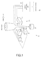
- Fig. 1 is a schematic diagram illustrating the structure of a flow cytometer 10 using the fluorescence detection device according to the present invention.
- the flow cytometer 10 includes a signal processing device 20 and an analyzing device 50.
- the signal processing device 20 detects and processes a fluorescent signal of fluorescence emitted by a fluorochrome in a sample 12 such as a microbead or a cell by irradiating the sample 12 with laser light.
- the analyzing device 50 analyzes a measurement object in the sample 12 from processing results obtained by the signal processing device 20.
- the signal processing device 20 includes a laser light source unit 22, light-receiving units 24, 25, and 26, a control/processing unit 28, and a tube 30.
- the control/processing unit 28 includes a light source control unit 40 (see Fig. 2 ) and an A/D converter 46 (see Fig. 2 ).
- the light source control unit 40 modulates the intensity of laser light emitted from the laser light source unit 22.
- the A/D converter 46 performs A/D conversion on a fluorescent signal from the sample 12.
- the tube 30 allows the sample 12 to flow therethrough together with a sheath liquid forming a high-speed flow so that a laminar sheath flow is formed.
- the laminar sheath flow has a diameter of, for example, 100 ⁇ m and a flow rate of 1 to 10 m/sec.
- the diameter of the microbead is several micrometers to 30 ⁇ m.
- a collection vessel 32 is provided under the outlet of the tube 30.
- the laser light source unit 22 is a unit that emits laser light whose intensity is modulated at a predetermined frequency.
- a lens system is provided so that laser light is focused on a predetermined position in the tube 30.
- the focus position is defined as a measurement point at which the sample 12 is measured.
- the laser light source unit 22 emits CW (continuous-wave) laser light of constant intensity while modulating the intensity of the CW laser light.
- Laser light emitted from the laser light source unit 22 is focused by the lens system (not illustrated) on the measurement point in the tube 30.
- a light source that emits laser light is, for example, a semiconductor laser.
- the laser light has an output of, for example, about 5 to 100 mW and a wavelength of, for example, 350 nm to 800 nm.
- the laser light source unit 22 is connected to the control/processing unit 28.
- the control/processing unit 28 supplies a modulation signal modulated at a predetermined frequency to the laser light source unit 22 to modulate the intensity of laser light.
- the fluorochrome to be excited by laser light is attached to the sample 12 such as a biological material or microbead to be measured.
- the sample 12 is irradiated with laser light at the measurement point and emits fluorescence in several to several tens of microseconds during which the sample 12 passes through the measurement point on which laser light is focused.
- a beam splitter 23 is provided between the laser light source unit 22 and the tube 30. Part of laser light emitted from the laser light source unit 22 passes through the beam splitter 23 and illuminates the sample 12 passing through the measurement point. Further, part of laser light emitted from the laser light source unit 22 is reflected by the beam splitter 23 and illuminates the light-receiving unit 25.
- the light-receiving unit 24 is arranged so as to be opposed to the laser light source unit 22 with the tube 30 provided therebetween. Laser light that has passed through the beam splitter 23 is forward-scattered by the sample 12 passing through the measurement point.
- the light-receiving unit 24 is equipped with a photoelectric converter that outputs a detection signal indicating the passage of the sample 12 through the measurement point.
- the signal output from the light-receiving unit 24 is supplied to the control/processing unit 28, and is used in the control/processing unit 28 as a trigger signal to announce the timing of passage of the sample 12 through the measurement point in the tube 30.
- the light-receiving unit 25 is arranged so as to receive part of laser light reflected by the beam splitter 23.
- the light-receiving unit 25 is equipped with a photoelectric converter that receives laser light reflected by the beam splitter 23 and outputs a signal of received light.
- the signal output from the light-receiving unit 25 is a signal corresponding to modulation of laser light, and is supplied to the control/processing unit 28.
- the signal supplied from the light-receiving unit 25 to the control/processing unit 28 is used as a reference signal to determine a phase difference from the fluorescent signal.
- the light-receiving unit 26 is arranged in a direction perpendicular to a direction in which laser light emitted from the laser light source unit 22 travels and to a direction in which the sample 12 moves in the tube 30.
- the sample 12 passing through the measurement point is irradiated with laser light that has passed through the beam splitter 23.
- the light-receiving unit 26 is equipped with a photoelectric converter that receives fluorescence emitted by the sample 12.
- the photoelectric converter converts light received by its photoelectric surface into an electrical signal (light-receiving signal).
- the light-receiving signal is supplied to the control/processing unit 28. For example, when fluorescence received by the light-receiving unit 26 is very weak and therefore pulsed signals each corresponding to a single photon are acquired, a light-receiving signal composed of two or more very weak pulsed fluorescent signals is output.
- Fig. 2 is a schematic diagram illustrating the structure of one example of the control/processing unit 28.
- the control/processing unit 28 includes the light source control unit 40 and the A/D converter 46.
- the light source control unit 40 includes an oscillator 42 and an amplifier 44.
- the light source control unit 40 generates a modulation signal for modulating the intensity of laser light and supplies the generated modulation signal to the laser light source unit 22.
- the oscillator 42 outputs a sinusoidal signal of a predetermined frequency.
- the frequency of the sinusoidal signal is set to a value in the range of, for example, 1 to 50 MHz.
- the sinusoidal signal of a predetermined frequency output from the oscillator 42 is amplified by the amplifier 44 and is supplied to the laser light source unit 22.
- the A/D converter 46 performs A/D conversion on the light-receiving signal output from the light-receiving unit 26 and the reference signal supplied from the light-receiving unit 25.
- the A/D conversion is started based on the trigger signal supplied from the light-receiving unit 24.
- As the A/D converter 46 one that performs sampling at several gigahertz is used. As will be described below, this makes it possible to, when fluorescence is weak, obtain a light-receiving signal composed of discrete pulsed fluorescent signals.
- the A/D converted light-receiving signal is supplied to the analyzing device 50.
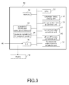
- Fig. 3 is a schematic diagram illustrating the structure of one example of the analyzing device 50.
- the analyzing device 50 is a device provided by executing a predetermined program on a computer.
- the analyzing device 50 includes a CPU 52, a memory 54, and an input/output port 70, and further includes a reference timing setting unit 56, a pulse generation time acquisition unit 58, a cumulative fluorescent signal generation unit 60, a correlation value calculation unit 62, a maximum correlation time acquisition unit 64, a phase difference calculation unit 66, and a fluorescence relaxation time calculation unit 68.
- the analyzing device 50 is connected to a display 80.
- the CPU 52 is an arithmetic processor provided in the computer to virtually make various calculations of the reference timing setting unit 56, the pulse generation time acquisition unit 58, the cumulative fluorescent signal generation unit 60, the correlation value calculation unit 62, the maximum correlation time acquisition unit 64, the phase difference calculation unit 66, and the fluorescence relaxation time calculation unit 68.
- the memory 54 includes a hard disk or ROM that stores a program to be executed on the computer to provide the reference timing setting unit 56, the pulse generation time acquisition unit 58, the cumulative fluorescent signal generation unit 60, the correlation value calculation unit 62, the maximum correlation time acquisition unit 64, the phase difference calculation unit 66, and the fluorescence relaxation time calculation unit 68 and a RAM that stores processing results calculated by these units and signals supplied from the input/output port 70.
- the memory 54 continuously stores the light-receiving signal and the reference signal supplied from the A/D converter 46.
- the input/output port 70 is used to receive the reference signal and the light-receiving signal supplied from the A/D converter 46 and to output information about the processing results generated by the units to the display 80.
- the display 80 displays the values of the processing results determined by the units such as a pulse generation time, a cumulative fluorescent signal, a correlation value, a maximum correlation time, a phase difference, and a fluorescence relaxation time.
- Figs. 4(a) and 4(b) are graphs each illustrating one example of the signal stored in the memory 54 of the analyzing device.
- Fig. 4(a) is a graph illustrating one example of the reference signal supplied from the light-receiving unit 25 to the A/D converter 46 and stored in the memory 54.
- Fig. 4(b) is a graph illustrating one example of the light-receiving signal supplied from the light-receiving unit 26 to the A/D converter 46 and stored in the memory 54.
- the reference timing setting unit 56 sets reference timing (ti: i is an integer) at a constant time interval for the light-receiving signal and the reference signal stored in the memory 54.
- the time interval is set to a period corresponding to a frequency at which laser light is modulated. For example, when laser light is modulated at a frequency of 10 MHz, the time interval is set to 100 nsec that is a period corresponding to 10 MHz.
- the signals illustrated in Figs. 4(a) and 4(b) are examples in which the reference timing is set per period (one cycle) corresponding to a frequency at which laser light is modulated, but the reference timing may be set per unit such as per two cycles or three cycles.
- the pulse generation time acquisition unit 58 acquires, based on the reference timing ti, a pulse generation time that is the time to output of each pulsed fluorescent signal.
- a pulse generation time that is the time to output of each pulsed fluorescent signal.
- three pulsed fluorescent signals are measured between the reference timing t0 and the reference timing t1.
- the pulse generation time acquisition unit 58 acquires the time (generation time) from the reference timing t0 to generation of each of the three pulsed fluorescent signals. Between the reference timing t1 and the reference timing t2, one pulsed fluorescent signal is measured.
- the pulse generation time acquisition unit 58 acquires the time (generation time) from the reference timing t1 to generation of the fluorescent signal. In this way, the pulse generation time acquisition unit 58 acquires the time (generation time) from the reference timing ti to output of each pulsed fluorescent signal.
- the time (generation time) to generation of a pulsed fluorescent signal is acquired as the time in the middle between the time when a pulsed electrical signal exceeds a predetermined threshold value and the time when the pulsed electrical signal falls below the threshold value.
- the threshold value is set to prevent a noise component from being acquired by mistake as a pulsed fluorescent signal.
- the cumulative fluorescent signal generation unit 60 determines a cumulative fluorescent signal that indicates the relationship between the pulse generation time determined by the pulse generation time acquisition unit 58 and the frequency of output of a pulsed fluorescent signal at the pulse generation time.
- Fig. 5(b) is a graph illustrating one example of the cumulative fluorescent signal acquired by the cumulative fluorescent signal generation unit 60 of the analyzing device 50.
- the cumulative fluorescent signal generation unit 60 divides the pulse generation time determined by the pulse generation time acquisition unit 58 into two or more time zones and calculates the frequency of generation of a pulse per time zone.
- the cumulative fluorescent signal generation unit 60 generates, when the time of the reference timing is set to time 0, a cumulative fluorescent signal obtained by representing, as a signal value, the frequency of generation of a pulsed fluorescent signal at the time in the middle of the time zone.
- the cumulative fluorescent signal is a signal represented by a histogram illustrated in Fig. 5(b) . It should be understood that it is possible to generate a cumulative fluorescent signal represented by a histogram in which the difference in height between adjacent bars is smaller by setting the width of the time zones to a smaller value. However, in this case, the parameter of a fluorescent signal to be cumulated is small, and therefore noise is likely to be generated. For this reason, it is preferred that the setting of width of the time zones is previously searched and determined so that a continuous and smooth cumulative fluorescent signal can be generated.
- the correlation value calculation unit 62 determines a correlation value between the cumulative fluorescent signal determined by the cumulative fluorescent signal generation unit 60 and the reference signal.
- the reference signal used to calculate a correlation value is a signal during one cycle divided by the reference timing. Such a signal during one cycle may be obtained by averaging a stored reference signal or by selecting one reference signal during one cycle as a representative.
- Fig. 5(a) is a graph illustrating one example of the reference signal during one cycle.
- the correlation value calculation unit 62 acquires a correlation value between the reference signal and the cumulative fluorescent signal by shifting the reference signal in the direction of time. Fig.
- 5(c) is a graph illustrating one example of a signal of the correlation value acquired by the correlation value calculation unit 62 of the analyzing device 50, wherein the horizontal axis represents the time during which the reference signal is shifted in the direction of time and the vertical axis represents the correlation value.
- the maximum correlation time acquisition unit 64 determines the time ⁇ t (maximum correlation time) when the correlation value determined by the correlation value calculation unit 62 is maximized.
- the phase difference calculation unit 66 determines a phase difference between the reference signal and the cumulative fluorescent signal by using the maximum correlation time ⁇ t determined by the maximum correlation time acquisition unit 64.
- the fluorescence relaxation time calculation unit 68 determines a fluorescence relaxation time ⁇ of the fluorescence emitted by the measurement object by using the phase difference ⁇ determined by the phase difference calculation unit 66.
- Fig. 6 is a flow chart of the fluorescence detection method according to this embodiment.
- the laser light source unit 22 irradiates a measurement object with laser light modulated at a predetermined frequency (S101).
- the light-receiving unit 26 receives fluorescence emitted by the measurement object and outputs a light-receiving signal including two or more pulsed fluorescent signals (S102).
- the reference timing setting unit 56 sets reference timing in units of period corresponding to the frequency (S103).
- the pulse generation time acquisition unit 58 acquires, based on the reference timing, a generation time to output of each of the pulsed fluorescent signals (S104). Then, the cumulative fluorescent signal generation unit 60 generates a cumulative fluorescent signal indicating the relationship between the generation frequency of the pulsed fluorescent signal and the generation time (S105). Then, the correlation value calculation unit 62 determines a correlation value between the cumulative fluorescent signal and a reference signal (S106). Then, the maximum correlation time acquisition unit 64 acquires a maximum correlation time at which the correlation value determined by the correlation value calculation unit 62 is maximized (S107).
- the phase difference calculation unit 66 determines, by using a signal corresponding to modulation of the laser light as a reference signal, a phase difference between the cumulative fluorescent signal and the reference signal (S108). Then, the fluorescence relaxation time calculation unit 68 determines a fluorescence relaxation time of the fluorescence emitted by the measurement object by using the phase difference determined by the phase difference calculation unit 66 (S 109).
- a program according to this embodiment is a program for causing a computer to execute the processing of two or more pulsed fluorescent signals obtained as a light-receiving signal of fluorescence emitted by a measurement obj ect irradiated with laser light modulated at a predetermined frequency.
- This program causes a computer to execute the step of setting reference timing in units of period corresponding to the frequency, the step of acquiring, based on the reference timing, a generation time to output of each of the pulsed fluorescent signals, the step of generating a cumulative fluorescent signal indicating the relationship between the generation frequency of the pulsed fluorescent signal and the generation time, the step of determining, by using a signal corresponding to modulation of the laser light as a reference signal, a phase difference between the cumulative fluorescent signal and the reference signal, and the step of determining a fluorescence relaxation time of the fluorescence emitted by the measurement obj ect by using the phase difference.
- This program is stored in the memory 54 of the analyzing device 50.
- a fluorescence relaxation time can be measured with high accuracy by using a cumulative fluorescent signal.
- a signal obtained by reflecting part of laser light emitted from the laser light source unit 22 on the beam splitter 23 and receiving the reflected laser light by the light-receiving unit 25 is used as a reference signal.
- a second embodiment is different from the first embodiment in that the beam splitter 23 and the light-receiving unit 25 are omitted, and a modulation signal output from the light source control unit 40 is supplied to both the laser light source unit 22 and the A/D converter 46, and the modulation signal supplied from the light source control unit 40 to the A/D converter 46 is used as a reference signal.
- a power splitter is used in the light source control unit 40 to split the modulation signal.
- the other structures of the second embodiment are the same as those of the first embodiment.
- the reference signal and the fluorescent signal supplied from the A/D converter 46 to the input/output port 70 are stored in the memory 54.
- a third embodiment is different from the first embodiment in that the reference signal and the fluorescent signal supplied from the A/D converter 46 to the input/output port 70 are not stored in the memory 54 but are directly subjected to subsequent signal processing.
- the sinusoidal signal output by the light source control unit 40 has a predetermined frequency f. Therefore, the reference timing setting unit 56 sets reference timing in units of period corresponding to the frequency f for the reference signal and the fluorescent signal supplied to the input/output port 70.
- the pulse generation time acquisition unit 58 acquires, based on the reference timing, the time (generation time) to generation of each of the pulsed fluorescent signals. Information about the generation time is stored in the memory 54. Then, a cumulative fluorescent signal is determined using the information about the generation time in the same manner as in the first embodiment, and thereafter the same processing as the first embodiment is performed.
- a fluorescence relaxation time can be measured with high accuracy by a smaller memory capacity.
- the correlation value calculation unit 62 determines a correlation value between the cumulative fluorescent signal and the reference signal by using the cumulative fluorescent signal determined by the cumulative fluorescent signal generation unit 60.
- a fourth embodiment is different from the first embodiment in that a correlation value between the cumulative fluorescent signal and the reference signal is not determined but a phase difference between the reference signal and the cumulative fluorescent signal is determined.
- Fig. 7 is a schematic diagram illustrating the structure of one example of the analyzing device 50 of this embodiment. The structure of this embodiment is the same as that of the first embodiment except that the correlation value calculation unit 62 and the maximum correlation time acquisition unit 64 provided in the first embodiment are omitted.
- the cumulative fluorescent signal generation unit 60 divides the pulse generation time determined by the pulse generation time acquisition unit 58 into two or more time zones and calculates a pulse generation frequency per time zone to generate a cumulative fluorescent signal. Further, the cumulative fluorescent signal generation unit 60 of this embodiment determines a delay time of the cumulative fluorescent signal with respect to the modulation signal by performing fitting of the cumulative fluorescent signal to a signal (sinusoidal signal) having the same shape as the modulation signal for modulating laser light. The fitting is performed by, for example, the method of least squares. In Fig. 5(b) , the dotted line represents a signal obtained by fitting of the cumulative fluorescent signal.
- the phase difference calculation unit 66 determines, by using the cumulative fluorescent signal determined by the cumulative fluorescent signal generation unit 60, a delay time ⁇ t of the cumulative fluorescent signal with respect to the modulation signal, and further determines a phase difference from the delay time ⁇ t.
- Fig. 8 is a flow chart of the fluorescence detection method according to this embodiment.
- the laser light source unit 22 irradiates a measurement object with laser light modulated at a predetermined frequency (S201).
- the light-receiving unit 26 receives fluorescence emitted by the measurement object and outputs a light-receiving signal including two or more pulsed fluorescent signals (S202).
- the reference timing setting unit 56 sets reference timing in units of period corresponding to the frequency (S203).
- the pulse generation time acquisition unit 58 acquires, based on the reference timing, a generation time to output of each of the pulsed fluorescent signals (S204).
- the cumulative fluorescent signal generation unit 60 generates a cumulative fluorescent signal indicating the relationship between the generation frequency of the pulsed fluorescent signal and the generation time (S205).
- the phase difference calculation unit 66 determines, by using a signal corresponding to modulation of the laser light as a reference signal, a phase difference between the reference signal and the cumulative fluorescent signal (S206).
- the fluorescence relaxation time calculation unit 68 determines, by using the phase difference determined by the phase difference calculation unit 66, a fluorescence relaxation time of the fluorescence emitted by the measurement object (S207).
- a fluorescence relaxation time can be determined with high accuracy by a simpler structure.
Landscapes
- Health & Medical Sciences (AREA)
- Chemical & Material Sciences (AREA)
- Immunology (AREA)
- Physics & Mathematics (AREA)
- Life Sciences & Earth Sciences (AREA)
- Analytical Chemistry (AREA)
- Biochemistry (AREA)
- General Health & Medical Sciences (AREA)
- General Physics & Mathematics (AREA)
- Nuclear Medicine, Radiotherapy & Molecular Imaging (AREA)
- Pathology (AREA)
- Chemical Kinetics & Catalysis (AREA)
- Optics & Photonics (AREA)
- Investigating, Analyzing Materials By Fluorescence Or Luminescence (AREA)
Abstract
Disclosed herein is a fluorescence detection method. The fluorescence detection method includes the steps of: irradiating a measurement obj ect with laser light modulated at a predetermined frequency; receiving fluorescence emitted by the measurement object and outputting two or more pulsed fluorescent signals; setting reference timing in units of period corresponding to the frequency; acquiring a generation time to output of each of the pulsed fluorescent signals based on the reference timing; generating a cumulative fluorescent signal indicating the relationship between a generation frequency of the pulsed fluorescent signal and the generation time; determining, by using a signal corresponding to modulation of the laser light as a reference signal, a phase difference between the reference signal and the cumulative fluorescent signal; and determining, by using the phase difference, a fluorescence relaxation time of the fluorescence emitted by the measurement object.
Description
- The present invention relates to a method and a device for detecting fluorescence by receiving fluorescence emitted by a measurement object irradiated with laser light and processing a fluorescent signal obtained at this time. The present invention also relates to a program for causing a computer to perform processing of two or more pulsed fluorescent signals obtained as a light-receiving signal of fluorescence emitted by a measurement object irradiated with laser light modulated at a predetermined frequency.
- Particularly, the present invention relates to a fluorescence detection device to be applied to an analyzing device, such as a flow cytometer for use in medical and biological fields, which identifies and analyzes a measurement object such as cells, DNA, or RNA by using fluorescence emitted by a fluorochrome.
- A flow cytometer for use in medical and biological fields includes a fluorescence detection device that receives fluorescence emitted by a fluorochrome of a measurement object irradiated with laser light and identifies the kind of the measurement object.
- More specifically, in the flow cytometer, a suspension liquid containing a measurement object such as a biological material (e.g., cells, DNA, RNA, enzymes, or proteins) labeled with a fluorescent reagent is allowed to flow through a tube together with a sheath liquid flowing under pressure at a speed of about 10 m/sec or less to form a laminar sheath flow. The flow cytometer receives fluorescence emitted by a fluorochrome attached to the measurement object by irradiating the measurement object in the laminar sheath flow with laser light and identifies the measurement object by using the fluorescence as a label.
- The flow cytometer can measure, for example, the relative amounts of DNA, RNA, enzymes, proteins, etc. contained in a cell and can quickly analyze their functions. Further, a cell sorter or the like is used to identify a specific type of cell or chromosome based on fluorescence and selectively and quickly collect only the identified cells or chromosomes alive.
- For example, in order to analyze a biological material such as DNA by a flow cytometer, a fluorochrome is previously attached to the biological material by a fluorescent reagent. The biological material is labeled with a fluorochrome different from a fluorochrome attached to a microbead (which will be described later) and is mixed with a liquid containing microbeads having a diameter of 5 to 20 µm and a specific structure such as a carboxyl group provided on the surface thereof. The structure such as a carboxyl group acts on and is coupled to a biological material having a certain known structure. Therefore, simultaneous detection of fluorescence emitted by the microbead and fluorescence emitted by the biological material indicates that the biological material has been coupled to the structure provided on the surface of the microbead. This makes it possible to analyze the characteristics of the biological material. In order to quickly analyze the characteristics of a biological material by using various microbeads having different structures for coupling, very many kinds of fluorochromes are required.
- Patent Document 1 describes that a fluorescence relaxation time of fluorescence emitted by irradiating a measurement object such as a microbead with laser light whose intensity is modulated at a predetermined frequency is determined. The fluorescence relaxation time varies depending on the type of fluorochrome used, and therefore the type of the fluorescence can be identified using the fluorescence relaxation time and the type of the measurement object can be identified by identifying the type of the fluorescence.
-
- Patent Document 1: Japanese Patent Application Laid-Open No.
2006-226698 - According to Patent Document 1, it is possible to efficiently and quickly identify fluorescence based on a fluorescence relaxation time, but the measurement accuracy of a fluorescence relaxation time is not always high. For example, when received fluorescence is weak and therefore a light-receiving signal is composed of two or more discrete pulsed fluorescent signals, a phase difference required to determine a fluorescence relaxation time cannot be determined.
- In order to solve the above problem, it is an object of the present invention to provide a fluorescence detection method, a fluorescence detection device, and a program therefor which make it possible to determine a fluorescence relaxation time with high accuracy even when fluorescence is weak and a light-receiving signal thereof is composed of two or more discrete pulsed fluorescent signals.
- A method of the present invention for detecting fluorescence by receiving fluorescence emitted by a measurement object irradiated with laser light and processing a fluorescent signal obtained at this time, the method comprising the steps of: irradiating the measurement object with laser light modulated at a predetermined frequency; receiving fluorescence emitted by the measurement object and outputting two or more pulsed fluorescent signals; setting reference timing in units of period corresponding to the frequency; acquiring a generation time to output of each of the pulsed fluorescent signals based on the reference timing; generating a cumulative fluorescent signal indicating a relationship between a generation frequency of the pulsed fluorescent signal and the generation time; determining, by using a signal corresponding to modulation of the laser light as a reference signal, a phase difference between the reference signal and the cumulative fluorescent signal; and determining, by using the phase difference, a fluorescence relaxation time of the fluorescence emitted by the measurement object.
- A device of the present invention for detecting fluorescence by receiving fluorescence emitted by a measurement object irradiated with laser light and processing a fluorescent signal obtained at this time, the device comprising: a laser light source unit that irradiates a measurement object with laser light modulated at a predetermined frequency; a light-receiving unit that receives fluorescence emitted by the measurement object and outputs two or more pulsed fluorescent signals; and a processing unit that determines, by using the fluorescent signals output by the light-receiving unit by irradiation of the measurement object with the laser light, a fluorescence relaxation time of the fluorescence emitted by the measurement object, wherein the processing unit comprises: a reference timing setting unit that sets reference timing in units of period corresponding to the frequency; a pulse generation time acquisition unit that acquires a generation time to output of each of the pulsed fluorescent signals based on the reference timing; a cumulative fluorescent signal generation unit that generates a cumulative fluorescent signal indicating a relationship between a generation frequency of the pulsed fluorescent signal and the pulse generation time; a phase difference acquisition unit that determines, by using a signal corresponding to modulation of the laser light as a reference signal, a phase difference between the reference signal and the cumulative fluorescent signal; and a fluorescence relaxation time acquisition unit that determines, by using the phase difference determined by the phase difference acquisition unit, a fluorescence relaxation time of the fluorescence emitted by the measurement obj ect.
- A program of the present invention for causing a computer to execute processing of two or more pulsed fluorescent signals obtained as a light-receiving signal of fluorescence emitted by a measurement object irradiated with laser light modulated at a predetermined frequency, the computer executing the steps of: setting reference timing in units of period corresponding to the frequency; acquiring a generation time to output of each of the pulsed fluorescent signals based on the reference timing; generating a cumulative fluorescent signal indicating a relationship between a generation frequency of the pulsed fluorescent signal and the generation time; determining, by using a signal corresponding to modulation of the laser light as a reference signal, a phase difference between the reference signal and the cumulative fluorescent signal; and determining, by using the phase difference, a fluorescence relaxation time of the fluorescence emitted by the measurement object.
- According to the present invention, it is possible to determine a fluorescence relaxation time with high accuracy.
-
-
Fig. 1 is a schematic diagram illustrating the structure of a flow cytometer according to one embodiment of a fluorescence detection device of the present invention. -
Fig. 2 is a schematic diagram illustrating the structure of one example of a control/processing unit for use in the fluorescence detection device illustrated inFig. 1 . -
Fig. 3 is a schematic diagram illustrating the structure of one example of an analyzing device for use in the fluorescence detection device illustrated inFig. 1 . -
Figs. 4(a) and 4(b) are graphs each illustrating one example of a signal stored in a memory of the analyzing device illustrated inFig. 1 . -
Fig. 5(a) is a graph illustrating one example of a reference signal obtained by the fluorescence detection device illustrated inFig. 1 ,Fig. 5(b) is a graph illustrating one example of a signal acquired by a cumulative fluorescent signal generation unit of the analyzing device illustrated inFig. 3 , andFig. 5(c) is a graph illustrating one example of a signal acquired by a correlation value calculation unit of the analyzing device. -
Fig. 6 is a flow chart of one embodiment of a fluorescence detection method according to the present invention. -
Fig. 7 is a schematic diagram illustrating the structure of another example of the analyzing device for use in the fluorescence detection device illustrated inFig. 1 . -
Fig. 8 is a flow chart of another embodiment of the fluorescence detection method according to the present invention. - Hereinbelow, a flow cytometer appropriately using a fluorescence detection device according to the present invention will be described in detail based on the following embodiments.
- The overall structure of a flow cytometer according to a first embodiment will be described first with reference to
Fig. 1. Fig. 1 is a schematic diagram illustrating the structure of a flow cytometer 10 using the fluorescence detection device according to the present invention. - The flow cytometer 10 includes a
signal processing device 20 and ananalyzing device 50. Thesignal processing device 20 detects and processes a fluorescent signal of fluorescence emitted by a fluorochrome in asample 12 such as a microbead or a cell by irradiating thesample 12 with laser light. The analyzingdevice 50 analyzes a measurement object in thesample 12 from processing results obtained by thesignal processing device 20. - The
signal processing device 20 includes a laserlight source unit 22, light-receiving units processing unit 28, and atube 30. The control/processing unit 28 includes a light source control unit 40 (seeFig. 2 ) and an A/D converter 46 (seeFig. 2 ). The lightsource control unit 40 modulates the intensity of laser light emitted from the laserlight source unit 22. The A/D converter 46 performs A/D conversion on a fluorescent signal from thesample 12. Thetube 30 allows thesample 12 to flow therethrough together with a sheath liquid forming a high-speed flow so that a laminar sheath flow is formed. The laminar sheath flow has a diameter of, for example, 100 µm and a flow rate of 1 to 10 m/sec. When a microbead is used as thesample 12, the diameter of the microbead is several micrometers to 30 µm. Acollection vessel 32 is provided under the outlet of thetube 30. - The laser
light source unit 22 is a unit that emits laser light whose intensity is modulated at a predetermined frequency. A lens system is provided so that laser light is focused on a predetermined position in thetube 30. The focus position is defined as a measurement point at which thesample 12 is measured. - The laser
light source unit 22 emits CW (continuous-wave) laser light of constant intensity while modulating the intensity of the CW laser light. Laser light emitted from the laserlight source unit 22 is focused by the lens system (not illustrated) on the measurement point in thetube 30. - A light source that emits laser light is, for example, a semiconductor laser. The laser light has an output of, for example, about 5 to 100 mW and a wavelength of, for example, 350 nm to 800 nm.
- The laser
light source unit 22 is connected to the control/processing unit 28. The control/processing unit 28 supplies a modulation signal modulated at a predetermined frequency to the laserlight source unit 22 to modulate the intensity of laser light. - The fluorochrome to be excited by laser light is attached to the
sample 12 such as a biological material or microbead to be measured. Thesample 12 is irradiated with laser light at the measurement point and emits fluorescence in several to several tens of microseconds during which thesample 12 passes through the measurement point on which laser light is focused. - A
beam splitter 23 is provided between the laserlight source unit 22 and thetube 30. Part of laser light emitted from the laserlight source unit 22 passes through thebeam splitter 23 and illuminates thesample 12 passing through the measurement point. Further, part of laser light emitted from the laserlight source unit 22 is reflected by thebeam splitter 23 and illuminates the light-receivingunit 25. - The light-receiving
unit 24 is arranged so as to be opposed to the laserlight source unit 22 with thetube 30 provided therebetween. Laser light that has passed through thebeam splitter 23 is forward-scattered by thesample 12 passing through the measurement point. The light-receivingunit 24 is equipped with a photoelectric converter that outputs a detection signal indicating the passage of thesample 12 through the measurement point. The signal output from the light-receivingunit 24 is supplied to the control/processing unit 28, and is used in the control/processing unit 28 as a trigger signal to announce the timing of passage of thesample 12 through the measurement point in thetube 30. - The light-receiving
unit 25 is arranged so as to receive part of laser light reflected by thebeam splitter 23. The light-receivingunit 25 is equipped with a photoelectric converter that receives laser light reflected by thebeam splitter 23 and outputs a signal of received light. The signal output from the light-receivingunit 25 is a signal corresponding to modulation of laser light, and is supplied to the control/processing unit 28. The signal supplied from the light-receivingunit 25 to the control/processing unit 28 is used as a reference signal to determine a phase difference from the fluorescent signal. - The light-receiving
unit 26 is arranged in a direction perpendicular to a direction in which laser light emitted from the laserlight source unit 22 travels and to a direction in which thesample 12 moves in thetube 30. Thesample 12 passing through the measurement point is irradiated with laser light that has passed through thebeam splitter 23. The light-receivingunit 26 is equipped with a photoelectric converter that receives fluorescence emitted by thesample 12. - The photoelectric converter converts light received by its photoelectric surface into an electrical signal (light-receiving signal). The light-receiving signal is supplied to the control/
processing unit 28. For example, when fluorescence received by the light-receivingunit 26 is very weak and therefore pulsed signals each corresponding to a single photon are acquired, a light-receiving signal composed of two or more very weak pulsed fluorescent signals is output. -
Fig. 2 is a schematic diagram illustrating the structure of one example of the control/processing unit 28. As described above, the control/processing unit 28 includes the lightsource control unit 40 and the A/D converter 46. - The light
source control unit 40 includes anoscillator 42 and anamplifier 44. The lightsource control unit 40 generates a modulation signal for modulating the intensity of laser light and supplies the generated modulation signal to the laserlight source unit 22. - The
oscillator 42 outputs a sinusoidal signal of a predetermined frequency. The frequency of the sinusoidal signal is set to a value in the range of, for example, 1 to 50 MHz. The sinusoidal signal of a predetermined frequency output from theoscillator 42 is amplified by theamplifier 44 and is supplied to the laserlight source unit 22. - The A/
D converter 46 performs A/D conversion on the light-receiving signal output from the light-receivingunit 26 and the reference signal supplied from the light-receivingunit 25. The A/D conversion is started based on the trigger signal supplied from the light-receivingunit 24. As the A/D converter 46, one that performs sampling at several gigahertz is used. As will be described below, this makes it possible to, when fluorescence is weak, obtain a light-receiving signal composed of discrete pulsed fluorescent signals. The A/D converted light-receiving signal is supplied to the analyzingdevice 50. -
Fig. 3 is a schematic diagram illustrating the structure of one example of the analyzingdevice 50. The analyzingdevice 50 is a device provided by executing a predetermined program on a computer. The analyzingdevice 50 includes aCPU 52, amemory 54, and an input/output port 70, and further includes a referencetiming setting unit 56, a pulse generationtime acquisition unit 58, a cumulative fluorescentsignal generation unit 60, a correlationvalue calculation unit 62, a maximum correlationtime acquisition unit 64, a phasedifference calculation unit 66, and a fluorescence relaxationtime calculation unit 68. The analyzingdevice 50 is connected to adisplay 80. - The
CPU 52 is an arithmetic processor provided in the computer to virtually make various calculations of the referencetiming setting unit 56, the pulse generationtime acquisition unit 58, the cumulative fluorescentsignal generation unit 60, the correlationvalue calculation unit 62, the maximum correlationtime acquisition unit 64, the phasedifference calculation unit 66, and the fluorescence relaxationtime calculation unit 68. - The
memory 54 includes a hard disk or ROM that stores a program to be executed on the computer to provide the referencetiming setting unit 56, the pulse generationtime acquisition unit 58, the cumulative fluorescentsignal generation unit 60, the correlationvalue calculation unit 62, the maximum correlationtime acquisition unit 64, the phasedifference calculation unit 66, and the fluorescence relaxationtime calculation unit 68 and a RAM that stores processing results calculated by these units and signals supplied from the input/output port 70. Thememory 54 continuously stores the light-receiving signal and the reference signal supplied from the A/D converter 46. - The input/
output port 70 is used to receive the reference signal and the light-receiving signal supplied from the A/D converter 46 and to output information about the processing results generated by the units to thedisplay 80. Thedisplay 80 displays the values of the processing results determined by the units such as a pulse generation time, a cumulative fluorescent signal, a correlation value, a maximum correlation time, a phase difference, and a fluorescence relaxation time. -
Figs. 4(a) and 4(b) are graphs each illustrating one example of the signal stored in thememory 54 of the analyzing device.Fig. 4(a) is a graph illustrating one example of the reference signal supplied from the light-receivingunit 25 to the A/D converter 46 and stored in thememory 54.Fig. 4(b) is a graph illustrating one example of the light-receiving signal supplied from the light-receivingunit 26 to the A/D converter 46 and stored in thememory 54. When the light-receivingunit 26 receives such weak light that a pulsed fluorescent signal is acquired every time one photon is received, as illustrated inFig. 4(b) , each individual fluorescent signal is measured as a pulsed electrical signal. - The reference
timing setting unit 56 sets reference timing (ti: i is an integer) at a constant time interval for the light-receiving signal and the reference signal stored in thememory 54. The time interval is set to a period corresponding to a frequency at which laser light is modulated. For example, when laser light is modulated at a frequency of 10 MHz, the time interval is set to 100 nsec that is a period corresponding to 10 MHz. The signals illustrated inFigs. 4(a) and 4(b) are examples in which the reference timing is set per period (one cycle) corresponding to a frequency at which laser light is modulated, but the reference timing may be set per unit such as per two cycles or three cycles. - The pulse generation
time acquisition unit 58 acquires, based on the reference timing ti, a pulse generation time that is the time to output of each pulsed fluorescent signal. In the case of the example illustrated inFig. 4(b) , three pulsed fluorescent signals are measured between the reference timing t0 and the reference timing t1. The pulse generationtime acquisition unit 58 acquires the time (generation time) from the reference timing t0 to generation of each of the three pulsed fluorescent signals. Between the reference timing t1 and the reference timing t2, one pulsed fluorescent signal is measured. The pulse generationtime acquisition unit 58 acquires the time (generation time) from the reference timing t1 to generation of the fluorescent signal. In this way, the pulse generationtime acquisition unit 58 acquires the time (generation time) from the reference timing ti to output of each pulsed fluorescent signal. - The time (generation time) to generation of a pulsed fluorescent signal is acquired as the time in the middle between the time when a pulsed electrical signal exceeds a predetermined threshold value and the time when the pulsed electrical signal falls below the threshold value. The threshold value is set to prevent a noise component from being acquired by mistake as a pulsed fluorescent signal.
- The cumulative fluorescent
signal generation unit 60 determines a cumulative fluorescent signal that indicates the relationship between the pulse generation time determined by the pulse generationtime acquisition unit 58 and the frequency of output of a pulsed fluorescent signal at the pulse generation time.Fig. 5(b) is a graph illustrating one example of the cumulative fluorescent signal acquired by the cumulative fluorescentsignal generation unit 60 of the analyzingdevice 50. The cumulative fluorescentsignal generation unit 60 divides the pulse generation time determined by the pulse generationtime acquisition unit 58 into two or more time zones and calculates the frequency of generation of a pulse per time zone. - Further, the cumulative fluorescent
signal generation unit 60 generates, when the time of the reference timing is set to time 0, a cumulative fluorescent signal obtained by representing, as a signal value, the frequency of generation of a pulsed fluorescent signal at the time in the middle of the time zone. For example, the cumulative fluorescent signal is a signal represented by a histogram illustrated inFig. 5(b) . It should be understood that it is possible to generate a cumulative fluorescent signal represented by a histogram in which the difference in height between adjacent bars is smaller by setting the width of the time zones to a smaller value. However, in this case, the parameter of a fluorescent signal to be cumulated is small, and therefore noise is likely to be generated. For this reason, it is preferred that the setting of width of the time zones is previously searched and determined so that a continuous and smooth cumulative fluorescent signal can be generated. - The correlation
value calculation unit 62 determines a correlation value between the cumulative fluorescent signal determined by the cumulative fluorescentsignal generation unit 60 and the reference signal. The reference signal used to calculate a correlation value is a signal during one cycle divided by the reference timing. Such a signal during one cycle may be obtained by averaging a stored reference signal or by selecting one reference signal during one cycle as a representative.Fig. 5(a) is a graph illustrating one example of the reference signal during one cycle. The correlationvalue calculation unit 62 acquires a correlation value between the reference signal and the cumulative fluorescent signal by shifting the reference signal in the direction of time.Fig. 5(c) is a graph illustrating one example of a signal of the correlation value acquired by the correlationvalue calculation unit 62 of the analyzingdevice 50, wherein the horizontal axis represents the time during which the reference signal is shifted in the direction of time and the vertical axis represents the correlation value.
The maximum correlationtime acquisition unit 64 determines the time Δt (maximum correlation time) when the correlation value determined by the correlationvalue calculation unit 62 is maximized. - The phase
difference calculation unit 66 determines a phase difference between the reference signal and the cumulative fluorescent signal by using the maximum correlation time Δt determined by the maximum correlationtime acquisition unit 64. The phase difference θ is determined by θ=2πfΔt where f is the frequency of the modulation signal for modulating laser light. - The fluorescence relaxation
time calculation unit 68 determines a fluorescence relaxation time τ of the fluorescence emitted by the measurement object by using the phase difference θ determined by the phasedifference calculation unit 66. The fluorescence relaxation time τ is determined by τ=tan θ/(2πf). - Hereinbelow, a fluorescence detection method according to this embodiment will be described with reference to
Fig. 6. Fig. 6 is a flow chart of the fluorescence detection method according to this embodiment.
According to the fluorescence detection method of this embodiment, first, the laserlight source unit 22 irradiates a measurement object with laser light modulated at a predetermined frequency (S101). Then, the light-receivingunit 26 receives fluorescence emitted by the measurement object and outputs a light-receiving signal including two or more pulsed fluorescent signals (S102).
Then, the referencetiming setting unit 56 sets reference timing in units of period corresponding to the frequency (S103). Then, the pulse generationtime acquisition unit 58 acquires, based on the reference timing, a generation time to output of each of the pulsed fluorescent signals (S104). Then, the cumulative fluorescentsignal generation unit 60 generates a cumulative fluorescent signal indicating the relationship between the generation frequency of the pulsed fluorescent signal and the generation time (S105). Then, the correlationvalue calculation unit 62 determines a correlation value between the cumulative fluorescent signal and a reference signal (S106). Then, the maximum correlationtime acquisition unit 64 acquires a maximum correlation time at which the correlation value determined by the correlationvalue calculation unit 62 is maximized (S107). Then, the phasedifference calculation unit 66 determines, by using a signal corresponding to modulation of the laser light as a reference signal, a phase difference between the cumulative fluorescent signal and the reference signal (S108). Then, the fluorescence relaxationtime calculation unit 68 determines a fluorescence relaxation time of the fluorescence emitted by the measurement object by using the phase difference determined by the phase difference calculation unit 66 (S 109). - A program according to this embodiment is a program for causing a computer to execute the processing of two or more pulsed fluorescent signals obtained as a light-receiving signal of fluorescence emitted by a measurement obj ect irradiated with laser light modulated at a predetermined frequency. This program causes a computer to execute the step of setting reference timing in units of period corresponding to the frequency, the step of acquiring, based on the reference timing, a generation time to output of each of the pulsed fluorescent signals, the step of generating a cumulative fluorescent signal indicating the relationship between the generation frequency of the pulsed fluorescent signal and the generation time, the step of determining, by using a signal corresponding to modulation of the laser light as a reference signal, a phase difference between the cumulative fluorescent signal and the reference signal, and the step of determining a fluorescence relaxation time of the fluorescence emitted by the measurement obj ect by using the phase difference. This program is stored in the
memory 54 of the analyzingdevice 50. - According to this embodiment, even when fluorescence is weak and therefore a light-receiving signal is composed of two or more pulsed fluorescent signals, a fluorescence relaxation time can be measured with high accuracy by using a cumulative fluorescent signal.
- As described above, in the case of the first embodiment, a signal obtained by reflecting part of laser light emitted from the laser
light source unit 22 on thebeam splitter 23 and receiving the reflected laser light by the light-receivingunit 25 is used as a reference signal. A second embodiment is different from the first embodiment in that thebeam splitter 23 and the light-receivingunit 25 are omitted, and a modulation signal output from the lightsource control unit 40 is supplied to both the laserlight source unit 22 and the A/D converter 46, and the modulation signal supplied from the lightsource control unit 40 to the A/D converter 46 is used as a reference signal. In this case, a power splitter is used in the lightsource control unit 40 to split the modulation signal. The other structures of the second embodiment are the same as those of the first embodiment. - According to this embodiment, even when fluorescence is weak, a fluorescence relaxation time can be measured with high accuracy by a simpler structure.
- As described above, in the case of the first embodiment, the reference signal and the fluorescent signal supplied from the A/
D converter 46 to the input/output port 70 are stored in thememory 54. A third embodiment is different from the first embodiment in that the reference signal and the fluorescent signal supplied from the A/D converter 46 to the input/output port 70 are not stored in thememory 54 but are directly subjected to subsequent signal processing. - The sinusoidal signal output by the light
source control unit 40 has a predetermined frequency f. Therefore, the referencetiming setting unit 56 sets reference timing in units of period corresponding to the frequency f for the reference signal and the fluorescent signal supplied to the input/output port 70. - The pulse generation
time acquisition unit 58 acquires, based on the reference timing, the time (generation time) to generation of each of the pulsed fluorescent signals. Information about the generation time is stored in thememory 54.
Then, a cumulative fluorescent signal is determined using the information about the generation time in the same manner as in the first embodiment, and thereafter the same processing as the first embodiment is performed. - According to this embodiment, even when fluorescence is weak, a fluorescence relaxation time can be measured with high accuracy by a smaller memory capacity.
- As described above, in the case of the first embodiment, the correlation
value calculation unit 62 determines a correlation value between the cumulative fluorescent signal and the reference signal by using the cumulative fluorescent signal determined by the cumulative fluorescentsignal generation unit 60. A fourth embodiment is different from the first embodiment in that a correlation value between the cumulative fluorescent signal and the reference signal is not determined but a phase difference between the reference signal and the cumulative fluorescent signal is determined.Fig. 7 is a schematic diagram illustrating the structure of one example of the analyzingdevice 50 of this embodiment. The structure of this embodiment is the same as that of the first embodiment except that the correlationvalue calculation unit 62 and the maximum correlationtime acquisition unit 64 provided in the first embodiment are omitted. - The cumulative fluorescent
signal generation unit 60 divides the pulse generation time determined by the pulse generationtime acquisition unit 58 into two or more time zones and calculates a pulse generation frequency per time zone to generate a cumulative fluorescent signal. Further, the cumulative fluorescentsignal generation unit 60 of this embodiment determines a delay time of the cumulative fluorescent signal with respect to the modulation signal by performing fitting of the cumulative fluorescent signal to a signal (sinusoidal signal) having the same shape as the modulation signal for modulating laser light. The fitting is performed by, for example, the method of least squares. InFig. 5(b) , the dotted line represents a signal obtained by fitting of the cumulative fluorescent signal. - The phase
difference calculation unit 66 determines, by using the cumulative fluorescent signal determined by the cumulative fluorescentsignal generation unit 60, a delay time Δt of the cumulative fluorescent signal with respect to the modulation signal, and further determines a phase difference from the delay time Δt. - Hereinbelow, a fluorescence detection method according to this embodiment will be described with reference to
Fig. 8. Fig. 8 is a flow chart of the fluorescence detection method according to this embodiment.
According to the fluorescence detection method of this embodiment, first, the laserlight source unit 22 irradiates a measurement object with laser light modulated at a predetermined frequency (S201). Then, the light-receivingunit 26 receives fluorescence emitted by the measurement object and outputs a light-receiving signal including two or more pulsed fluorescent signals (S202).
Then, the referencetiming setting unit 56 sets reference timing in units of period corresponding to the frequency (S203). Then, the pulse generationtime acquisition unit 58 acquires, based on the reference timing, a generation time to output of each of the pulsed fluorescent signals (S204). Then, the cumulative fluorescentsignal generation unit 60 generates a cumulative fluorescent signal indicating the relationship between the generation frequency of the pulsed fluorescent signal and the generation time (S205). Then, the phasedifference calculation unit 66 determines, by using a signal corresponding to modulation of the laser light as a reference signal, a phase difference between the reference signal and the cumulative fluorescent signal (S206). Then, the fluorescence relaxationtime calculation unit 68 determines, by using the phase difference determined by the phasedifference calculation unit 66, a fluorescence relaxation time of the fluorescence emitted by the measurement object (S207). - According to this embodiment, even when fluorescence is weak, a fluorescence relaxation time can be determined with high accuracy by a simpler structure.
-
- 10
- flow cytometer
- 12
- sample
- 20
- signal processing unit
- 22
- laser light source unit
- 23
- beam splitter
- 24, 25, 26
- light-receiving units
- 28
- control/processing unit
- 30
- tube
- 32
- collection vessel
- 40
- light source control unit
- 42
- oscillator
- 44
- amplifier
- 46
- A/D converter
- 50
- analyzing device
- 52
- CPU
- 54
- memory
- 56
- reference timing setting unit
- 58
- pulse generation time acquisition unit
- 60
- cumulative fluorescent signal generation unit
- 62
- correlation value calculation unit
- 64
- maximum correlation time acquisition unit
- 66
- phase difference calculation unit
- 68
- fluorescence relaxation time calculation unit
- 70
- input/output port
- 80
- display
Claims (11)
- A method for detecting fluorescence by receiving fluorescence emitted by a measurement object irradiated with laser light and processing a fluorescent signal obtained at this time, the method comprising the steps of:irradiating the measurement object with laser light modulated at a predetermined frequency;receiving fluorescence emitted by the measurement object and outputting two or more pulsed fluorescent signals;setting reference timing in units of period corresponding to the frequency;acquiring a generation time to output of each of the pulsed fluorescent signals based on the reference timing;generating a cumulative fluorescent signal indicating a relationship between a generation frequency of the pulsed fluorescent signal and the generation time;determining, by using a signal corresponding to modulation of the laser light as a reference signal, a phase difference between the reference signal and the cumulative fluorescent signal; anddetermining, by using the phase difference, a fluorescence relaxation time of the fluorescence emitted by the measurement object.
- The fluorescence detection method according to claim 1, wherein in the step of determining a phase difference, the phase difference is determined from a correlation value between the cumulative fluorescent signal and the reference signal.
- The fluorescence detection method according to claim 1, wherein in the step of determining a phase difference, the phase difference is determined from a delay time of the cumulative fluorescent signal with respect to a modulation signal for modulating the laser light, the delay time being determined by fitting the cumulative fluorescent signal to a signal having a shape identical to that of the modulation signal.
- The fluorescence detection method according to any one of claims 1 to 3, wherein the signal corresponding to modulation of the laser light is acquired by receiving part of the laser light.
- The fluorescence detection method according to any one of claims 1 to 3, wherein the signal corresponding to modulation of the laser light is a modulation signal for modulating the laser light.
- A device for detecting fluorescence by receiving fluorescence emitted by a measurement object irradiated with laser light and processing a fluorescent signal obtained at this time, the device comprising:a laser light source unit adapted to irradiate a measurement object with laser light modulated at a predetermined frequency;a light-receiving unit adapted to receive fluorescence emitted by the measurement object and to output two or more pulsed fluorescent signals; anda processing unit adapted to determine, by using the fluorescent signals output by the light-receiving unit by irradiation of the measurement obj ect with the laser light, a fluorescence relaxation time of the fluorescence emitted by the measurement object,wherein the processing unit comprises:a reference timing setting unit configured to set reference timing in units of period corresponding to the frequency;a pulse generation time acquisition unit configured to acquire a generation time to output of each of the pulsed fluorescent signals based on the reference timing;a cumulative fluorescent signal generation unit configured to generate a cumulative fluorescent signal indicating a relationship between a generation frequency of the pulsed fluorescent signal and the pulse generation time;a phase difference acquisition unit configured to determine, by using a signal corresponding to modulation of the laser light as a reference signal, a phase difference between the reference signal and the cumulative fluorescent signal; anda fluorescence relaxation time acquisition unit configured to determine, by using the phase difference determined by the phase difference acquisition unit, a fluorescence relaxation time of the fluorescence emitted by the measurement obj ect.
- The fluorescence detection device according to claim 6, wherein the phase difference acquisition unit is configured to determine the phase difference from a correlation value between the cumulative fluorescent signal and the reference signal.
- The fluorescence detection device according to claim 6, wherein the phase difference acquisition unit is configured to determine the phase difference from a delay time of the cumulative fluorescent signal with respect to a modulation signal for modulating the laser light, the delay time being determined by fitting the cumulative fluorescent signal to a signal having a shape identical to that of the modulation signal.
- A program for causing a computer to execute processing of two or more pulsed fluorescent signals obtained as a light-receiving signal of fluorescence emitted by a measurement object irradiated with laser light modulated at a predetermined frequency, the computer executing the steps of:setting reference timing in units of period corresponding to the frequency;acquiring a generation time to output of each of the pulsed fluorescent signals based on the reference timing;generating a cumulative fluorescent signal indicating a relationship between a generation frequency of the pulsed fluorescent signal and the generation time;determining, by using a signal corresponding to modulation of the laser light as a reference signal, a phase difference between the reference signal and the cumulative fluorescent signal; anddetermining, by using the phase difference, a fluorescence relaxation time of the fluorescence emitted by the measurement object.
- The program according to claim 9, wherein in the step of determining a phase difference, the phase difference is determined from a correlation value between the cumulative fluorescent signal and the reference signal.
- The program according to claim 9, wherein in the step of determining a phase difference, the phase difference is determined from a delay time of the cumulative fluorescent signal with respect to a modulation signal for modulating the laser light, the delay time being determined by fitting the cumulative fluorescent signal to a signal having a shape identical to that of the modulation signal.
Applications Claiming Priority (2)
| Application Number | Priority Date | Filing Date | Title |
|---|---|---|---|
| JP2009033992A JP4620786B2 (en) | 2009-02-17 | 2009-02-17 | Fluorescence detection method, fluorescence detection apparatus and program |
| PCT/JP2010/000686 WO2010095386A1 (en) | 2009-02-17 | 2010-02-04 | Fluorescence detection method, fluorescence detection device and program |
Publications (1)
| Publication Number | Publication Date |
|---|---|
| EP2400290A1 true EP2400290A1 (en) | 2011-12-28 |
Family
ID=42633676
Family Applications (1)
| Application Number | Title | Priority Date | Filing Date |
|---|---|---|---|
| EP10743517A Withdrawn EP2400290A1 (en) | 2009-02-17 | 2010-02-04 | Fluorescence detection method, fluorescence detection device and program |
Country Status (6)
| Country | Link |
|---|---|
| US (1) | US8405049B2 (en) |
| EP (1) | EP2400290A1 (en) |
| JP (1) | JP4620786B2 (en) |
| KR (1) | KR20110118723A (en) |
| CN (1) | CN102317762A (en) |
| WO (1) | WO2010095386A1 (en) |
Families Citing this family (9)
| Publication number | Priority date | Publication date | Assignee | Title |
|---|---|---|---|---|
| CN102792147B (en) * | 2010-03-10 | 2015-05-13 | 贝克曼考尔特公司 | Generating pulse parameters in a particle analyzer |
| JP5986125B2 (en) * | 2014-02-28 | 2016-09-06 | ファナック株式会社 | Mechanical system with wireless sensor |
| CN104101585A (en) * | 2014-07-16 | 2014-10-15 | 东南大学 | Device and method for measuring phase difference of sinusoidal signals of on-line oxygen dissolving meter |
| KR102527830B1 (en) * | 2016-03-17 | 2023-05-02 | 벡톤 디킨슨 앤드 컴퍼니 | Cell sorting using a high throughput fluorescence flow cytometer |
| CN105758834B (en) * | 2016-04-26 | 2018-11-27 | 福州大学 | A kind of biochip test method of induced with laser and CCD acquisition |
| CN109477785B (en) | 2016-09-13 | 2022-09-27 | 贝克顿·迪金森公司 | Flow cytometer with optical equalization |
| JP7365955B2 (en) * | 2020-04-06 | 2023-10-20 | 大塚電子株式会社 | Particle size measurement method, particle size measurement device, and particle size measurement program |
| CN114062230B (en) * | 2020-07-30 | 2025-04-04 | 深圳迈瑞生物医疗电子股份有限公司 | Blood cell pulse signal identification method, flow cytometer and readable storage medium |
| US20240319083A1 (en) * | 2023-03-20 | 2024-09-26 | The Board Of Regents Of The University Of Oklahoma | Apparatus for time-resolved fluorescence measurement using bandwidth-limited digital-pulse light modulation and methods |
Family Cites Families (10)
| Publication number | Priority date | Publication date | Assignee | Title |
|---|---|---|---|---|
| JPS5845524A (en) * | 1981-09-14 | 1983-03-16 | Toyo Soda Mfg Co Ltd | Method and device for time-resolved spectroscopy by single photon counting method |
| JPS5872275A (en) * | 1981-10-26 | 1983-04-30 | Nippon Telegr & Teleph Corp <Ntt> | Compensating device for document inclination |
| JPS6082821A (en) * | 1983-10-13 | 1985-05-11 | Horiba Ltd | Time-decomposed light-emitting-spectrum measuring method |
| GB8401672D0 (en) * | 1984-01-21 | 1984-02-22 | Univ Strathclyde | Measuring fluorescence decay characteristics of materials |
| JP2000304697A (en) * | 1999-04-19 | 2000-11-02 | Bunshi Biophotonics Kenkyusho:Kk | Fluorescence lifetime measurement method and device |
| JP4268461B2 (en) | 2003-06-24 | 2009-05-27 | 浜松ホトニクス株式会社 | Time-resolved measuring device |
| US7890157B2 (en) * | 2003-08-19 | 2011-02-15 | Cedars-Sinai Medical Center | Method for fluorescence lifetime imaging microscopy and spectroscopy |
| US7822558B2 (en) | 2005-02-15 | 2010-10-26 | Mitsui Engineering & Shipbuilding Co., Ltd. | Fluorescence detecting device and fluorescence detecting method |
| JP4384064B2 (en) * | 2005-02-15 | 2009-12-16 | 三井造船株式会社 | Fluorescence detection device using intensity-modulated laser light |
| JP4540579B2 (en) | 2005-09-29 | 2010-09-08 | 三井造船株式会社 | Fluorescence intensity calculation method and fluorescence intensity calculation apparatus |
-
2009
- 2009-02-17 JP JP2009033992A patent/JP4620786B2/en not_active Expired - Fee Related
-
2010
- 2010-02-04 WO PCT/JP2010/000686 patent/WO2010095386A1/en not_active Ceased
- 2010-02-04 US US13/148,587 patent/US8405049B2/en not_active Expired - Fee Related
- 2010-02-04 EP EP10743517A patent/EP2400290A1/en not_active Withdrawn
- 2010-02-04 CN CN2010800076941A patent/CN102317762A/en active Pending
- 2010-02-04 KR KR1020117021445A patent/KR20110118723A/en not_active Abandoned
Non-Patent Citations (1)
| Title |
|---|
| See references of WO2010095386A1 * |
Also Published As
| Publication number | Publication date |
|---|---|
| US20110309266A1 (en) | 2011-12-22 |
| WO2010095386A1 (en) | 2010-08-26 |
| US8405049B2 (en) | 2013-03-26 |
| KR20110118723A (en) | 2011-10-31 |
| JP2010190652A (en) | 2010-09-02 |
| JP4620786B2 (en) | 2011-01-26 |
| CN102317762A (en) | 2012-01-11 |
Similar Documents
| Publication | Publication Date | Title |
|---|---|---|
| US8405049B2 (en) | Fluorescence detection method, fluorescence detecting device and program | |
| JP4523674B1 (en) | Fluorescence detection apparatus and fluorescence detection method | |
| US8885165B2 (en) | Fluorescence detecting device and fluorescence detecting method | |
| EP1855102B1 (en) | Fluorescence detecting device and fluorescence detecting method | |
| EP2251672A1 (en) | Fluorescence detecting method and fluorescence detecting device | |
| EP2333526A1 (en) | Fluorescence detection device by means of intensity moludated laser light and method for detecting fluorscence | |
| EP2525212A1 (en) | Fluorescence measurement device and fluorescence measurement method | |
| EP2397843A1 (en) | Fluorescence detection device and fluorescence detection method | |
| EP2442094A1 (en) | Fluorescence detection device and fluorescence detection method | |
| WO2011083754A1 (en) | Fluorescence detection apparatus, fluorescence detection method, and method for processing fluorescence signal | |
| EP2383564A1 (en) | Fluorescence detecting device and fluorescence detecting method | |
| JP4606518B2 (en) | Fluorescence detection apparatus and fluorescence detection method | |
| JP5443404B2 (en) | Fluorescence detection device, fluorescence detection device diagnostic method, and fluorescence detection method | |
| EP2527819A1 (en) | Method for detection of fluorescence, process for production of fluorescent beads, and fluorescent beads | |
| JP4167991B2 (en) | Fluorescence detection device using coded modulation laser | |
| JP2011149804A (en) | Fluorescence detecting calibration device, fluorescence detecting calibration method, and fluorescence detector |
Legal Events
| Date | Code | Title | Description |
|---|---|---|---|
| PUAI | Public reference made under article 153(3) epc to a published international application that has entered the european phase |
Free format text: ORIGINAL CODE: 0009012 |
|
| 17P | Request for examination filed |
Effective date: 20110915 |
|
| AK | Designated contracting states |
Kind code of ref document: A1 Designated state(s): AT BE BG CH CY CZ DE DK EE ES FI FR GB GR HR HU IE IS IT LI LT LU LV MC MK MT NL NO PL PT RO SE SI SK SM TR |
|
| DAX | Request for extension of the european patent (deleted) | ||
| STAA | Information on the status of an ep patent application or granted ep patent |
Free format text: STATUS: THE APPLICATION IS DEEMED TO BE WITHDRAWN |
|
| 18D | Application deemed to be withdrawn |
Effective date: 20140902 |