EP2400238B1 - Support for a solar module - Google Patents
Support for a solar module Download PDFInfo
- Publication number
- EP2400238B1 EP2400238B1 EP11002863.6A EP11002863A EP2400238B1 EP 2400238 B1 EP2400238 B1 EP 2400238B1 EP 11002863 A EP11002863 A EP 11002863A EP 2400238 B1 EP2400238 B1 EP 2400238B1
- Authority
- EP
- European Patent Office
- Prior art keywords
- solar module
- end section
- support according
- angle
- module
- Prior art date
- Legal status (The legal status is an assumption and is not a legal conclusion. Google has not performed a legal analysis and makes no representation as to the accuracy of the status listed.)
- Not-in-force
Links
Images


Classifications
-
- F—MECHANICAL ENGINEERING; LIGHTING; HEATING; WEAPONS; BLASTING
- F24—HEATING; RANGES; VENTILATING
- F24S—SOLAR HEAT COLLECTORS; SOLAR HEAT SYSTEMS
- F24S25/00—Arrangement of stationary mountings or supports for solar heat collector modules
- F24S25/70—Arrangement of stationary mountings or supports for solar heat collector modules with means for adjusting the final position or orientation of supporting elements in relation to each other or to a mounting surface; with means for compensating mounting tolerances
-
- F—MECHANICAL ENGINEERING; LIGHTING; HEATING; WEAPONS; BLASTING
- F24—HEATING; RANGES; VENTILATING
- F24S—SOLAR HEAT COLLECTORS; SOLAR HEAT SYSTEMS
- F24S10/00—Solar heat collectors using working fluids
- F24S10/50—Solar heat collectors using working fluids the working fluids being conveyed between plates
- F24S10/55—Solar heat collectors using working fluids the working fluids being conveyed between plates with enlarged surfaces, e.g. with protrusions or corrugations
-
- F—MECHANICAL ENGINEERING; LIGHTING; HEATING; WEAPONS; BLASTING
- F24—HEATING; RANGES; VENTILATING
- F24S—SOLAR HEAT COLLECTORS; SOLAR HEAT SYSTEMS
- F24S25/00—Arrangement of stationary mountings or supports for solar heat collector modules
- F24S25/10—Arrangement of stationary mountings or supports for solar heat collector modules extending in directions away from a supporting surface
- F24S25/15—Arrangement of stationary mountings or supports for solar heat collector modules extending in directions away from a supporting surface using bent plates; using assemblies of plates
-
- F—MECHANICAL ENGINEERING; LIGHTING; HEATING; WEAPONS; BLASTING
- F24—HEATING; RANGES; VENTILATING
- F24S—SOLAR HEAT COLLECTORS; SOLAR HEAT SYSTEMS
- F24S25/00—Arrangement of stationary mountings or supports for solar heat collector modules
- F24S25/10—Arrangement of stationary mountings or supports for solar heat collector modules extending in directions away from a supporting surface
- F24S25/16—Arrangement of interconnected standing structures; Standing structures having separate supporting portions for adjacent modules
-
- F—MECHANICAL ENGINEERING; LIGHTING; HEATING; WEAPONS; BLASTING
- F24—HEATING; RANGES; VENTILATING
- F24S—SOLAR HEAT COLLECTORS; SOLAR HEAT SYSTEMS
- F24S25/00—Arrangement of stationary mountings or supports for solar heat collector modules
- F24S25/60—Fixation means, e.g. fasteners, specially adapted for supporting solar heat collector modules
- F24S25/61—Fixation means, e.g. fasteners, specially adapted for supporting solar heat collector modules for fixing to the ground or to building structures
- F24S25/615—Fixation means, e.g. fasteners, specially adapted for supporting solar heat collector modules for fixing to the ground or to building structures for fixing to protruding parts of buildings, e.g. to corrugations or to standing seams
-
- F—MECHANICAL ENGINEERING; LIGHTING; HEATING; WEAPONS; BLASTING
- F24—HEATING; RANGES; VENTILATING
- F24S—SOLAR HEAT COLLECTORS; SOLAR HEAT SYSTEMS
- F24S25/00—Arrangement of stationary mountings or supports for solar heat collector modules
- F24S25/60—Fixation means, e.g. fasteners, specially adapted for supporting solar heat collector modules
- F24S25/61—Fixation means, e.g. fasteners, specially adapted for supporting solar heat collector modules for fixing to the ground or to building structures
- F24S25/617—Elements driven into the ground, e.g. anchor-piles; Foundations for supporting elements; Connectors for connecting supporting structures to the ground or to flat horizontal surfaces
-
- F—MECHANICAL ENGINEERING; LIGHTING; HEATING; WEAPONS; BLASTING
- F24—HEATING; RANGES; VENTILATING
- F24S—SOLAR HEAT COLLECTORS; SOLAR HEAT SYSTEMS
- F24S25/00—Arrangement of stationary mountings or supports for solar heat collector modules
- F24S2025/01—Special support components; Methods of use
- F24S2025/02—Ballasting means
-
- Y—GENERAL TAGGING OF NEW TECHNOLOGICAL DEVELOPMENTS; GENERAL TAGGING OF CROSS-SECTIONAL TECHNOLOGIES SPANNING OVER SEVERAL SECTIONS OF THE IPC; TECHNICAL SUBJECTS COVERED BY FORMER USPC CROSS-REFERENCE ART COLLECTIONS [XRACs] AND DIGESTS
- Y02—TECHNOLOGIES OR APPLICATIONS FOR MITIGATION OR ADAPTATION AGAINST CLIMATE CHANGE
- Y02B—CLIMATE CHANGE MITIGATION TECHNOLOGIES RELATED TO BUILDINGS, e.g. HOUSING, HOUSE APPLIANCES OR RELATED END-USER APPLICATIONS
- Y02B10/00—Integration of renewable energy sources in buildings
- Y02B10/20—Solar thermal
-
- Y—GENERAL TAGGING OF NEW TECHNOLOGICAL DEVELOPMENTS; GENERAL TAGGING OF CROSS-SECTIONAL TECHNOLOGIES SPANNING OVER SEVERAL SECTIONS OF THE IPC; TECHNICAL SUBJECTS COVERED BY FORMER USPC CROSS-REFERENCE ART COLLECTIONS [XRACs] AND DIGESTS
- Y02—TECHNOLOGIES OR APPLICATIONS FOR MITIGATION OR ADAPTATION AGAINST CLIMATE CHANGE
- Y02E—REDUCTION OF GREENHOUSE GAS [GHG] EMISSIONS, RELATED TO ENERGY GENERATION, TRANSMISSION OR DISTRIBUTION
- Y02E10/00—Energy generation through renewable energy sources
- Y02E10/40—Solar thermal energy, e.g. solar towers
- Y02E10/44—Heat exchange systems
-
- Y—GENERAL TAGGING OF NEW TECHNOLOGICAL DEVELOPMENTS; GENERAL TAGGING OF CROSS-SECTIONAL TECHNOLOGIES SPANNING OVER SEVERAL SECTIONS OF THE IPC; TECHNICAL SUBJECTS COVERED BY FORMER USPC CROSS-REFERENCE ART COLLECTIONS [XRACs] AND DIGESTS
- Y02—TECHNOLOGIES OR APPLICATIONS FOR MITIGATION OR ADAPTATION AGAINST CLIMATE CHANGE
- Y02E—REDUCTION OF GREENHOUSE GAS [GHG] EMISSIONS, RELATED TO ENERGY GENERATION, TRANSMISSION OR DISTRIBUTION
- Y02E10/00—Energy generation through renewable energy sources
- Y02E10/40—Solar thermal energy, e.g. solar towers
- Y02E10/47—Mountings or tracking
Definitions
- the invention relates to a Aufmenrsystem for a solar module, according to the preamble of claim 1, which is suitable for a free-lying attachment of the solar module on a roof with no to low inclination, in particular on a flat roof.
- the elevation has for this purpose supporting means for increasing one side of the solar module, whereby it can be positioned in an inclined position, which ensures a high absorption of solar energy.
- module-side fastening means are provided which serve to attach the elevation on one side of the solar module.
- the elevation has a wind cover, by means of which wind-generated loads can be reduced, which may be formed, for example, by buoyancy forces acting on the solar module or by additional snow loads as a result of snow flowing between the tilted solar module and the respective roof.
- the support means are formed by the wind cover.
- the wind cover is formed by a metal sheet having a substantially Z-shaped profile.
- the wind cover has a particularly suitable shape in order to take over a covering function along a first direction and at the same time to be able to remove weight forces along a second direction transverse to the first direction. It is advantageous if the Z-shaped profile has a first end portion, on which the solar module can be fastened, and a bottom-side second end portion.
- this In order to ensure the greatest possible yield potential of a solar module, this must be arranged at a certain angle to the horizontal. This is, for example, in southern parts of Germany in southern exposure about 15 to 45 °.
- an uplift available on the market called "Freestanding Mounting System TRIC F pro" provides for each solar module two pillars connected at an upper end to the upper edge of the respective solar module and at a lower end to a rail system mounted on rests freely on the respective flat roof.
- a wind cover is a sheet that is secured by self-tapping screws on the two supports.
- a kind of gutter is formed, which can be used to hold ballast agents in the form of curbs.
- the known elevation has the advantage that the solar modules can be mounted with this freely resting on the respective flat roof.
- the stability is achieved solely by the weight of the modules, the elevation and optionally by the ballast, so that can be dispensed with fastening means that would have to be embedded in the roof.
- the risk of leaks for example as a result of penetration of a roof skin, can be avoided.
- DE 10 2008 035 345 A1 shows an elevation, in which the rear support means have a Z-shaped profile, the upper end portion is directed to the outside and the lower end portion is fixed to a plastic carrier web on which in turn a bulk material or a green roof is provided.
- DE 20 2010 001083 U1 and DE 20 2009 016 269 U1 each show an elevation, in which both support means are made of a common bent sheet metal, wherein the end portions respectively project outwardly and serve to fasten the solar module.
- JP 2007 211399 A and EP 1 376 029 A2 each show an elevation using trough-shaped support elements. These have a first end section for fastening the higher-positioned edge of a first solar module and a second end section for fastening the lower-positioned edge of a second solar module adjacently disposed to the first solar module.
- JP 11 022126 A shows an elevation for corrugated roofs with a sawtooth profile, which is fastened via correspondingly shaped bearing structures in the waves of the roof.
- DE 20 2010 002 455 U1 shows an elevation according to the preamble of claim 1 and an elevation for solar modules with a front side member and a rear side member, which has a greater height than the front side member to produce a tilt of the male solar module.
- the rear side member serves at the same time as a wind cover and has at its upper portion an inwardly bent portion for receiving a cable duct.
- the distance between the two longitudinal members is significantly shorter than a length of the solar module to be accommodated, in order to produce at this Kragabitese that cause a certain torque compensation within the solar module.
- the object of the invention is to further reduce the installation effort in a generic elevation of a solar module and to improve the visual impression of the elevated solar module.
- bottom-side fastening means are provided at the second end portion of the Z-shaped profile.
- the solar module is connected at a side remote from the first side second side with a bearing element having a module-side portion and a bottom-side portion, which span a bearing angle, which is 180 ° minus the mounting angle.
- the solar module can be mounted with respect to its orientation to the sun both on its front side and on its rear side on a part of the elevation, whose orientation corresponds to the intended angle of attack.
- the desired angle of attack during assembly of the solar module can be set up particularly easily and accurately.
- both the second end portion and the bearing element in this case are connected to a rail construction.
- the wind cover acting simultaneously as a support means can be connected to other elements of the elevation, which allows, for example, a connection between the wind covers of several solar modules.
- Such a rail construction allows the connection of the elevations of several solar modules, whereby a higher stability can be achieved.
- the installation and positioning of the individual solar modules are significantly simplified by the use of such a rail construction. In particular, when using commercially available rails while the manufacturing cost of the uprising can be kept relatively low.
- the support means or the wind cover the number of components required for mounting the elevation and the solar module held in the angle of attack is reduced and the assembly costs are significantly reduced.
- the visual impression of the elevated solar module can be significantly improved.
- the rail construction advantageously has two rails which extend perpendicular to a longitudinal direction of the wind cover.
- first end portion and the second end portion are arranged to each other in a mounting bracket, which is adapted to an intended angle of attack for the solar module.
- the mounting bracket can match directly or by offsetting a predetermined roof pitch with the intended angle of attack, which is for example between 15 and 45 °.
- the intended angle of attack which is for example between 15 and 45 °.
- a middle section of the Z-shaped profile encloses a first angle of approximately 90 ° with the first end section and a second angle of approximately 90 ° plus the mounting angle with the second end section.
- the central portion of the profile with a rear end face of the rear side of the solar module mounted on the second end portion is flush. In this way, the attack surfaces of the elevated solar module, which can be acted upon by a wind load, minimized and generates a closed visual impression of the entire system.
- the module-side fastening means are formed by receiving openings, which are embedded in the first end portion of the Z-shaped profile.
- the receiving openings have at least two pairs of openings which are each arranged at a distance which corresponds to a standard spacing between in each case two fastening bores of a commercially available solar module.
- at least four receiving openings are provided, on which thus at least two different solar modules can be screwed with mutually differently spaced mounting holes.
- the bottom-side fastening means at least one slot on which a hammer head bolt is connected to the rail construction.
- both the receiving openings of the wind cover and the receiving holes of the bearing element can be applied directly to mounting holes, which are provided on a commercial solar module.
- the elevation can be connected to the solar module exclusively by means of simple screw connections and in particular without special connection means, such as module clamps.
- a substantially triangular side cover is provided on a diagonal side of the solar module extending transversely to the first side.
- a lateral wind deflection can be produced on at least one inclined side of the elevated solar module or of a solar module assembly, as a result of which the buoyancy loads that can be generated by wind on the solar module or the solar module assembly can be significantly reduced.
- such a side cover gives the relevant solar module or the solar module assembly a closed shape, by which the visual impression of the system can be significantly improved, especially if similar side covers are provided on both or all oblique sides of the solar module or the solar module group.
- the recording is limited by a provided on the bottom end portion upstanding edge portion which integrally connects to the Z-shaped profile of the wind cover.
- the wind cover can also act as a ballast receptacle. This combination of three functions on a component, the elevation has a minimum number of individual elements, which in turn has a minimal installation effort result.
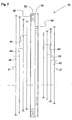
- Fig. 1 shows an elevation 2 of a solar module 4, by means of which the latter is increased at a rear side 6 in order to achieve the best possible exposure to solar radiation can.
- the solar module 4 is held in an inclined position in which an upper side 8 of the solar module 4 relative to the horizontal includes an angle of attack wA between 15 and 45 °.
- the elevation 2 in this case has a wind cover 10, which is attached to the rear side 6.
- the wind cover 10 is a closed sheet metal formed, which functions in addition to its wind-repellent function at the same time as a support means over which the entire occurring at the rear side 6 weight force of the solar module 4 is removed.
- a substantially triangular side cover 12 is also provided, which can be fixed to a sloping side 14 of the elevated solar module 4. In this way, in addition, the visual impression of the elevated solar module 4 can be improved.
- the solar module 4 is connected to a bearing element 18 of the elevation 2.
- Both the wind cover 10 and the bearing element 18 are also connected to a rail construction 20 which rests loosely on a roof 22.
- the wind cover 10 and the bearing member 18 are connected to two rails 24 of the rail structure 20, which extend perpendicular to a longitudinal direction L of the wind cover 10 and the bearing member 18.
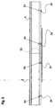
- Fig. 2 shows a solar module assembly 26, which has a plurality of the rail construction 20 sequentially fixed solar modules 4.
- at least two rows of solar modules 4 arranged one behind the other can also be connected to one another laterally, that is to say in the longitudinal direction L of the wind covers 10 and the bearing means 18. Due to the formation of the solar module assembly 26, the individual solar modules 4 are stored rela tively stable even with free edition. In addition, they leave a good visual impression by the straight arrangement both in the longitudinal direction L and in the transverse direction.
- wind covers 10 and the bearing element 18 are connected to both the solar module 4 and the rail structure 20 via screw S1, S2, S3 and S4.
- the wind cover 10 has for this purpose, as in particular Fig. 4 can be seen, a Z-shaped profile with a module-side first end portion 28 and a rail-side second end portion 30, which over a central portion 32 are connected.
- the first end portion 28 and the second end portion 30 are in this case to each other in a mounting angle wM, which corresponds to the intended angle of attack wA substantially.
- the middle section 32 includes a first angle w1 of approximately 90 ° with the first end section 28 and a second angle w2 with the second end section 30, which is approximately 90 ° plus the mounting angle wM.
- module-side fastening means in the form of receiving openings 34 are inserted into the first end section 28, on which connecting screws 36 can be fixed.
- Fig. 5 how out Fig. 5 can be seen, in this case several pairs of receiving openings 34 may be provided, which are each arranged at different distances a1, a2, a3, a4. As a result, different commercially available solar modules 4 can be screwed to the first end section 28, each of which has fastening bores 38 (see FIG Fig. 4 ) with different standard distances.
- the mounting holes 38 and the receiving openings 34 of the first end portion 28 are arranged such that when producing the fferveiexcellent the rear side 6 of the solar module 4 is flush with the central portion 32 of the Z-shaped profile of the wind cover 10.
- Fig. 4 it can also be seen, for the production of the screw S2 between the rail structure 20 and the wind cover 10 in the second end portion 30 rail-side fastening means in the form of slots 40 are inserted, in which hammer head bolts 42 can be fixed.
- the hammer head screws 42 thereby allow a variable fixation of the wind cover 10 along the respective rail 24, wherein a hammer head 44 is displaced through the respective slot 40 into a slot 46 of the rail 24 and is moved by twisting into a position in which it engages behind two edge portions 48 of the rail 24 which delimit the slot 46.
- Fig. 5 also several pairs of slots 40 may be provided, which are each arranged in the different distances a1, a2, a3, a4.
- the screw connections S2 at the same height can be produced at the second end section 30 as the screw connections S1 at the first end section 28.
- the bearing element 18 has a module-side section 50 and a rail-side section 52, which span a bearing angle wL which is substantially 180 ° less the mounting angle wM.
- mounting holes 54 are recessed in the module-side section, where connecting screws 56 can be fixed.
- slots 58 are inserted into the rail-side section 52, where hammer head bolts 60 can be fixed.
- a plurality of pairs of slots 58 are provided, which are each arranged in the different distances a1, a2, a3, a4.
- the screw connections S 4 can be produced at the same height as the screw connections S 1 and S 2 of the wind cover 10.
- each pair of receiving bores 54 may be provided, which are each arranged at different distances b1, b2, b3, b4. This allows the mounting holes 38 (see Fig. 6 ) of different commercial solar modules 4 adjacent to each two of the mounting holes 54 are positioned to produce the screw on this connection S4.
- At least one connecting element 62 may be provided which is bolted to two adjacently arranged screw S4 of the two rows. In this way, the two rows are positively connected to each other via the connecting element 62, as seen from Fig. 8 can be seen.
- ballast elements 64 such as commercial concrete blocks, are attached.
- the wind covers 10 at the bottom second end portions 30 each have an upstanding edge portion 66 which forms a receptacle for the ballast element 64 together with the respective second end portion 30 and the central portion 32.
- the screw connections S2 and S4 are produced directly between the wind cover 10 and the bearing element 18 and the roof 8 without interposition of the rail construction 20.
- the screw S2, S4 can be prepared with the interposition commercial sealant.
- sealing / separating means such as in particular plastic mats or sheets, as corrosion protection and / or sealing material between the elevation 2 and the roof 8 are provided (not shown).
Description
Die Erfindung betrifft ein Aufständersystem für ein Solarmodul, nach dem Oberbegriff des Anspruchs 1, das für eine frei aufliegende Befestigung des Solarmoduls auf einem Dach mit keiner bis geringer Neigung geeignet ist, wie insbesondere auf einem Flachdach. Die Aufständerung weist hierzu Abstützmittel für die Erhöhung einer Seite des Solarmoduls auf, wodurch dieses in einer Schrägstellung positionierbar ist, die eine hohe Aufnahme von Sonnenenergie gewährleistet. An den Anstützmitteln sind dabei modulseitige Befestigungsmittel vorgesehen, die zur Befestigung der Aufständerung an einer Seite des Solarmoduls dienen. Zudem weist die Aufständerung eine Windabdeckung auf, mittels der durch Wind erzeugte Lasten reduziert werden können, die beispielsweise durch am Solarmodul angreifende Auftriebskräfte oder durch zusätzliche Schneelasten in Folge von zwischen dem schräg gestellten Solarmodul und dem betreffenden Dach eingewehten Schnee gebildet sein können. Dabei sind die Abstützmittel durch die Windabdeckung gebildet. Dabei ist die Windabdeckung durch ein Blech gebildet, das ein im Wesentlichen Z-förmiges Profil aufweist. Hierdurch weist die Windabdeckung eine besonders geeignete Form auf, um entlang einer ersten Richtung eine Abdeckfunktion zu übernehmen und gleichzeitig entlang einer quer zur ersten Richtung stehenden zweiten Richtung Gewichtskräfte abtragen zu können. Dabei ist es günstig, wenn das Z-förmige Profil einen ersten Endabschnitt, an dem das Solarmodul befestigbar ist, und einen bodenseitigen zweiten Endabschnitt aufweist.The invention relates to a Aufständersystem for a solar module, according to the preamble of claim 1, which is suitable for a free-lying attachment of the solar module on a roof with no to low inclination, in particular on a flat roof. The elevation has for this purpose supporting means for increasing one side of the solar module, whereby it can be positioned in an inclined position, which ensures a high absorption of solar energy. At the support means while module-side fastening means are provided which serve to attach the elevation on one side of the solar module. In addition, the elevation has a wind cover, by means of which wind-generated loads can be reduced, which may be formed, for example, by buoyancy forces acting on the solar module or by additional snow loads as a result of snow flowing between the tilted solar module and the respective roof. The support means are formed by the wind cover. The wind cover is formed by a metal sheet having a substantially Z-shaped profile. As a result, the wind cover has a particularly suitable shape in order to take over a covering function along a first direction and at the same time to be able to remove weight forces along a second direction transverse to the first direction. It is advantageous if the Z-shaped profile has a first end portion, on which the solar module can be fastened, and a bottom-side second end portion.
Um ein möglichst großes Ertragspotential eines Solarmoduls sicherstellen zu können, muss dieses in einem gewissen Anstellwinkel gegenüber der Horizontalen angeordnet werden. Dieser beträgt beispielsweise in südlichen Teilen Deutschlands bei Südausrichtung etwa 15 bis 45°.In order to ensure the greatest possible yield potential of a solar module, this must be arranged at a certain angle to the horizontal. This is, for example, in southern parts of Germany in southern exposure about 15 to 45 °.
Um auch an Dächern mit einer geringeren Neigung, wie insbesondere an Flachdächern, ein hohes Ertragspotential einer Solaranlage gewährleisten zu können, sind verschiedene Aufständerungssysteme bekannt, mittels denen die betreffenden Solarmodule in einem geeigneten Anstellwinkel gehalten werden können.In order to ensure a high yield potential of a solar system on roofs with a lower inclination, in particular on flat roofs, various Aufständerungssysteme are known, by means of which the relevant solar modules can be kept at a suitable angle.
Eine am Markt erhältliche Aufständerung mit der Bezeichnung "Freiaufstellungs-Montagesystem TRIC F pro" sieht beispielsweise für jedes Solarmodul zwei Stützen vor, die an einem oberen Ende mit dem oberen Rand des betreffenden Solarmoduls und an einem unteren Ende mit einem Schienensystem verbunden sind, das auf dem jeweiligen Flachdach frei aufliegt. Als Windabdeckung dient ein Blech, dass mittels Selbstbohrschrauben an den beiden Stützen befestigt wird. An dem Blech ist ferner eine Art Rinne ausgebildet, die zur Aufnahme von Ballastierungsmitteln in Form von Randsteinen genutzt werden kann.For example, an uplift available on the market called "Freestanding Mounting System TRIC F pro" provides for each solar module two pillars connected at an upper end to the upper edge of the respective solar module and at a lower end to a rail system mounted on rests freely on the respective flat roof. As a wind cover is a sheet that is secured by self-tapping screws on the two supports. On the sheet also a kind of gutter is formed, which can be used to hold ballast agents in the form of curbs.
Die bekannte Aufständerung hat den Vorteil, dass die Solarmodule mit dieser frei aufliegend auf dem jeweiligen Flachdach montiert werden können. Die Standfestigkeit wird dabei allein durch das Eigengewicht der Module, der Aufständerung und gegebenenfalls durch die Ballastierung erreicht, so dass auf Befestigungsmittel verzichtet werden kann, die in das Dach eingelassen werden müssten. Hierdurch kann die Gefahr von Undichtigkeiten, beispielsweise in Folge von Durchdringen einer Dachhaut, vermieden werden.The known elevation has the advantage that the solar modules can be mounted with this freely resting on the respective flat roof. The stability is achieved solely by the weight of the modules, the elevation and optionally by the ballast, so that can be dispensed with fastening means that would have to be embedded in the roof. As a result, the risk of leaks, for example as a result of penetration of a roof skin, can be avoided.
Nachteilig an der bekannten Aufständerung ist, dass diese aus relativ vielen Einzelteilen zusammengesetzt werden muss und dadurch einen relativ hohen Montageaufwand erfordert. Zudem fallen bei der Befestigung der Windabdeckung Metallspäne an, die zu Verunreinigungen und Beschädigungen der Dachhaut führen können.A disadvantage of the known Aufständerung that this must be composed of relatively many items and thus requires a relatively high installation costs. In addition fall when attaching the wind cover metal chips, which can lead to contamination and damage to the roof skin.
Die Aufgabe der Erfindung ist es, bei einer gattungsgemäßen Aufständerung eines Solarmoduls den Montageaufwand weiter zu reduzieren und den optischen Eindruck des aufgeständerten Solarmoduls zu verbessern.The object of the invention is to further reduce the installation effort in a generic elevation of a solar module and to improve the visual impression of the elevated solar module.
Diese Aufgabe wird durch eine Aufständerung mit den Merkmalen des Anspruchs 1 gelöst. Dabei sind an dem zweiten Endabschnitt des Z-förmigen Profils bodenseitige Befestigungsmittel vorgesehen. Dabei ist das Solarmodul an einer von der ersten Seite abgewandten zweiten Seite mit einem Lagerelement verbunden, das einen modulseitigen Abschnitt und einen bodenseitigen Abschnitt aufweist, die einen Lagerwinkel aufspannen, der 180° abzüglich des Montagewinkels beträgt. Hierdurch kann das Solarmodul bezüglich seiner Ausrichtung zur Sonne sowohl an seiner Vorderseite als auch an seiner Rückseite an einem Teil der Aufständerung montiert werden, dessen Ausrichtung dem vorgesehenen Anstellwinkel entspricht. Hierdurch kann der gewünschte Anstellwinkel bei der Montage des Solarmoduls besonders einfach und exakt eingerichtet werden. Zudem sind sowohl der zweite Endabschnitt als auch das Lagerelement hierbei mit einer Schienenkonstruktion verbunden. Hierdurch kann die gleichzeitig als Abstützmittel fungierende Windabdeckung mit weiteren Elementen der Aufständerung verbunden werden, die beispielsweise eine Verbindung zwischen den Windabdeckungen mehrerer Solarmodule erlaubt. Eine solche Schienenkonstruktion ermöglicht dabei die Verbindung der Aufständerungen mehrerer Solarmodule, wodurch eine höhere Standsicherheit erreicht werden kann. Zudem werden die Montage und die Positionierung der einzelnen Solarmodule durch die Verwendung einer derartigen Schienenkonstruktion deutlich vereinfacht. Insbesondere bei Verwendung handelsüblicher Schienen können dabei die Herstellungskosten der Aufständerung relativ gering gehalten werden. Durch diese Ausführung der Abstützmittel beziehungsweise der Windabdeckung wird die Zahl der für die Montage der Aufständerung und des daran im Anstellwinkel gehaltenen Solarmoduls benötigten Bauteile vermindert und der Montageaufwand deutlich reduziert. Zudem kann der optische Eindruck des aufgeständerten Solarmoduls erheblich verbessert werden. Hierbei weist die Schienenkonstruktion vorteilhafterweise zwei Schienen auf, die sich senkrecht zu einer Längserstreckungsrichtung der Windabdeckung erstrecken.This object is achieved by an elevation with the features of claim 1. In this case, bottom-side fastening means are provided at the second end portion of the Z-shaped profile. In this case, the solar module is connected at a side remote from the first side second side with a bearing element having a module-side portion and a bottom-side portion, which span a bearing angle, which is 180 ° minus the mounting angle. As a result, the solar module can be mounted with respect to its orientation to the sun both on its front side and on its rear side on a part of the elevation, whose orientation corresponds to the intended angle of attack. As a result, the desired angle of attack during assembly of the solar module can be set up particularly easily and accurately. In addition, both the second end portion and the bearing element in this case are connected to a rail construction. As a result, the wind cover acting simultaneously as a support means can be connected to other elements of the elevation, which allows, for example, a connection between the wind covers of several solar modules. Such a rail construction allows the connection of the elevations of several solar modules, whereby a higher stability can be achieved. In addition, the installation and positioning of the individual solar modules are significantly simplified by the use of such a rail construction. In particular, when using commercially available rails while the manufacturing cost of the uprising can be kept relatively low. By this embodiment of the support means or the wind cover, the number of components required for mounting the elevation and the solar module held in the angle of attack is reduced and the assembly costs are significantly reduced. In addition, the visual impression of the elevated solar module can be significantly improved. In this case, the rail construction advantageously has two rails which extend perpendicular to a longitudinal direction of the wind cover.
Dabei ist es günstig, wenn der erste Endabschnitt und der zweite Endabschnitt zueinander in einem Montagewinkel angeordnet sind, der an einen vorgesehenen Anstellwinkel für das Solarmodul angepasst ist. Der Montagewinkel kann dabei direkt oder unter Verrechnung einer vorgegebenen Dachschräge mit dem vorgesehenen Anstellwinkel übereinstimmen, der beispielsweise zwischen 15 und 45° beträgt. Hierdurch kann durch die Aufständerung ein geeigneter Anstellwinkel für das zu montierende Solarmodul vorgegeben werden. Auf diese Weise ist bei der Montage der Aufständerung und des daran gehaltenen Solarmoduls keine gesonderte Einstellung des Anstellwinkels nötig.It is advantageous if the first end portion and the second end portion are arranged to each other in a mounting bracket, which is adapted to an intended angle of attack for the solar module. The mounting bracket can match directly or by offsetting a predetermined roof pitch with the intended angle of attack, which is for example between 15 and 45 °. As a result, can be specified by the elevation a suitable angle of attack for the solar module to be mounted. In this way, no separate adjustment of the angle of attack is necessary during assembly of the elevation and the solar module held thereon.
Vorteilhafterweise schließt dabei ein Mittelabschnitt des Z-förmigen Profils mit dem ersten Endabschnitt einen ersten Winkel von etwa 90° und mit dem zweiten Endabschnitt einen zweiten Winkel von etwa 90° zuzüglich des Montagewinkels ein. Auf diese Weise kann das Solarmodul zur Montage relativ stabil an die Aufständerung angelegt und dadurch leichter befestigt werden.Advantageously, a middle section of the Z-shaped profile encloses a first angle of approximately 90 ° with the first end section and a second angle of approximately 90 ° plus the mounting angle with the second end section. In this way, the solar module for mounting relatively stable applied to the elevation and thereby easier to secure.
Dabei ist es besonders günstig, wenn im montierten Zustand des Solarmoduls der Mittelabschnitt des Profils mit einer rückseitigen Stirnfläche der hinteren Seite des am zweiten Endabschnitt montierten Solarmoduls bündig abschließt. Auf diese Weise werden die Angriffsflächen des aufgeständerten Solarmoduls, die von einer Windlast beaufschlagt werden können, minimiert und ein geschlossener optischer Eindruck des Gesamtsystems erzeugt.It is particularly advantageous if in the mounted state of the solar module, the central portion of the profile with a rear end face of the rear side of the solar module mounted on the second end portion is flush. In this way, the attack surfaces of the elevated solar module, which can be acted upon by a wind load, minimized and generates a closed visual impression of the entire system.
Vorteilhafterweise sind die modulseitigen Befestigungsmittel durch Aufnahmeöffnungen gebildet, die in den ersten Endabschnitt des Z-förmigen Profils eingelassen sind. Hierdurch ist eine einfache Befestigung des Solarmoduls an der Auf ständerung über handelsübliche Schraubmittel möglich, insbesondere ohne zusätzliche Modulklemmen.Advantageously, the module-side fastening means are formed by receiving openings, which are embedded in the first end portion of the Z-shaped profile. As a result, a simple attachment of the solar module to the up modification via commercially available screw means, in particular without additional module clamps.
Zudem ist es günstig, wenn die Aufnahmeöffnungen wenigstens zwei Offnungspaare aufweisen, die jeweils in einem Abstand angeordnet sind, der einem Standardabstand zwischen jeweils zwei Befestigungsbohrungen eines handelsüblichen Solarmoduls entspricht. Hierdurch werden mindestens vier Aufnahmeöffnungen bereit gestellt, an denen somit wenigstens zwei unterschiedliche Solarmodule mit gegenseitig unterschiedlich beabstandeten Befestigungsbohrungen verschraubt werden können.In addition, it is favorable if the receiving openings have at least two pairs of openings which are each arranged at a distance which corresponds to a standard spacing between in each case two fastening bores of a commercially available solar module. As a result, at least four receiving openings are provided, on which thus at least two different solar modules can be screwed with mutually differently spaced mounting holes.
In einer weiteren vorteilhaften Ausführungsform weisen die bodenseitigen Befestigungsmittel wenigstens ein Langloch auf, an dem eine Hammerkopfschraube mit der Schienenkonstruktion verbunden ist. Hierdurch ist eine besonders einfache und flexible Befestigung der Windabdeckung an der Schienenkonstruktion möglich.In a further advantageous embodiment, the bottom-side fastening means at least one slot on which a hammer head bolt is connected to the rail construction. As a result, a particularly simple and flexible attachment of the wind cover on the rail construction is possible.
Dabei ist es besonders günstig, wenn sowohl die Aufnahmeöffnungen der Windabdeckung als auch die Aufnahmebohrungen des Lagerelementes direkt an Befestigungsbohrungen anlegbar sind, die an einem handelsüblichen Solarmodul vorgesehen sind. Hierdurch kann die Aufständerung ausschließlich mittels einfacher Schraubverbindungen und insbesondere ohne spezielle Verbindungsmittel, wie beispielsweise Modulklemmen, mit dem Solarmodul verbunden werden.It is particularly advantageous if both the receiving openings of the wind cover and the receiving holes of the bearing element can be applied directly to mounting holes, which are provided on a commercial solar module. As a result, the elevation can be connected to the solar module exclusively by means of simple screw connections and in particular without special connection means, such as module clamps.
Vorteilhafterweise ist an einer sich quer zur ersten Seite erstreckenden Schrägseite des Solarmoduls eine im Wesentlichen dreieckige Seitenabdeckung vorgesehen. Hierdurch ist an wenigstens einer Schrägseite des aufgeständerten Solarmoduls beziehungsweise eines Solarmodulverbundes auch eine seitliche Windabweisung herstellbar, wodurch die durch Wind erzeugbaren Auftriebslasten an dem Solarmodul beziehungsweise dem Solarmodulverbund deutlich reduziert werden können. Zudem verleiht eine derartige Seitenabdeckung dem betreffenden Solarmodul beziehungsweise dem Solarmodulverbund eine geschlossene Form, durch die sich der optische Eindruck der Anlage deutlich verbessern lässt, insbesondere wenn an beiden beziehungsweise allen Schrägseiten des Solarmoduls beziehungsweise des Solarmodulverbundes gleichartige Seitenabdeckungen vorgesehen sind.Advantageously, a substantially triangular side cover is provided on a diagonal side of the solar module extending transversely to the first side. As a result, a lateral wind deflection can be produced on at least one inclined side of the elevated solar module or of a solar module assembly, as a result of which the buoyancy loads that can be generated by wind on the solar module or the solar module assembly can be significantly reduced. In addition, such a side cover gives the relevant solar module or the solar module assembly a closed shape, by which the visual impression of the system can be significantly improved, especially if similar side covers are provided on both or all oblique sides of the solar module or the solar module group.
Zudem ist es günstig, wenn an der Windabdeckung eine Aufnahme für ein Ballastelement vorgesehen ist, wodurch das Eigengewicht der Aufständerung bedarfsweise erhöht werden kann, um eine ausreichende Standsicherheit zu gewährleisten.In addition, it is advantageous if a receptacle for a ballast element is provided on the wind cover, whereby the weight of the Aufständerung can be increased if necessary, in order to ensure sufficient stability.
Dabei ist es günstig, wenn die Aufnahme durch einen am bodenseitigen Endabschnitt vorgesehenen nach oben stehenden Randabschnitt begrenzt ist, der sich einstückig an das Z-förmige Profil der Windabdeckung anschließt. Hierdurch kann die Windabdeckung neben ihrer eigentlichen Abdeckfunktion und der zusätzlichen Abstützfunktion des Weiteren auch als Ballastaufnahme fungieren. Durch diese Vereinigung von drei Funktionen an einem Bauteil weist die Aufständerung eine minimale Anzahl von Einzelelementen auf, was wiederum einen minimalen Montageaufwand zur Folge hat.It is advantageous if the recording is limited by a provided on the bottom end portion upstanding edge portion which integrally connects to the Z-shaped profile of the wind cover. As a result, in addition to its actual covering function and the additional supporting function, the wind cover can also act as a ballast receptacle. This combination of three functions on a component, the elevation has a minimum number of individual elements, which in turn has a minimal installation effort result.
In den Figuren ist eine beispielhafte Ausführungsform der Erfindung dargestellt. Es zeigen:
- Figur 1
- eine perspektivische Ansicht eines Solarmoduls mit einer erfindungsgemäßen Aufständerung,
Figur 2- eine Draufsicht auf einen Solarmodulverbund aus mehreren Solarmodulen gemäß
Fig. 1 , Figur 3- eine Seitenansicht der Aufständerung in Richtung III aus
Fig. 1 , Figur 4- einen Schnitt durch eine Windabdeckung der Aufständerung nach
Fig. 3 in der Ebene einer Verschraubung, - Figur 5
- eine Draufsicht auf die Windabdeckung in Richtung V aus
Fig. 4 in vereinzelter Darstellung, Figur 6- einen Schnitt durch ein Lagerelement der Aufständerung nach
Fig. 3 in der Ebene einer Verschraubung, Figur 7- eine Draufsicht auf das Lagerelement in Richtung VII aus
Fig. 6 in vereinzelter Darstellung, - Figur 8
- eine Ansicht zweier nebeneinander liegender und seitlich miteinander verbundener Solarmodule und
- Figur 9
- eine Ansicht eines Solarmoduls bei direkter Festlegung der Aufständerung an einem Dach
- FIG. 1
- a perspective view of a solar module with an elevation invention,
- FIG. 2
- a plan view of a solar module assembly of several solar modules according to
Fig. 1 . - FIG. 3
- a side view of the elevation in the direction of III
Fig. 1 . - FIG. 4
- a section through a wind cover of the upstand after
Fig. 3 in the plane of a screw connection, - FIG. 5
- a plan view of the wind cover in the direction of V out
Fig. 4 in isolated presentation, - FIG. 6
- a section through a bearing element of the elevation after
Fig. 3 in the plane of a screw connection, - FIG. 7
- a plan view of the bearing element in the direction VII
Fig. 6 in isolated presentation, - FIG. 8
- a view of two side by side and laterally interconnected solar modules and
- FIG. 9
- a view of a solar module with direct fixing of the elevation on a roof
Die Aufständerung 2 weist dabei eine Windabdeckung 10 auf, die an der hinteren Seite 6 befestigt ist. Die Windabdeckung 10 ist dabei als geschlossenes Blech ausgebildet, das neben seiner Wind abweisenden Funktion gleichzeitig als Abstützmittel fungiert, über das die gesamte an der hinteren Seite 6 auftretende Gewichtskraft des Solarmoduls 4 abgetragen wird.The
Zur seitlichen Windabweisung ist zudem eine im Wesentlichen dreieckige Seitenabdeckung 12 vorgesehen, die an einer Schrägseite 14 des aufgeständerten Solarmoduls 4 festlegbar ist. Hierdurch kann zudem der optische Eindruck des aufgeständerten Solarmoduls 4 verbessert werden.For lateral wind deflection, a substantially
An einer von der hinteren Seite 6 abgewandten vorderen Seite 16 ist das Solarmodul 4 mit einem Lagerelement 18 der Aufständerung 2 verbunden. Sowohl die Windabdeckung 10 als auch das Lagerelement 18 sind zudem mit einer Schienenkonstruktion 20 verbunden, die lose auf einem Dach 22 aufliegt. Dabei sind die Windabdeckung 10 und das Lagerelement 18 mit zwei Schienen 24 der Schienenkonstruktion 20 verbunden, die sich senkrecht zu einer Längserstreckungsrichtung L der Windabdeckung 10 und des Lagerelements 18 erstrecken.At a
Wie aus
Die Windabdeckung 10 weist hierzu, wie insbesondere aus
Der Mittelabschnitt 32 schließt dabei mit dem ersten Endabschnitt 28 einen ersten Winkel w1 von etwa 90° und mit dem zweiten Endabschnitt 30 einen zweiten Winkel w2 ein, der etwa 90° zuzüglich des Montagewinkels wM beträgt.The
Zur Herstellung der Schraubverbindung S1 zwischen dem Solarmodul 4 und der Windabdeckung 10, sind in den ersten Endabschnitt 28 modulseitige Befestigungsmittel in Form von Aufnahmeöffnungen 34 eingelassen, an denen Verbindungsschrauben 36 festlegbar sind.To produce the screw connection S1 between the
Wie aus
Die Befestigungsbohrungen 38 und die Aufnahmeöffnungen 34 des ersten Endabschnittes 28 sind dabei derart angeordnet, dass bei Herstellung der Schraubveibindung die hintere Seite 6 des Solarmoduls 4 bündig mit dem Mittelabschnitt 32 des Z-förmigen Profils der Windabdeckung 10 abschließt.The mounting holes 38 and the receiving
Wie aus
Wie aus
Wie aus
Wie insbesondere aus
Zudem können auch mehrere Paare von Aufnahmebohrungen 54 vorgesehen werden, die jeweils in unterschiedlichen Abständen b1, b2, b3, b4 angeordnet sind. Hierdurch können die Befestigungsbohrungen 38 (siehe
Zur stabilen seitlichen Verbindung zwischen zwei nebeneinander verlegten Reihen von Solarmodulen 4 kann zudem wenigstens ein Verbindungselement 62 vorgesehen werden, das jeweils an zwei benachbart angeordneten Schraubverbindungen S4 der beiden Reihen mit verschraubt ist. Auf diese Weise werden die beiden Reihen über das Verbindungselement 62 formschlüssig miteinander verbunden, wie aus
Um die Standfestigkeit des frei aufliegenden Solarmodulverbundes 26 insgesamt zu erhöhen, können an den Windabdeckungen 10, wie aus
Alternativ zu der frei aufliegenden Montage des Solarmoduls 4 beziehungsweise des Solarmodulverbundes 26 ist es alternativ auch möglich, das wenigstens eine aufgeständerte Solarmodul 4 beziehungsweise zumindest Teile des aufgeständerten Solarmodulverbundes 26 direkt an dem Dach 22 festzuschrauben, wie in
Zudem können unabhängig davon, ob eine Schienenkonstruktion verwendet wird oder nicht, handelsübliche Dicht-/Trennmittel, wie insbesondere Kunststoffmatten oder -Bahnen, als Korrosionsschutz und/oder Dichtmaterial zwischen der Aufständerung 2 und dem Dach 8 vorgesehen werden (nicht dargestellt).In addition, regardless of whether a rail construction is used or not, commercially available sealing / separating means, such as in particular plastic mats or sheets, as corrosion protection and / or sealing material between the
Claims (12)
- Support (2) for a solar module (4) for free-standing securing on a roof (22), with no or little inclination,
with support means for the raising of a first side (6) of the solar module (4) in relation to a second side (16) of the solar module (4), facing away from the first side (6), in an oblique position,
wherein, at the support means, module-side securing means are provided for securing to the first side (6) of solar module (4), and the solar module (4) is connected on the second side (16) to a bearing element (18),
and with a wind cover (10), by means of which the loads incurred by the influence of the wind can be reduced, wherein the support means are formed by the wind cover (10), and the wind cover (10) is formed by a sheet configured with a Z-shaped profile, which comprises a first end section (28), to which the solar module (4) can be secured, and a base-side second end section (30),
wherein, base-side securing means are provided at the second end section (30) of the Z-shaped profile,
characterized in that the bearing element (18) on the second side (16) comprises a module-side section (50) and a base-side section (52), which span a bearing angle (mL) which amounts to 180° less the mounting angle (mw),
wherein both the second end section (30) as well as the bearing element (18) are connected to a rail construction (20). - Support according to claim 1, characterized in that the rail construction (20) comprises two rails (24), which extend perpendicular to a longitudinal extension direction (L) of the wind cover (10).
- Support according to claim 1 or 2, characterized in that the first end section (28) and the second end section (30) are arranged in relation to one another at an installation angle (mW) which is adjusted to a predetermined setting angle (mA) for the solar module (4).
- Support according to any one of claims 1 to 3, characterized in that a middle section (32) of the Z-shaped profile with the first end section (28) encloses a first angle (w1) of some 90°, and with the second end section (30) encloses a second angle (w2) of some 90° plus the installation angle (wM).
- Support according to claim 4, characterized in that the middle section (32) of the Z-shaped profile connects flush with the first side (6) of the solar module (4) mounted at the second end section (30).
- Support according to any one of claims 1 to 5, characterized in that the module-side securing means are formed by accommodation openings (34), which are let into the first end section (28) of the Z-shaped profile
- Support according to claim 6, characterized in that the accommodation openings (34) comprise at least two opening pairs, which in each case are arranged at a distance (a1; a2; s3; a4), which in each case corresponds to a standard distance interval between two securing holes (38) of a commercially conventional solar module (4).
- Support according to any one of claims 1 to 7, characterized in that the base-side securing means comprise at least one longitudinal hole (40), at which at least one hammerhead screw (42) can be connected with the rail construction (20).
- Support according to any one of claims 1 to 8, characterized in that both the accommodation openings (34) of the wind cover (10) as well as the accommodation holes (54) of the bearing element (18) can be laid directly at securing holes (38) of the solar module (4).
- Support according to any one of claims 1 to 9, characterized in that, on an oblique side (14) of the solar module (4) extending transverse to the first side (6), an essentially triangular side cover (12) is provided.
- Support according to any one of claims 1 to 10, characterized in that a mount for a ballast element (64) is provided at the wind cover (10)
- Support according to claim 11, characterized in that the mount is delimited by a upward standing edge section (66) provided at the base-side end section (30).
Applications Claiming Priority (1)
| Application Number | Priority Date | Filing Date | Title |
|---|---|---|---|
| DE102010024660A DE102010024660A1 (en) | 2010-06-22 | 2010-06-22 | Erecting a solar module |
Publications (3)
| Publication Number | Publication Date |
|---|---|
| EP2400238A2 EP2400238A2 (en) | 2011-12-28 |
| EP2400238A3 EP2400238A3 (en) | 2013-01-23 |
| EP2400238B1 true EP2400238B1 (en) | 2016-03-02 |
Family
ID=44800351
Family Applications (1)
| Application Number | Title | Priority Date | Filing Date |
|---|---|---|---|
| EP11002863.6A Not-in-force EP2400238B1 (en) | 2010-06-22 | 2011-04-06 | Support for a solar module |
Country Status (2)
| Country | Link |
|---|---|
| EP (1) | EP2400238B1 (en) |
| DE (1) | DE102010024660A1 (en) |
Families Citing this family (3)
| Publication number | Priority date | Publication date | Assignee | Title |
|---|---|---|---|---|
| DE202012005673U1 (en) | 2012-06-12 | 2012-07-09 | Stefan Weber | Connecting arrangement of a solar module |
| US9742347B2 (en) * | 2013-02-11 | 2017-08-22 | Jonathan Port | Modular strap mount for solar panels |
| DE202023002677U1 (en) | 2023-12-22 | 2024-02-12 | Markus Rensburg | Kit for mounting solar modules |
Family Cites Families (9)
| Publication number | Priority date | Publication date | Assignee | Title |
|---|---|---|---|---|
| JPH1122126A (en) * | 1997-07-02 | 1999-01-26 | Sanko Metal Ind Co Ltd | Solar roof board and solar roof |
| DE20120983U1 (en) * | 2001-12-27 | 2002-04-18 | Schoenau Ag | Modulhalter |
| NL1020947C1 (en) * | 2002-06-27 | 2003-12-30 | Stroomwerk Energy B V | A frame. |
| JP5116238B2 (en) * | 2006-02-07 | 2013-01-09 | 旭化成ホームズ株式会社 | Solar panel fixing structure |
| DE202006009678U1 (en) * | 2006-06-21 | 2006-09-07 | Zimmerei Schwörer GmbH | Support structure with solar modules for generating current from sunlight has support for lower-lying edge or solar modules, which is of angular profile whereby higher support profile is approximately of Z or U-shaped crossection |
| DE102008035345A1 (en) * | 2008-07-29 | 2010-02-04 | Soltech ökologische Techniken Handels GmbH | Fastening unit for supporting structure for solar module, has base plate, which is provided on structure, where base plate of carrier course is made from non-decomposed, ultraviolet resistant plastic |
| DE202009016269U1 (en) * | 2009-12-01 | 2010-03-04 | Naundorf Gmbh | Support element for fixing solar modules |
| DE202010001083U1 (en) * | 2010-01-19 | 2010-03-25 | Hafenbahn Gmbh & Co. Kg | Device for arranging solar panels and / or heat collectors on a substrate |
| DE202010002455U1 (en) * | 2010-02-17 | 2010-05-06 | Wörsching Ingenieure GmbH | Aufständerung for solar modules |
-
2010
- 2010-06-22 DE DE102010024660A patent/DE102010024660A1/en not_active Ceased
-
2011
- 2011-04-06 EP EP11002863.6A patent/EP2400238B1/en not_active Not-in-force
Also Published As
| Publication number | Publication date |
|---|---|
| EP2400238A2 (en) | 2011-12-28 |
| EP2400238A3 (en) | 2013-01-23 |
| DE102010024660A1 (en) | 2011-12-22 |
Similar Documents
| Publication | Publication Date | Title |
|---|---|---|
| EP2270402B1 (en) | Combination of trough collector and mounting bracket | |
| EP2771913B1 (en) | Retaining system for installing a photovoltaic module | |
| EP2388539A2 (en) | Assembly base for solar modules and assembly system with multiple such assembly bases | |
| DE202009018534U1 (en) | mounting system | |
| DE202009003124U1 (en) | Support for substructure of solar modules and substructure of solar modules | |
| WO2012095195A2 (en) | Mounting system for a solar system, and solar system having the mounting system | |
| EP2402679A2 (en) | Mounting device for assembling solar modules | |
| DE102013207827A1 (en) | Device for fixing solar modules and roof | |
| DE202020104397U1 (en) | Photovoltaic system | |
| DE102009054242A1 (en) | Device for fastening at least one solar module | |
| EP1845319B1 (en) | Attachment unit for mounting auxiliary roof elements on a sloping roof | |
| DE102008050529A1 (en) | Photovoltaic system, photovoltaic module, substructure and method for equipping a photovoltaic system | |
| EP2400238B1 (en) | Support for a solar module | |
| DE102014106800B4 (en) | Stand arrangement for a solar panel | |
| DE102021124625A1 (en) | Photovoltaic mounting system | |
| DE102013216173A1 (en) | Arrangement and method for holding at least one photovoltaic module | |
| EP2554925B1 (en) | Support element for a solar module | |
| WO2014029500A2 (en) | Roof substructure in zigzag form | |
| WO2014020006A1 (en) | Fastening element for mounting solar modules or solar collectors on a roof, and pitched roof having a fastening element | |
| DE202010017971U1 (en) | Device for supporting solar modules | |
| EP2246646A2 (en) | Roof hook | |
| DE102009037978B4 (en) | Shoring for a photovoltaic open-space plant and method for mounting a shoring | |
| EP2388537A2 (en) | Assembly base for solar modules and assembly system with multiple such assembly bases | |
| DE202012000203U1 (en) | Supporting construction for flat modules, in particular for solar modules | |
| DE102010029004A1 (en) | Mounting foot for solar modules and mounting system with several such mounting feet |
Legal Events
| Date | Code | Title | Description |
|---|---|---|---|
| AK | Designated contracting states |
Kind code of ref document: A2 Designated state(s): AL AT BE BG CH CY CZ DE DK EE ES FI FR GB GR HR HU IE IS IT LI LT LU LV MC MK MT NL NO PL PT RO RS SE SI SK SM TR |
|
| AX | Request for extension of the european patent |
Extension state: BA ME |
|
| PUAI | Public reference made under article 153(3) epc to a published international application that has entered the european phase |
Free format text: ORIGINAL CODE: 0009012 |
|
| PUAL | Search report despatched |
Free format text: ORIGINAL CODE: 0009013 |
|
| AK | Designated contracting states |
Kind code of ref document: A3 Designated state(s): AL AT BE BG CH CY CZ DE DK EE ES FI FR GB GR HR HU IE IS IT LI LT LU LV MC MK MT NL NO PL PT RO RS SE SI SK SM TR |
|
| AX | Request for extension of the european patent |
Extension state: BA ME |
|
| RIC1 | Information provided on ipc code assigned before grant |
Ipc: F24J 2/52 20060101AFI20121214BHEP Ipc: F24J 2/22 20060101ALI20121214BHEP |
|
| 17P | Request for examination filed |
Effective date: 20130723 |
|
| RBV | Designated contracting states (corrected) |
Designated state(s): AL AT BE BG CH CY CZ DE DK EE ES FI FR GB GR HR HU IE IS IT LI LT LU LV MC MK MT NL NO PL PT RO RS SE SI SK SM TR |
|
| 17Q | First examination report despatched |
Effective date: 20150120 |
|
| GRAP | Despatch of communication of intention to grant a patent |
Free format text: ORIGINAL CODE: EPIDOSNIGR1 |
|
| INTG | Intention to grant announced |
Effective date: 20151008 |
|
| GRAS | Grant fee paid |
Free format text: ORIGINAL CODE: EPIDOSNIGR3 |
|
| GRAA | (expected) grant |
Free format text: ORIGINAL CODE: 0009210 |
|
| AK | Designated contracting states |
Kind code of ref document: B1 Designated state(s): AL AT BE BG CH CY CZ DE DK EE ES FI FR GB GR HR HU IE IS IT LI LT LU LV MC MK MT NL NO PL PT RO RS SE SI SK SM TR |
|
| REG | Reference to a national code |
Ref country code: GB Ref legal event code: FG4D Free format text: NOT ENGLISH |
|
| REG | Reference to a national code |
Ref country code: AT Ref legal event code: REF Ref document number: 778325 Country of ref document: AT Kind code of ref document: T Effective date: 20160315 Ref country code: CH Ref legal event code: EP |
|
| REG | Reference to a national code |
Ref country code: IE Ref legal event code: FG4D Free format text: LANGUAGE OF EP DOCUMENT: GERMAN |
|
| REG | Reference to a national code |
Ref country code: DE Ref legal event code: R096 Ref document number: 502011008945 Country of ref document: DE |
|
| REG | Reference to a national code |
Ref country code: NL Ref legal event code: MP Effective date: 20160302 |
|
| REG | Reference to a national code |
Ref country code: LT Ref legal event code: MG4D |
|
| PG25 | Lapsed in a contracting state [announced via postgrant information from national office to epo] |
Ref country code: HR Free format text: LAPSE BECAUSE OF FAILURE TO SUBMIT A TRANSLATION OF THE DESCRIPTION OR TO PAY THE FEE WITHIN THE PRESCRIBED TIME-LIMIT Effective date: 20160302 Ref country code: GR Free format text: LAPSE BECAUSE OF FAILURE TO SUBMIT A TRANSLATION OF THE DESCRIPTION OR TO PAY THE FEE WITHIN THE PRESCRIBED TIME-LIMIT Effective date: 20160603 Ref country code: FI Free format text: LAPSE BECAUSE OF FAILURE TO SUBMIT A TRANSLATION OF THE DESCRIPTION OR TO PAY THE FEE WITHIN THE PRESCRIBED TIME-LIMIT Effective date: 20160302 Ref country code: NO Free format text: LAPSE BECAUSE OF FAILURE TO SUBMIT A TRANSLATION OF THE DESCRIPTION OR TO PAY THE FEE WITHIN THE PRESCRIBED TIME-LIMIT Effective date: 20160602 Ref country code: ES Free format text: LAPSE BECAUSE OF FAILURE TO SUBMIT A TRANSLATION OF THE DESCRIPTION OR TO PAY THE FEE WITHIN THE PRESCRIBED TIME-LIMIT Effective date: 20160302 |
|
| PG25 | Lapsed in a contracting state [announced via postgrant information from national office to epo] |
Ref country code: LV Free format text: LAPSE BECAUSE OF FAILURE TO SUBMIT A TRANSLATION OF THE DESCRIPTION OR TO PAY THE FEE WITHIN THE PRESCRIBED TIME-LIMIT Effective date: 20160302 Ref country code: LT Free format text: LAPSE BECAUSE OF FAILURE TO SUBMIT A TRANSLATION OF THE DESCRIPTION OR TO PAY THE FEE WITHIN THE PRESCRIBED TIME-LIMIT Effective date: 20160302 Ref country code: SE Free format text: LAPSE BECAUSE OF FAILURE TO SUBMIT A TRANSLATION OF THE DESCRIPTION OR TO PAY THE FEE WITHIN THE PRESCRIBED TIME-LIMIT Effective date: 20160302 Ref country code: RS Free format text: LAPSE BECAUSE OF FAILURE TO SUBMIT A TRANSLATION OF THE DESCRIPTION OR TO PAY THE FEE WITHIN THE PRESCRIBED TIME-LIMIT Effective date: 20160302 Ref country code: PL Free format text: LAPSE BECAUSE OF FAILURE TO SUBMIT A TRANSLATION OF THE DESCRIPTION OR TO PAY THE FEE WITHIN THE PRESCRIBED TIME-LIMIT Effective date: 20160302 Ref country code: NL Free format text: LAPSE BECAUSE OF FAILURE TO SUBMIT A TRANSLATION OF THE DESCRIPTION OR TO PAY THE FEE WITHIN THE PRESCRIBED TIME-LIMIT Effective date: 20160302 Ref country code: BE Free format text: LAPSE BECAUSE OF NON-PAYMENT OF DUE FEES Effective date: 20160430 |
|
| PG25 | Lapsed in a contracting state [announced via postgrant information from national office to epo] |
Ref country code: EE Free format text: LAPSE BECAUSE OF FAILURE TO SUBMIT A TRANSLATION OF THE DESCRIPTION OR TO PAY THE FEE WITHIN THE PRESCRIBED TIME-LIMIT Effective date: 20160302 Ref country code: IS Free format text: LAPSE BECAUSE OF FAILURE TO SUBMIT A TRANSLATION OF THE DESCRIPTION OR TO PAY THE FEE WITHIN THE PRESCRIBED TIME-LIMIT Effective date: 20160702 |
|
| PG25 | Lapsed in a contracting state [announced via postgrant information from national office to epo] |
Ref country code: SK Free format text: LAPSE BECAUSE OF FAILURE TO SUBMIT A TRANSLATION OF THE DESCRIPTION OR TO PAY THE FEE WITHIN THE PRESCRIBED TIME-LIMIT Effective date: 20160302 Ref country code: RO Free format text: LAPSE BECAUSE OF FAILURE TO SUBMIT A TRANSLATION OF THE DESCRIPTION OR TO PAY THE FEE WITHIN THE PRESCRIBED TIME-LIMIT Effective date: 20160302 Ref country code: SM Free format text: LAPSE BECAUSE OF FAILURE TO SUBMIT A TRANSLATION OF THE DESCRIPTION OR TO PAY THE FEE WITHIN THE PRESCRIBED TIME-LIMIT Effective date: 20160302 Ref country code: PT Free format text: LAPSE BECAUSE OF FAILURE TO SUBMIT A TRANSLATION OF THE DESCRIPTION OR TO PAY THE FEE WITHIN THE PRESCRIBED TIME-LIMIT Effective date: 20160704 Ref country code: CZ Free format text: LAPSE BECAUSE OF FAILURE TO SUBMIT A TRANSLATION OF THE DESCRIPTION OR TO PAY THE FEE WITHIN THE PRESCRIBED TIME-LIMIT Effective date: 20160302 |
|
| REG | Reference to a national code |
Ref country code: CH Ref legal event code: PL |
|
| REG | Reference to a national code |
Ref country code: DE Ref legal event code: R097 Ref document number: 502011008945 Country of ref document: DE |
|
| PG25 | Lapsed in a contracting state [announced via postgrant information from national office to epo] |
Ref country code: IT Free format text: LAPSE BECAUSE OF FAILURE TO SUBMIT A TRANSLATION OF THE DESCRIPTION OR TO PAY THE FEE WITHIN THE PRESCRIBED TIME-LIMIT Effective date: 20160302 |
|
| PLBE | No opposition filed within time limit |
Free format text: ORIGINAL CODE: 0009261 |
|
| STAA | Information on the status of an ep patent application or granted ep patent |
Free format text: STATUS: NO OPPOSITION FILED WITHIN TIME LIMIT |
|
| REG | Reference to a national code |
Ref country code: IE Ref legal event code: MM4A |
|
| REG | Reference to a national code |
Ref country code: FR Ref legal event code: ST Effective date: 20161230 |
|
| PG25 | Lapsed in a contracting state [announced via postgrant information from national office to epo] |
Ref country code: CH Free format text: LAPSE BECAUSE OF NON-PAYMENT OF DUE FEES Effective date: 20160430 Ref country code: LI Free format text: LAPSE BECAUSE OF NON-PAYMENT OF DUE FEES Effective date: 20160430 Ref country code: FR Free format text: LAPSE BECAUSE OF NON-PAYMENT OF DUE FEES Effective date: 20160502 Ref country code: DK Free format text: LAPSE BECAUSE OF FAILURE TO SUBMIT A TRANSLATION OF THE DESCRIPTION OR TO PAY THE FEE WITHIN THE PRESCRIBED TIME-LIMIT Effective date: 20160302 |
|
| 26N | No opposition filed |
Effective date: 20161205 |
|
| PG25 | Lapsed in a contracting state [announced via postgrant information from national office to epo] |
Ref country code: BG Free format text: LAPSE BECAUSE OF FAILURE TO SUBMIT A TRANSLATION OF THE DESCRIPTION OR TO PAY THE FEE WITHIN THE PRESCRIBED TIME-LIMIT Effective date: 20160602 Ref country code: SI Free format text: LAPSE BECAUSE OF FAILURE TO SUBMIT A TRANSLATION OF THE DESCRIPTION OR TO PAY THE FEE WITHIN THE PRESCRIBED TIME-LIMIT Effective date: 20160302 |
|
| GBPC | Gb: european patent ceased through non-payment of renewal fee |
Effective date: 20160602 |
|
| PG25 | Lapsed in a contracting state [announced via postgrant information from national office to epo] |
Ref country code: IE Free format text: LAPSE BECAUSE OF NON-PAYMENT OF DUE FEES Effective date: 20160406 Ref country code: GB Free format text: LAPSE BECAUSE OF NON-PAYMENT OF DUE FEES Effective date: 20160602 |
|
| REG | Reference to a national code |
Ref country code: AT Ref legal event code: MM01 Ref document number: 778325 Country of ref document: AT Kind code of ref document: T Effective date: 20160406 |
|
| PG25 | Lapsed in a contracting state [announced via postgrant information from national office to epo] |
Ref country code: AT Free format text: LAPSE BECAUSE OF NON-PAYMENT OF DUE FEES Effective date: 20160406 |
|
| REG | Reference to a national code |
Ref country code: DE Ref legal event code: R079 Ref document number: 502011008945 Country of ref document: DE Free format text: PREVIOUS MAIN CLASS: F24J0002520000 Ipc: F24S0025000000 |
|
| REG | Reference to a national code |
Ref country code: DE Ref legal event code: R082 Ref document number: 502011008945 Country of ref document: DE Representative=s name: WACKER, JOST, DIPL.-ING., DE |
|
| PG25 | Lapsed in a contracting state [announced via postgrant information from national office to epo] |
Ref country code: CY Free format text: LAPSE BECAUSE OF FAILURE TO SUBMIT A TRANSLATION OF THE DESCRIPTION OR TO PAY THE FEE WITHIN THE PRESCRIBED TIME-LIMIT Effective date: 20160302 Ref country code: HU Free format text: LAPSE BECAUSE OF FAILURE TO SUBMIT A TRANSLATION OF THE DESCRIPTION OR TO PAY THE FEE WITHIN THE PRESCRIBED TIME-LIMIT; INVALID AB INITIO Effective date: 20110406 |
|
| PG25 | Lapsed in a contracting state [announced via postgrant information from national office to epo] |
Ref country code: TR Free format text: LAPSE BECAUSE OF FAILURE TO SUBMIT A TRANSLATION OF THE DESCRIPTION OR TO PAY THE FEE WITHIN THE PRESCRIBED TIME-LIMIT Effective date: 20160302 Ref country code: MK Free format text: LAPSE BECAUSE OF FAILURE TO SUBMIT A TRANSLATION OF THE DESCRIPTION OR TO PAY THE FEE WITHIN THE PRESCRIBED TIME-LIMIT Effective date: 20160302 Ref country code: LU Free format text: LAPSE BECAUSE OF NON-PAYMENT OF DUE FEES Effective date: 20160406 Ref country code: MC Free format text: LAPSE BECAUSE OF FAILURE TO SUBMIT A TRANSLATION OF THE DESCRIPTION OR TO PAY THE FEE WITHIN THE PRESCRIBED TIME-LIMIT Effective date: 20160302 Ref country code: MT Free format text: LAPSE BECAUSE OF FAILURE TO SUBMIT A TRANSLATION OF THE DESCRIPTION OR TO PAY THE FEE WITHIN THE PRESCRIBED TIME-LIMIT Effective date: 20160302 |
|
| PGFP | Annual fee paid to national office [announced via postgrant information from national office to epo] |
Ref country code: DE Payment date: 20180313 Year of fee payment: 8 |
|
| PG25 | Lapsed in a contracting state [announced via postgrant information from national office to epo] |
Ref country code: AL Free format text: LAPSE BECAUSE OF FAILURE TO SUBMIT A TRANSLATION OF THE DESCRIPTION OR TO PAY THE FEE WITHIN THE PRESCRIBED TIME-LIMIT Effective date: 20160302 |
|
| REG | Reference to a national code |
Ref country code: DE Ref legal event code: R119 Ref document number: 502011008945 Country of ref document: DE |
|
| PG25 | Lapsed in a contracting state [announced via postgrant information from national office to epo] |
Ref country code: DE Free format text: LAPSE BECAUSE OF NON-PAYMENT OF DUE FEES Effective date: 20191101 |