EP2400050A2 - Apparatus for determining status of weft insertion and weft insertion controller in jet loom - Google Patents
Apparatus for determining status of weft insertion and weft insertion controller in jet loom Download PDFInfo
- Publication number
- EP2400050A2 EP2400050A2 EP11170844A EP11170844A EP2400050A2 EP 2400050 A2 EP2400050 A2 EP 2400050A2 EP 11170844 A EP11170844 A EP 11170844A EP 11170844 A EP11170844 A EP 11170844A EP 2400050 A2 EP2400050 A2 EP 2400050A2
- Authority
- EP
- European Patent Office
- Prior art keywords
- weft
- angles
- converted
- arrival
- detected
- Prior art date
- Legal status (The legal status is an assumption and is not a legal conclusion. Google has not performed a legal analysis and makes no representation as to the accuracy of the status listed.)
- Granted
Links
- 238000003780 insertion Methods 0.000 title claims abstract description 81
- 230000037431 insertion Effects 0.000 title claims abstract description 81
- 238000009941 weaving Methods 0.000 claims abstract description 57
- 238000002347 injection Methods 0.000 claims abstract description 35
- 239000007924 injection Substances 0.000 claims abstract description 35
- 238000001514 detection method Methods 0.000 claims abstract description 14
- 239000012530 fluid Substances 0.000 claims abstract description 6
- 230000005415 magnetization Effects 0.000 description 12
- 238000006243 chemical reaction Methods 0.000 description 11
- 230000005347 demagnetization Effects 0.000 description 11
- 238000004804 winding Methods 0.000 description 9
- 238000005259 measurement Methods 0.000 description 7
- 230000005856 abnormality Effects 0.000 description 5
- 238000005070 sampling Methods 0.000 description 5
- 238000000034 method Methods 0.000 description 4
- 230000002411 adverse Effects 0.000 description 1
- 230000003068 static effect Effects 0.000 description 1
- 239000002759 woven fabric Substances 0.000 description 1
Images


Classifications
-
- D—TEXTILES; PAPER
- D03—WEAVING
- D03D—WOVEN FABRICS; METHODS OF WEAVING; LOOMS
- D03D47/00—Looms in which bulk supply of weft does not pass through shed, e.g. shuttleless looms, gripper shuttle looms, dummy shuttle looms
- D03D47/28—Looms in which bulk supply of weft does not pass through shed, e.g. shuttleless looms, gripper shuttle looms, dummy shuttle looms wherein the weft itself is projected into the shed
- D03D47/30—Looms in which bulk supply of weft does not pass through shed, e.g. shuttleless looms, gripper shuttle looms, dummy shuttle looms wherein the weft itself is projected into the shed by gas jet
- D03D47/3093—Displaying data
-
- D—TEXTILES; PAPER
- D03—WEAVING
- D03D—WOVEN FABRICS; METHODS OF WEAVING; LOOMS
- D03D47/00—Looms in which bulk supply of weft does not pass through shed, e.g. shuttleless looms, gripper shuttle looms, dummy shuttle looms
- D03D47/28—Looms in which bulk supply of weft does not pass through shed, e.g. shuttleless looms, gripper shuttle looms, dummy shuttle looms wherein the weft itself is projected into the shed
- D03D47/30—Looms in which bulk supply of weft does not pass through shed, e.g. shuttleless looms, gripper shuttle looms, dummy shuttle looms wherein the weft itself is projected into the shed by gas jet
- D03D47/3026—Air supply systems
- D03D47/3033—Controlling the air supply
- D03D47/304—Controlling of the air supply to the auxiliary nozzles
-
- D—TEXTILES; PAPER
- D03—WEAVING
- D03D—WOVEN FABRICS; METHODS OF WEAVING; LOOMS
- D03D51/00—Driving, starting, or stopping arrangements; Automatic stop motions
- D03D51/18—Automatic stop motions
- D03D51/34—Weft stop motions
Definitions
- the present invention relates to an apparatus for determining status of weft insertion and a weft insertion controller in a jet loom.
- Wefts are inserted from main nozzles for weft insertion with air injection.
- the timing for a weft to reach the end of weft insertion changes with each weft insertion. If this arrival time greatly differs from target timing for the weft, failure of weft insertion or reduced quality of woven fabric occurs.
- dobby and jacquard there is a large fluctuation in load on opened warps, and the rotational speed of a weaving machine changes greatly depending on such fluctuation in load.
- the arrival time for a weft is greatly offset from the target time.
- conditions for weft insertion are predetermined in a manner to delay the arrival time of the weft compared to the standard when the load on opened warps is large and to accelerate the arrival time of the weft compared to the standard when the load on the opened warps is small.
- the arrival time of the weft is detected for each weft insertion in each pattern of the opened warps, and the condition for weft insertion is corrected with the difference between the detected value and a target value so that the condition corresponds to a pattern at the next time or later.
- Japanese Laid-Open Patent Publication 2010-65331 discloses a method for displaying the status of weft insertion in which information regarding factors that vary fly of wefts and information regarding statistic values pertaining to the arrival time of wefts is displayed on the same screen.
- the former information regarding factors that vary fly of wefts includes information concerning switching of a yarn feeder, operation for resetting the condition for weft insertion, density of wefts, and a pattern for openings defined by warps and rotational speed of a weaving machine.
- the latter information regarding statistic values includes standard deviations. When abnormality in a statistic value is identified, it can be determined if the information displayed together with the statistic value is responsible for such an abnormality.
- arrival time of a weft is displayed with a rotation angle for a weaving machine based on the information detected by a rotation angle detecting means of a weaving machine. That is, the rotation angle of a weaving machine when the weft has reached the end of weft insertion is used as the arrival time for the weft.
- the detected arrival time of a weft represented by the rotation angle of the weaving machine greatly deviates from target arrival time even when the actual flying period of the weft does not differ so much from a target flying period. Due to the great difference between the detected value and the target value of the arrival time, the condition for weft insertion to correspond to the pattern at the next time or later is corrected. This may cause adverse fluctuation in actual flying period of the weft and cause great change in the detected arrival time.
- the rotation angle of a weaving machine when arrival of a weft is detected is also used as the weft arrival time in the method of JP2010-65331A for displaying statistic values (standard deviations). Accordingly, in the weaving method where the fluctuation in the load on the openings defined by warps is large, i.e., the fluctuation in the rotational speed of a weaving machine is large, such as double weaving, the arrival time of the weft represented by the rotation angle of a weaving machine is greatly changed in spite of the fact that the actual flying period of the weft is not offset from the target flying period. As a result, the statistic value (standard deviation) becomes great. This makes it difficult to determine the magnitude of the variation in the arrival times of wefts. As long as the rotation angle of a weaving machine when the arrival of the weft is detected is used as the weft arrival time, the magnitude of the variation in the arrival times of wefts cannot be determined appropriately.
- An object of the invention is to determine the magnitude of the variation in the arrival times of wefts appropriately.
- apparatus for determining status of weft insertion in a jet loom including weft arrival detection means (25) for detecting a weft inserted by injection of fluid.
- the apparatus comprises clock means (K) for measuring a weft flying period (t1 (s)) from the start time of insertion of a weft to the arrival time of the weft; and converting means (Co) for converting the weft flying period (t1 (s)) into a weft flying angle (t1 (t)) at standard rotational speed (R) of a weaving machine using the weft flying period (t1 (s)) measured by the clock means and the standard rotational speed (R).
- the apparatus further comprises statistic means (Co) for calculating a converted weft arrival angle (Tw(t)) using the weft flying angle (t1 (t)) and creating statistic data of converted angles based on the converted weft arrival angle (Tw(t)); and display control means (34) for displaying the statistic data of converted angles created by the statistic means (Co).
- statistic means Co for calculating a converted weft arrival angle (Tw(t)) using the weft flying angle (t1 (t)) and creating statistic data of converted angles based on the converted weft arrival angle (Tw(t)
- display control means (34) for displaying the statistic data of converted angles created by the statistic means (Co).
- the statistic data of converted angles include standard deviations ( ⁇ ) of converted angles calculated from the converted weft arrival angle Tw(t).
- the apparatus further comprises rotation angle detection means (32) for detecting a rotation angle of the weaving machine, wherein the statistic means (Co) creates statistic data of detected angles detected by the rotation angle detection means (32).
- the statistic data of detected angles include standard deviations ( ⁇ ) of detected angles calculated from the detected weft arrival angles (Tw( ⁇ )).
- the display control means (34) switches between a first screen (G1, G5) displaying the statistic data of converted angles and a second screen (G2, G6) displaying the statistic data of detected angles.
- the statistic data of converted angles is a histogram (H1) of the converted weft arrival angles (Tw(t)).
- the statistic data of detected angles is a histogram (H2) of the detected weft arrival angles (Tw( ⁇ )).
- a weft insertion controller in a jet loom in which a weft is ejected by air injection of a main nozzle (15A, 15B) for weft insertion and guided by air injection by an auxiliary nozzle (16, 17, 18, 19) for weft insertion.
- the weft insertion controller comprises pressure adjustment means (C, 35, 36) for adjusting air pressure supplied to the main nozzle (15A, 15B); control means (Co, C1) for controlling a adjustment status of the pressure adjustment means (C, 35, 36); and the above apparatus for determining a status of weft insertion.
- the control means (Co, C1) controls the adjustment status of the pressure adjustment means (C, 35, 36) using the converted weft arrival angle (t1 (t)) calculated by the converting means (Co).
- a weft insertion controller in a jet loom in which a weft is ejected by air injection of a main nozzle (15A, 15B) for weft insertion and guided by air injection by an auxiliary nozzle (16, 17, 18, 19) for weft insertion is provided.
- the weft insertion controller comprises injection timing adjustment means (C1, 21, 22, 23, 24) for adjusting injection timing in the auxiliary nozzle (16, 17, 18, 19); control means (Co, C1) for controlling an adjustment status of the injection timing adjustment means (C1, 21, 22, 23, 24); and the above apparatus for determining a status of weft insertion.
- the control means (Co, C1) controls the adjustment status of the injection timing adjustment means (C1, 21, 22, 23, 24) using the converted weft arrival angle (t1 (t)) calculated by the converting means (Co).
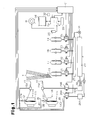
- a drive motor M for driving a weaving machine as illustrated in Fig. 1 is under the control of a main control computer Co.
- Numerals 11A and 11 B denote winding-type weft-length-measurement storage apparatus. Winding of a weft Y1 over a thread winding face 111 of the weft-length-measurement storage apparatus 11A and removal and release of the weft Y1 from the thread winding face 111 of the weft-length-measurement storage apparatus 11A are controlled by advancement and retraction of an engaging pin 121.
- Winding of a weft Y2 over a thread winding face 111 of the weft-length-measurement storage apparatus 11 B and removal and release of the weft Y2 from the weft-length-measurement storage apparatus 11 B are controlled by advancement and retraction of another engage pin 121.
- electromagnetic solenoids 12A and 12B When electromagnetic solenoids 12A and 12B are demagnetized, the engaging pins 121 protrude to prevent the wefts Y1 and Y2 from being removed and released from the corresponding thread winding faces 111.
- the electromagnetic solenoids 12A and 12B are magnetized, the engaging pins 121 retract to allow the wefts Y1 and Y2 to be removed and released from the corresponding thread winding faces 111.
- An auxiliary computer C1 is connected to the main control computer Co to communicate signals.
- the main control computer Co and the auxiliary computer C1 communicate various kinds of information.
- the electromagnetic solenoids 12A and 12B are magnetized or demagnetized under the control of the auxiliary computer C1.
- the auxiliary computer C1 controls magnetization and demagnetization of the electromagnetic solenoid 12A based on the information on weft release detection from a weft release detector 14A, and controls magnetization and demagnetization of the electromagnetic solenoid 12B based on the information on weft release detection from a weft release detector 14B.
- the weft Y1 is drawn from the thread winding face 111 of the weft-length-measurement storage apparatus 11A by the injection action of air (fluid) at a main nozzle 15A for weft insertion and ejected into an opening defined by warps T.
- the weft Y1 ejected from the main nozzle 15A is injected in a relayed manner with a set of auxiliary nozzles 16, 17, 18 and 19 for weft insertion.
- the weft Y2 is drawn from the thread winding face 111 of the weft-length-measurement storage apparatus 11 B by the injection action of air (fluid) at a main nozzle 15B for weft insertion and ejected into the openings defined by the warps T.
- the weft Y2 ejected from the main nozzle 15B is injected in a relayed manner with the set of auxiliary nozzles 16, 17, 18 and 19.
- the presence or absence of arrival of the wefts Y1 and Y2 at the end of weft insertion is detected by a weft arrival detector 25 within the scope of a predetermined rotation angle of a weaving machine.
- the weft arrival detector 25 is a means for detecting weft arrival, and may be a photoelectric sensor.
- the information regarding the presence or absence of weft arrival detected by the weft arrival detector 25 is transmitted to the main control computer Co. When arrival is absent, the main control computer Co stops the operation of the weaving machine based on the input signal of absence of arrival.
- Air injection at the main nozzle 15A is controlled by magnetization and demagnetization of an electromagnetic valve 20A.
- Air injection at the main nozzle 15B is controlled by magnetization and demagnetization of an electromagnetic valve 20B.
- Respective pressurized air injections for weft insertion at the auxiliary nozzles 16, 17, 18 and 19 are controlled by magnetization and demagnetization of electromagnetic valves 21, 22, 23 and 24.
- the electromagnetic valve 20A is connected to a pressurized-air supply tank 26A.
- the electromagnetic valve 20B is connected to a pressurized-air supply tank 26B.
- the electromagnetic valves 21, 22, 23 and 24 are connected to a pressurized-air supply tank 27.
- the pressurized-air supply tank 26A is connected to a source pressure tank 29 via a pressure adjustment valve 28.
- the pressurized-air supply tank 26B is connected to the source pressure tank 29 via a pressure adjustment valve 30.
- the pressurized-air supply tank 27 is connected to the source pressure tank 29 via a pressure adjustment valve 31.
- Each electromagnetic valve 20A, 20B, 21, 22, 23 and 24 is magnetized or demagnetized under the control of the auxiliary computer C1.
- the auxiliary computer C1 directs magnetization or demagnetization of each electromagnetic valve 20A, 20B, 21, 22, 23 and 24 based on the information regarding the rotation angle of a weaving machine detected by and sent from a rotary encoder 32.
- the rotary encoder 32 serves as rotation angle detection means for detecting the rotation angle of a weaving machine.
- An input device 33 is connected to the main control computer Co to communicate signals.
- Information such as rotational speed of the weaving machine, type of wefts, density of the wefts, weaving conditions (e.g., weaving width), and pressure is input from the input device 33 to the main control computer Co to be set in the main control computer Co.
- the main control computer Co determines timing for magnetizing or demagnetizing each of the electromagnetic solenoids 12A and 12B and the electromagnetic valves 20A, 20B, 21, 22, 23 and 24 for each type of wefts based on the input information for weaving. Then, in weaving, the main control computer Co magnetizes or demagnetizes each of the electromagnetic solenoids 12A and 12B and the electromagnetic valves 20A, 20B, 21, 22, 23 and 24 on the determined timing for magnetization or demagnetization.
- a display device 34 is connected to the main control computer Co to communicate signals.
- a display on the display device 34 is controlled by the main control computer Co.
- the display device 34 and the main control computer Co constitute display control means.
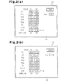
- Figs. 2(a) and (b) illustrate screens on the display device 34.
- the main control computer Co includes controls to switch screens between the first screen G1 illustrated in Fig. 2(a) and the second screen G2 illustrated in Fig. 2(b) based on the operation of the input device 33.
- the main control computer Co also includes controls to change the numerical data in the square boxes in the screens G1 and G2 based on the information on the rotation angle of a weaving machine obtained from the rotary encoder 32, the information on detection of weft release obtained from the weft release detector 14A and 14B and the information on presence of weft arrival by the weft arrival detector 25.
- the symbol Y1 on each of the screens G1 and G2 represents the weft Y1 that is inserted.
- the symbol Y2 on each of the screens G1 and G2 represents the weft Y2 that is inserted.
- a column of square boxes under the symbol Y1 is the column representing numeric values pertaining to the weft Y1 and a column of square boxes under the symbol Y1 is the column representing numeric values pertaining to the weft Y2.
- the symbol Tp denotes start time of weft insertion of the wefts Y1 and Y2.
- the symbol Tbw denotes termination time of weft insertion of the weft Y1 and Y2.
- the start time of weft insertion is the sum of the start time of magnetization of the electromagnetic solenoid 12A and 12B and the delay time associated with retraction of the corresponding engagement pin 121.
- the termination time of weft insertion is the sum of the start time of demagnetization of the electromagnetic solenoid 12A and 12B and the delay time associated with protrusion of the corresponding engagement pin 121.
- Tb1, Tb2 and Tb3 denote detection times of 1 st , 2 nd , and 3 rd weft release obtained from the weft release detector 14A and 14B.
- the symbol SAMPLING denotes the number or times of sampling for the start time of weft insertion, the detection time for weft release, the termination time for weft insertion, the arrival time of the weft, the rotational speed of the weaving machine, and the converted arrival time of the weft, in a plurality of weft insertions.
- the number of sampling is 30 times for weft insertions.
- the number "30" next to the symbol "SAMPLING" represents the number for sampling.
- the symbol Rpm denotes rotational speed of a weaving machine.
- the number in the square box on the right side of the symbol Rpm represents the rate of rotation (or rotational speed) in the weaving machine.
- a target rotation rate number (or target number of rotations) R is input by the operation of the input device 33.
- the main control computer Co displays this input target rotation rate number R on the display device 34.
- the symbol STD denotes standard deviation of angles of weft arrival.
- the symbol TIME on the upper right side of the first screen G1 means that the first screen G1 is a screen that displays the timing after each conversion by the main control computer Co.
- the symbol ANGLE on the upper right side of the second screen G2 means that the second screen G2 is a screen that displays the timing before each conversion by the main control computer Co.
- the main control computer Co changes numeric values in the square boxes on the first screen G1 for every 30 weft insertions.
- the main control computer Co changes numeric values in the square boxed on the second screen G2 for every 30 insertions.
- the main control computer Co specifies the start time of weft insertion as a start angle Tp ( ⁇ ) of weft insertion, in the format of a rotation angle of a weaving machine, based on the information on the start time of magnetization of the electromagnetic solenoids 12A, 12B and information on the rotation angle of a weaving machine obtained from the rotary encoder 32. That is, the start time of weft insertion is specified as the start angle Tp( ⁇ ), which is the rotation angle of a weaving machine corresponding to the sum of the start time of magnetization of the electromagnetic solenoids 12A, 12B and the delay time.
- the main control computer Co specifies the arrival time of a weft detected by the weft arrival detector 25 as a detected weft arrival angle Tw( ⁇ ), in the format of a rotation angle of a weaving machine, based on the information on presence of weft arrival obtained from the weft arrival detector 25 and the information on the rotation angle of a weaving machine obtained from the rotary encoder 32. That is, the arrival time of a weft is specified as the detected weft arrival angle Tw( ⁇ ), which is the rotation angle of a weaving machine at the time when the weft arrival detector 25 detects it.
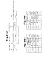
- the table of Fig. 3(b) is a table of data indicating changes in weft insertion start angle Tp( ⁇ ), the number of rotation of a weaving machine, and the detected weft arrival angle ( ⁇ ) after starting the operation of the weaving machine.
- the main control computer Co includes clock means K (illustrated in Fig. 1 ).
- the main control computer Co measures a weft flying period t1 (s) with the clock means K.
- the weft flying period t1 (s) is the time period between the start time of weft insertion and the arrival time of the weft.
- the numeric value "1004" on the right side of the symbol Rpm on the first screen G1 of Fig. 2(a) is an example of the target rotation rate number R.
- t1(t) is the conversion of the weft flying period t1(s) into the weft flying angle at the target rotational number R. That is, the main control computer Co converts the weft flying period t1(s) into the weft flying angle t1(t) at the standard rotational speed, using the weft flying period t1(s) (the period from the start of weft insertion to the weft arrival) and standard rotational speed (target rotational number R).
- the main control computer Co serves as converting means for converting the weft flying period t1(s) into the weft flying angle t1(t) at the standard rotational speed using the weft flying period t1(s) measured by the clock means K and the standard rotational speed.
- Tw(t) is an angle converted from the weft arrival period into the weft arrival angle at the target rotation rate number R. That is, the main control computer Co converts the weft arrival period into the converted weft arrival angle Tw(t) at standard rotational speed using the weft flying period t1(s) from the start of weft insertion to the weft arrival and the standard rotational speed (target rotation rate number R) of the weaving machine.
- the table of Fig. 3(c) is a table of data indicating changes in the converted weft insertion start angle Tp(t), the target rotation rate number R (standard rotation rate number), the converted weft arrival angle Tw(t) after starting the operation of the weaving machine.
- the starting point of the weft flying period t1(s) is Tp( ⁇ ).
- Tp( ⁇ ) is equal to Tp(t).
- the main control computer Co creates histogram information as statistic data of converted angles using the converted weft arrival angle Tw(t) and instructs the display device 34 to display the histogram H1 (statistic data of converted angles) as illustrated in Fig. 4(a) .
- the axis of abscissas represents weft arrival angle and the axis of ordinate represents frequency. Numeric values on the axis of abscissas means standard values of weft arrival angle in the range of ⁇ 2. 5.
- the main control computer Co creates histogram information as statistic data of detected angles using the detected weft arrival angle Tw( ⁇ ) detected by the rotary encoder 32, and instructs the display device 34 to display the histogram H2 (static data of detected angles) as illustrated in Fig. 4(b) .
- the axis of abscissas represents weft arrival angle and the axis of ordinate represents frequency. Numeric values on the axis of abscissas means standard values of weft arrival angle in the range of ⁇ 2.5.
- the main control computer Co serves as a statistic means for creating the statistic data for converted angles and the statistic data for detected angles.
- the histograms H1 and H2 on the screens G3 and G4 of Figs. 4(a) and (b) relate to the weft arrival angles for the same weft insertions of 100 picks.
- the histograms H1 and H2 of Figs. 4(a) and (b) show an example of double weaving, where the load on the opening defined by warps is large, i.e., the fluctuation in rotational speed of the weaving machine is great.
- the frequency distribution using the detected weft arrival angle Tw( ⁇ ) detected by the rotary encoder 32 (the histogram H2) has two peaks. According to the histogram H2, it may be speculated that the variation in the weft flying periods t1 (s) is great. However, the frequency distribution using the converted weft arrival angle Tw(t) has one peak. According to the histogram H1, it is understood that the variation in the weft flying periods t1(s) is small.
- the main control computer Co calculates standard deviation ⁇ of the converted angles (statistic data of converted angles) using the converted weft arrival angle Tw(t).
- ⁇ is 1.5 in the weft Y1 and ⁇ is 1.8 in the weft Y2.
- the main control computer Co calculates standard deviation ⁇ of the detected angles (statistic data of detected angles) using the detected weft arrival angle Tw( ⁇ ) detected by the rotary encoder 32.
- ⁇ is 8.9 in the weft Y1 and ⁇ is 9.8 in the weft Y2.
- the standard deviation ⁇ of detected angles using the detected weft arrival angle Tw( ⁇ ) detected by the rotary encoder 32 is large. Thus, according to the standard deviation ⁇ of detected angles, it may be speculated that the variations in weft flying periods t1(s) is great. However, the standard deviation ⁇ of the converted angles using the converted weft arrival angle Tw(t) is small. Thus, according to the standard deviation ⁇ of the converted angles, it is understood that the variation in the weft flying periods t1 (s) is small.
- the main control computer Co, the auxiliary computer C1 and the display device 34 constitute an apparatus for determining status of weft insertion that converts the weft flying period t1 (s) into the weft flying angle t1 (t) at the standard rotational speed.
- the first embodiment has the following advantages.
- Each electric pressure adjustment valve 35, 36 and 37 illustrated in Fig. 5 is a pressure adjustment valve equipped with a motor.
- An auxiliary computer C1 controls the rotational position of the motor of each electric pressure adjustment valve 35, 36 and 37 to control the status for pressure adjustment of the electric pressure adjustment valve 35, 36 and 37. That is, each electric pressure adjustment valve 35, 36 and 37 is pressure controlled by the auxiliary computer C1 so that the pressure of each pressurized-air supply tank 26A, 26B and 27 is adjusted in accordance with the status of the electric pressure adjustment valve 35, 36, 37.
- Pressure detectors 38, 39, 40 and 41 are connected to the auxiliary computer C1 to communicate signals.
- the pressure detectors 38, 39, 40 and 41 detect the pressures in the source pressure tanks 29, 27, 26A and 26B, respectively.
- the auxiliary computer C1 performs feedback control for adjusting each of the pressures in the tanks 29, 27, 26A and 26B to the target pressure based on the information on the pressure detected by each of the pressure detectors 38, 39, 40 and 41.
- the auxiliary computer C1 also controls injection pressure at the main nozzles 15A and 15B by adjusting the pressures in the tanks 26A and 26B using the converted weft arrival angle Tw(t).
- This injection pressure control is a control for adjusting the arrival time of a weft to approach the target arrival time for that weft.
- the auxiliary computer C1 and the electric pressure adjustment valves 35 and 36 constitute pressure adjustment means for adjusting air pressure supplied to the main nozzles 15A and 15B.
- the main control computer Co and the auxiliary computer C1 constitute control means for controlling the adjustment status of the pressure adjustment means.
- the auxiliary computer C1 also controls injection timings at the auxiliary nozzles 16, 17, 18 and 19 by adjusting the timings of magnetization and demagnetization at the electromagnetic valves 21, 22, 23 and 24 using the converted weft arrival angle Tw(t).
- This injection timing control is a control of reducing the variation in the arrival times of wefts.
- the auxiliary computer C1 and the electromagnetic valve 21, 22, 23 and 24 constitute injection timing adjustment means for adjusting the injection timings at the auxiliary nozzles 16, 17, 18 and 19.
- the main control computer Co and the auxiliary computer C1 constitute control means for controlling the adjustment status of the injection timing adjustment means.
- a first screen G5 illustrated in Fig. 6 displays a histogram H1 and a second screen G6 illustrated in Fig. 7 displays a histogram H2.
- the main control computer Co serves to instruct the display device 34 to display the histograms H1 and H2 together with standard deviations.
- the first screen G5 and the second screen G6 may be switched by the operation of the input device 33.
- the symbol "System Pressure” indicated in Fig. 6 and 7 means the pressure in the source pressure tank 29.
- the numeric value in the square box on the right side of the symbol “System Pressure” is an example of the pressure value in the source pressure tank 29.
- the main control computer Co instructs to change the displayed value in the square box on the right side of the symbol “System Pressure” based on the information on the pressure detected by the pressure detector 38.
- the symbol “Main pressure” denotes the pressures in the tanks 26A and 26B.
- the numeric value in the square box on the right side of the symbol “Main pressure” is an example of the pressure value in the tank 26A.
- the numeric value in the square box on the right side of that square box is an example of the pressure value in the tank 26B.
- the main control computer Co instructs to change the displayed values in the two square boxes based on the information on the pressures detected by the pressure detectors 40 and 41.
- the converted weft arrival angle Tw(t) is used to adjust the injection pressure in the main nozzles 15A and 15B.
- control of weft flying to approach the arrival time of a weft to the target arrival time of a weft with high accuracy is achieved.
- the converted weft arrival angle Tw(t) is used to adjust the injection timings at the auxiliary nozzles 16, 17, 18 and 19.
- control of weft flying to reduce the variation in arrival times of wefts is achieved.
- the present invention may be also embodied in the following embodiments.
- Contents displayed on the first screen G1 in Fig. 2(a) and contents displayed on the second screen G2 in Fig. 2(b) may be displayed on the same screen.
- Contents displayed on the first screen G5 in Fig. 6 and contents displayed on the second screen G6 in Fig. 7 may be displayed on the same screen.
- the start time for weft insertion may be set to the same as the time to start magnetization of the electromagnetic solenoids 12A and 12B.
- the termination time for weft insertion may be set to the same as the time to start demagnetization of the electromagnetic solenoids 12A and 12B.
- an average value of the rotational speeds of the weaving machine at the predetermined pick number for welt insertion may be used. This average value may be input by the operation of the input device 33, or the main control computer Co may set the average value to the standard rotational speed after starting the operation of the weaving machine.
- Rotation of the drive motor M of the weaving machine is conducted to a main shaft of the weaving machine via a motor pulley.
- rotational speed in the weaving machine can be changed.
- standard rotational speed may be input by the operation of the input device 33.
- Apparatus for determining status of weft insertion in a jet loom including weft arrival detection means (25) for detecting a weft inserted by injection of fluid is provided.
- the apparatus comprises clock means (K) for measuring a weft flying period (t1(s)) from the start time of insertion of a weft to the arrival time of the weft; and converting means (Co) for converting the weft flying period (t1 (s)) into a weft flying angle (t1 (t)) at standard rotational speed (R) of a weaving machine using the weft flying period (t1 (s)) measured by the clock means and the standard rotational speed (R).
Landscapes
- Engineering & Computer Science (AREA)
- Textile Engineering (AREA)
- Looms (AREA)
Abstract
Description
- The present invention relates to an apparatus for determining status of weft insertion and a weft insertion controller in a jet loom.
- Wefts are inserted from main nozzles for weft insertion with air injection. The timing for a weft to reach the end of weft insertion changes with each weft insertion. If this arrival time greatly differs from target timing for the weft, failure of weft insertion or reduced quality of woven fabric occurs. In dobby and jacquard, there is a large fluctuation in load on opened warps, and the rotational speed of a weaving machine changes greatly depending on such fluctuation in load. When the rotational speed of a weaving machine changes greatly, the arrival time for a weft is greatly offset from the target time.
- In a weft insertion controller disclosed in Japanese Laid-Open Patent Publication No.
9-250053 - Japanese Laid-Open Patent Publication
2010-65331 - Generally, arrival time of a weft is displayed with a rotation angle for a weaving machine based on the information detected by a rotation angle detecting means of a weaving machine. That is, the rotation angle of a weaving machine when the weft has reached the end of weft insertion is used as the arrival time for the weft.
- Therefore, in the apparatus of
JP9-250053A - The rotation angle of a weaving machine when arrival of a weft is detected is also used as the weft arrival time in the method of
JP2010-65331A - An object of the invention is to determine the magnitude of the variation in the arrival times of wefts appropriately.
- According to one aspect of the invention, apparatus for determining status of weft insertion in a jet loom including weft arrival detection means (25) for detecting a weft inserted by injection of fluid is provided. The apparatus comprises clock means (K) for measuring a weft flying period (t1 (s)) from the start time of insertion of a weft to the arrival time of the weft; and converting means (Co) for converting the weft flying period (t1 (s)) into a weft flying angle (t1 (t)) at standard rotational speed (R) of a weaving machine using the weft flying period (t1 (s)) measured by the clock means and the standard rotational speed (R).
- In one embodiment, the apparatus further comprises statistic means (Co) for calculating a converted weft arrival angle (Tw(t)) using the weft flying angle (t1 (t)) and creating statistic data of converted angles based on the converted weft arrival angle (Tw(t)); and display control means (34) for displaying the statistic data of converted angles created by the statistic means (Co).
- In another embodiment, the statistic data of converted angles include standard deviations (α) of converted angles calculated from the converted weft arrival angle Tw(t).
- In another embodiment, the apparatus further comprises rotation angle detection means (32) for detecting a rotation angle of the weaving machine, wherein the statistic means (Co) creates statistic data of detected angles detected by the rotation angle detection means (32).
- In another embodiment, the statistic data of detected angles include standard deviations (β) of detected angles calculated from the detected weft arrival angles (Tw(θ)).
- In another embodiment, the display control means (34) switches between a first screen (G1, G5) displaying the statistic data of converted angles and a second screen (G2, G6) displaying the statistic data of detected angles.
- In another embodiment, the statistic data of converted angles is a histogram (H1) of the converted weft arrival angles (Tw(t)).
- In another embodiment, the statistic data of detected angles is a histogram (H2) of the detected weft arrival angles (Tw(θ)).
- In another aspect of the invention, a weft insertion controller in a jet loom in which a weft is ejected by air injection of a main nozzle (15A, 15B) for weft insertion and guided by air injection by an auxiliary nozzle (16, 17, 18, 19) for weft insertion is provided. The weft insertion controller comprises pressure adjustment means (C, 35, 36) for adjusting air pressure supplied to the main nozzle (15A, 15B); control means (Co, C1) for controlling a adjustment status of the pressure adjustment means (C, 35, 36); and the above apparatus for determining a status of weft insertion. The control means (Co, C1) controls the adjustment status of the pressure adjustment means (C, 35, 36) using the converted weft arrival angle (t1 (t)) calculated by the converting means (Co).
- In yet another aspect of the invention, a weft insertion controller in a jet loom in which a weft is ejected by air injection of a main nozzle (15A, 15B) for weft insertion and guided by air injection by an auxiliary nozzle (16, 17, 18, 19) for weft insertion is provided. The weft insertion controller comprises injection timing adjustment means (C1, 21, 22, 23, 24) for adjusting injection timing in the auxiliary nozzle (16, 17, 18, 19); control means (Co, C1) for controlling an adjustment status of the injection timing adjustment means (C1, 21, 22, 23, 24); and the above apparatus for determining a status of weft insertion. The control means (Co, C1) controls the adjustment status of the injection timing adjustment means (C1, 21, 22, 23, 24) using the converted weft arrival angle (t1 (t)) calculated by the converting means (Co).
-
-
Fig. 1 is a schematic view illustrating a weft insertion apparatus according to a first embodiment; -
Fig. 2(a) is a view of a screen that displays converted weft arrival angles and standard deviations of the converted angles; -
Fig. 2 (b) is a view of a screen that displays weft arrival angles and standard deviations of the detected angles before the conversion (determined based on the detected information of the rotation angle of a weaving machine); -
Fig. 3(a) illustrates the process of conversion; -
Fig. 3(b) illustrates a table showing data of arrival angles of wefts before conversion; -
Fig. 3(c) illustrates a table showing data of converted arrival angles of wefts after conversion; -
Fig. 4(a) is a histogram of arrival angles of wefts after conversion; -
Fig. 4(b) is a histogram of arrival angles of wefts before conversion; -
Fig. 5 is a schematic view illustrating a weft insertion apparatus according to a second embodiment; -
Fig. 6 is a view of a screen that displays a histogram after conversion; and -
Fig. 7 is a view of a screen that displays a histogram before conversion. - An air jet loom for 2-color weft insertion according to a first embodiment of the invention will be described with reference to
Figs. 1 to 4 . - A drive motor M for driving a weaving machine as illustrated in
Fig. 1 is under the control of a main control computer Co.Numerals thread winding face 111 of the weft-length-measurement storage apparatus 11A and removal and release of the weft Y1 from thethread winding face 111 of the weft-length-measurement storage apparatus 11A are controlled by advancement and retraction of anengaging pin 121. Winding of a weft Y2 over athread winding face 111 of the weft-length-measurement storage apparatus 11 B and removal and release of the weft Y2 from the weft-length-measurement storage apparatus 11 B are controlled by advancement and retraction of another engagepin 121. Whenelectromagnetic solenoids engaging pins 121 protrude to prevent the wefts Y1 and Y2 from being removed and released from the correspondingthread winding faces 111. When theelectromagnetic solenoids engaging pins 121 retract to allow the wefts Y1 and Y2 to be removed and released from the correspondingthread winding faces 111. - An auxiliary computer C1 is connected to the main control computer Co to communicate signals. The main control computer Co and the auxiliary computer C1 communicate various kinds of information. The
electromagnetic solenoids electromagnetic solenoid 12A based on the information on weft release detection from aweft release detector 14A, and controls magnetization and demagnetization of theelectromagnetic solenoid 12B based on the information on weft release detection from aweft release detector 14B. - The weft Y1 is drawn from the
thread winding face 111 of the weft-length-measurement storage apparatus 11A by the injection action of air (fluid) at amain nozzle 15A for weft insertion and ejected into an opening defined by warps T. The weft Y1 ejected from themain nozzle 15A is injected in a relayed manner with a set ofauxiliary nozzles thread winding face 111 of the weft-length-measurement storage apparatus 11 B by the injection action of air (fluid) at amain nozzle 15B for weft insertion and ejected into the openings defined by the warps T. The weft Y2 ejected from themain nozzle 15B is injected in a relayed manner with the set ofauxiliary nozzles - The presence or absence of arrival of the wefts Y1 and Y2 at the end of weft insertion is detected by a
weft arrival detector 25 within the scope of a predetermined rotation angle of a weaving machine. Theweft arrival detector 25 is a means for detecting weft arrival, and may be a photoelectric sensor. The information regarding the presence or absence of weft arrival detected by theweft arrival detector 25 is transmitted to the main control computer Co. When arrival is absent, the main control computer Co stops the operation of the weaving machine based on the input signal of absence of arrival. - Air injection at the
main nozzle 15A is controlled by magnetization and demagnetization of anelectromagnetic valve 20A. Air injection at themain nozzle 15B is controlled by magnetization and demagnetization of anelectromagnetic valve 20B. Respective pressurized air injections for weft insertion at theauxiliary nozzles electromagnetic valves electromagnetic valve 20A is connected to a pressurized-air supply tank 26A. Theelectromagnetic valve 20B is connected to a pressurized-air supply tank 26B. Theelectromagnetic valves air supply tank 27. - The pressurized-
air supply tank 26A is connected to asource pressure tank 29 via a pressure adjustment valve 28. The pressurized-air supply tank 26B is connected to thesource pressure tank 29 via apressure adjustment valve 30. The pressurized-air supply tank 27 is connected to thesource pressure tank 29 via apressure adjustment valve 31. - Each
electromagnetic valve electromagnetic valve rotary encoder 32. Therotary encoder 32 serves as rotation angle detection means for detecting the rotation angle of a weaving machine. - An
input device 33 is connected to the main control computer Co to communicate signals. Information such as rotational speed of the weaving machine, type of wefts, density of the wefts, weaving conditions (e.g., weaving width), and pressure is input from theinput device 33 to the main control computer Co to be set in the main control computer Co. The main control computer Co determines timing for magnetizing or demagnetizing each of theelectromagnetic solenoids electromagnetic valves electromagnetic solenoids electromagnetic valves - A
display device 34 is connected to the main control computer Co to communicate signals. A display on thedisplay device 34 is controlled by the main control computer Co. Thedisplay device 34 and the main control computer Co constitute display control means. -
Figs. 2(a) and (b) illustrate screens on thedisplay device 34. The main control computer Co includes controls to switch screens between the first screen G1 illustrated inFig. 2(a) and the second screen G2 illustrated inFig. 2(b) based on the operation of theinput device 33. The main control computer Co also includes controls to change the numerical data in the square boxes in the screens G1 and G2 based on the information on the rotation angle of a weaving machine obtained from therotary encoder 32, the information on detection of weft release obtained from theweft release detector weft arrival detector 25. - The symbol Y1 on each of the screens G1 and G2 represents the weft Y1 that is inserted. The symbol Y2 on each of the screens G1 and G2 represents the weft Y2 that is inserted. A column of square boxes under the symbol Y1 is the column representing numeric values pertaining to the weft Y1 and a column of square boxes under the symbol Y1 is the column representing numeric values pertaining to the weft Y2.
- The symbol Tp denotes start time of weft insertion of the wefts Y1 and Y2. The symbol Tbw denotes termination time of weft insertion of the weft Y1 and Y2. The start time of weft insertion is the sum of the start time of magnetization of the
electromagnetic solenoid corresponding engagement pin 121. The termination time of weft insertion is the sum of the start time of demagnetization of theelectromagnetic solenoid corresponding engagement pin 121. - The symbols Tb1, Tb2 and Tb3 denote detection times of 1st, 2nd, and 3rd weft release obtained from the
weft release detector - The symbol SAMPLING denotes the number or times of sampling for the start time of weft insertion, the detection time for weft release, the termination time for weft insertion, the arrival time of the weft, the rotational speed of the weaving machine, and the converted arrival time of the weft, in a plurality of weft insertions. In this embodiment, the number of sampling is 30 times for weft insertions. The number "30" next to the symbol "SAMPLING" represents the number for sampling.
- The symbol Rpm denotes rotational speed of a weaving machine. The number in the square box on the right side of the symbol Rpm represents the rate of rotation (or rotational speed) in the weaving machine. Before starting operation of the weaving machine, a target rotation rate number (or target number of rotations) R is input by the operation of the
input device 33. The main control computer Co displays this input target rotation rate number R on thedisplay device 34. - The symbol STD denotes standard deviation of angles of weft arrival. The symbol TIME on the upper right side of the first screen G1 means that the first screen G1 is a screen that displays the timing after each conversion by the main control computer Co.
- The symbol ANGLE on the upper right side of the second screen G2 means that the second screen G2 is a screen that displays the timing before each conversion by the main control computer Co.
- When the first screen G1 of
Fig. 2(a) is displayed, the main control computer Co changes numeric values in the square boxes on the first screen G1 for every 30 weft insertions. When the second screen G2 ofFig. 2(b) is displayed, the main control computer Co changes numeric values in the square boxed on the second screen G2 for every 30 insertions. - The main control computer Co specifies the start time of weft insertion as a start angle Tp (θ) of weft insertion, in the format of a rotation angle of a weaving machine, based on the information on the start time of magnetization of the
electromagnetic solenoids rotary encoder 32. That is, the start time of weft insertion is specified as the start angle Tp(θ), which is the rotation angle of a weaving machine corresponding to the sum of the start time of magnetization of theelectromagnetic solenoids - The main control computer Co specifies the arrival time of a weft detected by the
weft arrival detector 25 as a detected weft arrival angle Tw(θ), in the format of a rotation angle of a weaving machine, based on the information on presence of weft arrival obtained from theweft arrival detector 25 and the information on the rotation angle of a weaving machine obtained from therotary encoder 32. That is, the arrival time of a weft is specified as the detected weft arrival angle Tw(θ), which is the rotation angle of a weaving machine at the time when theweft arrival detector 25 detects it. - The table of
Fig. 3(b) is a table of data indicating changes in weft insertion start angle Tp(θ), the number of rotation of a weaving machine, and the detected weft arrival angle (θ) after starting the operation of the weaving machine. The main control computer Co includes clock means K (illustrated inFig. 1 ). The main control computer Co measures a weft flying period t1 (s) with the clock means K. The weft flying period t1 (s) is the time period between the start time of weft insertion and the arrival time of the weft. - The main control computer Co calculates a weft flying angle t1(t) as expressed by the equation (1) using the weft insertion start angle Tp(θ), the weft flying period t1(s), and target rotation rate number R as standard rotational speed of the weaving machine:

- The numeric value "1004" on the right side of the symbol Rpm on the first screen G1 of
Fig. 2(a) is an example of the target rotation rate number R. - As illustrated in
Fig. 3(a) , t1(t) is the conversion of the weft flying period t1(s) into the weft flying angle at the target rotational number R. That is, the main control computer Co converts the weft flying period t1(s) into the weft flying angle t1(t) at the standard rotational speed, using the weft flying period t1(s) (the period from the start of weft insertion to the weft arrival) and standard rotational speed (target rotational number R). The main control computer Co serves as converting means for converting the weft flying period t1(s) into the weft flying angle t1(t) at the standard rotational speed using the weft flying period t1(s) measured by the clock means K and the standard rotational speed. - The main control computer Co calculates the converted weft arrival angle Tw(t) as expressed bv the equation (2) using the weft flying angle t1(t):

- Tw(t) is an angle converted from the weft arrival period into the weft arrival angle at the target rotation rate number R. That is, the main control computer Co converts the weft arrival period into the converted weft arrival angle Tw(t) at standard rotational speed using the weft flying period t1(s) from the start of weft insertion to the weft arrival and the standard rotational speed (target rotation rate number R) of the weaving machine.
- The table of
Fig. 3(c) is a table of data indicating changes in the converted weft insertion start angle Tp(t), the target rotation rate number R (standard rotation rate number), the converted weft arrival angle Tw(t) after starting the operation of the weaving machine. In this embodiment, the starting point of the weft flying period t1(s) is Tp(θ). Thus, Tp(θ) is equal to Tp(t). - The main control computer Co creates histogram information as statistic data of converted angles using the converted weft arrival angle Tw(t) and instructs the
display device 34 to display the histogram H1 (statistic data of converted angles) as illustrated inFig. 4(a) . The axis of abscissas represents weft arrival angle and the axis of ordinate represents frequency. Numeric values on the axis of abscissas means standard values of weft arrival angle in the range of ±2. 5. - The main control computer Co creates histogram information as statistic data of detected angles using the detected weft arrival angle Tw(θ) detected by the
rotary encoder 32, and instructs thedisplay device 34 to display the histogram H2 (static data of detected angles) as illustrated inFig. 4(b) . The axis of abscissas represents weft arrival angle and the axis of ordinate represents frequency. Numeric values on the axis of abscissas means standard values of weft arrival angle in the range of ±2.5. The main control computer Co serves as a statistic means for creating the statistic data for converted angles and the statistic data for detected angles. - The histograms H1 and H2 on the screens G3 and G4 of
Figs. 4(a) and (b) relate to the weft arrival angles for the same weft insertions of 100 picks. The histograms H1 and H2 ofFigs. 4(a) and (b) show an example of double weaving, where the load on the opening defined by warps is large, i.e., the fluctuation in rotational speed of the weaving machine is great. - The frequency distribution using the detected weft arrival angle Tw(θ) detected by the rotary encoder 32 (the histogram H2) has two peaks. According to the histogram H2, it may be speculated that the variation in the weft flying periods t1 (s) is great. However, the frequency distribution using the converted weft arrival angle Tw(t) has one peak. According to the histogram H1, it is understood that the variation in the weft flying periods t1(s) is small.
- The main control computer Co calculates standard deviation α of the converted angles (statistic data of converted angles) using the converted weft arrival angle Tw(t). In the example illustrated in
Fig. 2(a) , α is 1.5 in the weft Y1 and α is 1.8 in the weft Y2. - The main control computer Co calculates standard deviation β of the detected angles (statistic data of detected angles) using the detected weft arrival angle Tw(θ) detected by the
rotary encoder 32. In the example illustrated inFig. 2(b) , β is 8.9 in the weft Y1 and β is 9.8 in the weft Y2. - The standard deviation β of detected angles using the detected weft arrival angle Tw(θ) detected by the
rotary encoder 32 is large. Thus, according to the standard deviation β of detected angles, it may be speculated that the variations in weft flying periods t1(s) is great. However, the standard deviation α of the converted angles using the converted weft arrival angle Tw(t) is small. Thus, according to the standard deviation α of the converted angles, it is understood that the variation in the weft flying periods t1 (s) is small. - The main control computer Co, the auxiliary computer C1 and the
display device 34 constitute an apparatus for determining status of weft insertion that converts the weft flying period t1 (s) into the weft flying angle t1 (t) at the standard rotational speed. - The first embodiment has the following advantages.
- (1) When the variation in the weft flying periods t1(s) is great, the variation in the converted weft arrival angles Tw(t) becomes great. When the variation in the weft flying periods t1(s) is small, the converted weft arrival angles Tw(t) becomes small even when the variation in the rotational speeds of the weaving machine is large. This means that the converted weft arrival angle Tw(t) reflects a magnitude of the variation in the weft flying period t1(t) precisely. As a result, the statistic data using the converted weft arrival angle Tw(t) (statistic data of converted angles) makes it possible to determine the variation in the arrival time of a weft (i.e., presence or absence of abnormality in weft insertion) even when the variation in the rotational speed of a weaving machine is large.
- (2) When the standard deviation α of the converted angles is checked and the standard deviation α is within 3, it is determined that the variation in the weft flying periods t1(s) is small and there is no abnormality in weft insertion. Accordingly, the indication of the standard deviation α enables appropriate determination of the magnitude of the variation in the arrival time of a weft.
- (3) Indication of the histogram H1 of the converted weft arrival angle Tw(t) enables determination of whether the magnitude of the variation in the arrival time of a weft is great or not, i.e., whether there is abnormality in weft insertion or not.
- (4) The main control computer Co and the
display device 34 serve to display the histogram H2 of the detected weft arrival angle Tw(θ). Indication of the histogram H2 of the detected weft arrival angle Tw(θ) enables determination of a situation such as the case where there is a weft whose flying speed is low. Such a weft is likely to fail to be inserted in association with the closing timing of warps T. For example, when removal and release of the weft is stopped with theengagement pin 121 by demagnetization of theelectromagnetic solenoids - Indication of the histogram H2 of the detected weft arrival angle Tw(θ)is preferred to know the possibility of such failure in weft insertion.
- (5) The main control computer Co and the
display device 34 serve to switch the first screen G1 that displays the standard deviation α the converted angle calculated from the converted weft arrival angle Tw(t) and the second screen G2 that displays the standard deviation β of the detected angle calculated from the detected weft arrival angle Tw(θ). Switching between the first screen G1 that displays the standard deviation α of the converted angle and the second screen G2 that displays the standard deviation β of the detected angle is preferred to avoid confusion of these standard deviations α and β. - (6) The main control computer Co and the
display device 34 serve to switch the screen G3 (first screen) that displays the histogram H1 of the converted weft arrival angle Tw(t) and the screen G4 (second screen) that display the histogram H2 of the detected weft arrival angle Tw(θ). Switching between the screen G3 that displays the histogram H1 only and the screen G4 that displays the histogram H2 only is preferred to avoid confusion of these histograms H1 and H2. - Next, a second embodiment of
Figs. 5 to 7 is described. Identical elements to the first embodiment are denoted as identical numerals, and detailed explanation thereof is omitted. - Each electric
pressure adjustment valve Fig. 5 is a pressure adjustment valve equipped with a motor. An auxiliary computer C1 controls the rotational position of the motor of each electricpressure adjustment valve pressure adjustment valve pressure adjustment valve air supply tank pressure adjustment valve -
Pressure detectors pressure detectors source pressure tanks tanks pressure detectors - The auxiliary computer C1 also controls injection pressure at the
main nozzles tanks pressure adjustment valves main nozzles - The auxiliary computer C1 also controls injection timings at the
auxiliary nozzles electromagnetic valves electromagnetic valve auxiliary nozzles - A first screen G5 illustrated in
Fig. 6 displays a histogram H1 and a second screen G6 illustrated inFig. 7 displays a histogram H2. The main control computer Co serves to instruct thedisplay device 34 to display the histograms H1 and H2 together with standard deviations. The first screen G5 and the second screen G6 may be switched by the operation of theinput device 33. - The symbol "System Pressure" indicated in
Fig. 6 and7 means the pressure in thesource pressure tank 29. The numeric value in the square box on the right side of the symbol "System Pressure" is an example of the pressure value in thesource pressure tank 29. The main control computer Co instructs to change the displayed value in the square box on the right side of the symbol "System Pressure" based on the information on the pressure detected by the pressure detector 38. - The symbol "Main pressure" denotes the pressures in the
tanks tank 26A. The numeric value in the square box on the right side of that square box is an example of the pressure value in thetank 26B. The main control computer Co instructs to change the displayed values in the two square boxes based on the information on the pressures detected by thepressure detectors - In the second embodiment, the converted weft arrival angle Tw(t) is used to adjust the injection pressure in the
main nozzles - The converted weft arrival angle Tw(t) is used to adjust the injection timings at the
auxiliary nozzles - The present invention may be also embodied in the following embodiments.
- Contents displayed on the first screen G1 in
Fig. 2(a) and contents displayed on the second screen G2 inFig. 2(b) may be displayed on the same screen. - Contents displayed on the first screen G5 in
Fig. 6 and contents displayed on the second screen G6 inFig. 7 may be displayed on the same screen. - The start time for weft insertion may be set to the same as the time to start magnetization of the
electromagnetic solenoids - The termination time for weft insertion may be set to the same as the time to start demagnetization of the
electromagnetic solenoids - As standard rotational speed in the weaving machine, an average value of the rotational speeds of the weaving machine at the predetermined pick number for welt insertion may be used. This average value may be input by the operation of the
input device 33, or the main control computer Co may set the average value to the standard rotational speed after starting the operation of the weaving machine. - Rotation of the drive motor M of the weaving machine is conducted to a main shaft of the weaving machine via a motor pulley. Thus, by changing the diameter of the motor pulley, rotational speed in the weaving machine can be changed. Based on the diameter of the motor pulley, standard rotational speed may be input by the operation of the
input device 33. - Apparatus for determining status of weft insertion in a jet loom including weft arrival detection means (25) for detecting a weft inserted by injection of fluid is provided. The apparatus comprises clock means (K) for measuring a weft flying period (t1(s)) from the start time of insertion of a weft to the arrival time of the weft; and converting means (Co) for converting the weft flying period (t1 (s)) into a weft flying angle (t1 (t)) at standard rotational speed (R) of a weaving machine using the weft flying period (t1 (s)) measured by the clock means and the standard rotational speed (R).
Claims (10)
- Apparatus for determining status of weft insertion in a jet loom including weft arrival detection means (25) for detecting a weft inserted by injection of fluid, comprising:clock means (K) for measuring a weft flying period (t1 (s)) from the start time of insertion of a weft to the arrival time of the weft; andconverting means (Co) for converting the weft flying period (t1 (s)) into a weft flying angle (t1 (t)) at standard rotational speed (R) of a weaving machine using the weft flying period (t1 (s)) measured by the clock means and the standard rotational speed (R).
- The apparatus of claim 1, further comprising:statistic means (Co) for calculating a converted weft arrival angle (Tw(t)) using the weft flying angle (t1 (t)) and creating statistic data of converted angles based on the converted weft arrival angle (Tw(t)); anddisplay control means (34) for displaying the statistic data of converted angles created by the statistic means (Co).
- The apparatus of claim 2, wherein the statistic data of converted angles include standard deviations (α) of converted angles calculated from the converted weft arrival angle (Tw(t)).
- The apparatus of claim 2 or 3 further comprising rotation angle detection means (32) for detecting a rotation angle of the weaving machine, wherein the statistic means (Co) creates statistic data of detected angles detected by the rotation angle detection means (32).
- The apparatus of claim 4, wherein the statistic data of detected angles include standard deviations (β) of detected angles calculated from the detected weft arrival angles (Tw(θ)).
- The apparatus of claim 4 or 5, wherein the display control means (34) switches between a first screen (G1, G5) displaying the statistic data of converted angles and a second screen (G2, G6) displaying the statistic data of detected angles.
- The apparatus of claim 2 wherein the statistic data of converted angles is a histogram (H1) of the converted weft arrival angles (Tw(t)).
- The apparatus of claim 4, wherein the statistic data of detected angles is a histogram (H2) of the detected weft arrival angles (Tw(θ)).
- A weft insertion controller in a jet loom in which a weft is ejected by air injection of a main nozzle (15A, 15B) for weft insertion and guided by air injection by an auxiliary nozzle (16, 17, 18, 19) for weft insertion, the weft insertion controller comprising:pressure adjustment means (C, 35, 36) for adjusting air pressure supplied to the main nozzle (15A, 15B);control means (Co, C1) for controlling a adjustment status of the pressure adjustment means (C, 35, 36); andapparatus for determining a status of weft insertion of any one of claims 1 to 8;wherein the control means (Co, C1) controls the adjustment status of the pressure adjustment means (C, 35, 36) using the converted weft arrival angle (t1 (t)) calculated by the converting means (Co).
- A weft insertion controller in a jet loom in which a weft is ejected by air injection of a main nozzle (15A, 15B) for weft insertion and guided by air injection by an auxiliary nozzle (16, 17, 18, 19) for weft insertion, the weft insertion controller comprising:injection timing adjustment means (C1, 21, 22, 23, 24) for adjusting injection timing in the auxiliary nozzle (16, 17, 18, 19);control means (Co, C1) for controlling an adjustment status of the injection timing adjustment means (C1, 21, 22, 23, 24); andapparatus for determining a status of weft insertion of any one of claims 1 to 8;wherein the control means (Co, C1) controls the adjustment status of the injection timing adjustment means (C1, 21, 22, 23, 24) using the converted weft arrival angle (t1(t)) calculated by the converting means (Co).
Applications Claiming Priority (1)
| Application Number | Priority Date | Filing Date | Title |
|---|---|---|---|
| JP2010146236A JP5423597B2 (en) | 2010-06-28 | 2010-06-28 | Weft insertion state discrimination device and weft insertion control device in jet loom |
Publications (3)
| Publication Number | Publication Date |
|---|---|
| EP2400050A2 true EP2400050A2 (en) | 2011-12-28 |
| EP2400050A3 EP2400050A3 (en) | 2014-12-17 |
| EP2400050B1 EP2400050B1 (en) | 2016-05-04 |
Family
ID=44512580
Family Applications (1)
| Application Number | Title | Priority Date | Filing Date |
|---|---|---|---|
| EP11170844.2A Not-in-force EP2400050B1 (en) | 2010-06-28 | 2011-06-22 | Apparatus for determining status of weft insertion and weft insertion controller in jet loom |
Country Status (3)
| Country | Link |
|---|---|
| EP (1) | EP2400050B1 (en) |
| JP (1) | JP5423597B2 (en) |
| CN (1) | CN102296411B (en) |
Cited By (1)
| Publication number | Priority date | Publication date | Assignee | Title |
|---|---|---|---|---|
| CN109281146A (en) * | 2018-12-06 | 2019-01-29 | 纺智石墨烯科技(上海)有限公司 | A method of reducing superfine yarn fabric defect rate |
Families Citing this family (6)
| Publication number | Priority date | Publication date | Assignee | Title |
|---|---|---|---|---|
| CN102758298A (en) * | 2012-07-06 | 2012-10-31 | 常熟市方园纺织器材厂 | Control device for air-inject loom |
| JP6135731B2 (en) * | 2015-09-16 | 2017-05-31 | 株式会社豊田自動織機 | Method of monitoring weft flying condition in air jet loom |
| JP6384453B2 (en) * | 2015-11-03 | 2018-09-05 | 株式会社豊田自動織機 | Weft detection method in air jet loom |
| JP7359529B2 (en) * | 2018-05-08 | 2023-10-11 | 株式会社豊田自動織機 | Weft insertion control method in air jet loom |
| CN110209069B (en) * | 2019-06-28 | 2020-03-31 | 武汉纺织大学 | Magnetic levitation gripper precise weft insertion control method and system and information processing terminal |
| CN113011854B (en) * | 2021-03-29 | 2024-09-20 | 广东溢达纺织有限公司 | Method and device for determining matching result of warp yarn and weft yarn and computer equipment |
Citations (2)
| Publication number | Priority date | Publication date | Assignee | Title |
|---|---|---|---|---|
| JPH09250053A (en) | 1996-03-15 | 1997-09-22 | Tsudakoma Corp | Picking control of fluid jetting type loom and apparatus therefor |
| JP2010065331A (en) | 2008-09-09 | 2010-03-25 | Tsudakoma Corp | Weft-insertion-condition display method for loom |
Family Cites Families (7)
| Publication number | Priority date | Publication date | Assignee | Title |
|---|---|---|---|---|
| JPH0819604B2 (en) * | 1986-01-13 | 1996-02-28 | 津田駒工業株式会社 | Weft insertion self-diagnosis device for fluid jet loom |
| JPH0819605B2 (en) * | 1990-05-24 | 1996-02-28 | 株式会社豊田自動織機製作所 | Weft insertion control device in jet loom |
| JP3246645B2 (en) * | 1995-06-07 | 2002-01-15 | 津田駒工業株式会社 | Loom weft detection device |
| NL1014537C2 (en) * | 2000-03-02 | 2001-09-04 | Te Strake Bv | Method for controlling a weaving device, as well as a weaving device for carrying out this method. |
| JP2006070410A (en) * | 2004-09-06 | 2006-03-16 | Tsudakoma Corp | Setting method for setting values on the loom |
| JP5398176B2 (en) * | 2008-02-07 | 2014-01-29 | 津田駒工業株式会社 | Weft insertion status display method and display device for loom |
| CN101445990B (en) * | 2008-12-22 | 2011-04-20 | 江苏万工科技集团有限公司 | Control device for flying tension and flying time of weft of air jet loom and control method thereof |
-
2010
- 2010-06-28 JP JP2010146236A patent/JP5423597B2/en not_active Expired - Fee Related
-
2011
- 2011-06-22 EP EP11170844.2A patent/EP2400050B1/en not_active Not-in-force
- 2011-06-24 CN CN201110173043.6A patent/CN102296411B/en not_active Expired - Fee Related
Patent Citations (2)
| Publication number | Priority date | Publication date | Assignee | Title |
|---|---|---|---|---|
| JPH09250053A (en) | 1996-03-15 | 1997-09-22 | Tsudakoma Corp | Picking control of fluid jetting type loom and apparatus therefor |
| JP2010065331A (en) | 2008-09-09 | 2010-03-25 | Tsudakoma Corp | Weft-insertion-condition display method for loom |
Cited By (1)
| Publication number | Priority date | Publication date | Assignee | Title |
|---|---|---|---|---|
| CN109281146A (en) * | 2018-12-06 | 2019-01-29 | 纺智石墨烯科技(上海)有限公司 | A method of reducing superfine yarn fabric defect rate |
Also Published As
| Publication number | Publication date |
|---|---|
| CN102296411A (en) | 2011-12-28 |
| JP2012007270A (en) | 2012-01-12 |
| EP2400050B1 (en) | 2016-05-04 |
| JP5423597B2 (en) | 2014-02-19 |
| EP2400050A3 (en) | 2014-12-17 |
| CN102296411B (en) | 2014-12-24 |
Similar Documents
| Publication | Publication Date | Title |
|---|---|---|
| EP2400050B1 (en) | Apparatus for determining status of weft insertion and weft insertion controller in jet loom | |
| EP2733243B1 (en) | Air jet loom comprising an apparatus for showing compressed air flow rate | |
| KR100283310B1 (en) | Power loom and its control method | |
| JP5550822B2 (en) | How to display the weft insertion status of the loom | |
| EP3196345B1 (en) | Method and apparatus for adjusting ejection position of auxiliary nozzle in air jet loom | |
| CN101676459A (en) | Method and apparatus for operating a loom | |
| EP0306998A1 (en) | Picking controller | |
| JPH03199450A (en) | Jet pressure-controlling of weft-inserting nozzle in loom and device therefor | |
| EP1647618B1 (en) | Method for setting set values in loom | |
| JP2005113319A (en) | Weft insertion-controlling device in jet loom | |
| EP2733242A2 (en) | Apparatus for setting weft insertion condition in an air jet loom | |
| JP2936728B2 (en) | Pressure controller for weft insertion in jet loom | |
| JPH04241135A (en) | Pressure control device for weft inserting in jet loom | |
| JP2596231B2 (en) | Weft insertion control device in jet loom | |
| EP1775359B1 (en) | Method of determining defect in weft supply package in fluid jet loom | |
| US5590692A (en) | Method for avoiding fabric faults during transitional loom operating conditions | |
| US6148872A (en) | Method and apparatus for determining the starting time of the weft insertion following a speed change of the main drive of a jet loom | |
| EP1209269B1 (en) | Weft inserting control device for fluid jet type loom | |
| JP5177666B2 (en) | How to display the weft insertion status of the loom | |
| EP2765229B1 (en) | Air jet loom with a display device | |
| JPH1096140A (en) | Regulating and indicating device for jetting actions in jet loom | |
| EP2551391A2 (en) | Weaving method and weaving device in a loom | |
| EP1580308B1 (en) | Start control apparatus and start control method for loom | |
| JP2544724B2 (en) | Weft insertion method in the jet room | |
| US5131435A (en) | On loom warp mending operation |
Legal Events
| Date | Code | Title | Description |
|---|---|---|---|
| 17P | Request for examination filed |
Effective date: 20110622 |
|
| AK | Designated contracting states |
Kind code of ref document: A2 Designated state(s): AL AT BE BG CH CY CZ DE DK EE ES FI FR GB GR HR HU IE IS IT LI LT LU LV MC MK MT NL NO PL PT RO RS SE SI SK SM TR |
|
| AX | Request for extension of the european patent |
Extension state: BA ME |
|
| PUAI | Public reference made under article 153(3) epc to a published international application that has entered the european phase |
Free format text: ORIGINAL CODE: 0009012 |
|
| PUAL | Search report despatched |
Free format text: ORIGINAL CODE: 0009013 |
|
| AK | Designated contracting states |
Kind code of ref document: A3 Designated state(s): AL AT BE BG CH CY CZ DE DK EE ES FI FR GB GR HR HU IE IS IT LI LT LU LV MC MK MT NL NO PL PT RO RS SE SI SK SM TR |
|
| AX | Request for extension of the european patent |
Extension state: BA ME |
|
| RIC1 | Information provided on ipc code assigned before grant |
Ipc: D03D 51/34 20060101ALI20141107BHEP Ipc: D03D 47/30 20060101AFI20141107BHEP Ipc: D03D 51/00 20060101ALI20141107BHEP |
|
| GRAP | Despatch of communication of intention to grant a patent |
Free format text: ORIGINAL CODE: EPIDOSNIGR1 |
|
| RIC1 | Information provided on ipc code assigned before grant |
Ipc: D03D 47/30 20060101AFI20151203BHEP Ipc: D03D 51/00 20060101ALI20151203BHEP Ipc: D03D 51/34 20060101ALI20151203BHEP |
|
| INTG | Intention to grant announced |
Effective date: 20160104 |
|
| GRAS | Grant fee paid |
Free format text: ORIGINAL CODE: EPIDOSNIGR3 |
|
| GRAA | (expected) grant |
Free format text: ORIGINAL CODE: 0009210 |
|
| AK | Designated contracting states |
Kind code of ref document: B1 Designated state(s): AL AT BE BG CH CY CZ DE DK EE ES FI FR GB GR HR HU IE IS IT LI LT LU LV MC MK MT NL NO PL PT RO RS SE SI SK SM TR |
|
| REG | Reference to a national code |
Ref country code: GB Ref legal event code: FG4D |
|
| REG | Reference to a national code |
Ref country code: CH Ref legal event code: EP |
|
| REG | Reference to a national code |
Ref country code: AT Ref legal event code: REF Ref document number: 796998 Country of ref document: AT Kind code of ref document: T Effective date: 20160515 |
|
| REG | Reference to a national code |
Ref country code: IE Ref legal event code: FG4D |
|
| REG | Reference to a national code |
Ref country code: DE Ref legal event code: R096 Ref document number: 602011026099 Country of ref document: DE |
|
| REG | Reference to a national code |
Ref country code: NL Ref legal event code: MP Effective date: 20160504 |
|
| REG | Reference to a national code |
Ref country code: LT Ref legal event code: MG4D |
|
| PG25 | Lapsed in a contracting state [announced via postgrant information from national office to epo] |
Ref country code: NL Free format text: LAPSE BECAUSE OF FAILURE TO SUBMIT A TRANSLATION OF THE DESCRIPTION OR TO PAY THE FEE WITHIN THE PRESCRIBED TIME-LIMIT Effective date: 20160504 Ref country code: FI Free format text: LAPSE BECAUSE OF FAILURE TO SUBMIT A TRANSLATION OF THE DESCRIPTION OR TO PAY THE FEE WITHIN THE PRESCRIBED TIME-LIMIT Effective date: 20160504 Ref country code: LT Free format text: LAPSE BECAUSE OF FAILURE TO SUBMIT A TRANSLATION OF THE DESCRIPTION OR TO PAY THE FEE WITHIN THE PRESCRIBED TIME-LIMIT Effective date: 20160504 Ref country code: NO Free format text: LAPSE BECAUSE OF FAILURE TO SUBMIT A TRANSLATION OF THE DESCRIPTION OR TO PAY THE FEE WITHIN THE PRESCRIBED TIME-LIMIT Effective date: 20160804 |
|
| REG | Reference to a national code |
Ref country code: AT Ref legal event code: MK05 Ref document number: 796998 Country of ref document: AT Kind code of ref document: T Effective date: 20160504 |
|
| PG25 | Lapsed in a contracting state [announced via postgrant information from national office to epo] |
Ref country code: GR Free format text: LAPSE BECAUSE OF FAILURE TO SUBMIT A TRANSLATION OF THE DESCRIPTION OR TO PAY THE FEE WITHIN THE PRESCRIBED TIME-LIMIT Effective date: 20160805 Ref country code: LV Free format text: LAPSE BECAUSE OF FAILURE TO SUBMIT A TRANSLATION OF THE DESCRIPTION OR TO PAY THE FEE WITHIN THE PRESCRIBED TIME-LIMIT Effective date: 20160504 Ref country code: SE Free format text: LAPSE BECAUSE OF FAILURE TO SUBMIT A TRANSLATION OF THE DESCRIPTION OR TO PAY THE FEE WITHIN THE PRESCRIBED TIME-LIMIT Effective date: 20160504 Ref country code: HR Free format text: LAPSE BECAUSE OF FAILURE TO SUBMIT A TRANSLATION OF THE DESCRIPTION OR TO PAY THE FEE WITHIN THE PRESCRIBED TIME-LIMIT Effective date: 20160504 Ref country code: RS Free format text: LAPSE BECAUSE OF FAILURE TO SUBMIT A TRANSLATION OF THE DESCRIPTION OR TO PAY THE FEE WITHIN THE PRESCRIBED TIME-LIMIT Effective date: 20160504 Ref country code: ES Free format text: LAPSE BECAUSE OF FAILURE TO SUBMIT A TRANSLATION OF THE DESCRIPTION OR TO PAY THE FEE WITHIN THE PRESCRIBED TIME-LIMIT Effective date: 20160504 Ref country code: PT Free format text: LAPSE BECAUSE OF FAILURE TO SUBMIT A TRANSLATION OF THE DESCRIPTION OR TO PAY THE FEE WITHIN THE PRESCRIBED TIME-LIMIT Effective date: 20160905 |
|
| PG25 | Lapsed in a contracting state [announced via postgrant information from national office to epo] |
Ref country code: RO Free format text: LAPSE BECAUSE OF FAILURE TO SUBMIT A TRANSLATION OF THE DESCRIPTION OR TO PAY THE FEE WITHIN THE PRESCRIBED TIME-LIMIT Effective date: 20160504 Ref country code: CZ Free format text: LAPSE BECAUSE OF FAILURE TO SUBMIT A TRANSLATION OF THE DESCRIPTION OR TO PAY THE FEE WITHIN THE PRESCRIBED TIME-LIMIT Effective date: 20160504 Ref country code: SK Free format text: LAPSE BECAUSE OF FAILURE TO SUBMIT A TRANSLATION OF THE DESCRIPTION OR TO PAY THE FEE WITHIN THE PRESCRIBED TIME-LIMIT Effective date: 20160504 Ref country code: EE Free format text: LAPSE BECAUSE OF FAILURE TO SUBMIT A TRANSLATION OF THE DESCRIPTION OR TO PAY THE FEE WITHIN THE PRESCRIBED TIME-LIMIT Effective date: 20160504 Ref country code: DK Free format text: LAPSE BECAUSE OF FAILURE TO SUBMIT A TRANSLATION OF THE DESCRIPTION OR TO PAY THE FEE WITHIN THE PRESCRIBED TIME-LIMIT Effective date: 20160504 |
|
| REG | Reference to a national code |
Ref country code: CH Ref legal event code: PL |
|
| REG | Reference to a national code |
Ref country code: DE Ref legal event code: R097 Ref document number: 602011026099 Country of ref document: DE |
|
| PG25 | Lapsed in a contracting state [announced via postgrant information from national office to epo] |
Ref country code: PL Free format text: LAPSE BECAUSE OF FAILURE TO SUBMIT A TRANSLATION OF THE DESCRIPTION OR TO PAY THE FEE WITHIN THE PRESCRIBED TIME-LIMIT Effective date: 20160504 Ref country code: SM Free format text: LAPSE BECAUSE OF FAILURE TO SUBMIT A TRANSLATION OF THE DESCRIPTION OR TO PAY THE FEE WITHIN THE PRESCRIBED TIME-LIMIT Effective date: 20160504 Ref country code: AT Free format text: LAPSE BECAUSE OF FAILURE TO SUBMIT A TRANSLATION OF THE DESCRIPTION OR TO PAY THE FEE WITHIN THE PRESCRIBED TIME-LIMIT Effective date: 20160504 |
|
| PLBE | No opposition filed within time limit |
Free format text: ORIGINAL CODE: 0009261 |
|
| STAA | Information on the status of an ep patent application or granted ep patent |
Free format text: STATUS: NO OPPOSITION FILED WITHIN TIME LIMIT |
|
| REG | Reference to a national code |
Ref country code: IE Ref legal event code: MM4A |
|
| PG25 | Lapsed in a contracting state [announced via postgrant information from national office to epo] |
Ref country code: MC Free format text: LAPSE BECAUSE OF FAILURE TO SUBMIT A TRANSLATION OF THE DESCRIPTION OR TO PAY THE FEE WITHIN THE PRESCRIBED TIME-LIMIT Effective date: 20160504 |
|
| REG | Reference to a national code |
Ref country code: FR Ref legal event code: ST Effective date: 20170228 |
|
| 26N | No opposition filed |
Effective date: 20170207 |
|
| GBPC | Gb: european patent ceased through non-payment of renewal fee |
Effective date: 20160804 |
|
| PG25 | Lapsed in a contracting state [announced via postgrant information from national office to epo] |
Ref country code: FR Free format text: LAPSE BECAUSE OF NON-PAYMENT OF DUE FEES Effective date: 20160704 Ref country code: CH Free format text: LAPSE BECAUSE OF NON-PAYMENT OF DUE FEES Effective date: 20160630 Ref country code: LI Free format text: LAPSE BECAUSE OF NON-PAYMENT OF DUE FEES Effective date: 20160630 |
|
| PG25 | Lapsed in a contracting state [announced via postgrant information from national office to epo] |
Ref country code: IE Free format text: LAPSE BECAUSE OF NON-PAYMENT OF DUE FEES Effective date: 20160622 Ref country code: SI Free format text: LAPSE BECAUSE OF FAILURE TO SUBMIT A TRANSLATION OF THE DESCRIPTION OR TO PAY THE FEE WITHIN THE PRESCRIBED TIME-LIMIT Effective date: 20160504 |
|
| PG25 | Lapsed in a contracting state [announced via postgrant information from national office to epo] |
Ref country code: GB Free format text: LAPSE BECAUSE OF NON-PAYMENT OF DUE FEES Effective date: 20160804 |
|
| PG25 | Lapsed in a contracting state [announced via postgrant information from national office to epo] |
Ref country code: CY Free format text: LAPSE BECAUSE OF FAILURE TO SUBMIT A TRANSLATION OF THE DESCRIPTION OR TO PAY THE FEE WITHIN THE PRESCRIBED TIME-LIMIT Effective date: 20160504 Ref country code: HU Free format text: LAPSE BECAUSE OF FAILURE TO SUBMIT A TRANSLATION OF THE DESCRIPTION OR TO PAY THE FEE WITHIN THE PRESCRIBED TIME-LIMIT; INVALID AB INITIO Effective date: 20110622 |
|
| PG25 | Lapsed in a contracting state [announced via postgrant information from national office to epo] |
Ref country code: MK Free format text: LAPSE BECAUSE OF FAILURE TO SUBMIT A TRANSLATION OF THE DESCRIPTION OR TO PAY THE FEE WITHIN THE PRESCRIBED TIME-LIMIT Effective date: 20160504 Ref country code: IS Free format text: LAPSE BECAUSE OF FAILURE TO SUBMIT A TRANSLATION OF THE DESCRIPTION OR TO PAY THE FEE WITHIN THE PRESCRIBED TIME-LIMIT Effective date: 20160504 Ref country code: TR Free format text: LAPSE BECAUSE OF FAILURE TO SUBMIT A TRANSLATION OF THE DESCRIPTION OR TO PAY THE FEE WITHIN THE PRESCRIBED TIME-LIMIT Effective date: 20160504 Ref country code: LU Free format text: LAPSE BECAUSE OF NON-PAYMENT OF DUE FEES Effective date: 20160622 Ref country code: MT Free format text: LAPSE BECAUSE OF NON-PAYMENT OF DUE FEES Effective date: 20160630 |
|
| PG25 | Lapsed in a contracting state [announced via postgrant information from national office to epo] |
Ref country code: BG Free format text: LAPSE BECAUSE OF FAILURE TO SUBMIT A TRANSLATION OF THE DESCRIPTION OR TO PAY THE FEE WITHIN THE PRESCRIBED TIME-LIMIT Effective date: 20160504 |
|
| PG25 | Lapsed in a contracting state [announced via postgrant information from national office to epo] |
Ref country code: AL Free format text: LAPSE BECAUSE OF FAILURE TO SUBMIT A TRANSLATION OF THE DESCRIPTION OR TO PAY THE FEE WITHIN THE PRESCRIBED TIME-LIMIT Effective date: 20160504 |
|
| PGFP | Annual fee paid to national office [announced via postgrant information from national office to epo] |
Ref country code: DE Payment date: 20200609 Year of fee payment: 10 |
|
| PGFP | Annual fee paid to national office [announced via postgrant information from national office to epo] |
Ref country code: BE Payment date: 20200515 Year of fee payment: 10 Ref country code: IT Payment date: 20200512 Year of fee payment: 10 |
|
| REG | Reference to a national code |
Ref country code: DE Ref legal event code: R119 Ref document number: 602011026099 Country of ref document: DE |
|
| REG | Reference to a national code |
Ref country code: BE Ref legal event code: MM Effective date: 20210630 |
|
| PG25 | Lapsed in a contracting state [announced via postgrant information from national office to epo] |
Ref country code: DE Free format text: LAPSE BECAUSE OF NON-PAYMENT OF DUE FEES Effective date: 20220101 |
|
| PG25 | Lapsed in a contracting state [announced via postgrant information from national office to epo] |
Ref country code: IT Free format text: LAPSE BECAUSE OF NON-PAYMENT OF DUE FEES Effective date: 20210622 Ref country code: BE Free format text: LAPSE BECAUSE OF NON-PAYMENT OF DUE FEES Effective date: 20210630 |