EP2399777A2 - Control device, vehicle headlamp, and vehicle headlamp system - Google Patents
Control device, vehicle headlamp, and vehicle headlamp system Download PDFInfo
- Publication number
- EP2399777A2 EP2399777A2 EP11170955A EP11170955A EP2399777A2 EP 2399777 A2 EP2399777 A2 EP 2399777A2 EP 11170955 A EP11170955 A EP 11170955A EP 11170955 A EP11170955 A EP 11170955A EP 2399777 A2 EP2399777 A2 EP 2399777A2
- Authority
- EP
- European Patent Office
- Prior art keywords
- vehicle
- light distribution
- distribution pattern
- map
- weather
- Prior art date
- Legal status (The legal status is an assumption and is not a legal conclusion. Google has not performed a legal analysis and makes no representation as to the accuracy of the status listed.)
- Granted
Links
Images





Classifications
-
- B—PERFORMING OPERATIONS; TRANSPORTING
- B60—VEHICLES IN GENERAL
- B60Q—ARRANGEMENT OF SIGNALLING OR LIGHTING DEVICES, THE MOUNTING OR SUPPORTING THEREOF OR CIRCUITS THEREFOR, FOR VEHICLES IN GENERAL
- B60Q1/00—Arrangement of optical signalling or lighting devices, the mounting or supporting thereof or circuits therefor
- B60Q1/02—Arrangement of optical signalling or lighting devices, the mounting or supporting thereof or circuits therefor the devices being primarily intended to illuminate the way ahead or to illuminate other areas of way or environments
- B60Q1/04—Arrangement of optical signalling or lighting devices, the mounting or supporting thereof or circuits therefor the devices being primarily intended to illuminate the way ahead or to illuminate other areas of way or environments the devices being headlights
- B60Q1/14—Arrangement of optical signalling or lighting devices, the mounting or supporting thereof or circuits therefor the devices being primarily intended to illuminate the way ahead or to illuminate other areas of way or environments the devices being headlights having dimming means
- B60Q1/1415—Dimming circuits
- B60Q1/1423—Automatic dimming circuits, i.e. switching between high beam and low beam due to change of ambient light or light level in road traffic
-
- B—PERFORMING OPERATIONS; TRANSPORTING
- B60—VEHICLES IN GENERAL
- B60Q—ARRANGEMENT OF SIGNALLING OR LIGHTING DEVICES, THE MOUNTING OR SUPPORTING THEREOF OR CIRCUITS THEREFOR, FOR VEHICLES IN GENERAL
- B60Q2300/00—Indexing codes for automatically adjustable headlamps or automatically dimmable headlamps
- B60Q2300/05—Special features for controlling or switching of the light beam
- B60Q2300/056—Special anti-blinding beams, e.g. a standard beam is chopped or moved in order not to blind
-
- B—PERFORMING OPERATIONS; TRANSPORTING
- B60—VEHICLES IN GENERAL
- B60Q—ARRANGEMENT OF SIGNALLING OR LIGHTING DEVICES, THE MOUNTING OR SUPPORTING THEREOF OR CIRCUITS THEREFOR, FOR VEHICLES IN GENERAL
- B60Q2300/00—Indexing codes for automatically adjustable headlamps or automatically dimmable headlamps
- B60Q2300/10—Indexing codes relating to particular vehicle conditions
- B60Q2300/11—Linear movements of the vehicle
- B60Q2300/112—Vehicle speed
-
- B—PERFORMING OPERATIONS; TRANSPORTING
- B60—VEHICLES IN GENERAL
- B60Q—ARRANGEMENT OF SIGNALLING OR LIGHTING DEVICES, THE MOUNTING OR SUPPORTING THEREOF OR CIRCUITS THEREFOR, FOR VEHICLES IN GENERAL
- B60Q2300/00—Indexing codes for automatically adjustable headlamps or automatically dimmable headlamps
- B60Q2300/30—Indexing codes relating to the vehicle environment
- B60Q2300/31—Atmospheric conditions
- B60Q2300/312—Adverse weather
-
- B—PERFORMING OPERATIONS; TRANSPORTING
- B60—VEHICLES IN GENERAL
- B60Q—ARRANGEMENT OF SIGNALLING OR LIGHTING DEVICES, THE MOUNTING OR SUPPORTING THEREOF OR CIRCUITS THEREFOR, FOR VEHICLES IN GENERAL
- B60Q2300/00—Indexing codes for automatically adjustable headlamps or automatically dimmable headlamps
- B60Q2300/30—Indexing codes relating to the vehicle environment
- B60Q2300/33—Driving situation
- B60Q2300/332—Driving situation on city roads
-
- B—PERFORMING OPERATIONS; TRANSPORTING
- B60—VEHICLES IN GENERAL
- B60Q—ARRANGEMENT OF SIGNALLING OR LIGHTING DEVICES, THE MOUNTING OR SUPPORTING THEREOF OR CIRCUITS THEREFOR, FOR VEHICLES IN GENERAL
- B60Q2300/00—Indexing codes for automatically adjustable headlamps or automatically dimmable headlamps
- B60Q2300/40—Indexing codes relating to other road users or special conditions
- B60Q2300/42—Indexing codes relating to other road users or special conditions oncoming vehicle
Definitions
- the present invention relates to a control device, a vehicle headlamp, and a vehicle headlamp system configured to change a light distribution pattern in accordance with a condition of a vehicle or an environment surrounding the vehicle.
- JP 2009-179113 A discloses a vehicle headlamp system configured to partially irradiate a high beam region to improve driver's field of vision.
- JP 2009-227088 A and JP 2010-000957 A disclose adaptive driving beam (ADB) systems configured to detect a forward vehicle using a camera and to control partial high beam patterns so that the high beam region is irradiated except for a region where the forward vehicle is detected.
- ADB adaptive driving beam
- cameras are advantageous than radars such as laser radars and milliwave radars in that more distant vehicles can be detected by recognizing light spots in an image taken by the camera.
- a forward vehicle when driving in bad weather or in an area, such as an urban area, a forward vehicle may not be accurately detected from an image taken by the camera due to disturbance light. Therefore, when a light irradiation system like the ADB system is operated under such conditions, it may cause a glare for other drivers in front of the vehicle.
- the present invention has been made with a view to preventing an unsuitable light distribution pattern from being selected in a vehicle headlamp system configured to change a light distribution pattern on the basis of a position of a forward vehicle detected from image data.
- a control device a vehicle headlamp, and a vehicle headlamp system are provided.
- the control device, the vehicle headlamp, and vehicle headlamp system are interrelated to each other.
- the control device comprises a vehicle detecting section configured to receive image data obtained by taking an image of a region in front of a vehicle, and to detect a forward vehicle and a position of the forward vehicle on the basis of the image data, a map storage section, a pattern determining section configured to determine a light distribution pattern to be formed by a vehicle headlamp on the basis of the position of the forward vehicle and with reference to the map storage section, and an output section configured to output a control signal to the vehicle headlamp so that the light distribution pattern determined by the pattern determining section is formed.
- the control device further comprises a weather judging section configured to judge whether an environment in which the vehicle is traveling is in a weather condition that can cause an error in detecting the position of the forward vehicle.
- the map storage section is configured to store a plurality of maps are for selecting the light distribution pattern to be formed by the vehicle headlamp on the basis of the position of the forward vehicle, wherein the plurality of maps includes a basic map and a weather adapted map, the weather adapted map being adapted to be used in said weather condition.
- the pattern determining section refers to the basic map to determine the light distribution pattern when the weather judging section judges that the environment is not in said weather condition, and refers to the weather adapted map to determine the light distribution pattern when the weather judging section judges that the environment is in said weather condition.
- the vehicle headlamp is adapted to be controlled by the control device.
- the vehicle headlamp comprises a light source, a shade mechanism configured to form a plurality of light distribution patterns by shielding light from the light source, a shade actuator configured to move the shade mechanism. and a swivel actuator configured to swivel a lamp unit comprising the light source, the shade mechanism, and the shade actuator.
- Upon receipt of the control signal from the control device at least one of the light source, the shade actuator and the swivel actuator are controlled to form the light distribution pattern determined by the pattern determining section.
- the vehicle headlamp system comprises an imaging device configured to take an image of a region in front of a vehicle, the control device, and the vehicle headlamp.
- the image taken by the imaging device is sent to the vehicle detecting section as the image data.
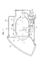
- FIG. 1 is a schematic sectional view illustrating the internal structure of a headlamp 210 for use in a vehicle headlamp system 100 according to an embodiment of the present invention.
- FIG. 1 is a sectional view of the headlamp 210 seen from the left side, sectioned along a vertical plane containing the optical axis X of the lamp thereof.
- the headlamp 210 is a variable light distribution type headlamp disposed at each of the left and right sides of a vehicle in the width direction thereof. Since the vehicle headlamp disposed on the left side is substantially the same in structure to that disposed on the right side, they are described without particularly distinguishing between them.
- the headlamp 210 has a lamp chamber 216 formed of a lamp body 212 having an opening section being open in the forward direction of the vehicle and a transparent cover 214 for covering the opening section of this lamp body 212.
- a lamp unit 10 for emitting light in the forward direction of the vehicle is accommodated in the lamp chamber 216.
- a lamp bracket 218 has a pivot mechanism 218a around which the lamp unit 10 can pivot.
- the lamp bracket 218 is connected to a body bracket 220 standing on the inner wall face of the lamp body 212 using a fastening member, such as a screw.
- the lamp unit 10 is secured at a predetermined position inside the lamp chamber 216.
- the lamp unit 10 can tilt around the pivot mechanism 218a and its orientation can be changed to a forwardly inclined orientation or a rearwardly inclined orientation, for example.
- the rotation shaft 222a of a swivel actuator 222 for an adaptive front-lighting system (AFS) for emitting light in the traveling direction of the vehicle when the vehicle travels on a curved road, for example, is secured to the lower face of the lamp unit 10.
- the swivel actuator 222 swivels the lamp unit 10 around the pivot mechanism 218a in the traveling direction of the vehicle on the basis of the data of the steering amount provided from the vehicle, the data of the road shape provided from a navigation system, a positional relationship to the forward vehicle, etc.
- the swivel actuator 222 can be formed of a stepping motor, for example.
- the swiveling angle of the mechanism has a fixed value, it is possible to use a solenoid, for example.
- the swivel actuator 222 is secured to a unit bracket 224.
- a leveling actuator 226 disposed outside the lamp body 212 is connected to the unit bracket 224.
- the leveling actuator 226 is formed of, for example, a motor that is used to extend and retract the rod 226a thereof in the directions indicated by arrows M and N.
- the lamp unit 10 is tilted around the pivot mechanism 218a so as to have the rearwardly inclined orientation.
- the lamp unit 10 is tilted around the pivot mechanism 218a so as to have the forwardly inclined orientation.
- leveling adjustment for directing the optical axis thereof upward can be carried out. Furthermore, when the lamp unit 10 has the forwardly inclined orientation, leveling adjustment for directing the optical axis downward can be carried out.
- the optical axis can thus be adjusted depending on the orientation of the vehicle by carrying out the leveling adjustment in this way. As a result, the travel distance of the light emitted forward from the headlamp 210 can be adjusted to an optimal distance.
- a lamp control unit 40 for controlling the ON/OFF operation of the lamp unit 10 and for controlling the formation of a light distribution pattern is disposed on the inner wall face of the lamp chamber 216, for example, below the lamp unit 10. This lamp control unit 40 also controls the operations of the swivel actuator 222 and the leveling actuator 226.
- the lamp unit 10 is formed of a shade mechanism 18 including a rotary shade 12, a light source 14 serving as a light source, a lamp housing 17 for supporting a reflector 16 on the inner wall thereof, and a projection lens 20.
- a shade mechanism 18 including a rotary shade 12, a light source 14 serving as a light source, a lamp housing 17 for supporting a reflector 16 on the inner wall thereof, and a projection lens 20.
- an incandescent lamp, a halogen lamp, a discharge lamp or an LED lamp can be used as the light source 14.
- a halogen lamp is used as the light source 14
- the reflector 16 reflects the light emitted from the light source 14. Part of the light emitted from the light source 14 and part of the light reflected by the reflector 16 are guided to the projection lens 20 via the rotary shade 12 constituting the shade mechanism 18.
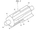
- FIG. 2 is a schematic perspective view showing the rotary shade 12.
- the rotary shade 12 is a cylindrical member that is rotated around the rotation shaft 12a thereof by a shade motor (a shade actuator 28 shown in FIG. 3 ).
- the rotary shade 12 has a cutout portion 22 obtained by partially cutting out the rotary shade 12 in the axial direction thereof, and a plurality of shade plates 24 disposed on the outer circumferential face 12b other than the face of the cutout portion 22.
- the cutout portion 22 or one of the shade plates 24 of the rotary shade 12 can be moved to the position of the rear focal plane including the rear focal point of the projection lens 20 depending on the rotation angle of the rotary shade 12.
- a light distribution pattern corresponding to the shape of the ridge line portion of the shade plate 24 positioned on the optical axis X is formed depending on the rotation angle of the rotary shade 12.
- a low beam light distribution pattern or a light distribution pattern partially having the characteristic of the low beam light distribution pattern is formed by moving one of the shade plates 24 of the rotary shade 12 to the optical axis X and by shielding part of the light emitted from the light source 14.
- a high beam light distribution pattern is formed by moving the cutout portion 22 to the optical axis X so that the light emitted from the light source 14 is not shielded.
- the rotary shade 12 is driven by a motor, for example, so as to be rotatable.
- One of the shade plates 24 for forming a desired light distribution pattern or the cutout portion 22 is moved onto the optical axis X by controlling the rotation amount of the motor.
- the rotary shade 12 may be provided with only a light-shielding function by eliminating the cutout portion 22 from the outer circumferential face 12b of the rotary shade 12.
- the rotary shade 12 is retracted from the position of the optical axis X by driving a solenoid, for example. With this configuration, even if the motor for rotating the rotary shade 12 fails, the light distribution pattern is fixed to the low beam light distribution pattern or a light distribution pattern similar thereto. In other words, a situation in which the rotary shade 12 is fixed at an angle at which the high beam light distribution pattern is formed can be avoided securely, and a fail-safe function can be realized.
- the projection lens 20 is disposed on the optical axis X extending in the front-rear direction of the vehicle, and the light source 14 is disposed behind the rear focal plane of the projection lens 20.
- the projection lens 20 is formed of a plane-convex aspheric lens in which the surface on the front side is a convex face and the surface on the rear side is a plane face.
- the projection lens 20 projects a light source image formed on the rear focal plane thereof on an imaginary vertical screen disposed ahead of the lamp unit 10 as a reverted image.
- FIG. 3 is a view showing a configuration of the vehicle headlamp system 100 including the headlamps 210 configured as described above, a control device 50 for determining the light distribution pattern to be formed by the headlamps 210, and various input devices for supplying input information to the control device 50. While only one headlamp 210 is illustrated in FIG. 3 , the control device controls both of the right and left headlamps 210.
- the lamp control unit 40 may not be provided in each of the headlamps 210, and may be provided outside the headlamps 210 and may be configured as a common control unit for both of the right and left headlamps 210.
- the respective blocks of the control device 50 can be accomplished by hardware using devices, such as the CPU and memory of a computer, and accomplished by software using computer programs, etc. loaded into the memory.
- the blocks herein indicate function blocks that are accomplished by the cooperation among them. For this reason, it will be understood by those skilled in the art that these function blocks can be accomplished in various ways by the combination of hardware and software.
- a wiper switch 102 a fog lamp switch 104, a raindrop sensor 106, a camera 30 (an imaging device), a vehicle speed sensor 108, and a navigation system 110 are included as the input devices.
- the wiper switch 102 is a switch that is operated by the driver of the vehicle to turn ON/OFF a wiper apparatus (not shown) installed in the vehicle.
- the fog lamp switch 104 is a switch that is operated by the driver to turn ON/OFF a fog lamp (not shown) installed in the vehicle.
- the raindrop sensor 106 is a sensor for judging whether the weather is rainy by applying light to the windshield and by detecting the light reflected thereby. The raindrop sensor 106 is not required to be installed.
- the camera 30 is mounted on the vehicle to capture an image of a region ahead of the vehicle so as to serve as object recognizing means for detecting objects, such as a preceding vehicle, an oncoming vehicle and a pedestrian.
- the camera 30 may be a camera dedicatedly controlled by the control device 50 or may be a camera shared by another system.
- the vehicle speed sensor 108 is a sensor disposed in the vicinity of a wheel (not shown) of the vehicle to detect the rotation speed of the wheel, thereby obtaining the speed of the vehicle.
- the navigation system 110 is a system for providing various kinds of information around the vehicle by using a vehicle position detection section, such as a GPS (global positioning system), and map data prepared in advance.
- the control device 50 instructs the headlamp 210 to generate an appropriate light distribution pattern.
- the control device 50 includes a weather judging section 52, a pattern determining section 54, a map storage section 56, a signal output section 58, a vehicle detecting section 62, and a traveling location judging section 64.
- the weather judging section 52 judges whether the weather in the area in which the vehicle travels is bad weather.
- "Bad weather” is defined as a weather condition in which the vehicle detecting section 62 may cause a detection error when detecting the position of the forward vehicle on the basis of image data. More specifically, bad weather is defined as a weather condition in which forward visibility is directly impaired by rain, fog, snow, etc. or water that may cause diffused reflection of light is present on the road surface, etc.
- the weather judging section 52 judges whether the weather is bad weather on the basis of the information from the wiper switch 102, the fog lamp switch 104 or the raindrop sensor 106. More specifically, the weather judging section 52 judges that the weather is bad weather when the wiper switch 102 or the fog lamp switch 104 is at its ON state. Alternatively, the weather judging section 52 judges that the weather is bad weather when raindrops are detected on the windshield by the raindrop sensor 106. The weather judging section 52 may judge that the weather is bad weather when the period during which raindrops were detected by the raindrop sensor 106 has reached a predetermined value or more so as not to judge that the weather is bad weather when the windshield is temporarily cleaned by the wiper apparatus. The weather judging section 52 may also judge that the weather is bad weather when the speed of the wiper blade of the wiper apparatus has reached a predetermined value or more so as not to judge that the weather is bad weather when slight rain falls, for example.
- the vehicle detecting section 62 Upon receiving the image data obtained by taking an image of a region ahead of the vehicle using the camera 30, the vehicle detecting section 62 detects the position of the forward vehicle by searching for characteristics indicating vehicles in the image data. Since this kind of method for detecting the position of the forward vehicle is known, the detailed description thereof is omitted.
- the traveling location judging section 64 judges whether the area in which the vehicle is traveling is an urban area.
- the traveling location judging section 64 includes a vehicle-based judging section 66 and an environment-based judging section 68.
- "Urban area” is an area in which there are relatively large amounts of light sources other than those of the forward vehicle and an area conforming to the following conditions.
- the vehicle-based judging section 66 judges whether the vehicle is traveling in an urban area on the basis of the number of times the vehicle stops. More specifically, the vehicle-based judging section 66 counts the number of times the vehicle stopped per unit time on the basis of the change in the output from the vehicle speed sensor 108 or the operation of the brake pedal (not shown), for example. In the case that the vehicle stopped two or more times in five minutes, for example, the vehicle-based judging section 66 judges that the vehicle is traveling in an urban area. This judgment is based on the fact that the vehicle stops frequently at red traffic lights and in traffic jams when the vehicle is traveling in an urban area.
- the vehicle-based judging section 66 may also judge whether the vehicle is traveling in an urban area on the basis of the average speed of the vehicle instead of the number of times the vehicle stops. More specifically, the vehicle-based judging section 66 calculates the average speed of the vehicle by performing moving average processing on the speed information from the vehicle speed sensor 108 at predetermined time intervals. For example, in the case that the average speed of the vehicle is 30 km/h or less, the vehicle-based judging section 66 judges that the vehicle is traveling in an urban area. This judgment is based on the fact that the speed of the vehicle decreases because of red traffic lights, traffic jams, etc. when the vehicle is traveling in an urban area.
- the environment-based judging section 68 judges whether the vehicle is traveling in an urban area on the basis of image data taken by the camera 30. More specifically, the environment-based judging section 68 analyzes the image data and obtains one or more of the following: the number of traffic lights or the distance therebetween, the number of street lights or the distance therebetween, and the number of pedestrian crosswalks or the distance therebetween. These may be obtained by matching the sample image of a traffic light or a pedestrian crosswalk with the image data from the camera 30 or by detecting a color (i.e., green, yellow or red for traffic lights, and white for pedestrian crosswalks) from the image data. The number of street lights or distance therebetween may be obtained by detecting the number of light spots in the image data. Any known image processing techniques can be used to detect these.
- the environment-based judging section 68 judges that the vehicle is traveling in an urban area. This judgment is based on the fact that the numbers of traffic lights, street lights and pedestrian crosswalks in an urban area are larger than those in a suburban area.
- the environment-based judging section 68 judges whether the vehicle is traveling in an urban area on the basis of the average luminance of the image data taken by the camera 30. More specifically, the environment-based judging section 68 calculates the average luminance of a range other than a predetermined range on the basis of the image data.
- the predetermined range is a road surface, for example.
- the average luminance is obtained by averaging the luminance values of the respective pixels constituting the image data. In the case that the average luminance is equal to a predetermined upper limit value or more, the environment-based judging section 68 judges that the vehicle is traveling in an urban area. This judgment is based on the fact that numerous light sources, such as street lights and building illuminations, are present around the vehicle in an urban area and that the average luminance of an image in an urban area is higher than that of an image in a suburban area.
- the environment-based judging section 68 may judge whether the vehicle is traveling in an urban area on the basis of the information obtained from the navigation system 110. More specifically, the environment-based judging section 68 refers to the map data of the road on which the vehicle is traveling and obtains the number of traffic lights or the distance therebetween, the number of street lights or the distance therebetween, and the number of pedestrian crosswalks or the distance therebetween along the road. In the case that any one or predetermined two or more of these values are predetermined upper limit values or more, the environment-based judging section 68 judges that the vehicle is traveling in an urban area.
- the traveling location judging section 64 transmits this judgment information to the pattern determining section 54.
- the pattern determining section 54 basically determines a light distribution pattern formed by the left and right headlamps 210 so that the area ahead of the vehicle is irradiated by the light having an optimal light distribution pattern depending on the presence of the forward vehicle and the change of the position of the forward vehicle detected by the vehicle detecting section 62.
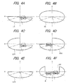
- FIGS. 4A to 4F are views showing light distribution patterns to be selected by the pattern determining section 54 and capable of being formed by the headlamps 210.
- FIGS. 4A to 4F show light distribution patterns formed on the imaginary vertical screen disposed 25 m ahead of the headlamps 210.
- the light distribution patterns shown in FIGS. 4A to 4F are combined light distribution patterns, each being formed by superimposing the light distribution patterns respectively formed by the headlamps 210 disposed on the left and right sides of the vehicle in the width direction thereof.
- FIGS. 4A shows a low beam light distribution pattern Lo.
- This low beam light distribution pattern Lo is a light distribution pattern designed in consideration of not giving glare to a forward vehicle and a pedestrian when the vehicle travels in a left-hand traffic lane.
- the low beam light distribution pattern Lo has an oncoming lane side cutoff line located at the upper end thereof and extending in parallel with the horizontal line H on the right side of the vertical line V; an ongoing lane side cutoff line located at a position higher than that of the oncoming lane side cutoff line and extending in parallel with the horizontal line H on the left side of the vertical line V; and an oblique cutoff line disposed between the oncoming lane side cutoff line and the ongoing lane side cutoff line so as to be connected to the two cutoff lines.
- the oblique cutoff line extends from the intersection of the oncoming lane side cutoff line and the V-V line upward in a left oblique direction at an oblique angle of 45°.
- FIG. 4B shows a high beam light distribution pattern Hi.
- This high beam light distribution pattern Hi is a light distribution pattern for illuminating a forward wide range and a remote distance and is formed in the case that it is not necessary to consider glare that is given to a forward vehicle and a pedestrian, for example.
- FIG. 4C shows a left-side high beam light distribution pattern LHi that is used in a left-hand traffic region.
- the left-side high beam light distribution pattern LHi is a special high beam light distribution pattern in which the pattern on the oncoming lane side of the high beam light distribution pattern Hi is shielded when the vehicle travels in a left-hand traffic lane and only the pattern on the ongoing lane side is illuminated by the high beam area.
- the left-side high beam light distribution pattern LHi is formed by synthesizing the left-side high beam light distribution pattern formed by the left headlamp 210 with the low beam light distribution pattern formed by the right headlamp 210.
- the left-side high beam light distribution pattern LHi is suitable when neither preceding vehicle nor pedestrian is present on the ongoing lane side and an oncoming vehicle or a pedestrian is present on the oncoming lane side. That is, the left-side high beam light distribution pattern LHi is designed such that glare is not given to the driver of the oncoming vehicle or the pedestrian in the oncoming lane while the forward visibility of the driver of the vehicle is improved.
- FIG. 4D shows a right-side high beam light distribution pattern RHi that is used in a left-hand traffic region.
- the right-side high beam light distribution pattern RHi is a special high beam light distribution pattern in which the pattern on the ongoing lane side of the high beam light distribution pattern Hi is shielded when the vehicle travels in the left-hand traffic lane and only the pattern on the oncoming lane side is illuminated by the high beam area.
- the right-side high beam light distribution pattern RHi is formed by synthesizing the right-side high beam light distribution pattern formed by the right headlamp 210 with the low beam light distribution pattern formed by the left headlamp 210.
- the right-side high beam light distribution pattern RHi is suitable when a preceding vehicle or a pedestrian is present on the ongoing lane side and neither oncoming vehicle nor pedestrian is present on the oncoming lane side. That is, the right-side high beam light distribution pattern RHi is designed such that glare is not given to the driver of the preceding vehicle or the pedestrian in the ongoing lane while the forward visibility of the driver of the vehicle is improved.
- FIG. 4E shows a V-beam light distribution pattern LoV in which the light to be applied to the vicinity of the intersection of the vertical line V and the horizontal line H on the imaginary vertical screen is suppressed.
- this V-beam light distribution pattern LoV is formed as described below.
- the low beam light distribution pattern shown in FIG. 4A is formed using the left headlamp 210.
- the low beam light distribution pattern that is used in a right-hand traffic region is formed using the right headlamp 210.
- a light distribution pattern being symmetric with the light distribution pattern shown in FIG. 4A with respect to the vertical line V is formed.
- the V-beam light distribution pattern LoV is capable of allowing the driver of the vehicle to easily recognize obstacles, etc. on the road shoulders on the ongoing lane side and the oncoming lane side while suppressing glare to the driver of the distant oncoming vehicle.
- FIG. 4F shows a split light distribution pattern S.
- This split light distribution pattern S is a special high beam light distribution pattern having a light-shielding area UA in the central section thereof above the horizontal line H and having high beam areas on both sides of the light-shielding area UA in the horizontal direction.
- the split light distribution pattern S can be formed by superimposing the left-side high beam light distribution pattern formed using the left headlamp 210 and the right-side high beam light distribution pattern formed using the right headlamps 210.
- the two light distribution patterns described above are superimposed so that the high beam area of the left-side high beam light distribution pattern does not make contact with the high beam area of the right-side high beam light distribution pattern, whereby he light-shielding area UA is formed.
- the range of the light-shielding area UA can be changed in the horizontal direction by swiveling the left and right headlamps 210 so that at least one of the left-side high beam light distribution pattern and the right-side high beam light distribution pattern is moved in the horizontal direction.
- combined light distribution patterns having any shapes can be formed by combining shades having shapes different between the left and right headlamps 210. Since this kind of ADB system itself, which is capable of changing the light distribution pattern depending on the position of the forward vehicle, is known, no further detailed description is provided in this specification.
- the map storage section 56 is configured to hold a plurality of maps that are used to select light distribution patterns to be formed by the headlamps 70 on the basis of the position of the forward vehicle.
- the map storage section 56 holds a basic map56a, a weather adapted map 56b and an urban adapted map 56c.
- Each of these maps may be a two-dimensional map in which a light distribution pattern is determined depending on the horizontal and vertical positions of the forward vehicle appearing in an image of an area ahead of the vehicle.
- each of the maps may be a table-type map characterized in that the image of the area ahead of the vehicle is divided into a plurality of sections and that a light distribution pattern is determined for each section in which the forward vehicle is positioned. Since the maps themselves are known, no further detailed description is provided in this specification.
- the pattern determining section 54 limits the level of the cutoff line, the luminance, etc. of the light distribution pattern. More specifically, the pattern determining section 54 refers to the weather adapted map 56b stored in the map storage section 56 and selects a light distribution pattern corresponding to the position of the forward vehicle detected by the vehicle detecting section 62.
- the weather adapted map 56b is formed so as to have the following characteristics, for example.
- the light distribution pattern to be used during normal weather and the light distribution pattern to be used during bad weather are made different from each other because of the following reasons. That is, during bad weather, such as rain, snow or dense fog, forward visibility is lowered, and the tail lamps of the preceding vehicle and the headlamps of the oncoming vehicle cannot be detected accurately from the captured images sometimes.
- the high beam light distribution pattern is selected by the ADB system.
- the driver of the forward vehicle may receive a glare, or an optical film phenomenon in which the irradiation light is reflected by the water on the road surface may occur, which would blind the driver of the vehicle.
- the high beam light distribution pattern is not selected or the illuminance thereof is lowered during bad weather, whereby glare to the driver of the forward vehicle can be suppressed and the occurrence of the optical film phenomenon can be prevented.
- the pattern determining section 54 imposes limitations, such as the stoppage of the ADB system itself or the avoidance of the use of specific light distribution patterns. More specifically, the pattern determining section 54 refers to the urban adapted map 56c stored in the map storage section 56 and selects a light distribution pattern corresponding to the position of the forward vehicle detected by the vehicle detecting section 62.
- the urban adapted map 56c is formed so as to have the following characteristics, for example.
- the light distribution pattern is changed as described above when the vehicle is traveling in an urban area because of the following reasons. That is, numerous light sources, such as street lights and building illuminations, other than the lamps of vehicles are present in an urban area at night, whereby an error is apt to occur when detecting the position of the forward vehicle because of the presence of these light sources. Since the light distribution pattern is switched each time the position of the forward vehicle is detected erroneously, this switching occurs frequently. As a result, there is a danger that an uncomfortable feeling is given to the driver of the vehicle or glare is given to the drivers of the other vehicles or pedestrians. Hence, the operation of the ADB system is stopped or the use of some light distribution patterns is prohibited to reduce the number of times the light distribution pattern is switched. As a result, the uncomfortable feeling to the driver is reduced and the generation of glare is suppressed.
- numerous light sources such as street lights and building illuminations, other than the lamps of vehicles are present in an urban area at night, whereby an error is apt to occur when detecting the position of the
- the signal output section 58 outputs a corresponding control signal to the lamp control unit 40 of the headlamp 210 so that the light distribution pattern determined by the pattern determining section 54 is formed.
- the headlamp 210 includes the lamp control unit 40, a power circuit 60, a shade motor 28, the swivel actuator 222, and the light source 14.
- the lamp control unit 40 receives the signal from the control device 50 and controls the shade motor 28, the swivel actuator 222 and the light source 14 through the power circuit 60 so that the determined light distribution pattern is formed by the headlamp.
- the pattern determining section 54 refers to the weather adapted map 56b and selects a light distribution pattern to be formed by the headlamps 210.
- the pattern determining section 54 refers to the urban adapted map 56c and selects a light distribution pattern to be formed by the headlamps 210.
- the pattern determining section 54 refers to the basic map56a and selects a light distribution pattern to be formed by the headlamps 210.
- the lamp control unit 40 controls the headlamps 70 so that the selected light distribution pattern is formed.
- FIG. 5 is a flowchart of a light distribution pattern control according to this embodiment. The processing of this flowchart is executed repeatedly at predetermined time intervals in the control device 50.
- the weather judging section 52 judges whether the weather in the area in which the vehicle is traveling is bad weather on the basis of the information from the wiper switch 102, the fog lamp switch 104 or the raindrop sensor 106 (S10).
- the pattern determining section 54 determines a combined light distribution pattern to be formed by the headlamps 70 on the basis of the weather adapted map 56b inside the map storage section 56 and the position of the forward vehicle (S14).
- the traveling location judging section 64 judges whether the vehicle is traveling in an urban area (S12).
- the pattern determining section 54 determines a combined light distribution pattern to be formed by the headlamps 70 on the basis of the urban adapted map 56c inside the map storage section 56 and the position of the forward vehicle (S16). In the case that it is judged that the vehicle is not traveling in an urban area (S12; N), the pattern determining section 54 determines a combined light distribution pattern to be formed by the headlamps 70 on the basis of the basic map56a inside the map storage section 56 and the position of the forward vehicle (S18).
- the vehicle headlamp system having a function capable of changing the light distribution patterns and the light distribution directions of the headlamps on the basis of the position of the forward vehicle detected from an image obtained by taking an image of a region ahead of the vehicle, the formation of specific light distribution patterns can be prohibited depending on the weather. Hence, it is possible to prevent a situation in which the light distribution pattern is changed inappropriately because the position of the forward vehicle cannot be detected accurately owing to the influence of bad weather.
- the traveling location judging section 64 may judge whether the vehicle is traveling on a motorway, instead of, or in addition to the judgment of whether the vehicle is traveling in an urban area.
- the traveling location judging section 64 may judge that the vehicle is traveling on a motorway when the vehicle speed obtained by the vehicle speed sensor 108 is a predetermined speed or more.
- the traveling location judging section 64 may judge that the vehicle is traveling on a motorway on the basis of the vehicle position information obtained from navigation system 110.
- the pattern determining section 54 selects a motorway high beam light distribution pattern in which the amount of beam diffusion in the upward direction is made smaller than that of the basic high beam, instead of the light distribution pattern control based on the above-mentioned normal, weather map.
- FIG. 6 shows an example of a basic high beam light distribution pattern J1 and an example of a motorway high beam light distribution pattern J2.
- the irradiation range above the horizontal line is reduced. This reduction is based on the fact that the amount of beam diffusion of the high beam light distribution pattern in the upward direction can be made smaller than that of the basic high beam light distribution pattern because anti-dazzle fences are installed along a motorway and it is enough that the driver of the vehicle can see only the road surface and guard rails.
- this reduction even if a truck or the like, the eye level of the driver thereof is higher than the height of the anti-dazzle fences, is present in the oncoming lane, there is no danger of giving glare to the driver.
- FIG. 7 is a view illustrating a shade structure for forming the motorway high beam light distribution pattern.
- the internal structure of the headlamp 210 shown in FIG. 7 is similar to that of the headlamp 210 shown in FIG. 1 except that a movable shade 13 being movable in the up-down direction is provided instead of the rotary shade.
- a shade actuator When the movable shade 13 is moved to its uppermost position by a shade actuator, the basic high beam light distribution pattern is formed.
- the motorway high beam light distribution pattern is formed.
- the movable shade 13 is moved to its lowermost position, the low beam light distribution pattern is formed.
- the headlamp 210 is configured to have both the rotary shade 12 shown in FIG. 1 and the movable shade 13 shown in FIG. 7 .
- the left-side high beam light distribution pattern and the right-side high beam light distribution pattern are described referring to FIGS. 4C and 4D .
- a combined light distribution pattern may be formed in which the level of the cutoff line of the light distribution pattern of the right headlamp for forming a one-side high beam combined light distribution pattern on the ongoing lane side is set so as not to be higher than the horizontal line.
- FIG. 8 is a diagram showing a comparison between right-side high beam combined light distribution patterns according to the conventional art and that according to this embodiment.
- (a) and (b) show the right-side high beam combined light distribution patterns according to the conventional art
- (c) shows the right-side high beam combined light distribution patterns according to this embodiment.
- “LH” represents a high beam light distribution pattern formed only by the left headlamp 210
- “RH” represents a high beam light distribution pattern formed only by the right headlamp 210
- “Combined” represents a combined light distribution pattern formed by the left and right headlamps 210.
- FIG. 8 is a diagram showing a comparison between right-side high beam combined light distribution patterns according to the conventional art and that according to this embodiment.
- LH represents a high beam light distribution pattern formed only by the left headlamp 210
- “RH” represents a high beam light distribution pattern formed only by the right headlamp 210
- “Combined” represents a combined light distribution pattern formed by the left and right headlamps 210.
- the combined light distribution pattern shown in (a) of FIG. 8 is examined in which the ongoing lane side (the left side in a left-hand traffic region) of the left high beam light distribution pattern LH includes a range higher than the horizontal line and the ongoing lane side of the right high beam light distribution pattern RH includes only a range lower than the horizontal line.
- the range F can be irradiated only by the left lamp, whereby the long distance visibility in the ongoing lane is not high. Hence, "x" is indicated.
- the split light distribution pattern is formed, the area around an oncoming vehicle C is not illuminated, whereby no glare is given to the driver of the oncoming vehicle. Hence, "o" is indicated.
- the combined light distribution pattern shown in (b) of FIG. 8 is examined in which the ongoing lane side (the left side in a left-hand traffic region) of the left high beam light distribution pattern LH includes a range higher than the horizontal line and the ongoing lane side of the right high beam light distribution pattern RH also includes a range higher than the horizontal line.
- the range F is irradiated by the left and right lamps (two lamps), whereby the long distance visibility in the ongoing lane is high. Hence, "o” is indicated.
- the split light distribution pattern is formed, the area around the oncoming vehicle C is illuminated eventually. As a result, glare is given to the driver of the oncoming vehicle. Hence, "x" is indicated.
- the combined light distribution pattern shown in (c) of FIG. 8 is characterized in that the ongoing lane side of the right high beam light distribution pattern RH has a shape, the cutoff line of which is slightly lower than the horizontal line, although the left high beam light distribution pattern LH is the same as those shown in (a) and (b).
- the combined light distribution pattern formed in this case is examined.
- the range F is irradiated by the left and right lamps (two lamps), whereby the long distance visibility in the ongoing lane is high. Hence, "o" is indicated.
- the split light distribution pattern is formed, the area around the oncoming vehicle C is not illuminated, whereby glare is not given to the driver of the oncoming vehicle. Hence, "o" is indicated.
Landscapes
- Engineering & Computer Science (AREA)
- Mechanical Engineering (AREA)
- Lighting Device Outwards From Vehicle And Optical Signal (AREA)
Abstract
Description
- The present invention relates to a control device, a vehicle headlamp, and a vehicle headlamp system configured to change a light distribution pattern in accordance with a condition of a vehicle or an environment surrounding the vehicle.
-
JP 2009-179113 A JP 2009-227088 A JP 2010-000957 A - In recognizing a forward vehicle at night, cameras are advantageous than radars such as laser radars and milliwave radars in that more distant vehicles can be detected by recognizing light spots in an image taken by the camera.
- However, when driving in bad weather or in an area, such as an urban area, a forward vehicle may not be accurately detected from an image taken by the camera due to disturbance light. Therefore, when a light irradiation system like the ADB system is operated under such conditions, it may cause a glare for other drivers in front of the vehicle.
- The present invention has been made with a view to preventing an unsuitable light distribution pattern from being selected in a vehicle headlamp system configured to change a light distribution pattern on the basis of a position of a forward vehicle detected from image data.
- According to an aspect of the present invention, a control device, a vehicle headlamp, and a vehicle headlamp system are provided. The control device, the vehicle headlamp, and vehicle headlamp system are interrelated to each other.
- The control device comprises a vehicle detecting section configured to receive image data obtained by taking an image of a region in front of a vehicle, and to detect a forward vehicle and a position of the forward vehicle on the basis of the image data, a map storage section, a pattern determining section configured to determine a light distribution pattern to be formed by a vehicle headlamp on the basis of the position of the forward vehicle and with reference to the map storage section, and an output section configured to output a control signal to the vehicle headlamp so that the light distribution pattern determined by the pattern determining section is formed. The control device further comprises a weather judging section configured to judge whether an environment in which the vehicle is traveling is in a weather condition that can cause an error in detecting the position of the forward vehicle. The map storage section is configured to store a plurality of maps are for selecting the light distribution pattern to be formed by the vehicle headlamp on the basis of the position of the forward vehicle, wherein the plurality of maps includes a basic map and a weather adapted map, the weather adapted map being adapted to be used in said weather condition. The pattern determining section refers to the basic map to determine the light distribution pattern when the weather judging section judges that the environment is not in said weather condition, and refers to the weather adapted map to determine the light distribution pattern when the weather judging section judges that the environment is in said weather condition.
- The vehicle headlamp is adapted to be controlled by the control device. The vehicle headlamp comprises a light source, a shade mechanism configured to form a plurality of light distribution patterns by shielding light from the light source, a shade actuator configured to move the shade mechanism. and a swivel actuator configured to swivel a lamp unit comprising the light source, the shade mechanism, and the shade actuator. Upon receipt of the control signal from the control device, at least one of the light source, the shade actuator and the swivel actuator are controlled to form the light distribution pattern determined by the pattern determining section.
- The vehicle headlamp system comprises an imaging device configured to take an image of a region in front of a vehicle, the control device, and the vehicle headlamp. The image taken by the imaging device is sent to the vehicle detecting section as the image data.
- Other aspects and advantages of the present invention will be apparent from the following description, the drawings and the claims.
- Hereinafter, exemplary embodiments of the present invention will be described in detail with reference to the drawings including:
- FIG. 1:
- a sectional view of a headlamp of a vehicle headlamp system according to an embodiment of the present invention;
- FIG. 2:
- a perspective view of a rotary shade of the headlamp;
- FIG. 3:
- a block diagram of the vehicle headlamp system including the headlamp, a control device for controlling light irradiation of the headlamp, and various input devices for supplying input information to the control device;
- FIGS. 4A to 4F:
- diagrams showing examples of light distribution patterns to be selected by a pattern determining section;
- FIG. 5:
- a flowchart of an example of a light distribution pattern control;
- FIG. 6:
- a diagram illustrating an example of a basic high beam light distribution pattern and an example of a motorway high beam light distribution pattern;
- FIG. 7:
- a sectional view of a headlamp having a shade mechanism for forming the motorway high beam light distribution pattern; and
- FIG. 8:
- a diagram showing a comparison between right-side high beam combined light distribution patterns according to the conventional art and an embodiment of the present invention.
-
FIG. 1 is a schematic sectional view illustrating the internal structure of aheadlamp 210 for use in avehicle headlamp system 100 according to an embodiment of the present invention.FIG. 1 is a sectional view of theheadlamp 210 seen from the left side, sectioned along a vertical plane containing the optical axis X of the lamp thereof. Theheadlamp 210 is a variable light distribution type headlamp disposed at each of the left and right sides of a vehicle in the width direction thereof. Since the vehicle headlamp disposed on the left side is substantially the same in structure to that disposed on the right side, they are described without particularly distinguishing between them. - The
headlamp 210 has alamp chamber 216 formed of alamp body 212 having an opening section being open in the forward direction of the vehicle and atransparent cover 214 for covering the opening section of thislamp body 212. Alamp unit 10 for emitting light in the forward direction of the vehicle is accommodated in thelamp chamber 216. Alamp bracket 218 has apivot mechanism 218a around which thelamp unit 10 can pivot. Thelamp bracket 218 is connected to abody bracket 220 standing on the inner wall face of thelamp body 212 using a fastening member, such as a screw. Hence, thelamp unit 10 is secured at a predetermined position inside thelamp chamber 216. In addition, thelamp unit 10 can tilt around thepivot mechanism 218a and its orientation can be changed to a forwardly inclined orientation or a rearwardly inclined orientation, for example. - Furthermore, the
rotation shaft 222a of aswivel actuator 222 for an adaptive front-lighting system (AFS) for emitting light in the traveling direction of the vehicle when the vehicle travels on a curved road, for example, is secured to the lower face of thelamp unit 10. Theswivel actuator 222 swivels thelamp unit 10 around thepivot mechanism 218a in the traveling direction of the vehicle on the basis of the data of the steering amount provided from the vehicle, the data of the road shape provided from a navigation system, a positional relationship to the forward vehicle, etc. As a result, the area illuminated by thelamp unit 10 is directed ahead of the curved road instead of the forward area of the vehicle, whereby the front visual field of the driver of the vehicle is improved. Theswivel actuator 222 can be formed of a stepping motor, for example. In the case that the swiveling angle of the mechanism has a fixed value, it is possible to use a solenoid, for example. - The
swivel actuator 222 is secured to aunit bracket 224. A levelingactuator 226 disposed outside thelamp body 212 is connected to theunit bracket 224. The levelingactuator 226 is formed of, for example, a motor that is used to extend and retract therod 226a thereof in the directions indicated by arrows M and N. In the case that therod 226a is extended in the direction indicated by arrow M, thelamp unit 10 is tilted around thepivot mechanism 218a so as to have the rearwardly inclined orientation. Conversely, in the case that therod 226a is retracted in the direction indicated by arrow N, thelamp unit 10 is tilted around thepivot mechanism 218a so as to have the forwardly inclined orientation. When thelamp unit 10 has the rearwardly inclined orientation, leveling adjustment for directing the optical axis thereof upward can be carried out. Furthermore, when thelamp unit 10 has the forwardly inclined orientation, leveling adjustment for directing the optical axis downward can be carried out. The optical axis can thus be adjusted depending on the orientation of the vehicle by carrying out the leveling adjustment in this way. As a result, the travel distance of the light emitted forward from theheadlamp 210 can be adjusted to an optimal distance. - A
lamp control unit 40 for controlling the ON/OFF operation of thelamp unit 10 and for controlling the formation of a light distribution pattern is disposed on the inner wall face of thelamp chamber 216, for example, below thelamp unit 10. Thislamp control unit 40 also controls the operations of theswivel actuator 222 and the levelingactuator 226. - The
lamp unit 10 is formed of ashade mechanism 18 including arotary shade 12, alight source 14 serving as a light source, alamp housing 17 for supporting areflector 16 on the inner wall thereof, and aprojection lens 20. For example, an incandescent lamp, a halogen lamp, a discharge lamp or an LED lamp can be used as thelight source 14. In this embodiment, an example in which a halogen lamp is used as thelight source 14 is described. Thereflector 16 reflects the light emitted from thelight source 14. Part of the light emitted from thelight source 14 and part of the light reflected by thereflector 16 are guided to theprojection lens 20 via therotary shade 12 constituting theshade mechanism 18. -
FIG. 2 is a schematic perspective view showing therotary shade 12. Therotary shade 12 is a cylindrical member that is rotated around therotation shaft 12a thereof by a shade motor (ashade actuator 28 shown inFIG. 3 ). Therotary shade 12 has acutout portion 22 obtained by partially cutting out therotary shade 12 in the axial direction thereof, and a plurality ofshade plates 24 disposed on the outercircumferential face 12b other than the face of thecutout portion 22. Thecutout portion 22 or one of theshade plates 24 of therotary shade 12 can be moved to the position of the rear focal plane including the rear focal point of theprojection lens 20 depending on the rotation angle of therotary shade 12. Hence, a light distribution pattern corresponding to the shape of the ridge line portion of theshade plate 24 positioned on the optical axis X is formed depending on the rotation angle of therotary shade 12. For example, a low beam light distribution pattern or a light distribution pattern partially having the characteristic of the low beam light distribution pattern is formed by moving one of theshade plates 24 of therotary shade 12 to the optical axis X and by shielding part of the light emitted from thelight source 14. Furthermore, a high beam light distribution pattern is formed by moving thecutout portion 22 to the optical axis X so that the light emitted from thelight source 14 is not shielded. - The
rotary shade 12 is driven by a motor, for example, so as to be rotatable. One of theshade plates 24 for forming a desired light distribution pattern or thecutout portion 22 is moved onto the optical axis X by controlling the rotation amount of the motor. Therotary shade 12 may be provided with only a light-shielding function by eliminating thecutout portion 22 from the outercircumferential face 12b of therotary shade 12. Furthermore, in the case of forming the high beam light distribution pattern, therotary shade 12 is retracted from the position of the optical axis X by driving a solenoid, for example. With this configuration, even if the motor for rotating therotary shade 12 fails, the light distribution pattern is fixed to the low beam light distribution pattern or a light distribution pattern similar thereto. In other words, a situation in which therotary shade 12 is fixed at an angle at which the high beam light distribution pattern is formed can be avoided securely, and a fail-safe function can be realized. - The
projection lens 20 is disposed on the optical axis X extending in the front-rear direction of the vehicle, and thelight source 14 is disposed behind the rear focal plane of theprojection lens 20. Theprojection lens 20 is formed of a plane-convex aspheric lens in which the surface on the front side is a convex face and the surface on the rear side is a plane face. Theprojection lens 20 projects a light source image formed on the rear focal plane thereof on an imaginary vertical screen disposed ahead of thelamp unit 10 as a reverted image. -
FIG. 3 is a view showing a configuration of thevehicle headlamp system 100 including theheadlamps 210 configured as described above, acontrol device 50 for determining the light distribution pattern to be formed by theheadlamps 210, and various input devices for supplying input information to thecontrol device 50. While only oneheadlamp 210 is illustrated inFIG. 3 , the control device controls both of the right and leftheadlamps 210. Thelamp control unit 40 may not be provided in each of theheadlamps 210, and may be provided outside theheadlamps 210 and may be configured as a common control unit for both of the right and leftheadlamps 210. - Referring to
FIG. 3 , the respective blocks of thecontrol device 50 can be accomplished by hardware using devices, such as the CPU and memory of a computer, and accomplished by software using computer programs, etc. loaded into the memory. However, the blocks herein indicate function blocks that are accomplished by the cooperation among them. For this reason, it will be understood by those skilled in the art that these function blocks can be accomplished in various ways by the combination of hardware and software. - In this embodiment, a
wiper switch 102, afog lamp switch 104, araindrop sensor 106, a camera 30 (an imaging device), avehicle speed sensor 108, and anavigation system 110 are included as the input devices. - The
wiper switch 102 is a switch that is operated by the driver of the vehicle to turn ON/OFF a wiper apparatus (not shown) installed in the vehicle. Thefog lamp switch 104 is a switch that is operated by the driver to turn ON/OFF a fog lamp (not shown) installed in the vehicle. Theraindrop sensor 106 is a sensor for judging whether the weather is rainy by applying light to the windshield and by detecting the light reflected thereby. Theraindrop sensor 106 is not required to be installed. - The
camera 30 is mounted on the vehicle to capture an image of a region ahead of the vehicle so as to serve as object recognizing means for detecting objects, such as a preceding vehicle, an oncoming vehicle and a pedestrian. Thecamera 30 may be a camera dedicatedly controlled by thecontrol device 50 or may be a camera shared by another system. - The
vehicle speed sensor 108 is a sensor disposed in the vicinity of a wheel (not shown) of the vehicle to detect the rotation speed of the wheel, thereby obtaining the speed of the vehicle. Thenavigation system 110 is a system for providing various kinds of information around the vehicle by using a vehicle position detection section, such as a GPS (global positioning system), and map data prepared in advance. - Based on the information obtained from the above-mentioned various input devices, the
control device 50 instructs theheadlamp 210 to generate an appropriate light distribution pattern. Thecontrol device 50 includes aweather judging section 52, apattern determining section 54, amap storage section 56, asignal output section 58, avehicle detecting section 62, and a travelinglocation judging section 64. - The
weather judging section 52 judges whether the weather in the area in which the vehicle travels is bad weather. "Bad weather" is defined as a weather condition in which thevehicle detecting section 62 may cause a detection error when detecting the position of the forward vehicle on the basis of image data. More specifically, bad weather is defined as a weather condition in which forward visibility is directly impaired by rain, fog, snow, etc. or water that may cause diffused reflection of light is present on the road surface, etc. - The
weather judging section 52 judges whether the weather is bad weather on the basis of the information from thewiper switch 102, thefog lamp switch 104 or theraindrop sensor 106. More specifically, theweather judging section 52 judges that the weather is bad weather when thewiper switch 102 or thefog lamp switch 104 is at its ON state. Alternatively, theweather judging section 52 judges that the weather is bad weather when raindrops are detected on the windshield by theraindrop sensor 106. Theweather judging section 52 may judge that the weather is bad weather when the period during which raindrops were detected by theraindrop sensor 106 has reached a predetermined value or more so as not to judge that the weather is bad weather when the windshield is temporarily cleaned by the wiper apparatus. Theweather judging section 52 may also judge that the weather is bad weather when the speed of the wiper blade of the wiper apparatus has reached a predetermined value or more so as not to judge that the weather is bad weather when slight rain falls, for example. - Upon receiving the image data obtained by taking an image of a region ahead of the vehicle using the
camera 30, thevehicle detecting section 62 detects the position of the forward vehicle by searching for characteristics indicating vehicles in the image data. Since this kind of method for detecting the position of the forward vehicle is known, the detailed description thereof is omitted. - The traveling
location judging section 64 judges whether the area in which the vehicle is traveling is an urban area. The travelinglocation judging section 64 includes a vehicle-basedjudging section 66 and an environment-basedjudging section 68. "Urban area" is an area in which there are relatively large amounts of light sources other than those of the forward vehicle and an area conforming to the following conditions. - The vehicle-based
judging section 66 judges whether the vehicle is traveling in an urban area on the basis of the number of times the vehicle stops. More specifically, the vehicle-basedjudging section 66 counts the number of times the vehicle stopped per unit time on the basis of the change in the output from thevehicle speed sensor 108 or the operation of the brake pedal (not shown), for example. In the case that the vehicle stopped two or more times in five minutes, for example, the vehicle-basedjudging section 66 judges that the vehicle is traveling in an urban area. This judgment is based on the fact that the vehicle stops frequently at red traffic lights and in traffic jams when the vehicle is traveling in an urban area. - The vehicle-based
judging section 66 may also judge whether the vehicle is traveling in an urban area on the basis of the average speed of the vehicle instead of the number of times the vehicle stops. More specifically, the vehicle-basedjudging section 66 calculates the average speed of the vehicle by performing moving average processing on the speed information from thevehicle speed sensor 108 at predetermined time intervals. For example, in the case that the average speed of the vehicle is 30 km/h or less, the vehicle-basedjudging section 66 judges that the vehicle is traveling in an urban area. This judgment is based on the fact that the speed of the vehicle decreases because of red traffic lights, traffic jams, etc. when the vehicle is traveling in an urban area. - The environment-based
judging section 68 judges whether the vehicle is traveling in an urban area on the basis of image data taken by thecamera 30. More specifically, the environment-basedjudging section 68 analyzes the image data and obtains one or more of the following: the number of traffic lights or the distance therebetween, the number of street lights or the distance therebetween, and the number of pedestrian crosswalks or the distance therebetween. These may be obtained by matching the sample image of a traffic light or a pedestrian crosswalk with the image data from thecamera 30 or by detecting a color (i.e., green, yellow or red for traffic lights, and white for pedestrian crosswalks) from the image data. The number of street lights or distance therebetween may be obtained by detecting the number of light spots in the image data. Any known image processing techniques can be used to detect these. - In the case that any one or predetermined two or more of the number of traffic lights or the distance therebetween, the number of street lights or the distance therebetween, and the number of pedestrian crosswalks or the distance therebetween are predetermined upper limit values or more, the environment-based
judging section 68 judges that the vehicle is traveling in an urban area. This judgment is based on the fact that the numbers of traffic lights, street lights and pedestrian crosswalks in an urban area are larger than those in a suburban area. - The environment-based
judging section 68 judges whether the vehicle is traveling in an urban area on the basis of the average luminance of the image data taken by thecamera 30. More specifically, the environment-basedjudging section 68 calculates the average luminance of a range other than a predetermined range on the basis of the image data. The predetermined range is a road surface, for example. The average luminance is obtained by averaging the luminance values of the respective pixels constituting the image data. In the case that the average luminance is equal to a predetermined upper limit value or more, the environment-basedjudging section 68 judges that the vehicle is traveling in an urban area. This judgment is based on the fact that numerous light sources, such as street lights and building illuminations, are present around the vehicle in an urban area and that the average luminance of an image in an urban area is higher than that of an image in a suburban area. - Alternatively, the environment-based
judging section 68 may judge whether the vehicle is traveling in an urban area on the basis of the information obtained from thenavigation system 110. More specifically, the environment-basedjudging section 68 refers to the map data of the road on which the vehicle is traveling and obtains the number of traffic lights or the distance therebetween, the number of street lights or the distance therebetween, and the number of pedestrian crosswalks or the distance therebetween along the road. In the case that any one or predetermined two or more of these values are predetermined upper limit values or more, the environment-basedjudging section 68 judges that the vehicle is traveling in an urban area. - When it is judged that the vehicle is traveling in an urban area by one or both of the vehicle-based
judging section 66 and the environment-basedjudging section 68, the travelinglocation judging section 64 transmits this judgment information to thepattern determining section 54. - The
pattern determining section 54 basically determines a light distribution pattern formed by the left andright headlamps 210 so that the area ahead of the vehicle is irradiated by the light having an optimal light distribution pattern depending on the presence of the forward vehicle and the change of the position of the forward vehicle detected by thevehicle detecting section 62. -
FIGS. 4A to 4F are views showing light distribution patterns to be selected by thepattern determining section 54 and capable of being formed by theheadlamps 210.FIGS. 4A to 4F show light distribution patterns formed on the imaginary vertical screen disposed 25 m ahead of theheadlamps 210. The light distribution patterns shown inFIGS. 4A to 4F are combined light distribution patterns, each being formed by superimposing the light distribution patterns respectively formed by theheadlamps 210 disposed on the left and right sides of the vehicle in the width direction thereof. -
FIGS. 4A shows a low beam light distribution pattern Lo. This low beam light distribution pattern Lo is a light distribution pattern designed in consideration of not giving glare to a forward vehicle and a pedestrian when the vehicle travels in a left-hand traffic lane. The low beam light distribution pattern Lo has an oncoming lane side cutoff line located at the upper end thereof and extending in parallel with the horizontal line H on the right side of the vertical line V; an ongoing lane side cutoff line located at a position higher than that of the oncoming lane side cutoff line and extending in parallel with the horizontal line H on the left side of the vertical line V; and an oblique cutoff line disposed between the oncoming lane side cutoff line and the ongoing lane side cutoff line so as to be connected to the two cutoff lines. The oblique cutoff line extends from the intersection of the oncoming lane side cutoff line and the V-V line upward in a left oblique direction at an oblique angle of 45°. -
FIG. 4B shows a high beam light distribution pattern Hi. This high beam light distribution pattern Hi is a light distribution pattern for illuminating a forward wide range and a remote distance and is formed in the case that it is not necessary to consider glare that is given to a forward vehicle and a pedestrian, for example. -
FIG. 4C shows a left-side high beam light distribution pattern LHi that is used in a left-hand traffic region. The left-side high beam light distribution pattern LHi is a special high beam light distribution pattern in which the pattern on the oncoming lane side of the high beam light distribution pattern Hi is shielded when the vehicle travels in a left-hand traffic lane and only the pattern on the ongoing lane side is illuminated by the high beam area. The left-side high beam light distribution pattern LHi is formed by synthesizing the left-side high beam light distribution pattern formed by theleft headlamp 210 with the low beam light distribution pattern formed by theright headlamp 210. The left-side high beam light distribution pattern LHi is suitable when neither preceding vehicle nor pedestrian is present on the ongoing lane side and an oncoming vehicle or a pedestrian is present on the oncoming lane side. That is, the left-side high beam light distribution pattern LHi is designed such that glare is not given to the driver of the oncoming vehicle or the pedestrian in the oncoming lane while the forward visibility of the driver of the vehicle is improved. -
FIG. 4D shows a right-side high beam light distribution pattern RHi that is used in a left-hand traffic region. The right-side high beam light distribution pattern RHi is a special high beam light distribution pattern in which the pattern on the ongoing lane side of the high beam light distribution pattern Hi is shielded when the vehicle travels in the left-hand traffic lane and only the pattern on the oncoming lane side is illuminated by the high beam area. The right-side high beam light distribution pattern RHi is formed by synthesizing the right-side high beam light distribution pattern formed by theright headlamp 210 with the low beam light distribution pattern formed by theleft headlamp 210. The right-side high beam light distribution pattern RHi is suitable when a preceding vehicle or a pedestrian is present on the ongoing lane side and neither oncoming vehicle nor pedestrian is present on the oncoming lane side. That is, the right-side high beam light distribution pattern RHi is designed such that glare is not given to the driver of the preceding vehicle or the pedestrian in the ongoing lane while the forward visibility of the driver of the vehicle is improved. -
FIG. 4E shows a V-beam light distribution pattern LoV in which the light to be applied to the vicinity of the intersection of the vertical line V and the horizontal line H on the imaginary vertical screen is suppressed. For example, this V-beam light distribution pattern LoV is formed as described below. The low beam light distribution pattern shown inFIG. 4A is formed using theleft headlamp 210. On the other hand, the low beam light distribution pattern that is used in a right-hand traffic region is formed using theright headlamp 210. In other words, a light distribution pattern being symmetric with the light distribution pattern shown inFIG. 4A with respect to the vertical line V is formed. These two different light distribution patterns are superimposed with each other. As a result, it is possible to form the V-beam light distribution pattern LoV in which the light to be applied to the vicinity of the intersection of the vertical line V and the horizontal line H, wherein a distant preceding vehicle or a distant oncoming vehicle may be present, is suppressed. That is, the V-beam light distribution pattern LoV is capable of allowing the driver of the vehicle to easily recognize obstacles, etc. on the road shoulders on the ongoing lane side and the oncoming lane side while suppressing glare to the driver of the distant oncoming vehicle. -
FIG. 4F shows a split light distribution pattern S. This split light distribution pattern S is a special high beam light distribution pattern having a light-shielding area UA in the central section thereof above the horizontal line H and having high beam areas on both sides of the light-shielding area UA in the horizontal direction. The split light distribution pattern S can be formed by superimposing the left-side high beam light distribution pattern formed using theleft headlamp 210 and the right-side high beam light distribution pattern formed using theright headlamps 210. When the split light distribution pattern S is formed, the two light distribution patterns described above are superimposed so that the high beam area of the left-side high beam light distribution pattern does not make contact with the high beam area of the right-side high beam light distribution pattern, whereby he light-shielding area UA is formed. - The range of the light-shielding area UA can be changed in the horizontal direction by swiveling the left and
right headlamps 210 so that at least one of the left-side high beam light distribution pattern and the right-side high beam light distribution pattern is moved in the horizontal direction. - In addition to the above-mentioned light distribution patterns, combined light distribution patterns having any shapes can be formed by combining shades having shapes different between the left and
right headlamps 210. Since this kind of ADB system itself, which is capable of changing the light distribution pattern depending on the position of the forward vehicle, is known, no further detailed description is provided in this specification. - Returning to
FIG. 3 , themap storage section 56 is configured to hold a plurality of maps that are used to select light distribution patterns to be formed by the headlamps 70 on the basis of the position of the forward vehicle. For example, themap storage section 56 holds a basic map56a, a weather adaptedmap 56b and an urban adaptedmap 56c. Each of these maps may be a two-dimensional map in which a light distribution pattern is determined depending on the horizontal and vertical positions of the forward vehicle appearing in an image of an area ahead of the vehicle. Alternatively, each of the maps may be a table-type map characterized in that the image of the area ahead of the vehicle is divided into a plurality of sections and that a light distribution pattern is determined for each section in which the forward vehicle is positioned. Since the maps themselves are known, no further detailed description is provided in this specification. - In the case that the
weather judging section 52 judges that the weather in the area in which the vehicle is traveling is bad weather, thepattern determining section 54 limits the level of the cutoff line, the luminance, etc. of the light distribution pattern. More specifically, thepattern determining section 54 refers to the weather adaptedmap 56b stored in themap storage section 56 and selects a light distribution pattern corresponding to the position of the forward vehicle detected by thevehicle detecting section 62. - The weather adapted
map 56b is formed so as to have the following characteristics, for example. - Unlike the basic map56a, the weather adapted
map 56b does not include some light distribution patterns (for example, the high beam light distribution pattern and the one-side high beam light distribution patterns). For example, the weather adaptedmap 56b includes only the low beam light distribution pattern and the V-beam light distribution pattern. In this case, the level of the cutoff line of the V-beam light distribution pattern may be set so as to be lower than that of the V-beam light distribution pattern in the basic map56a. - The levels of the cutoff lines of the high beam light distribution pattern and the one-side high beam light distribution patterns are set so as to be lower than those of the corresponding patterns in the basic map56a.
- The luminous intensity of the
light source 14 is made lower than that during the normal weather to lower the illuminance of the light distribution pattern. The outline of the light distribution pattern may be the same as that during the normal weather. - The weather adapted
map 56b is formed of a plurality of weather adapted maps. For example, a map in the case that vehicle speed is high (e.g., 60 km/h or more) is configured so as to include the high beam light distribution pattern, the one-side high beam light distribution patterns and the split light distribution pattern. A map in the case that vehicle speed is middle (e.g., 30 to 60 km/h) is configured so as to include the V-beam light distribution pattern and the low beam light distribution pattern. A map in the case that vehicle speed is low (e.g., 30 km/h or less) is configured so as to include only the low beam light distribution pattern. - The light distribution pattern to be used during normal weather and the light distribution pattern to be used during bad weather are made different from each other because of the following reasons. That is, during bad weather, such as rain, snow or dense fog, forward visibility is lowered, and the tail lamps of the preceding vehicle and the headlamps of the oncoming vehicle cannot be detected accurately from the captured images sometimes. When the forward vehicle cannot be detected, the high beam light distribution pattern is selected by the ADB system. As a result, the driver of the forward vehicle may receive a glare, or an optical film phenomenon in which the irradiation light is reflected by the water on the road surface may occur, which would blind the driver of the vehicle. Hence, the high beam light distribution pattern is not selected or the illuminance thereof is lowered during bad weather, whereby glare to the driver of the forward vehicle can be suppressed and the occurrence of the optical film phenomenon can be prevented.
- Furthermore, in the case that the traveling
location judging section 64 judges that the vehicle is traveling in an urban area, thepattern determining section 54 imposes limitations, such as the stoppage of the ADB system itself or the avoidance of the use of specific light distribution patterns. More specifically, thepattern determining section 54 refers to the urban adaptedmap 56c stored in themap storage section 56 and selects a light distribution pattern corresponding to the position of the forward vehicle detected by thevehicle detecting section 62. - The urban adapted
map 56c is formed so as to have the following characteristics, for example. - Control for changing the light distribution pattern is not performed. For example, the light distribution pattern is fixed to the low beam light distribution pattern.
- Unlike the basic map56a, the urban adapted
map 56c does not include some light distribution patterns (e.g., the high beam light distribution pattern and the one-side high beam light distribution patterns). For example, the urban adaptedmap 56c includes only the low beam light distribution pattern and the V-beam light distribution pattern. - The light distribution pattern is changed as described above when the vehicle is traveling in an urban area because of the following reasons. That is, numerous light sources, such as street lights and building illuminations, other than the lamps of vehicles are present in an urban area at night, whereby an error is apt to occur when detecting the position of the forward vehicle because of the presence of these light sources. Since the light distribution pattern is switched each time the position of the forward vehicle is detected erroneously, this switching occurs frequently. As a result, there is a danger that an uncomfortable feeling is given to the driver of the vehicle or glare is given to the drivers of the other vehicles or pedestrians. Hence, the operation of the ADB system is stopped or the use of some light distribution patterns is prohibited to reduce the number of times the light distribution pattern is switched. As a result, the uncomfortable feeling to the driver is reduced and the generation of glare is suppressed.
- The
signal output section 58 outputs a corresponding control signal to thelamp control unit 40 of theheadlamp 210 so that the light distribution pattern determined by thepattern determining section 54 is formed. - The
headlamp 210 includes thelamp control unit 40, apower circuit 60, ashade motor 28, theswivel actuator 222, and thelight source 14. - The
lamp control unit 40 receives the signal from thecontrol device 50 and controls theshade motor 28, theswivel actuator 222 and thelight source 14 through thepower circuit 60 so that the determined light distribution pattern is formed by the headlamp. - Next, the operation of the
control device 50 shown inFIG. 3 will be described below. When theweather judging section 52 judges that the vehicle is traveling during bad weather, thepattern determining section 54 refers to the weather adaptedmap 56b and selects a light distribution pattern to be formed by theheadlamps 210. When the travelinglocation judging section 64 judges that the vehicle is traveling in an urban area, thepattern determining section 54 refers to the urban adaptedmap 56c and selects a light distribution pattern to be formed by theheadlamps 210. In the cases other than those described above, thepattern determining section 54 refers to the basic map56a and selects a light distribution pattern to be formed by theheadlamps 210. Thelamp control unit 40 controls the headlamps 70 so that the selected light distribution pattern is formed. -
FIG. 5 is a flowchart of a light distribution pattern control according to this embodiment. The processing of this flowchart is executed repeatedly at predetermined time intervals in thecontrol device 50. - The
weather judging section 52 judges whether the weather in the area in which the vehicle is traveling is bad weather on the basis of the information from thewiper switch 102, thefog lamp switch 104 or the raindrop sensor 106 (S10). In the case that it is judged that the weather is bad weather (S10; Y), thepattern determining section 54 determines a combined light distribution pattern to be formed by the headlamps 70 on the basis of the weather adaptedmap 56b inside themap storage section 56 and the position of the forward vehicle (S14). In the case that it is judged that the weather is not bad weather (S10; N), the travelinglocation judging section 64 judges whether the vehicle is traveling in an urban area (S12). In the case that it is judged that the vehicle is traveling in an urban area (S12; Y), thepattern determining section 54 determines a combined light distribution pattern to be formed by the headlamps 70 on the basis of the urban adaptedmap 56c inside themap storage section 56 and the position of the forward vehicle (S16). In the case that it is judged that the vehicle is not traveling in an urban area (S12; N), thepattern determining section 54 determines a combined light distribution pattern to be formed by the headlamps 70 on the basis of the basic map56a inside themap storage section 56 and the position of the forward vehicle (S18). - As described above, with this embodiment, in the vehicle headlamp system having a function capable of changing the light distribution patterns and the light distribution directions of the headlamps on the basis of the position of the forward vehicle detected from an image obtained by taking an image of a region ahead of the vehicle, the formation of specific light distribution patterns can be prohibited depending on the weather. Hence, it is possible to prevent a situation in which the light distribution pattern is changed inappropriately because the position of the forward vehicle cannot be detected accurately owing to the influence of bad weather.
- Furthermore, when it is judged that the vehicle is traveling in an urban area, the formation of specific light distribution patterns can be prohibited. Hence, it is possible to prevent a situation in which the light distribution pattern is changed inappropriately because the position of the forward vehicle cannot be detected accurately owing to the presence of light sources other than the lamps of vehicles in the urban area.
- While the present invention has been described with reference to a certain exemplary embodiment thereof, the scope of the present invention is not limited to the embodiment described above, and it will be understood by those skilled in the art that various changes and modifications may be made therein without departing from the scope of the present invention as defined by the appended claims.
- The traveling
location judging section 64 may judge whether the vehicle is traveling on a motorway, instead of, or in addition to the judgment of whether the vehicle is traveling in an urban area. The travelinglocation judging section 64 may judge that the vehicle is traveling on a motorway when the vehicle speed obtained by thevehicle speed sensor 108 is a predetermined speed or more. Alternatively, the travelinglocation judging section 64 may judge that the vehicle is traveling on a motorway on the basis of the vehicle position information obtained fromnavigation system 110. In the case that it is judged that the vehicle is traveling on a motorway, thepattern determining section 54 selects a motorway high beam light distribution pattern in which the amount of beam diffusion in the upward direction is made smaller than that of the basic high beam, instead of the light distribution pattern control based on the above-mentioned normal, weather map. -
FIG. 6 shows an example of a basic high beam light distribution pattern J1 and an example of a motorway high beam light distribution pattern J2. As shown inFIG. 6 , in the motorway high beam light distribution pattern J2, the irradiation range above the horizontal line is reduced. This reduction is based on the fact that the amount of beam diffusion of the high beam light distribution pattern in the upward direction can be made smaller than that of the basic high beam light distribution pattern because anti-dazzle fences are installed along a motorway and it is enough that the driver of the vehicle can see only the road surface and guard rails. Furthermore, with this reduction, even if a truck or the like, the eye level of the driver thereof is higher than the height of the anti-dazzle fences, is present in the oncoming lane, there is no danger of giving glare to the driver. -
FIG. 7 is a view illustrating a shade structure for forming the motorway high beam light distribution pattern. The internal structure of theheadlamp 210 shown inFIG. 7 is similar to that of theheadlamp 210 shown inFIG. 1 except that amovable shade 13 being movable in the up-down direction is provided instead of the rotary shade. When themovable shade 13 is moved to its uppermost position by a shade actuator, the basic high beam light distribution pattern is formed. When themovable shade 13 is moved to its intermediate position indicated by broken line B, the motorway high beam light distribution pattern is formed. When themovable shade 13 is moved to its lowermost position, the low beam light distribution pattern is formed. - When the system is configured such that the traveling
location judging section 64 judges whether the vehicle is traveling in an urban area and also whether the vehicle is traveling on a motorway, theheadlamp 210 is configured to have both therotary shade 12 shown inFIG. 1 and themovable shade 13 shown inFIG. 7 . - In this embodiment, the left-side high beam light distribution pattern and the right-side high beam light distribution pattern are described referring to
FIGS. 4C and 4D . Instead of these, a combined light distribution pattern may be formed in which the level of the cutoff line of the light distribution pattern of the right headlamp for forming a one-side high beam combined light distribution pattern on the ongoing lane side is set so as not to be higher than the horizontal line. -
FIG. 8 is a diagram showing a comparison between right-side high beam combined light distribution patterns according to the conventional art and that according to this embodiment. InFIG. 8, (a) and (b) show the right-side high beam combined light distribution patterns according to the conventional art, and (c) shows the right-side high beam combined light distribution patterns according to this embodiment. Further, "LH" represents a high beam light distribution pattern formed only by theleft headlamp 210, and "RH" represents a high beam light distribution pattern formed only by theright headlamp 210. "Combined" represents a combined light distribution pattern formed by the left andright headlamps 210. Furthermore.FIG. 8 shows the results of the evaluation of the long distance visibility on the ongoing lane side, that is, the evaluation of the luminance in the range indicated by "F", and also shows the results of the evaluation of glare caused for the driver of an oncoming vehicle when a split light distribution pattern is formed by swiveling the left and right lamp units. - The combined light distribution pattern shown in (a) of
FIG. 8 is examined in which the ongoing lane side (the left side in a left-hand traffic region) of the left high beam light distribution pattern LH includes a range higher than the horizontal line and the ongoing lane side of the right high beam light distribution pattern RH includes only a range lower than the horizontal line. In this case, the range F can be irradiated only by the left lamp, whereby the long distance visibility in the ongoing lane is not high. Hence, "x" is indicated. On the other hand, when the split light distribution pattern is formed, the area around an oncoming vehicle C is not illuminated, whereby no glare is given to the driver of the oncoming vehicle. Hence, "o" is indicated. - The combined light distribution pattern shown in (b) of
FIG. 8 is examined in which the ongoing lane side (the left side in a left-hand traffic region) of the left high beam light distribution pattern LH includes a range higher than the horizontal line and the ongoing lane side of the right high beam light distribution pattern RH also includes a range higher than the horizontal line. In this case, the range F is irradiated by the left and right lamps (two lamps), whereby the long distance visibility in the ongoing lane is high. Hence, "o" is indicated. On the other hand, when the split light distribution pattern is formed, the area around the oncoming vehicle C is illuminated eventually. As a result, glare is given to the driver of the oncoming vehicle. Hence, "x" is indicated. - In comparison with these, the combined light distribution pattern shown in (c) of
FIG. 8 is characterized in that the ongoing lane side of the right high beam light distribution pattern RH has a shape, the cutoff line of which is slightly lower than the horizontal line, although the left high beam light distribution pattern LH is the same as those shown in (a) and (b). The combined light distribution pattern formed in this case is examined. The range F is irradiated by the left and right lamps (two lamps), whereby the long distance visibility in the ongoing lane is high. Hence, "o" is indicated. Moreover, when the split light distribution pattern is formed, the area around the oncoming vehicle C is not illuminated, whereby glare is not given to the driver of the oncoming vehicle. Hence, "o" is indicated. - In the right-side high beam combined light distribution pattern obtained by adopting such a light distribution pattern shape as that shown in (c) of
FIG. 8 as described above, glare can be prevented from being given to the driver of the oncoming vehicle even when the lamp units are swiveled, while the long distance visibility in the ongoing lane is ensured.
Claims (11)
- A control device (50) comprising:a vehicle detecting section (62) configured to receive image data obtained by taking an image of a region in front of a vehicle, and to detect a forward vehicle and a position of the forward vehicle on the basis of the image data;a map storage section (56);a pattern determining section (54) configured to determine a light distribution pattern (Lo, Hi, LHi, RHi, LoV, S, J1, J2) to be formed by a vehicle headlamp (210) on the basis of the position of the forward vehicle and with reference to the map storage section (56); andan output section (58) configured to output a control signal to the vehicle headlamp (210) so that the light distribution pattern (Lo, Hi, LHi, RHi, LoV, S, J1, J2) determined by the pattern determining section (54) is formed,characterized in that the control device (50) further comprises a weather judging section (52) configured to judge whether an environment in which the vehicle is traveling is in a weather condition that can cause an error in detecting the position of the forward vehicle,the map storage section (56) is configured to store a plurality of maps are for selecting the light distribution pattern (Lo, Hi, LHi, RHi, LoV, S, J1, J2) to be formed by the vehicle headlamp (210) on the basis of the position of the forward vehicle, wherein the plurality of maps includes a basic map (56a) and a weather adapted map (56b), the weather adapted map (56b) being adapted to be used in said weather condition, andthe pattern determining section (54) refers to the basic map (56a) to determine the light distribution pattern (Lo, Hi, LHi, RHi, LoV, S, J1) when the weather judging section (52) judges that the environment is not in said weather condition, and refers to the weather adapted map (56b) to determine the light distribution pattern (Lo, Hi, LHi, RHi. LoV, S, J1) when the weather judging section (52) judges that the environment is in said weather condition.
- The control device (50) according to claim 1, wherein the number of light distribution patterns (Lo, Hi, LHi, RHi, LoV, S, J1) selectable from the weather adapted map (56b) is less than the number of light distribution patterns (Lo, Hi, LHi, RHi, LoV, S, J1) selectable from the basic map (56a).
- The control device (50) according to claim 2, wherein the weather adapted map (56b) is configured such that the number of light distribution patterns (Lo, Hi, LHi, RHi, LoV, S, J1, J2) selectable from the weather adapted map (56b) reduces when a speed of the vehicle is lower than a certain speed.
- The control device (50) according to any one of the preceding claims, wherein the weather adapted map (56b) is configured such that, when the pattern determining section (54) refers to the weather adapted map (56b), a cutoff line of the light distribution pattern (Lo, Hi, LHi, RHi, LoV, S, J1) is lower than when the pattern determining section (54) refers to the basic map (56a).
- The control device (50) according to any one of the preceding claims, wherein the weather adapted map (56b) is configured such that, when the pattern determining section (54) refers to the weather adapted map (56b), illuminance of the light distribution pattern (Lo, Hi, LHi, RHi, LoV, S, J1) is lower than when the pattern determining section (54) refers to the basic map (56a).
- The control device (50) according to any one of the preceding claims, further comprising a traveling location judging section (64) configured to judge whether the vehicle is traveling in an urban area,
wherein the plurality of maps further includes an urban adapted map (56c) adapted to be used in the urban area, and
the pattern determining section (54) refers to the basic map (56a) to determine the light distribution pattern (Lo, Hi, LHi, RHi, LoV, S, J1) when traveling location judging section (64) judges that the vehicle is not traveling in the urban area, and refers to the urban adapted map (56c) to determine the light distribution pattern (Lo, Hi, LHi, RHi, LoV, S, J1) when traveling location judging section (64) judges that the vehicle is traveling in the urban area. - The control device (50) according to claim 6, wherein the urban adapted map (56c) is configured such that, when the pattern determining section (54) refers to the urban adapted map (56c), the frequency of changing the light distribution pattern (Lo, Hi, LHi, RHi, LoV, S, J1) is lower than when the pattern determining section (54) refers to the basic map (56a).
- The control device (50) according to claim 7, wherein the number of light distribution patterns (Lo, Hi, LHi, RHi, LoV, S, J1) selectable from the urban adapted map (56c) is less than the number of light distribution patterns (Lo, Hi, LHi, RHi, LoV, S, J1) selectable from the basic map (56a).
- The control device (50) according to any one of claims 6 to 8, wherein the traveling location judging section (64) is configured to judge whether the vehicle is traveling on a motorway, and when the traveling location judging section (64) judges that the vehicle is traveling on the motorway, the pattern determining section (54) determines that a motorway high beam light distribution pattern (J2) is to be formed by the vehicle headlamp (210), wherein an upward beam diffusion amount of the motorway high beam light distribution pattern (J2) is smaller than the upward beam diffusion amount of the basic high beam light distribution pattern (J1).
- A vehicle headlamp (210) adapted to be controlled by the control device (50) according to claim 1, the vehicle headlamp (210) comprising:a light source (14);a shade mechanism (18) configured to form a plurality of light distribution patterns (Lo, Hi, LHi, RHi, LoV, S, J1, J2) by shielding light from the light source (14);a shade actuator (28) configured to move the shade mechanism (18); anda swivel actuator (222) configured to swivel a lamp unit (10) comprising the light source (14) and the shade mechanism (18),wherein, upon receipt of the control signal from the control device (50), at least one of the light source (14), the shade actuator (28) and the swivel actuator (222) are controlled to form the light distribution pattern (Lo, Hi, LHi, RHi, LoV, S, J1, J2) determined by the pattern determining section (54).
- A vehicle headlamp system (100) comprising:an imaging device (30) configured to take an image of a region in front of the vehicle;the control device (50) according to claim 1; andthe vehicle headlamp (210) according to claim 10,wherein the image taken by the imaging device is sent to the vehicle detecting section (62) as the image data.
Applications Claiming Priority (1)
| Application Number | Priority Date | Filing Date | Title |
|---|---|---|---|
| JP2010144025A JP5552381B2 (en) | 2010-06-24 | 2010-06-24 | Control device, vehicle headlamp system |
Publications (3)
| Publication Number | Publication Date |
|---|---|
| EP2399777A2 true EP2399777A2 (en) | 2011-12-28 |
| EP2399777A3 EP2399777A3 (en) | 2018-04-25 |
| EP2399777B1 EP2399777B1 (en) | 2024-08-14 |
Family
ID=44582119
Family Applications (1)
| Application Number | Title | Priority Date | Filing Date |
|---|---|---|---|
| EP11170955.6A Active EP2399777B1 (en) | 2010-06-24 | 2011-06-22 | Control device, vehicle headlamp, and vehicle headlamp system |
Country Status (2)
| Country | Link |
|---|---|
| EP (1) | EP2399777B1 (en) |
| JP (1) | JP5552381B2 (en) |
Cited By (2)
| Publication number | Priority date | Publication date | Assignee | Title |
|---|---|---|---|---|
| US9527434B2 (en) | 2014-07-09 | 2016-12-27 | Toyota Jidosha Kabushiki Kaisha | Vehicular lighting apparatus |
| US10082267B2 (en) | 2016-03-25 | 2018-09-25 | Koito Manufacturing Co., Ltd. | Vehicle lamp and vehicle having the vehicle lamp |
Families Citing this family (8)
| Publication number | Priority date | Publication date | Assignee | Title |
|---|---|---|---|---|
| US8983135B2 (en) * | 2012-06-01 | 2015-03-17 | Gentex Corporation | System and method for controlling vehicle equipment responsive to a multi-stage village detection |
| JP6097543B2 (en) * | 2012-12-11 | 2017-03-15 | 株式会社小糸製作所 | Lamp control system and control device |
| JP6073735B2 (en) * | 2013-04-12 | 2017-02-01 | 株式会社小糸製作所 | Vehicle lamp |
| JP6151569B2 (en) * | 2013-05-29 | 2017-06-21 | 株式会社Subaru | Ambient environment judgment device |
| JP2016150668A (en) * | 2015-02-18 | 2016-08-22 | スタンレー電気株式会社 | Vehicle lamp fitting |
| JP6804213B2 (en) | 2016-04-15 | 2020-12-23 | 株式会社小糸製作所 | Vehicle lighting fixtures and vehicles equipped with the vehicle lighting fixtures |
| JP7398287B2 (en) * | 2020-01-30 | 2023-12-14 | ダイハツ工業株式会社 | Vehicle lights |
| JP7378673B2 (en) * | 2021-05-18 | 2023-11-13 | 三菱電機株式会社 | Headlight control device, headlight control system, and headlight control method |
Citations (3)
| Publication number | Priority date | Publication date | Assignee | Title |
|---|---|---|---|---|
| JP2009179113A (en) | 2008-01-29 | 2009-08-13 | Koito Mfg Co Ltd | Vehicle headlamp device and control method thereof |
| JP2009227088A (en) | 2008-03-21 | 2009-10-08 | Koito Mfg Co Ltd | Headlamp device for vehicle |
| JP2010000957A (en) | 2008-06-20 | 2010-01-07 | Koito Mfg Co Ltd | Headlight device for vehicle |
Family Cites Families (9)
| Publication number | Priority date | Publication date | Assignee | Title |
|---|---|---|---|---|
| JP2783134B2 (en) * | 1993-11-01 | 1998-08-06 | トヨタ自動車株式会社 | Headlamp irradiation range control device |
| US6861809B2 (en) * | 1998-09-18 | 2005-03-01 | Gentex Corporation | Headlamp control to prevent glare |
| DE10057367A1 (en) * | 2000-11-18 | 2002-05-23 | Bayerische Motoren Werke Ag | Controller for setting headlamp light distribution for vehicle, has computer that produces parameter describing current ambient, vehicle and traffic situation from sensor information |
| JP2002193032A (en) * | 2000-12-27 | 2002-07-10 | Aisin Aw Co Ltd | Light distribution control system for vehicle lighting |
| US6969183B2 (en) * | 2002-12-27 | 2005-11-29 | Ichikoh Industries, Ltd. | Digital lighting apparatus for vehicle, controller for digital lighting apparatus, and control program for digital lighting apparatus |
| JP2006021633A (en) * | 2004-07-07 | 2006-01-26 | Koito Mfg Co Ltd | Vehicle lighting system |
| JP2007276704A (en) * | 2006-04-10 | 2007-10-25 | Denso Corp | Lighting control system |
| DE102009015824B4 (en) * | 2008-04-02 | 2022-03-24 | Denso Corporation | Glare-free zone mapping product and system using it to determine if a person is being blinded |
| DE102008060949B4 (en) * | 2008-12-06 | 2023-09-28 | Mercedes-Benz Group AG | Method and arrangement for controlling vehicle headlights |
-
2010
- 2010-06-24 JP JP2010144025A patent/JP5552381B2/en active Active
-
2011
- 2011-06-22 EP EP11170955.6A patent/EP2399777B1/en active Active
Patent Citations (3)
| Publication number | Priority date | Publication date | Assignee | Title |
|---|---|---|---|---|
| JP2009179113A (en) | 2008-01-29 | 2009-08-13 | Koito Mfg Co Ltd | Vehicle headlamp device and control method thereof |
| JP2009227088A (en) | 2008-03-21 | 2009-10-08 | Koito Mfg Co Ltd | Headlamp device for vehicle |
| JP2010000957A (en) | 2008-06-20 | 2010-01-07 | Koito Mfg Co Ltd | Headlight device for vehicle |
Cited By (2)
| Publication number | Priority date | Publication date | Assignee | Title |
|---|---|---|---|---|
| US9527434B2 (en) | 2014-07-09 | 2016-12-27 | Toyota Jidosha Kabushiki Kaisha | Vehicular lighting apparatus |
| US10082267B2 (en) | 2016-03-25 | 2018-09-25 | Koito Manufacturing Co., Ltd. | Vehicle lamp and vehicle having the vehicle lamp |
Also Published As
| Publication number | Publication date |
|---|---|
| EP2399777A3 (en) | 2018-04-25 |
| JP2012006482A (en) | 2012-01-12 |
| EP2399777B1 (en) | 2024-08-14 |
| JP5552381B2 (en) | 2014-07-16 |
Similar Documents
| Publication | Publication Date | Title |
|---|---|---|
| EP2399777B1 (en) | Control device, vehicle headlamp, and vehicle headlamp system | |
| EP2281719B1 (en) | Light distribution control system for automotive headlamp | |
| EP2272714B1 (en) | Vehicle headlamp apparatus | |
| EP2269869B1 (en) | Vehicle headlamp apparatus | |
| CN102951064B (en) | Vehicle headlamp apparatus and light distribution control method | |
| EP2266838B1 (en) | Vehicle headlamp apparatus | |
| EP2374660B1 (en) | Control device, vehicular lamp system, and vehicular lamp | |
| CN100387461C (en) | Anti-glare headlight control | |
| RU2475382C2 (en) | Method of controlling automotive system of headlamps and system of headlamps to this end | |
| EP2292464A1 (en) | Vehicle headlight system | |
| EP2281718B1 (en) | Light distribution control system for automotive headlamp | |
| JP5372616B2 (en) | Light distribution control system for vehicle headlamps | |
| JP2011037342A (en) | Vehicular headlight system | |
| JP5430282B2 (en) | Light distribution control system for vehicle headlamps | |
| JP5470157B2 (en) | VEHICLE LIGHT SYSTEM, CONTROL DEVICE, VEHICLE LIGHT, AND CONTROL METHOD FOR VEHICLE LIGHT | |
| EP2394851A2 (en) | Vehicle lighting system | |
| US7021791B1 (en) | Vehicular headlamp apparatus | |
| EP2100771B1 (en) | Vehicle headlight apparatus and method for controlling same | |
| JP2011037414A (en) | Headlamp system for vehicle | |
| EP2384931A2 (en) | Control device, vehicle lamp system, and vehicle lamp | |
| JP2012196999A (en) | Vehicle lighting device and method | |
| KR102823124B1 (en) | Method for adjusting vehicle lighting and vehicle when driving at a construction site | |
| JP5636483B2 (en) | Light distribution control system for vehicle headlamps | |
| JP2012001079A (en) | Lighting tool system for vehicle, control device of the same, and lighting tool for vehicle | |
| WO2024106324A1 (en) | Vehicle lamp |
Legal Events
| Date | Code | Title | Description |
|---|---|---|---|
| 17P | Request for examination filed |
Effective date: 20110622 |
|
| AK | Designated contracting states |
Kind code of ref document: A2 Designated state(s): AL AT BE BG CH CY CZ DE DK EE ES FI FR GB GR HR HU IE IS IT LI LT LU LV MC MK MT NL NO PL PT RO RS SE SI SK SM TR |
|
| AX | Request for extension of the european patent |
Extension state: BA ME |
|
| PUAI | Public reference made under article 153(3) epc to a published international application that has entered the european phase |
Free format text: ORIGINAL CODE: 0009012 |
|
| PUAL | Search report despatched |
Free format text: ORIGINAL CODE: 0009013 |
|
| AK | Designated contracting states |
Kind code of ref document: A3 Designated state(s): AL AT BE BG CH CY CZ DE DK EE ES FI FR GB GR HR HU IE IS IT LI LT LU LV MC MK MT NL NO PL PT RO RS SE SI SK SM TR |
|
| AX | Request for extension of the european patent |
Extension state: BA ME |
|
| RIC1 | Information provided on ipc code assigned before grant |
Ipc: B60Q 1/14 20060101AFI20180316BHEP |
|
| TPAC | Observations filed by third parties |
Free format text: ORIGINAL CODE: EPIDOSNTIPA |
|
| STAA | Information on the status of an ep patent application or granted ep patent |
Free format text: STATUS: EXAMINATION IS IN PROGRESS |
|
| 17Q | First examination report despatched |
Effective date: 20200127 |
|
| GRAP | Despatch of communication of intention to grant a patent |
Free format text: ORIGINAL CODE: EPIDOSNIGR1 |
|
| STAA | Information on the status of an ep patent application or granted ep patent |
Free format text: STATUS: GRANT OF PATENT IS INTENDED |
|
| INTG | Intention to grant announced |
Effective date: 20240318 |
|
| GRAS | Grant fee paid |
Free format text: ORIGINAL CODE: EPIDOSNIGR3 |
|
| GRAA | (expected) grant |
Free format text: ORIGINAL CODE: 0009210 |
|
| STAA | Information on the status of an ep patent application or granted ep patent |
Free format text: STATUS: THE PATENT HAS BEEN GRANTED |
|
| AK | Designated contracting states |
Kind code of ref document: B1 Designated state(s): AL AT BE BG CH CY CZ DE DK EE ES FI FR GB GR HR HU IE IS IT LI LT LU LV MC MK MT NL NO PL PT RO RS SE SI SK SM TR |
|
| REG | Reference to a national code |
Ref country code: GB Ref legal event code: FG4D |
|
| REG | Reference to a national code |
Ref country code: CH Ref legal event code: EP |
|
| REG | Reference to a national code |
Ref country code: DE Ref legal event code: R096 Ref document number: 602011074925 Country of ref document: DE |
|
| REG | Reference to a national code |
Ref country code: IE Ref legal event code: FG4D |
|
| P01 | Opt-out of the competence of the unified patent court (upc) registered |
Free format text: CASE NUMBER: APP_53339/2024 Effective date: 20240925 |
|
| REG | Reference to a national code |
Ref country code: LT Ref legal event code: MG9D |
|
| PG25 | Lapsed in a contracting state [announced via postgrant information from national office to epo] |
Ref country code: NO Free format text: LAPSE BECAUSE OF FAILURE TO SUBMIT A TRANSLATION OF THE DESCRIPTION OR TO PAY THE FEE WITHIN THE PRESCRIBED TIME-LIMIT Effective date: 20241114 |
|
| REG | Reference to a national code |
Ref country code: AT Ref legal event code: MK05 Ref document number: 1713004 Country of ref document: AT Kind code of ref document: T Effective date: 20240814 |
|
| PG25 | Lapsed in a contracting state [announced via postgrant information from national office to epo] |
Ref country code: NL Free format text: LAPSE BECAUSE OF FAILURE TO SUBMIT A TRANSLATION OF THE DESCRIPTION OR TO PAY THE FEE WITHIN THE PRESCRIBED TIME-LIMIT Effective date: 20240814 Ref country code: PT Free format text: LAPSE BECAUSE OF FAILURE TO SUBMIT A TRANSLATION OF THE DESCRIPTION OR TO PAY THE FEE WITHIN THE PRESCRIBED TIME-LIMIT Effective date: 20241216 Ref country code: PL Free format text: LAPSE BECAUSE OF FAILURE TO SUBMIT A TRANSLATION OF THE DESCRIPTION OR TO PAY THE FEE WITHIN THE PRESCRIBED TIME-LIMIT Effective date: 20240814 Ref country code: FI Free format text: LAPSE BECAUSE OF FAILURE TO SUBMIT A TRANSLATION OF THE DESCRIPTION OR TO PAY THE FEE WITHIN THE PRESCRIBED TIME-LIMIT Effective date: 20240814 Ref country code: GR Free format text: LAPSE BECAUSE OF FAILURE TO SUBMIT A TRANSLATION OF THE DESCRIPTION OR TO PAY THE FEE WITHIN THE PRESCRIBED TIME-LIMIT Effective date: 20241115 |
|
| PG25 | Lapsed in a contracting state [announced via postgrant information from national office to epo] |
Ref country code: BG Free format text: LAPSE BECAUSE OF FAILURE TO SUBMIT A TRANSLATION OF THE DESCRIPTION OR TO PAY THE FEE WITHIN THE PRESCRIBED TIME-LIMIT Effective date: 20240814 |
|
| PG25 | Lapsed in a contracting state [announced via postgrant information from national office to epo] |
Ref country code: LV Free format text: LAPSE BECAUSE OF FAILURE TO SUBMIT A TRANSLATION OF THE DESCRIPTION OR TO PAY THE FEE WITHIN THE PRESCRIBED TIME-LIMIT Effective date: 20240814 |
|
| PG25 | Lapsed in a contracting state [announced via postgrant information from national office to epo] |
Ref country code: AT Free format text: LAPSE BECAUSE OF FAILURE TO SUBMIT A TRANSLATION OF THE DESCRIPTION OR TO PAY THE FEE WITHIN THE PRESCRIBED TIME-LIMIT Effective date: 20240814 Ref country code: IS Free format text: LAPSE BECAUSE OF FAILURE TO SUBMIT A TRANSLATION OF THE DESCRIPTION OR TO PAY THE FEE WITHIN THE PRESCRIBED TIME-LIMIT Effective date: 20241214 |
|
| PG25 | Lapsed in a contracting state [announced via postgrant information from national office to epo] |
Ref country code: HR Free format text: LAPSE BECAUSE OF FAILURE TO SUBMIT A TRANSLATION OF THE DESCRIPTION OR TO PAY THE FEE WITHIN THE PRESCRIBED TIME-LIMIT Effective date: 20240814 |
|
| PG25 | Lapsed in a contracting state [announced via postgrant information from national office to epo] |
Ref country code: ES Free format text: LAPSE BECAUSE OF FAILURE TO SUBMIT A TRANSLATION OF THE DESCRIPTION OR TO PAY THE FEE WITHIN THE PRESCRIBED TIME-LIMIT Effective date: 20240814 Ref country code: RS Free format text: LAPSE BECAUSE OF FAILURE TO SUBMIT A TRANSLATION OF THE DESCRIPTION OR TO PAY THE FEE WITHIN THE PRESCRIBED TIME-LIMIT Effective date: 20241114 |
|
| PG25 | Lapsed in a contracting state [announced via postgrant information from national office to epo] |
Ref country code: RS Free format text: LAPSE BECAUSE OF FAILURE TO SUBMIT A TRANSLATION OF THE DESCRIPTION OR TO PAY THE FEE WITHIN THE PRESCRIBED TIME-LIMIT Effective date: 20241114 Ref country code: PT Free format text: LAPSE BECAUSE OF FAILURE TO SUBMIT A TRANSLATION OF THE DESCRIPTION OR TO PAY THE FEE WITHIN THE PRESCRIBED TIME-LIMIT Effective date: 20241216 Ref country code: PL Free format text: LAPSE BECAUSE OF FAILURE TO SUBMIT A TRANSLATION OF THE DESCRIPTION OR TO PAY THE FEE WITHIN THE PRESCRIBED TIME-LIMIT Effective date: 20240814 Ref country code: NO Free format text: LAPSE BECAUSE OF FAILURE TO SUBMIT A TRANSLATION OF THE DESCRIPTION OR TO PAY THE FEE WITHIN THE PRESCRIBED TIME-LIMIT Effective date: 20241114 Ref country code: NL Free format text: LAPSE BECAUSE OF FAILURE TO SUBMIT A TRANSLATION OF THE DESCRIPTION OR TO PAY THE FEE WITHIN THE PRESCRIBED TIME-LIMIT Effective date: 20240814 Ref country code: LV Free format text: LAPSE BECAUSE OF FAILURE TO SUBMIT A TRANSLATION OF THE DESCRIPTION OR TO PAY THE FEE WITHIN THE PRESCRIBED TIME-LIMIT Effective date: 20240814 Ref country code: IS Free format text: LAPSE BECAUSE OF FAILURE TO SUBMIT A TRANSLATION OF THE DESCRIPTION OR TO PAY THE FEE WITHIN THE PRESCRIBED TIME-LIMIT Effective date: 20241214 Ref country code: HR Free format text: LAPSE BECAUSE OF FAILURE TO SUBMIT A TRANSLATION OF THE DESCRIPTION OR TO PAY THE FEE WITHIN THE PRESCRIBED TIME-LIMIT Effective date: 20240814 Ref country code: GR Free format text: LAPSE BECAUSE OF FAILURE TO SUBMIT A TRANSLATION OF THE DESCRIPTION OR TO PAY THE FEE WITHIN THE PRESCRIBED TIME-LIMIT Effective date: 20241115 Ref country code: FI Free format text: LAPSE BECAUSE OF FAILURE TO SUBMIT A TRANSLATION OF THE DESCRIPTION OR TO PAY THE FEE WITHIN THE PRESCRIBED TIME-LIMIT Effective date: 20240814 Ref country code: ES Free format text: LAPSE BECAUSE OF FAILURE TO SUBMIT A TRANSLATION OF THE DESCRIPTION OR TO PAY THE FEE WITHIN THE PRESCRIBED TIME-LIMIT Effective date: 20240814 Ref country code: BG Free format text: LAPSE BECAUSE OF FAILURE TO SUBMIT A TRANSLATION OF THE DESCRIPTION OR TO PAY THE FEE WITHIN THE PRESCRIBED TIME-LIMIT Effective date: 20240814 Ref country code: AT Free format text: LAPSE BECAUSE OF FAILURE TO SUBMIT A TRANSLATION OF THE DESCRIPTION OR TO PAY THE FEE WITHIN THE PRESCRIBED TIME-LIMIT Effective date: 20240814 |
|
| PG25 | Lapsed in a contracting state [announced via postgrant information from national office to epo] |
Ref country code: RO Free format text: LAPSE BECAUSE OF FAILURE TO SUBMIT A TRANSLATION OF THE DESCRIPTION OR TO PAY THE FEE WITHIN THE PRESCRIBED TIME-LIMIT Effective date: 20240814 Ref country code: SM Free format text: LAPSE BECAUSE OF FAILURE TO SUBMIT A TRANSLATION OF THE DESCRIPTION OR TO PAY THE FEE WITHIN THE PRESCRIBED TIME-LIMIT Effective date: 20240814 Ref country code: DK Free format text: LAPSE BECAUSE OF FAILURE TO SUBMIT A TRANSLATION OF THE DESCRIPTION OR TO PAY THE FEE WITHIN THE PRESCRIBED TIME-LIMIT Effective date: 20240814 |
|
| PG25 | Lapsed in a contracting state [announced via postgrant information from national office to epo] |
Ref country code: EE Free format text: LAPSE BECAUSE OF FAILURE TO SUBMIT A TRANSLATION OF THE DESCRIPTION OR TO PAY THE FEE WITHIN THE PRESCRIBED TIME-LIMIT Effective date: 20240814 |
|
| PG25 | Lapsed in a contracting state [announced via postgrant information from national office to epo] |
Ref country code: CZ Free format text: LAPSE BECAUSE OF FAILURE TO SUBMIT A TRANSLATION OF THE DESCRIPTION OR TO PAY THE FEE WITHIN THE PRESCRIBED TIME-LIMIT Effective date: 20240814 |
|
| PG25 | Lapsed in a contracting state [announced via postgrant information from national office to epo] |
Ref country code: IT Free format text: LAPSE BECAUSE OF FAILURE TO SUBMIT A TRANSLATION OF THE DESCRIPTION OR TO PAY THE FEE WITHIN THE PRESCRIBED TIME-LIMIT Effective date: 20240814 Ref country code: SK Free format text: LAPSE BECAUSE OF FAILURE TO SUBMIT A TRANSLATION OF THE DESCRIPTION OR TO PAY THE FEE WITHIN THE PRESCRIBED TIME-LIMIT Effective date: 20240814 |
|
| REG | Reference to a national code |
Ref country code: DE Ref legal event code: R097 Ref document number: 602011074925 Country of ref document: DE |
|
| PLBE | No opposition filed within time limit |
Free format text: ORIGINAL CODE: 0009261 |
|
| STAA | Information on the status of an ep patent application or granted ep patent |
Free format text: STATUS: NO OPPOSITION FILED WITHIN TIME LIMIT |
|
| 26N | No opposition filed |
Effective date: 20250515 |
|
| PG25 | Lapsed in a contracting state [announced via postgrant information from national office to epo] |
Ref country code: SE Free format text: LAPSE BECAUSE OF FAILURE TO SUBMIT A TRANSLATION OF THE DESCRIPTION OR TO PAY THE FEE WITHIN THE PRESCRIBED TIME-LIMIT Effective date: 20240814 |
|
| REG | Reference to a national code |
Ref country code: DE Ref legal event code: R119 Ref document number: 602011074925 Country of ref document: DE |
|
| REG | Reference to a national code |
Ref country code: CH Ref legal event code: H13 Free format text: ST27 STATUS EVENT CODE: U-0-0-H10-H13 (AS PROVIDED BY THE NATIONAL OFFICE) Effective date: 20260127 |
|
| PG25 | Lapsed in a contracting state [announced via postgrant information from national office to epo] |
Ref country code: MC Free format text: LAPSE BECAUSE OF FAILURE TO SUBMIT A TRANSLATION OF THE DESCRIPTION OR TO PAY THE FEE WITHIN THE PRESCRIBED TIME-LIMIT Effective date: 20240814 |
|
| PG25 | Lapsed in a contracting state [announced via postgrant information from national office to epo] |
Ref country code: LU Free format text: LAPSE BECAUSE OF NON-PAYMENT OF DUE FEES Effective date: 20250622 |
|
| GBPC | Gb: european patent ceased through non-payment of renewal fee |
Effective date: 20250622 |
|
| REG | Reference to a national code |
Ref country code: BE Ref legal event code: MM Effective date: 20250630 |
|
| PG25 | Lapsed in a contracting state [announced via postgrant information from national office to epo] |
Ref country code: GB Free format text: LAPSE BECAUSE OF NON-PAYMENT OF DUE FEES Effective date: 20250622 |
|
| PG25 | Lapsed in a contracting state [announced via postgrant information from national office to epo] |
Ref country code: IE Free format text: LAPSE BECAUSE OF NON-PAYMENT OF DUE FEES Effective date: 20250622 Ref country code: DE Free format text: LAPSE BECAUSE OF NON-PAYMENT OF DUE FEES Effective date: 20260101 |
|
| PG25 | Lapsed in a contracting state [announced via postgrant information from national office to epo] |
Ref country code: BE Free format text: LAPSE BECAUSE OF NON-PAYMENT OF DUE FEES Effective date: 20250630 |
|
| PG25 | Lapsed in a contracting state [announced via postgrant information from national office to epo] |
Ref country code: FR Free format text: LAPSE BECAUSE OF NON-PAYMENT OF DUE FEES Effective date: 20250630 |
|
| PG25 | Lapsed in a contracting state [announced via postgrant information from national office to epo] |
Ref country code: CH Free format text: LAPSE BECAUSE OF NON-PAYMENT OF DUE FEES Effective date: 20250630 |