EP2399441A1 - Coupling for combining hydraulic lines - Google Patents
Coupling for combining hydraulic lines Download PDFInfo
- Publication number
- EP2399441A1 EP2399441A1 EP10174504A EP10174504A EP2399441A1 EP 2399441 A1 EP2399441 A1 EP 2399441A1 EP 10174504 A EP10174504 A EP 10174504A EP 10174504 A EP10174504 A EP 10174504A EP 2399441 A1 EP2399441 A1 EP 2399441A1
- Authority
- EP
- European Patent Office
- Prior art keywords
- coupling
- coupling part
- hydraulic lines
- locking
- lines according
- Prior art date
- Legal status (The legal status is an assumption and is not a legal conclusion. Google has not performed a legal analysis and makes no representation as to the accuracy of the status listed.)
- Granted
Links
- 238000010168 coupling process Methods 0.000 title claims abstract description 151
- 230000008878 coupling Effects 0.000 title claims abstract description 145
- 238000005859 coupling reaction Methods 0.000 title claims abstract description 145
- 238000010276 construction Methods 0.000 claims description 6
- 241001124569 Lycaenidae Species 0.000 description 3
- 230000006378 damage Effects 0.000 description 2
- 208000027418 Wounds and injury Diseases 0.000 description 1
- 230000005540 biological transmission Effects 0.000 description 1
- 230000000694 effects Effects 0.000 description 1
- 239000004459 forage Substances 0.000 description 1
- 208000014674 injury Diseases 0.000 description 1
- 230000000149 penetrating effect Effects 0.000 description 1
- 230000035939 shock Effects 0.000 description 1
Images

Classifications
-
- A—HUMAN NECESSITIES
- A01—AGRICULTURE; FORESTRY; ANIMAL HUSBANDRY; HUNTING; TRAPPING; FISHING
- A01D—HARVESTING; MOWING
- A01D41/00—Combines, i.e. harvesters or mowers combined with threshing devices
- A01D41/12—Details of combines
- A01D41/14—Mowing tables
- A01D41/16—Devices for coupling mowing tables to conveyors
-
- A—HUMAN NECESSITIES
- A01—AGRICULTURE; FORESTRY; ANIMAL HUSBANDRY; HUNTING; TRAPPING; FISHING
- A01B—SOIL WORKING IN AGRICULTURE OR FORESTRY; PARTS, DETAILS, OR ACCESSORIES OF AGRICULTURAL MACHINES OR IMPLEMENTS, IN GENERAL
- A01B59/00—Devices specially adapted for connection between animals or tractors and agricultural machines or implements
-
- B—PERFORMING OPERATIONS; TRANSPORTING
- B60—VEHICLES IN GENERAL
- B60D—VEHICLE CONNECTIONS
- B60D1/00—Traction couplings; Hitches; Draw-gear; Towing devices
- B60D1/58—Auxiliary devices
- B60D1/62—Auxiliary devices involving supply lines, electric circuits, or the like
- B60D1/64—Couplings or joints therefor
-
- F—MECHANICAL ENGINEERING; LIGHTING; HEATING; WEAPONS; BLASTING
- F16—ENGINEERING ELEMENTS AND UNITS; GENERAL MEASURES FOR PRODUCING AND MAINTAINING EFFECTIVE FUNCTIONING OF MACHINES OR INSTALLATIONS; THERMAL INSULATION IN GENERAL
- F16L—PIPES; JOINTS OR FITTINGS FOR PIPES; SUPPORTS FOR PIPES, CABLES OR PROTECTIVE TUBING; MEANS FOR THERMAL INSULATION IN GENERAL
- F16L37/00—Couplings of the quick-acting type
- F16L37/08—Couplings of the quick-acting type in which the connection between abutting or axially overlapping ends is maintained by locking members
- F16L37/12—Couplings of the quick-acting type in which the connection between abutting or axially overlapping ends is maintained by locking members using hooks, pawls or other movable or insertable locking members
- F16L37/16—Joints tightened by the action of a wedge-shaped hinged hooks
-
- F—MECHANICAL ENGINEERING; LIGHTING; HEATING; WEAPONS; BLASTING
- F16—ENGINEERING ELEMENTS AND UNITS; GENERAL MEASURES FOR PRODUCING AND MAINTAINING EFFECTIVE FUNCTIONING OF MACHINES OR INSTALLATIONS; THERMAL INSULATION IN GENERAL
- F16L—PIPES; JOINTS OR FITTINGS FOR PIPES; SUPPORTS FOR PIPES, CABLES OR PROTECTIVE TUBING; MEANS FOR THERMAL INSULATION IN GENERAL
- F16L37/00—Couplings of the quick-acting type
- F16L37/56—Couplings of the quick-acting type for double-walled or multi-channel pipes or pipe assemblies
-
- Y—GENERAL TAGGING OF NEW TECHNOLOGICAL DEVELOPMENTS; GENERAL TAGGING OF CROSS-SECTIONAL TECHNOLOGIES SPANNING OVER SEVERAL SECTIONS OF THE IPC; TECHNICAL SUBJECTS COVERED BY FORMER USPC CROSS-REFERENCE ART COLLECTIONS [XRACs] AND DIGESTS
- Y02—TECHNOLOGIES OR APPLICATIONS FOR MITIGATION OR ADAPTATION AGAINST CLIMATE CHANGE
- Y02A—TECHNOLOGIES FOR ADAPTATION TO CLIMATE CHANGE
- Y02A40/00—Adaptation technologies in agriculture, forestry, livestock or agroalimentary production
- Y02A40/10—Adaptation technologies in agriculture, forestry, livestock or agroalimentary production in agriculture
- Y02A40/28—Adaptation technologies in agriculture, forestry, livestock or agroalimentary production in agriculture specially adapted for farming
Definitions
- the invention relates to a coupling for connecting hydraulic lines according to the preamble of claim 1.
- the coupling for connecting hydraulic lines comprises a first coupling part connected to the carrier vehicle and a second coupling part connectable to the first coupling part, a locking device associated with the first coupling part and at least one fixing pin associated with the locking device and at least one fixing element which is associated with the second coupling part a fixing pin is guided during the coupling of the first and second coupling part in a locking device associated cam track and released in the locking position of this, it is ensured that the clutch when reaching inadmissible hose loads allows loosening the smart connections and executed the coupling process both fast and accurate can be.
- the positionally accurate coupling of the coupling parts is achieved in a structurally simple manner, if the second coupling part associated with one or more positioning, which cooperate with receiving bores of the first coupling part such that the second coupling part by means of positioning in the first coupling part to be led.
- the secure guidance of the fixing pin in the curved path is achieved when the curved path is configured as a unilaterally open, a guide channel forming U-profile.
- a particularly simple handling of the coupling device results in a further advantageous embodiment of the invention, when the locking device for triggering the locking operation and for releasing the first and second coupling parts by means of hand lever from the unlocking position in the locking position and vice versa is pivoted.
- the locking device comprises first and second locking flanges, wherein each locking flange receives a cam track and is rotatably associated with a side portion of the first coupling part and in each case engageable with a side portions of the second coupling part fixing pin in operative connection.
- a high degree of flexibility with regard to the type of working devices which can be adapted to a carrier vehicle by means of the coupling according to the invention results when the first and second coupling parts can accommodate a large number of hose lines.
- a safe and structurally simple running support of the second coupling part on the first coupling part is then achieved when the hose lines via hydraulic connections with the second coupling part are connected and these hydraulic connections are coupled to the first coupling part associated plug-in couplings.
- the holding force of each hose coupling is dimensioned so that it is greater than the release force of the second coupling part of the first coupling part.
- the clutch can be unlocked manually with a few simple steps, it is provided in a further advantageous embodiment of the invention that the locking pin is removably mounted on the clutch.
- the range of applications of the coupling according to the invention can be considerably increased, if the carrier vehicle is designed as agricultural or forestry carrier vehicle, preferably tractor, and the second coupling part is associated with a connectable to the agricultural or forestry carrier vehicle implement. This effect results in an analogous manner when the carrier vehicle is designed as a construction machine and the second coupling part is associated with a work implement which can be coupled to the construction machine.
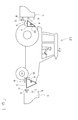
- FIG. 1 shows a designed as a tractor 2 carrier vehicle 1, which receives in its rear region in a conventional manner an agricultural implement 3, such as a plow, a haymaking machine or a mower.
- an agricultural working implement 3 can also be adapted to this in the front and / or side area of the agricultural carrier vehicle 1.
- the agricultural implement 3 can be received either by a so-called traction jaw 4 or the three-point hitch 5 of the tractor 2, wherein the agricultural carrier vehicle 1 depending on equipment level front and / or rear side can have a traction jaw 4 and a corresponding three-point hitch 5 ,
- the to be adapted to the carrier vehicle 1 implements 3 perform a variety of work functions, the necessary to carry out these work functions working elements of the implements 3 hydraulically and / or electrically and / or mechanically driven and the respectively required drive power supply lines 6-8 of the respective carrier vehicle 1 are provided.
- the transmission of mechanical drive energy can be effected by means of a coupling of a drive unit-side drive train 6 to the respective PTO shaft 9 of the carrier vehicle 1.
- Hydraulic drive energy is usually transmitted via hydraulic lines 8 between a carrier vehicle 1 and the work equipment 3 assigned to it.
- the carrier vehicle 1 has a first, in FIG. 1 only schematically shown, with the carrier vehicle 1 rotatably connected coupling part 10 which can be coupled to a working device 3 second, all hydraulic lines 8 of the implement 3 receiving coupling part 11, wherein the first and second coupling parts 10, 11 the to be explained in more detail below coupling 12 according to the invention for connecting hydraulic lines 8.
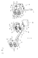
- FIG. 2 shows the coupling 12 according to the invention in the left-hand illustration in the closed and in the right-hand illustration in the open state.
- the first and second coupling parts 10, 11 are in the closed state with their inside flange surfaces 13, 14 directly to each other.
- the first coupling part 10 is associated with a locking device 15 according to the invention, which can be pivoted about a transversely to the coupling 12 extending pivot axis 16 by means of a hand lever 17 from a locking position 18 in an unlocking position 19.
- the locking device 15 comprises on both sides of the first coupling part 10 associated locking flanges 20 which are fastened by means of screw 21 on the pivot axis 16 of the locking device 15.
- one of the locking flanges 20 removably receives the hand lever 17.
- the first coupling part 10 removably receives a securing pin 22 which is at least partially form-fittingly engaged by it associated locking flange 20 is encompassed, so that when inserted locking pin 22, a rotation of the coupling parts 10, 11 against each other and thus opening of the clutch 20 is not possible.
- Each locking flange 20 is also on its coupling parts 10, 11 side facing in accordance with the invention a curved path 23 associated, which cooperates in a manner to be described in more detail with both sides of the second coupling part 11 associated locating pins 24.
- the second coupling part 11 in the region of its flange 14 one or more, associated in the illustrated embodiment, two positioning bolts 25 which engage during the coupling process of the two coupling parts 10, 11 in the first coupling part 10 penetrating receiving holes 26, so that the second coupling part 11 by means of this Retaining bolt 25 in a simple manner and accurately with the first coupling part 10 can be brought into operative connection.
- each coupling part 10, 11 has four hydraulic connections 27, wherein it is within the scope of the invention to provide any number of hydraulic connections 27 here.
- the hydraulic connections 27 of the second coupling part 11 can be connected to each other in a manner known per se via unspecified plug-in couplings 28 assigned to the first coupling part 10.
- the hydraulic connections 27 and the plug-in couplings 28 are positioned relative to one another in such a way that all the hydraulic lines 8 associated with the working device 3 are connected to the hydraulic circuit of the carrier vehicle 1 in a single coupling operation.
- the mutually coupled hydraulic connections 27 and their respective plug-in couplings 28 support the second coupling part 11 on the first coupling part 10.
- connection of the hose lines 8 to the hydraulic circuit of the carrier vehicle 1 is usually effected by the first coupling part 10 connected in a rotationally fixed manner to the carrier vehicle 1 being coupled to a valve block 29 assigned to the carrier vehicle 1, which regulates the pressurization and depressurization of the individual hydraulic lines 8 ,
- FIG. 3 now shows the coupling process of the first and second coupling part 10, 11 in detail.
- the second coupling part 11 according to FIG. 3a so brought to the first coupling part 10 that the second coupling part 11 associated positioning pins 25 engage in the corresponding receiving bores 26 of the first coupling part 10.
- the second coupling part 11 is brought so far to the first coupling part 10 that the fixing pins 24 of the second coupling part 11 abut against the respective locking flange 20 of the locking device 15.
- the fixing pin 24 assumes a position above the entry region 30 of the respective locking flange 20 associated, the inventive curved path 23 a.
- each curved path 23 and the guide channel 32 formed by it has a curvilinear guide region 33 beginning in the entry region 30 and a linear release region 34 adjoining this guide region 33.
- the hand lever 17 is moved in the direction of arrow 35 in the vertical direction, pivot the locking flanges 20 about its pivot axis 16 in an exemplary in FIG. 3b shown position in which the fixing pins 24 are moved by the curved guide portion 33 of the guide channel 32. Because of the U-shaped shape 31 of the guide channel 32, the fixing pin 24 can not leave the guide channel 32 during movement through the curved guide portion 33, so that during the coupling or unlocking of the clutch 12, the first and second coupling parts 10, 11 because of the positive guide in the guide channel 32 are forcibly moved toward or away from each other.
Abstract
Description
Die Erfindung betrifft eine Kupplung zum Verbinden von Hydraulikleitungen nach dem Oberbegriff des Anspruchs 1.The invention relates to a coupling for connecting hydraulic lines according to the preamble of claim 1.
Aus der
Wird eine Kupplungseinrichtung nach der
Es ist deshalb Aufgabe der Erfindung die beschriebenen Nachteile des Standes der Technik zu vermeiden und insbesondere eine Kupplung zum Verbinden von Hydraulikleitungen vorzuschlagen, die einerseits im normalen Arbeitsbetrieb eine sichere Verbindung der Hydraulikanschlüsse zwischen Trägerfahrzeug und adaptierten Gerät sicherstellt, andererseits aber auch beim Erreichen von unzulässigen Schlauchbelastungen ein Lösen der Schlauverbindungen ermöglicht.It is therefore an object of the invention to avoid the disadvantages of the prior art described and in particular to propose a coupling for connecting hydraulic lines, on the one hand ensures a secure connection of the hydraulic connections between the carrier vehicle and adapted device in normal operation, on the other hand, but also when reaching inadmissible hose loads a release of the smart connections allows.
Diese Aufgabe wird erfindungsgemäß durch die kennzeichnenden Merkmale des Anspruchs 1 gelöst.This object is achieved by the characterizing features of claim 1.
Indem die Kupplung zum Verbinden von Hydraulikleitungen ein erstes, mit dem Trägerfahrzeug verbundenes Kupplungsteil und ein mit dem ersten Kupplungsteil verbindbares zweites Kupplungsteil, eine dem ersten Kupplungsteil zugeordnete Arretiervorrichtung und zumindest einen dem zweiten Kupplungsteil zugeordneten, mit der Arretiervorrichtung in Eingriff bringbaren Fixierstift umfasst und der zumindest eine Fixierstift während der Kupplung des ersten und zweiten Kupplungsteils in einer der Arretiervorrichtung zugeordneten Kurvenbahn geführt und in der Arretierposition von dieser freigegeben wird, wird sichergestellt, dass die Kupplung beim Erreichen von unzulässigen Schlauchbelastungen ein Lösen der Schlauverbindungen ermöglicht und der Koppelvorgang zugleich schnell und präzise ausgeführt werden kann.In that the coupling for connecting hydraulic lines comprises a first coupling part connected to the carrier vehicle and a second coupling part connectable to the first coupling part, a locking device associated with the first coupling part and at least one fixing pin associated with the locking device and at least one fixing element which is associated with the second coupling part a fixing pin is guided during the coupling of the first and second coupling part in a locking device associated cam track and released in the locking position of this, it is ensured that the clutch when reaching inadmissible hose loads allows loosening the smart connections and executed the coupling process both fast and accurate can be.
In einer vorteilhaften Ausgestaltung der Erfindung wird das positionsgenaue Koppeln der Kupplungsteile auf konstruktiv einfache Weise gelöst, wenn dem zweiten Kupplungsteil ein oder mehrere Positionierbolzen zugeordnet sind, die mit Aufnahmebohrungen des ersten Kupplungsteils derart zusammenwirken, dass das das zweite Kupplungsteil mittels der Positionierbolzen in dem ersten Kupplungsteil geführt wird.In an advantageous embodiment of the invention, the positionally accurate coupling of the coupling parts is achieved in a structurally simple manner, if the second coupling part associated with one or more positioning, which cooperate with receiving bores of the first coupling part such that the second coupling part by means of positioning in the first coupling part to be led.
Indem schließlich die der Arretiervorrichtung zugeordnete Kurvenbahn einen kurvenförmigen Führungsbereich und einen linearen Freigabebereich umfasst, wird auf konstruktiv einfache Weise sichergestellt, dass der Koppelvorgang selbst optimal unterstützt wird und ohne weitere, vom Bediener durchzuführende Maßnahmen, die Arretierposition erreicht wird, die bei Überschreitung von Belastungsgrenzen automatisch die Kupplung öffnet.Finally, by virtue of the cam track associated with the locking device comprising a curved guide area and a linear release area, it is ensured in a structurally simple manner that the coupling process itself is optimally supported and, without further measures to be performed by the operator, the locking position is reached, which automatically exceeds this limit the clutch opens.
In einer vorteilhaften Ausgestaltung der Erfindung wird die sichere Führung des Fixierstift in der Kurvenbahn dann erreicht, wenn die Kurvenbahn als einseitig geöffnetes, einen Führungskanal bildendes U-Profil ausgestaltet ist.In an advantageous embodiment of the invention, the secure guidance of the fixing pin in the curved path is achieved when the curved path is configured as a unilaterally open, a guide channel forming U-profile.
Eine besonders einfache Handhabung der Kupplungsvorrichtung ergibt sich in einer weiteren vorteilhaften Ausgestaltung der Erfindung dann, wenn die Arretiervorrichtung zur Auslösung des Arretiervorganges und zum Lösen der ersten und zweiten Kupplungsteile mittels Handhebel von der Entriegelungsposition in die Arretierposition und umgekehrt verschwenkbar ist.A particularly simple handling of the coupling device results in a further advantageous embodiment of the invention, when the locking device for triggering the locking operation and for releasing the first and second coupling parts by means of hand lever from the unlocking position in the locking position and vice versa is pivoted.
In einer vorteilhaften Weiterbildung der Erfindung umfasst die Arretiervorrichtung erste und zweite Verriegelungsflansche, wobei jeder Verriegelungsflansch eine Kurvenbahn aufnimmt und einem Seitenbereich des ersten Kupplungsteils drehbar zugeordnet ist und jeweils mit einem den Seitenbereichen des zweiten Kupplungsteils zugeordneten Fixierstift in Wirkverbindung bringbar ist. Eine derartige Ausgestaltung hat vor allem den Vorteil, dass eine kompakte, wenig Bauraum benötigenden Kupplung geschaffen wird, die in einen nur begrenzt zur Verfügung stehenden Bauraum optimal integrierbar ist.In an advantageous development of the invention, the locking device comprises first and second locking flanges, wherein each locking flange receives a cam track and is rotatably associated with a side portion of the first coupling part and in each case engageable with a side portions of the second coupling part fixing pin in operative connection. Such an embodiment has the particular advantage that a compact, little space-requiring coupling is provided, which is optimally integrated in a limited space available.
Eine hohe Flexibilität bezüglich der Art der mittels der erfindungsgemäßen Kupplung an ein Trägerfahrzeug adaptierbaren Arbeitsgeräte ergibt sich dann, wenn die ersten und zweiten Kupplungsteile eine Vielzahl von Schlauchleitungen aufnehmen können.A high degree of flexibility with regard to the type of working devices which can be adapted to a carrier vehicle by means of the coupling according to the invention results when the first and second coupling parts can accommodate a large number of hose lines.
Eine sichere und konstruktiv einfach ausgeführte Abstützung des zweiten Kupplungsteils an dem ersten Kupplungsteil wird dann erreicht, wenn die Schlauchleitungen über Hydraulikanschlüsse mit dem zweiten Kupplungsteil verbundnen sind und diese Hydraulikanschlüsse mit den dem ersten Kupplungsteil zugeordneten Steckkupplungen gekoppelt werden.A safe and structurally simple running support of the second coupling part on the first coupling part is then achieved when the hose lines via hydraulic connections with the second coupling part are connected and these hydraulic connections are coupled to the first coupling part associated plug-in couplings.
Damit zudem sichergestellt ist, dass die einzelnen Schlauchleitungen nicht separat von der Kupplung getrennt werden ist in einer vorteilhaften Ausgestaltung der Erfindung vorgesehen, dass die Haltekraft jeder Schlauchkupplung so dimensioniert ist, dass sie größer als die Lösekraft des zweiten Kupplungsteils vom ersten Kupplungsteil ist.So that it is also ensured that the individual hose lines are not separated separately from the coupling is provided in an advantageous embodiment of the invention that the holding force of each hose coupling is dimensioned so that it is greater than the release force of the second coupling part of the first coupling part.
Damit beispielsweise bei Straßenfahrt und im Arbeitsbetrieb des Trägerfahrzeugs mit adaptierten Arbeitsgerät sichergestellt ist, dass sich die Kupplung nicht durch fahrgeschwindigkeits-bedingte Stoßbelastungen öffnet ist in einer weiteren vorteilhaften Ausgestaltung der Erfindung vorgesehen, dass zumindest einem der Verriegelungsflansche der Arretiervorrichtung in der Arretierposition ein Sicherungsstift zugeordnet ist.Thus, for example, when driving on the road and during operation of the carrier vehicle with adapted implement ensures that the clutch does not open by driving speed-related shock loads is provided in a further advantageous embodiment of the invention that at least one of the locking flanges of the locking device in the locking position is assigned a locking pin ,
Damit die Kupplung mit wenigen Handgriffen händisch entriegelbar ist, ist in einer weiteren vorteilhaften Ausgestaltung der Erfindung vorgesehen, dass der Sicherungsstift entfernbar an der Kupplung angeordnet ist.Thus, the clutch can be unlocked manually with a few simple steps, it is provided in a further advantageous embodiment of the invention that the locking pin is removably mounted on the clutch.
Das Einsatzspektrum der erfindungsgemäßen Kupplung kann dadurch beträchtlich erhöht werden, wenn das Trägerfahrzeug als land- oder forstwirtschaftliches Trägerfahrzeug, vorzugsweise Traktor, ausgeführt ist und das zweite Kupplungsteil einem mit dem land- oder forstwirtschaftlichen Trägerfahrzeug koppelbaren Arbeitsgerät zugeordnet ist. Dieser Effekt ergibt sich in analoger Weise, wenn das Trägerfahrzeug als Baumaschine ausgeführt und das zweite Kupplungsteil einem mit der Baumaschine koppelbaren Arbeitsgerät zugeordnet ist.The range of applications of the coupling according to the invention can be considerably increased, if the carrier vehicle is designed as agricultural or forestry carrier vehicle, preferably tractor, and the second coupling part is associated with a connectable to the agricultural or forestry carrier vehicle implement. This effect results in an analogous manner when the carrier vehicle is designed as a construction machine and the second coupling part is associated with a work implement which can be coupled to the construction machine.
Weitere vorteilhafte Ausgestaltungen sind Gegenstand weiterer Unteransprüche und werden nachfolgend an Hand in mehreren Figuren dargestellter Ausführungsbeispiele beschrieben. Es zeigen:
- Figur 1
- ein als Traktor ausgeführtes und die erfindungsgemäße Kupplung umfassendes Trägerfahrzeug
- Figur 2
- eine schematische Detailansicht der Erfindungsgemäßen Kupplung
Figur 3- eine schematische Darstellung des erfindungsgemäßen Kuppelvorgangs
- FIG. 1
- a running as a tractor and the inventive clutch comprehensive carrier vehicle
- FIG. 2
- a schematic detail view of the inventive coupling
- FIG. 3
- a schematic representation of the coupling process according to the invention
In dem dargestellten Ausführungsbeispiel verfügt jedes Kupplungsteil 10, 11 über vier Hydraulikanschlüsse 27, wobei es im Rahmen der Erfindung liegt, hier eine beliebige Anzahl von Hydraulikanschlüssen 27 vorzusehen. Die Hydraulikanschlüsse 27 des zweiten Kupplungsteils 11 sind in an sich bekannter Weise über nicht näher beschriebene, dem ersten Kupplungsteil 10 zugeordnete Steckkupplungen 28 miteinander verbindbar. Die Hydraulikanschlüsse 27 sowie die Steckkupplungen 28 sind dabei so zueinander positioniert, dass in einem einzigen Kuppelvorgang alle dem Arbeitsgerät 3 zugeordneten Hydraulikleitungen 8 mit dem Hydraulikkreislauf des Trägerfahrzeugs 1 verbunden werden. Zugleich stützen die miteinander gekoppelten Hydraulikanschlüsse 27 und ihnen jeweils zugeordneten Steckkupplungen 28 das zweite Kupplungsteil 11 an dem ersten Kupplungsteil 10 ab. Die Verbindung der Schlauchleitungen 8 mit dem Hydraulikkreislauf des Trägerfahrzeugs 1 wird in der Regel dadurch bewirkt, dass das mit dem Trägerfahrzeug 1 drehfest verbundene erste Kupplungsteil 10 mit einem dem Trägerfahrzeug 1 zugeordneten Ventilblock 29 gekoppelt ist, der die Druckbeaufschlagung und Druckentlastung der einzelnen Hydraulikleitungen 8 regelt.In the illustrated embodiment, each
Indem nun der Handhebel 17 gemäß Pfeilrichtung 35 in vertikaler Richtung bewegt wird, schwenken die Verriegelungsflansche 20 um ihre Schwenkachse 16 in eine beispielhaft in
Indem der Handhebel 17 weiter gemäß Pfeilrichtung 35 in vertikaler Richtung verschwenkt wird gelangt er schließlich in die in
Zur Öffnung der Kupplung 12 wird schließlich der Handhebel 17 gemäß der in
In einer vorteilhaften Ausgestaltung der Erfindung können die in
Claims (13)
dadurch gekennzeichnet,
dass der zumindest eine Fixierstift (24) während der Kupplung des ersten und zweiten Kupplungsteils (10, 11) in einer der Arretiervorrichtung (15) zugeordneten Kurvenbahn (23) geführt und in der Arretierposition (18) von dieser freigegeben wird.Coupling for connecting hydraulic lines to a first coupling part connected to the carrier vehicle and a second coupling part connectable to the first coupling part, a locking device associated with the first coupling part and at least one fixing pin which is associated with the locking device and assigned to the second coupling part,
characterized,
in that the at least one fixing pin (24) is guided during the coupling of the first and second coupling parts (10, 11) in a cam track (23) assigned to the locking device (15) and released in the locking position (18).
dadurch gekennzeichnet,
dass dem zweiten Kupplungsteil (11) ein oder mehrere Positionierbolzen (25) zugeordnet sind, die mit Aufnahmebohrungen (26) des ersten Kupplungsteils (10) derart zusammenwirken, dass das erste Kupplungsteil 10 und das zweite Kupplungsteil (11) positionsgenau miteinander gekoppelt werden können.Coupling for connecting hydraulic lines according to claim 1,
characterized,
in that one or more positioning bolts (25) are associated with the second coupling part (11), which cooperate with receiving bores (26) of the first coupling part (10) in such a way that the first coupling part 10 and the second coupling part (11) can be coupled to each other in a positionally accurate manner.
dadurch gekennzeichnet,
dass die der Arretiervorrichtung (15) zugeordnete Kurvenbahn (23) einen kurvenförmigen Führungsbereich (33) und einen linearen Freigabebereich (34) umfasst.Coupling for connecting hydraulic lines according to one of the preceding claims,
characterized,
in that the cam track (23) associated with the locking device (15) comprises a curved guide area (33) and a linear release area (34).
dadurch gekennzeichnet,
dass die Kurvenbahn (23) als einseitig geöffnetes, einen Führungskanal (32) bildendes U-Profil (31) ausgestaltet ist.Coupling for connecting hydraulic lines according to claim 3,
characterized,
that the curved track (23) forming a unilaterally open, a guide channel (32) U-profile (31) is arranged.
dadurch gekennzeichnet,
dass die Arretiervorrichtung (15) zur Auslösung des Arretiervorganges und zum Lösen der ersten und zweiten Kupplungsteile (10, 11) mittels Handhebel (17) von der Entriegelungsposition (19) in die Arretierposition (18) und umgekehrt verschwenkbar ist.Coupling for connecting hydraulic lines according to one of the preceding claims,
characterized,
that the locking device (15) for triggering the locking operation and for releasing the first and second coupling parts (10, 11) by means of hand lever (17) from the unlocking position (19) in the locking position (18) and vice versa is pivotable.
dadurch gekennzeichnet,
dass die Arretiervorrichtung (15) erste und zweite Verriegelungsflansche (20) umfasst und jeder Verriegelungsflansch (20) eine Kurvenbahn (23) aufnimmt, wobei jeder Verriegelungsflansch (20) einem Seitenbereich des ersten Kupplungsteils (10) drehbar zugeordnet ist und jeweils mit einem den Seitenbereichen des zweiten Kupplungsteils (11) zugeordneten Fixierstift (24) in Wirkverbindung bringbar ist.Coupling for connecting hydraulic lines according to one of the preceding claims,
characterized,
in that the locking device (15) comprises first and second locking flanges (20) and each locking flange (20) receives a cam track (23), each locking flange (20) being rotatably associated with a side portion of the first coupling part (10) and each with one of the side portions the second coupling part (11) associated fixing pin (24) can be brought into operative connection.
dadurch gekennzeichnet,
dass die ersten und zweiten Kupplungsteile (10, 11) eine Vielzahl von Schlauchleitungen (8) aufnehmen.Coupling for connecting hydraulic lines according to one of the preceding claims,
characterized,
in that the first and second coupling parts (10, 11) receive a multiplicity of hose lines (8).
dadurch gekennzeichnet,
dass die Schlauchleitungen (8) über Hydraulikanschlüsse (27) mit dem zweiten Kupplungsteil (11) verbundnen sind und diese Hydraulikanschlüsse (27) mit den dem ersten Kupplungsteil (10) zugeordneten Steckkupplungen (28) gekoppelt werden.Coupling for connecting hydraulic lines according to claim 7,
characterized,
in that the hose lines (8) are connected to the second coupling part (11) via hydraulic connections (27) and these hydraulic connections (27) are coupled to the plug-in connections (28) associated with the first coupling part (10).
dadurch gekennzeichnet,
dass die Haltekraft (F2) jeder der den Hydraulikleitungen (8) zugeordneten Steckkupplungen (28) so dimensioniert ist, dass sie größer als die Lösekraft (F1) des zweiten Kupplungsteils (11) vom ersten Kupplungsteil (10) ist.Coupling for connecting hydraulic lines according to one of the preceding claims,
characterized,
that the holding force (F2) of each of the associated hydraulic lines (8), plug-in couplings (28) is dimensioned so that it is greater than the release force (F1) of the second coupling part (11) of the first coupling part (10).
dadurch gekennzeichnet,
dass zumindest einem der Verriegelungsflansche (20) der Arretiervorrichtung (15) in der Arretierposition (18) ein Sicherungsstift (22) zugeordnet ist.Coupling for connecting hydraulic lines according to one of the preceding claims,
characterized,
in that at least one of the locking flanges (20) of the locking device (15) is assigned a securing pin (22) in the locking position (18).
dadurch gekennzeichnet,
dass der Sicherungsstift (22) entfernbar ist.Coupling for connecting hydraulic lines according to claim 10,
characterized,
that the locking pin (22) is removable.
dadurch gekennzeichnet,
dass das Trägerfahrzeug (1) als land- oder forstwirtschaftliches Trägerfahrzeug, vorzugsweise Traktor (2), ausgeführt ist und das zweite Kupplungsteil (11) einem mit dem land- oder forstwirtschaftlichen Trägerfahrzeug (1) koppelbaren Arbeitsgerät (3) zugeordnet ist.Coupling for connecting hydraulic lines according to one of the preceding claims,
characterized,
in that the carrier vehicle (1) is designed as a agricultural or forestry carrier vehicle, preferably a tractor (2), and the second coupling part (11) is assigned to a working device (3) which can be coupled to the agricultural or forestry carrier vehicle (1).
dadurch gekennzeichnet,
dass das Trägerfahrzeug (1) als Baumaschine ausgeführt ist und das zweite Kupplungsteil (11) einem mit der Baumaschine koppelbaren Arbeitsgerät (3) zugeordnet ist.Coupling for connecting hydraulic lines according to one of the claims 1-12,
characterized,
in that the carrier vehicle (1) is designed as a construction machine and the second coupling part (11) is assigned to a working device (3) which can be coupled to the construction machine.
Applications Claiming Priority (1)
| Application Number | Priority Date | Filing Date | Title |
|---|---|---|---|
| DE102009056071A DE102009056071A1 (en) | 2009-11-30 | 2009-11-30 | Coupling for connecting hydraulic lines, has coupling part connected with carrier vehicle and another coupling part connected with former coupling part |
Publications (2)
| Publication Number | Publication Date |
|---|---|
| EP2399441A1 true EP2399441A1 (en) | 2011-12-28 |
| EP2399441B1 EP2399441B1 (en) | 2016-04-13 |
Family
ID=43972069
Family Applications (1)
| Application Number | Title | Priority Date | Filing Date |
|---|---|---|---|
| EP10174504.0A Active EP2399441B1 (en) | 2009-11-30 | 2010-08-30 | Coupling for combining hydraulic lines |
Country Status (3)
| Country | Link |
|---|---|
| EP (1) | EP2399441B1 (en) |
| DE (1) | DE102009056071A1 (en) |
| RU (1) | RU2540102C2 (en) |
Cited By (5)
| Publication number | Priority date | Publication date | Assignee | Title |
|---|---|---|---|---|
| US20170202128A1 (en) * | 2016-01-19 | 2017-07-20 | Deere & Company | Work vehicle multi-coupler with breakaway feature |
| CN109578733A (en) * | 2017-09-28 | 2019-04-05 | 法斯特股份公司 | Hydraulic and/or pneumatic connector |
| USD868948S1 (en) | 2018-02-09 | 2019-12-03 | Cnh Industrial America Llc | Hydraulic multi-coupler having an optional port |
| USD869615S1 (en) | 2018-02-09 | 2019-12-10 | Cnh Industrial America Llc | Hydraulic multi-coupler having an interference tab |
| US10806066B2 (en) | 2018-05-18 | 2020-10-20 | Deere & Company | Implement multi-coupler with breakaway feature |
Families Citing this family (4)
| Publication number | Priority date | Publication date | Assignee | Title |
|---|---|---|---|---|
| DE202011051870U1 (en) * | 2011-11-04 | 2011-11-18 | Feldbinder Spezialfahrzeugwerke Gmbh | Coupling device for a semi-trailer |
| AT514147B1 (en) * | 2013-03-25 | 2016-01-15 | Scharmüller Josef Ing | coupling part |
| DE102017126477A1 (en) | 2017-11-10 | 2019-05-16 | Syn Trac Gmbh | clutch plate |
| DE102022126522A1 (en) | 2022-10-12 | 2024-04-18 | Liebherr-France Sas | Working machine with coupling device for fluid-carrying lines |
Citations (6)
| Publication number | Priority date | Publication date | Assignee | Title |
|---|---|---|---|---|
| FR1411596A (en) * | 1964-10-14 | 1965-09-17 | Quick coupling for pipes | |
| FR2645242A1 (en) * | 1989-03-29 | 1990-10-05 | Etud Innovation Mat Agricole | MULTIPLE FLUID CONNECTOR |
| DE9209060U1 (en) * | 1991-07-09 | 1992-10-22 | Faster S.R.L., Melzo, Mailand/Milano, It | |
| DE4412115A1 (en) | 1994-04-08 | 1995-10-12 | Deere & Co | Device for connecting equipment to a machine, in particular a header to a harvester |
| FR2745043A1 (en) * | 1996-02-16 | 1997-08-22 | Alo Maskiner Ab | Ganged hydraulic connector for loader bucket |
| WO2004031637A1 (en) * | 2002-10-01 | 2004-04-15 | Josef Martin Gmbh & Co. Kg | Multicoupling device |
Family Cites Families (3)
| Publication number | Priority date | Publication date | Assignee | Title |
|---|---|---|---|---|
| US2333423A (en) * | 1941-09-29 | 1943-11-02 | Thompson Prod Inc | Quick disconnect coupling |
| EP0522493B2 (en) * | 1991-07-09 | 2001-10-24 | FASTER S.r.l. | Quick acting coupling for the simultaneous make-up and release of the connection for several couplings and/or plugs, in particular coupling-manifold for tool front connector on vehicles |
| DE202006005203U1 (en) * | 2006-03-31 | 2007-08-09 | Liebherr-Hydraulikbagger Gmbh | quick coupling |
-
2009
- 2009-11-30 DE DE102009056071A patent/DE102009056071A1/en not_active Withdrawn
-
2010
- 2010-08-30 EP EP10174504.0A patent/EP2399441B1/en active Active
- 2010-11-29 RU RU2010148413/13A patent/RU2540102C2/en active
Patent Citations (6)
| Publication number | Priority date | Publication date | Assignee | Title |
|---|---|---|---|---|
| FR1411596A (en) * | 1964-10-14 | 1965-09-17 | Quick coupling for pipes | |
| FR2645242A1 (en) * | 1989-03-29 | 1990-10-05 | Etud Innovation Mat Agricole | MULTIPLE FLUID CONNECTOR |
| DE9209060U1 (en) * | 1991-07-09 | 1992-10-22 | Faster S.R.L., Melzo, Mailand/Milano, It | |
| DE4412115A1 (en) | 1994-04-08 | 1995-10-12 | Deere & Co | Device for connecting equipment to a machine, in particular a header to a harvester |
| FR2745043A1 (en) * | 1996-02-16 | 1997-08-22 | Alo Maskiner Ab | Ganged hydraulic connector for loader bucket |
| WO2004031637A1 (en) * | 2002-10-01 | 2004-04-15 | Josef Martin Gmbh & Co. Kg | Multicoupling device |
Cited By (9)
| Publication number | Priority date | Publication date | Assignee | Title |
|---|---|---|---|---|
| US20170202128A1 (en) * | 2016-01-19 | 2017-07-20 | Deere & Company | Work vehicle multi-coupler with breakaway feature |
| CN107006157A (en) * | 2016-01-19 | 2017-08-04 | 迪尔公司 | The many connectors of working truck with detaching structure |
| US9968021B2 (en) * | 2016-01-19 | 2018-05-15 | Deere & Company | Work vehicle multi-coupler with breakaway feature |
| CN107006157B (en) * | 2016-01-19 | 2022-03-18 | 迪尔公司 | Work vehicle multi-coupler with disengagement feature |
| CN109578733A (en) * | 2017-09-28 | 2019-04-05 | 法斯特股份公司 | Hydraulic and/or pneumatic connector |
| CN109578733B (en) * | 2017-09-28 | 2022-04-01 | 法斯特有限责任公司 | Hydraulic and/or pneumatic connector |
| USD868948S1 (en) | 2018-02-09 | 2019-12-03 | Cnh Industrial America Llc | Hydraulic multi-coupler having an optional port |
| USD869615S1 (en) | 2018-02-09 | 2019-12-10 | Cnh Industrial America Llc | Hydraulic multi-coupler having an interference tab |
| US10806066B2 (en) | 2018-05-18 | 2020-10-20 | Deere & Company | Implement multi-coupler with breakaway feature |
Also Published As
| Publication number | Publication date |
|---|---|
| DE102009056071A1 (en) | 2011-06-09 |
| EP2399441B1 (en) | 2016-04-13 |
| RU2540102C2 (en) | 2015-02-10 |
| RU2010148413A (en) | 2012-06-10 |
Similar Documents
| Publication | Publication Date | Title |
|---|---|---|
| EP2399441B1 (en) | Coupling for combining hydraulic lines | |
| EP1346625B1 (en) | Device for attaching a header to a combine | |
| DE4412115B4 (en) | drive connection | |
| DE102017200743A1 (en) | Working vehicle multiple clutch arrangement | |
| DE4132889C2 (en) | ||
| EP3706529B1 (en) | Docking apparatus having a docking receptacle and a docking insert, and method for coupling a vehicle | |
| DE10153823C1 (en) | Coupling aid for connecting up trailer to tractor includes rail connecting with lower rods of tractor and supporting guide means which align shaft with relative movement in longitudinal direction | |
| EP2978299B1 (en) | Coupling part | |
| DE102019205528A1 (en) | MULTI COUPLING FOR WORKING DEVICES WITH TEARING FUNCTION | |
| EP3390122B1 (en) | Hitching device with automatically connectable supply plug components | |
| DE4412116C2 (en) | Removable harvesting attachment | |
| DE102017126505A1 (en) | Hydraulic system for a vehicle and a vehicle with such a hydraulic system | |
| DE102011052434B4 (en) | trailer hitch | |
| BE1022180B1 (en) | DEVICE AND METHOD FOR MOUNTING A HARVESTING EQUIPMENT TO A MINING MACHINE | |
| DE102014002376B3 (en) | Automatic clutch system and vehicle with such a clutch system | |
| DE102019118836B4 (en) | Adapter arrangement for a tractor trailer arrangement | |
| EP2820932B1 (en) | Trailer coupling | |
| EP2820933B1 (en) | Working vehicle with a trailer coupling mounted at its rear | |
| WO2019092207A1 (en) | Vehicle-side and accessory-side power take-off shaft connecting device and power take-off shaft connecting unit comprising the two power take-off shaft connecting devices | |
| EP2801246B1 (en) | Agricultural attachment or trailer device | |
| EP3706530B1 (en) | Drive shaft connecting unit | |
| AT229722B (en) | Attachment gearbox that can be connected to a tractor PTO shaft | |
| EP4342272A1 (en) | Drawbar and working tool | |
| DE2241434A1 (en) | DEVICE FOR COUPLING A VEHICLE WITH A DEVICE, TRAILER OD. THE LIKE, IN PARTICULAR A TRACTOR WITH AN AGRICULTURAL MACHINE OR TRAILER |
Legal Events
| Date | Code | Title | Description |
|---|---|---|---|
| AK | Designated contracting states |
Kind code of ref document: A1 Designated state(s): AL AT BE BG CH CY CZ DE DK EE ES FI FR GB GR HR HU IE IS IT LI LT LU LV MC MK MT NL NO PL PT RO SE SI SK SM TR |
|
| AX | Request for extension of the european patent |
Extension state: BA ME RS |
|
| PUAI | Public reference made under article 153(3) epc to a published international application that has entered the european phase |
Free format text: ORIGINAL CODE: 0009012 |
|
| 17P | Request for examination filed |
Effective date: 20120628 |
|
| GRAP | Despatch of communication of intention to grant a patent |
Free format text: ORIGINAL CODE: EPIDOSNIGR1 |
|
| INTG | Intention to grant announced |
Effective date: 20151214 |
|
| GRAS | Grant fee paid |
Free format text: ORIGINAL CODE: EPIDOSNIGR3 |
|
| GRAA | (expected) grant |
Free format text: ORIGINAL CODE: 0009210 |
|
| AK | Designated contracting states |
Kind code of ref document: B1 Designated state(s): AL AT BE BG CH CY CZ DE DK EE ES FI FR GB GR HR HU IE IS IT LI LT LU LV MC MK MT NL NO PL PT RO SE SI SK SM TR |
|
| REG | Reference to a national code |
Ref country code: GB Ref legal event code: FG4D Free format text: NOT ENGLISH |
|
| REG | Reference to a national code |
Ref country code: AT Ref legal event code: REF Ref document number: 789024 Country of ref document: AT Kind code of ref document: T Effective date: 20160415 Ref country code: CH Ref legal event code: EP |
|
| REG | Reference to a national code |
Ref country code: IE Ref legal event code: FG4D Free format text: LANGUAGE OF EP DOCUMENT: GERMAN |
|
| REG | Reference to a national code |
Ref country code: DE Ref legal event code: R096 Ref document number: 502010011418 Country of ref document: DE |
|
| REG | Reference to a national code |
Ref country code: LT Ref legal event code: MG4D |
|
| REG | Reference to a national code |
Ref country code: NL Ref legal event code: MP Effective date: 20160413 |
|
| PG25 | Lapsed in a contracting state [announced via postgrant information from national office to epo] |
Ref country code: FI Free format text: LAPSE BECAUSE OF FAILURE TO SUBMIT A TRANSLATION OF THE DESCRIPTION OR TO PAY THE FEE WITHIN THE PRESCRIBED TIME-LIMIT Effective date: 20160413 Ref country code: NL Free format text: LAPSE BECAUSE OF FAILURE TO SUBMIT A TRANSLATION OF THE DESCRIPTION OR TO PAY THE FEE WITHIN THE PRESCRIBED TIME-LIMIT Effective date: 20160413 Ref country code: PL Free format text: LAPSE BECAUSE OF FAILURE TO SUBMIT A TRANSLATION OF THE DESCRIPTION OR TO PAY THE FEE WITHIN THE PRESCRIBED TIME-LIMIT Effective date: 20160413 Ref country code: NO Free format text: LAPSE BECAUSE OF FAILURE TO SUBMIT A TRANSLATION OF THE DESCRIPTION OR TO PAY THE FEE WITHIN THE PRESCRIBED TIME-LIMIT Effective date: 20160713 Ref country code: LT Free format text: LAPSE BECAUSE OF FAILURE TO SUBMIT A TRANSLATION OF THE DESCRIPTION OR TO PAY THE FEE WITHIN THE PRESCRIBED TIME-LIMIT Effective date: 20160413 |
|
| PG25 | Lapsed in a contracting state [announced via postgrant information from national office to epo] |
Ref country code: LV Free format text: LAPSE BECAUSE OF FAILURE TO SUBMIT A TRANSLATION OF THE DESCRIPTION OR TO PAY THE FEE WITHIN THE PRESCRIBED TIME-LIMIT Effective date: 20160413 Ref country code: ES Free format text: LAPSE BECAUSE OF FAILURE TO SUBMIT A TRANSLATION OF THE DESCRIPTION OR TO PAY THE FEE WITHIN THE PRESCRIBED TIME-LIMIT Effective date: 20160413 Ref country code: HR Free format text: LAPSE BECAUSE OF FAILURE TO SUBMIT A TRANSLATION OF THE DESCRIPTION OR TO PAY THE FEE WITHIN THE PRESCRIBED TIME-LIMIT Effective date: 20160413 Ref country code: SE Free format text: LAPSE BECAUSE OF FAILURE TO SUBMIT A TRANSLATION OF THE DESCRIPTION OR TO PAY THE FEE WITHIN THE PRESCRIBED TIME-LIMIT Effective date: 20160413 Ref country code: PT Free format text: LAPSE BECAUSE OF FAILURE TO SUBMIT A TRANSLATION OF THE DESCRIPTION OR TO PAY THE FEE WITHIN THE PRESCRIBED TIME-LIMIT Effective date: 20160816 Ref country code: GR Free format text: LAPSE BECAUSE OF FAILURE TO SUBMIT A TRANSLATION OF THE DESCRIPTION OR TO PAY THE FEE WITHIN THE PRESCRIBED TIME-LIMIT Effective date: 20160714 |
|
| PG25 | Lapsed in a contracting state [announced via postgrant information from national office to epo] |
Ref country code: BE Free format text: LAPSE BECAUSE OF NON-PAYMENT OF DUE FEES Effective date: 20160831 Ref country code: IT Free format text: LAPSE BECAUSE OF FAILURE TO SUBMIT A TRANSLATION OF THE DESCRIPTION OR TO PAY THE FEE WITHIN THE PRESCRIBED TIME-LIMIT Effective date: 20160413 |
|
| REG | Reference to a national code |
Ref country code: DE Ref legal event code: R097 Ref document number: 502010011418 Country of ref document: DE |
|
| PG25 | Lapsed in a contracting state [announced via postgrant information from national office to epo] |
Ref country code: SK Free format text: LAPSE BECAUSE OF FAILURE TO SUBMIT A TRANSLATION OF THE DESCRIPTION OR TO PAY THE FEE WITHIN THE PRESCRIBED TIME-LIMIT Effective date: 20160413 Ref country code: CZ Free format text: LAPSE BECAUSE OF FAILURE TO SUBMIT A TRANSLATION OF THE DESCRIPTION OR TO PAY THE FEE WITHIN THE PRESCRIBED TIME-LIMIT Effective date: 20160413 Ref country code: EE Free format text: LAPSE BECAUSE OF FAILURE TO SUBMIT A TRANSLATION OF THE DESCRIPTION OR TO PAY THE FEE WITHIN THE PRESCRIBED TIME-LIMIT Effective date: 20160413 Ref country code: RO Free format text: LAPSE BECAUSE OF FAILURE TO SUBMIT A TRANSLATION OF THE DESCRIPTION OR TO PAY THE FEE WITHIN THE PRESCRIBED TIME-LIMIT Effective date: 20160413 Ref country code: DK Free format text: LAPSE BECAUSE OF FAILURE TO SUBMIT A TRANSLATION OF THE DESCRIPTION OR TO PAY THE FEE WITHIN THE PRESCRIBED TIME-LIMIT Effective date: 20160413 |
|
| PLBE | No opposition filed within time limit |
Free format text: ORIGINAL CODE: 0009261 |
|
| STAA | Information on the status of an ep patent application or granted ep patent |
Free format text: STATUS: NO OPPOSITION FILED WITHIN TIME LIMIT |
|
| PG25 | Lapsed in a contracting state [announced via postgrant information from national office to epo] |
Ref country code: SM Free format text: LAPSE BECAUSE OF FAILURE TO SUBMIT A TRANSLATION OF THE DESCRIPTION OR TO PAY THE FEE WITHIN THE PRESCRIBED TIME-LIMIT Effective date: 20160413 |
|
| 26N | No opposition filed |
Effective date: 20170116 |
|
| PG25 | Lapsed in a contracting state [announced via postgrant information from national office to epo] |
Ref country code: MC Free format text: LAPSE BECAUSE OF FAILURE TO SUBMIT A TRANSLATION OF THE DESCRIPTION OR TO PAY THE FEE WITHIN THE PRESCRIBED TIME-LIMIT Effective date: 20160413 |
|
| REG | Reference to a national code |
Ref country code: CH Ref legal event code: PL |
|
| GBPC | Gb: european patent ceased through non-payment of renewal fee |
Effective date: 20160830 |
|
| PG25 | Lapsed in a contracting state [announced via postgrant information from national office to epo] |
Ref country code: CH Free format text: LAPSE BECAUSE OF NON-PAYMENT OF DUE FEES Effective date: 20160831 Ref country code: LI Free format text: LAPSE BECAUSE OF NON-PAYMENT OF DUE FEES Effective date: 20160831 |
|
| REG | Reference to a national code |
Ref country code: FR Ref legal event code: ST Effective date: 20170428 |
|
| PG25 | Lapsed in a contracting state [announced via postgrant information from national office to epo] |
Ref country code: SI Free format text: LAPSE BECAUSE OF FAILURE TO SUBMIT A TRANSLATION OF THE DESCRIPTION OR TO PAY THE FEE WITHIN THE PRESCRIBED TIME-LIMIT Effective date: 20160413 |
|
| REG | Reference to a national code |
Ref country code: IE Ref legal event code: MM4A |
|
| PG25 | Lapsed in a contracting state [announced via postgrant information from national office to epo] |
Ref country code: IE Free format text: LAPSE BECAUSE OF NON-PAYMENT OF DUE FEES Effective date: 20160830 Ref country code: FR Free format text: LAPSE BECAUSE OF NON-PAYMENT OF DUE FEES Effective date: 20160831 Ref country code: GB Free format text: LAPSE BECAUSE OF NON-PAYMENT OF DUE FEES Effective date: 20160830 |
|
| PG25 | Lapsed in a contracting state [announced via postgrant information from national office to epo] |
Ref country code: LU Free format text: LAPSE BECAUSE OF NON-PAYMENT OF DUE FEES Effective date: 20160830 |
|
| REG | Reference to a national code |
Ref country code: AT Ref legal event code: MM01 Ref document number: 789024 Country of ref document: AT Kind code of ref document: T Effective date: 20160830 |
|
| PG25 | Lapsed in a contracting state [announced via postgrant information from national office to epo] |
Ref country code: AT Free format text: LAPSE BECAUSE OF NON-PAYMENT OF DUE FEES Effective date: 20160830 |
|
| PG25 | Lapsed in a contracting state [announced via postgrant information from national office to epo] |
Ref country code: HU Free format text: LAPSE BECAUSE OF FAILURE TO SUBMIT A TRANSLATION OF THE DESCRIPTION OR TO PAY THE FEE WITHIN THE PRESCRIBED TIME-LIMIT; INVALID AB INITIO Effective date: 20100830 Ref country code: CY Free format text: LAPSE BECAUSE OF FAILURE TO SUBMIT A TRANSLATION OF THE DESCRIPTION OR TO PAY THE FEE WITHIN THE PRESCRIBED TIME-LIMIT Effective date: 20160413 |
|
| PG25 | Lapsed in a contracting state [announced via postgrant information from national office to epo] |
Ref country code: MT Free format text: LAPSE BECAUSE OF FAILURE TO SUBMIT A TRANSLATION OF THE DESCRIPTION OR TO PAY THE FEE WITHIN THE PRESCRIBED TIME-LIMIT Effective date: 20160413 Ref country code: IS Free format text: LAPSE BECAUSE OF FAILURE TO SUBMIT A TRANSLATION OF THE DESCRIPTION OR TO PAY THE FEE WITHIN THE PRESCRIBED TIME-LIMIT Effective date: 20160413 Ref country code: MK Free format text: LAPSE BECAUSE OF FAILURE TO SUBMIT A TRANSLATION OF THE DESCRIPTION OR TO PAY THE FEE WITHIN THE PRESCRIBED TIME-LIMIT Effective date: 20160413 Ref country code: TR Free format text: LAPSE BECAUSE OF FAILURE TO SUBMIT A TRANSLATION OF THE DESCRIPTION OR TO PAY THE FEE WITHIN THE PRESCRIBED TIME-LIMIT Effective date: 20160413 |
|
| PG25 | Lapsed in a contracting state [announced via postgrant information from national office to epo] |
Ref country code: BG Free format text: LAPSE BECAUSE OF FAILURE TO SUBMIT A TRANSLATION OF THE DESCRIPTION OR TO PAY THE FEE WITHIN THE PRESCRIBED TIME-LIMIT Effective date: 20160413 |
|
| PG25 | Lapsed in a contracting state [announced via postgrant information from national office to epo] |
Ref country code: AL Free format text: LAPSE BECAUSE OF FAILURE TO SUBMIT A TRANSLATION OF THE DESCRIPTION OR TO PAY THE FEE WITHIN THE PRESCRIBED TIME-LIMIT Effective date: 20160413 |
|
| P01 | Opt-out of the competence of the unified patent court (upc) registered |
Effective date: 20230515 |
|
| PGFP | Annual fee paid to national office [announced via postgrant information from national office to epo] |
Ref country code: DE Payment date: 20230821 Year of fee payment: 14 |