EP2399304B1 - System und verfahren zur dynamischen selbsterfassung von dielektrischen elastomer-aktoren - Google Patents
System und verfahren zur dynamischen selbsterfassung von dielektrischen elastomer-aktoren Download PDFInfo
- Publication number
- EP2399304B1 EP2399304B1 EP10744003.4A EP10744003A EP2399304B1 EP 2399304 B1 EP2399304 B1 EP 2399304B1 EP 10744003 A EP10744003 A EP 10744003A EP 2399304 B1 EP2399304 B1 EP 2399304B1
- Authority
- EP
- European Patent Office
- Prior art keywords
- dea
- capacitance
- electrodes
- voltage difference
- derivative
- Prior art date
- Legal status (The legal status is an assumption and is not a legal conclusion. Google has not performed a legal analysis and makes no representation as to the accuracy of the status listed.)
- Not-in-force
Links
- 238000000034 method Methods 0.000 title claims description 87
- 229920002595 Dielectric elastomer Polymers 0.000 title claims description 30
- 238000012544 monitoring process Methods 0.000 claims description 8
- 238000006073 displacement reaction Methods 0.000 claims description 5
- 238000001514 detection method Methods 0.000 claims description 4
- 238000005070 sampling Methods 0.000 claims description 3
- 230000035945 sensitivity Effects 0.000 claims description 3
- 238000012883 sequential measurement Methods 0.000 claims description 2
- 210000003205 muscle Anatomy 0.000 description 33
- 239000012528 membrane Substances 0.000 description 21
- 230000005684 electric field Effects 0.000 description 18
- 230000008859 change Effects 0.000 description 13
- 230000000694 effects Effects 0.000 description 12
- 230000015556 catabolic process Effects 0.000 description 8
- 239000003990 capacitor Substances 0.000 description 7
- 210000002027 skeletal muscle Anatomy 0.000 description 7
- 238000013459 approach Methods 0.000 description 5
- 230000006399 behavior Effects 0.000 description 5
- 230000006870 function Effects 0.000 description 5
- 238000004088 simulation Methods 0.000 description 5
- 239000000463 material Substances 0.000 description 4
- 230000004044 response Effects 0.000 description 4
- 230000008901 benefit Effects 0.000 description 3
- 230000001419 dependent effect Effects 0.000 description 3
- 238000005516 engineering process Methods 0.000 description 3
- 238000005259 measurement Methods 0.000 description 3
- 230000003044 adaptive effect Effects 0.000 description 2
- 230000003190 augmentative effect Effects 0.000 description 2
- 238000004364 calculation method Methods 0.000 description 2
- 238000013461 design Methods 0.000 description 2
- 239000003989 dielectric material Substances 0.000 description 2
- 239000002243 precursor Substances 0.000 description 2
- 230000001953 sensory effect Effects 0.000 description 2
- 229910001285 shape-memory alloy Inorganic materials 0.000 description 2
- 238000012360 testing method Methods 0.000 description 2
- 230000001052 transient effect Effects 0.000 description 2
- 210000004556 brain Anatomy 0.000 description 1
- 210000003169 central nervous system Anatomy 0.000 description 1
- 230000002301 combined effect Effects 0.000 description 1
- 230000006835 compression Effects 0.000 description 1
- 238000007906 compression Methods 0.000 description 1
- 230000008602 contraction Effects 0.000 description 1
- 238000010586 diagram Methods 0.000 description 1
- 238000007599 discharging Methods 0.000 description 1
- 230000005284 excitation Effects 0.000 description 1
- 230000036541 health Effects 0.000 description 1
- 230000006872 improvement Effects 0.000 description 1
- 238000010348 incorporation Methods 0.000 description 1
- 238000012905 input function Methods 0.000 description 1
- 238000009434 installation Methods 0.000 description 1
- 230000003993 interaction Effects 0.000 description 1
- 230000007246 mechanism Effects 0.000 description 1
- 230000003278 mimic effect Effects 0.000 description 1
- 238000012986 modification Methods 0.000 description 1
- 230000004048 modification Effects 0.000 description 1
- 210000000653 nervous system Anatomy 0.000 description 1
- 230000003287 optical effect Effects 0.000 description 1
- 230000000737 periodic effect Effects 0.000 description 1
- 230000000704 physical effect Effects 0.000 description 1
- 229920000642 polymer Polymers 0.000 description 1
- 229920005597 polymer membrane Polymers 0.000 description 1
- 230000002250 progressing effect Effects 0.000 description 1
- 230000011514 reflex Effects 0.000 description 1
- 230000003362 replicative effect Effects 0.000 description 1
- 230000007704 transition Effects 0.000 description 1
Images


Classifications
-
- H—ELECTRICITY
- H10—SEMICONDUCTOR DEVICES; ELECTRIC SOLID-STATE DEVICES NOT OTHERWISE PROVIDED FOR
- H10N—ELECTRIC SOLID-STATE DEVICES NOT OTHERWISE PROVIDED FOR
- H10N30/00—Piezoelectric or electrostrictive devices
- H10N30/80—Constructional details
- H10N30/802—Drive or control circuitry or methods for piezoelectric or electrostrictive devices not otherwise provided for
-
- H—ELECTRICITY
- H02—GENERATION; CONVERSION OR DISTRIBUTION OF ELECTRIC POWER
- H02N—ELECTRIC MACHINES NOT OTHERWISE PROVIDED FOR
- H02N2/00—Electric machines in general using piezoelectric effect, electrostriction or magnetostriction
- H02N2/02—Electric machines in general using piezoelectric effect, electrostriction or magnetostriction producing linear motion, e.g. actuators; Linear positioners ; Linear motors
- H02N2/06—Drive circuits; Control arrangements or methods
- H02N2/062—Small signal circuits; Means for controlling position or derived quantities, e.g. for removing hysteresis
Definitions
- This invention relates to the field of dielectric elastomer actuators. More particularly, the invention provides a system and method for obtaining feedback from a dielectric elastomer actuator (DEA) by way of self-sensing.
- DEA dielectric elastomer actuator
- Artificial muscles seek to replicate or mimic the versatility and capability of natural skeletal muscles in exerting a mechanical force, but using electrical energy. Accordingly, an artificial muscle forms a useful electrical-mechanical transducer or actuator, exerting a mechanical force through contraction and/or expansion.
- Skeletal muscle is an incredibly versatile linear actuator.
- Traditional actuation technologies such as piezoelectrics, electromagnetics, and shape memory alloys may be capable of out-performing skeletal muscle in specific areas (e.g. speed, pressure, or energy density) but none are capable of operating effectively in as wide a range of conditions as muscle.
- skeletal muscle By being highly compliant when not activated and only recruiting individual muscle units as they are required, skeletal muscle has great scope for optimizing efficiency for a wide range of loads and speeds.
- Electromagnetic motors for instance are heavy and rigid, and often must be coupled with a gearbox in order to achieve a useful output, with each additional component or moving part adding its own inherent losses and complexity to the system.
- Piezoelectrics are capable of high active speeds and pressures, but unlike muscle, they are extremely brittle and have very small output strains. Shape memory alloys can produce high pressures and moderate strains, but are slow and susceptible to fatigue loading.
- Dielectric Elastomer Actuators (DEAs) present a very promising alternative to these traditional technologies. DEA performance in terms of strain, speed, and energy density compare very favourably with those of skeletal muscle, and importantly their low material density, compliant nature, and silent operation capture many of the desirable physical properties of muscle.
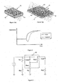
- a DEA generally referenced 10 comprises a dielectric elastomer membrane 11 provided between compliant electrodes 12.
- the dielectric elastomer membrane 11 is compressed by electrostatic pressure when a high voltage is applied across the electrodes 12 in the manner of a capacitor, causing planar expansion of the polymer from the uncompressed or contracted state as shown in Figure 1(a) , to the compressed or expanded state illustrated in Figure 1(b) .
- Natural muscle is much more than just an actuator, as it provides position feedback to the brain.
- Specialized cells within muscle tissue provide feedback to the body's central nervous system and this information is crucial to the coordination of muscle groups necessary for maintaining balance and posture.
- that feedback may include a pain signal when there is a danger of overexertion causing damage to the muscle or other parts of the body.
- Automatic reflex actions in response to this feedback can even occur without conscious thought, particularly in an attempt to prevent harm e.g. recoiling from a sharp object.
- Skeletal muscle is a key component in the distributed control system that is the human body.
- a DEA is constructed from a material which is resistant to compression, it is possible to relate a change in capacitance to changes in the physical geometry of the DEA.
- "An adaptive control method for dielectric elastomer devices” Todd A. Gisby, Emilio P. Calius, Shane Xie, and lain A. Anderson, Proc. SPIE, 2008 ), discloses the use of self-sensing based upon the capacitance between electrodes to determine the state of a DEA, thereby providing some feedback. Similar methods are disclosed by "Control system design for a dielectric elastomer actuator: The sensory subsystem” ( Toth, L.A. and A.A.
- the invention may broadly be said to consist in a method of determining the capacitance between opposing electrodes of a dielectric elastomer actuator (DEA), the method comprising the steps of:
- the error term is equal to the total instantaneous current through the DEA divided by the voltage difference between the electrodes of the DEA when the first derivative of the voltage difference between the electrodes of the DEA with respect to time is equal to zero.
- the DEA is supplied by a pulse-width modulated (PWM) current source having a limited slew rate on either or both edges.
- PWM pulse-width modulated
- the slew rate of the current source is selected to enable accurate detection of the zero-crossing of the first derivative of the voltage difference between the electrodes of the DEA with respect to time, thereby minimising sensitivity to errors in the sample timing when sampling the total instantaneous current through the DEA.
- the step of measuring the voltage difference between the electrodes of the DEA comprises approximating the voltage using a resistor ladder.
- the step of determining the first derivative of the voltage difference between the electrodes of the DEA with respect to time comprises approximating the first derivative using a differentiator circuit.
- the step of determining the first derivative of the voltage difference between the electrodes of the DEA with respect to time comprises approximating the first derivative using a finite difference method on sequential measurements of the voltage difference between the electrodes of the DEA.
- the step of measuring the total instantaneous current through the DEA comprises the step of measuring the voltage difference across a known series resistance.
- the invention may broadly be said to consist in a method of determining the leakage current between opposing electrodes of a dielectric elastomer actuator (DEA), the method comprising the steps of:
- the invention may broadly be said to consist in a method of determining the state of a dielectric elastomer actuator (DEA), the method comprising the steps of:
- the step of determining the state of the DEA comprises the steps of:
- the invention may broadly be said to consist in a method of controlling a dielectric elastomer actuator (DEA) comprising the steps of:
- the method further comprises the steps of:
- the invention may broadly be said to consist in a system for determining the capacitance between opposing electrodes of a dielectric elastomer actuator (DEA), the system comprising:
- the DEA monitoring circuit comprises:
- the means for measuring the voltage difference comprises a resistor ladder
- the means for measuring the first derivative of the voltage difference comprises a differentiator circuit
- the means for measuring the current through the DEA comprises a series resistor
- the error term is equal to the total instantaneous current through the DEA.divided by the voltage difference across the DEA when the first derivative of the voltage difference across the DEA with respect to time is equal to zero.
- the computation means is further adapted to determine the state of the DEA corresponding with the calculated capacitance.
- the computation means is further adapted to control the state of the DEA by way of controlling the current source.
- the invention may broadly be said to consist in a method of modelling or simulating a dielectric elastomer actuator (DEA), the method comprising the step of representing the DEA as an ideal capacitance augmented with an equivalent parallel resistance to account for leakage current, and an equivalent series resistance to account for the resistance of the electrodes.
- DEA dielectric elastomer actuator
- the invention may broadly be said to consist in a method of determining the state of a DEA, the method comprising the steps of:
- dielectric elastomer actuators resemble a compliant capacitor consisting of a resilient soft polymer membrane dielectric 11 with compliant electrodes 12 on substantially opposing sides of the membrane.
- the charge accumulated on the electrodes 12 after a voltage is applied gives rise to electrostatic forces that generate deformation in the DEA 10.
- the net result of the interaction between the positive and negative charges and the mechanical properties of the DEA produces a coupled decrease in dielectric membrane 11 thickness and increase in membrane planar area, as shown in Figure 1(b) .
- the elastic energy stored in the dielectric returns it to its original shape as shown in Figure 1(a) .
- Equation 1 The charge-generated surface pressure, or Maxwell stress, is proportional to the square of the electric field within the dielectric and can be described by Equation 1.
- P is the pressure
- ⁇ r is the relative permittivity of the dielectric material
- ⁇ 0 is the permittivity of free space (8.854x10 -12 F/m)
- V is the voltage
- d is the dielectric membrane thickness in meters.
- a feedback system provides feedback on the state of a dielectric elastomer actuator (DEA) 10, giving an indication of the extent to which the membrane 11 is compressed, and/or the corresponding planar expansion thereof.
- DEA dielectric elastomer actuator
- Sensing and feedback in actuators have typically required the incorporation of sensors such as optical sensors, strain gauges, micro-switches and the like which are external to the components of the actuator itself, creating an actuator/sensor hybrid. While the benefit of feedback allows improved control of the actuator, the sensors increase the component count and complexity of the actuator.
- An important property of DEAs is the potential for self-sensing, i.e. sensing an electrical property of the actuator itself. In particular, the state of a DEA can be determined by sensing the capacitance between the electrodes 12.
- a self-sensing artificial muscle has the potential to be more compact and simpler to construct than actuators incorporating external sensors owing to reduced component count, and may also provide a built-in safety mechanism whereby the health of the DEA can be monitored, as will be described in further detail below.
- capacitive self-sensing is not as simple as applying the capacitive sensing techniques commonly applied in other fields.
- DEAs represent a highly coupled electro-mechanical system. Where they are coupled to a "real world" load susceptible to non-deterministic disturbances, controlling them with any degree of accuracy becomes an interesting challenge. There is a complex exchange of electrical and mechanical energy; a high voltage input must be applied to achieve mechanical actuation, yet the mechanical response of the DEA (whether due to the electrical input energy or an external disturbance) affects the necessary input to achieve the desired output state. Feedback is necessary to achieve accurate control.
- Self-sensing can be implemented by measuring the capacitance of the DEA. Owing to the resilience or tendency of the dielectric membrane 11 to return to its original uncompressed state, it is possible to relate the capacitance of a DEA 10 to its state of deformation. Measuring the capacitance of a DEA 10 is important because with the instantaneous capacitance and voltage, the instantaneous electrostatic charge on the DEA can be calculated and therefore controlled. Controlling charge results in a stable system where the electrostatic response of the DEA will act to reject external physical disturbances. For instance if the DEA deforms such that the thickness is reduced, the capacitance will increase.
- a slew-rate controlled PWM signal is preferably used to create an input current waveform that creates both a DC offset for actuation and a dynamic high frequency excitation used for measuring capacitance.
- This approach builds upon the self-sensing technique for quasi-static DEA systems disclosed by Gisby et al. ( Todd A. Gisby, Emilio P. Calius, Shane Xie, and lain A. Anderson, "An adaptive control method for dielectric elastomer devices", Proc. SPIE, 2008 ).
- the preferred capacitive self-sensing technique takes into account the effects of leakage current and a non-zero first derivative of the DEA capacitance with respect to time, both of which were ignored in the self-sensing techniques of the prior art. Ignoring these effects results in a significant error in the predicted value of the capacitance during transient states of the actuator, as shown in Figure 2 . Accordingly, an electrical representation of a "real" DEA has been developed to determine how to approximate the influence of electrical behaviours within the DEA (that cannot be measured directly) using electrical parameters that can be measured.
- a DEA is not an ideal capacitor.
- the DEA is represented by an ideal capacitance (C dea ) augmented with an equivalent parallel resistance (R epr ) in parallel to account for leakage current and an equivalent series resistance (R esr ) to account for the resistance of the electrodes.
- C dea ideal capacitance
- R epr equivalent parallel resistance
- R esr equivalent series resistance
- the example DEA monitoring circuit illustrated in Figure 3 has been designed to obtain feedback information regarding the electrical behaviour of the circuit, wherein the DEA 10 is represented by the capacitor C dea (representing the capacitance between the electrodes 12) and resistors R esr and R epr within the dotted-line box.
- C dea , R epr , and R esr will vary depending on the electromechanical loading of the DEA.
- R p1 and R p2 represent a voltage divider ladder used to directly measure the voltage difference across the DEA.
- C hpf and R hpf represent a simple high pass filter that acts as a differentiator circuit and can be used to measure the rate of change of voltage across the DEA.
- the circuit has been designed to be driven by a low power, high voltage DC-DC converter coupled with a high voltage opto-coupler (such as the OC100HG, available from Voltage Multipliers, Inc.) or other suitable switch.
- a high voltage opto-coupler such as the OC100HG, available from Voltage Multipliers, Inc.
- the properties of these components combined can effectively be modelled as a current source.
- Equation 4 can be expanded to incorporate the full expression for i dea (from Equation 3) and i epr to become Equation 5, where V dea is the voltage across the capacitor C dea .
- i Rs C dea d ⁇ V dea dt + d ⁇ C dea dt ⁇ V dea + V dea R epr
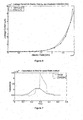
- Equation 5 The limitation of this approach is that ignoring the latter two terms of Equation 5 introduces an error that is proportional to the sum of the speed of actuation and the leakage current. Leakage current, for the common DEA membrane material VHB4905 at least, begins to degrade the accuracy of the calculation for electric fields greater than approximately 80-100MV/m as shown in Figure 6 . A more advanced approach is necessary to calculate capacitance where these simplifying assumptions do not hold.
- Equation 5 it is clear five parameters must be known in order to calculate C dea : i Rs , dV dea / dt, dC dea / dt, V dea , and R epr .
- V dea and dV dea / dt can be approximated using the resistor ladder and differentiator circuit respectively, and i Rs can be measured directly.
- Measuring i epr and dC dea / dt for all conditions however is impossible due to the closed loop formed by C dea and R epr internal to the DEA. For this reason it is necessary to lump the contribution of i epr and dC dea / df to the calculation of C dea into a combined term.
- K error i Rs V dea
- the method involves calculating an electrical characteristic (capacitance) of the circuit from other characteristics ( i Rs , dV dea / dt, dC dea / dt, V dea , and R epr ) which can be measured directly.
- the DEA capacitance C dea this value can be used to estimate or determine the position or state of the actuator corresponding therewith.
- the ratio ( ⁇ A ) of the instantaneous planar area of the DEA to its initial planar area, and therefore the displacement of the DEA can be determined using the relationship of Equation 10.
- ⁇ A C dea C initial
- the method provides more accurate feedback for the control of artificial muscles, whereby a computation means calculating the capacitance may be further adapted to control the artificial muscle by way of controlling the pulse width or duty cycle of a current source supplying the DEA such that the actual (determined) position or state of the actuator substantially matches a required state, thereby forming a closed feedback loop for more precise control of a mechanical system with which the artificial muscle may be coupled.
- Equation 5 can then be rearranged and used to back calculate the leakage current ( i epr ) according to Equation 11.
- Monitoring the leakage current can enable detection of the precursors to dielectric breakdown and failure of the DEA. It can therefore be used to stop overcharging of the membrane which leads to breakdown. For example, the charge on the DEA may be limited when the leakage current exceeds a predefined threshold. Detecting and preventing breakdown not only increases device reliability, but also enables the DEA to be driven closer to its performance limits with greater confidence.
- a numerical model of the circuit presented in Figure 3 can be created in The MathWorks, Inc.'s MATLAB ® , for example, to test the effectiveness of the new self-sensing approach compared with the simplified quasi-static expression described by Equation 6.
- the model simulates behaviour of the DEA system for conditions where the input control signal is held constant while the capacitance changes i.e. a situation analogous to the DEA being deformed by an external load. To do this the model takes arbitrary functions for input current, DEA capacitance, and DEA leakage current as inputs, and incrementally solves for the current through each branch of the circuit at each time step.
- the initial electrical characteristics of the components comprising the DEA have been modelled on experimental data obtained from a simple 24mm diameter expanding dot actuator made from a VHB4905 membrane stretched equibiaxially to 16 times its original area and bonded to a rigid circular plastic frame.
- This actuator has an initial dielectric membrane thickness of 31.25 ⁇ m and a rest capacitance of approximately 500pF.
- Figure 4 shows the schematic for the DEA 10 electrical subsystem that is the basis of the numerical model.
- the current entering/exiting the upper junction 40 in Figure 4 is expressed by Equation 12, where i in is the user defined input current, i Rp is the current through the resistor ladder used to measure the voltage across the DEA, i dea is the charging/discharging current flowing through the DEA, i epr is the leakage current through the thickness of the membrane, and i hpf is the current through the high pass filter.
- i in i Rp + i dea + i epr + i hpf
- the instantaneous current through the DEA ( i dea ) is evaluated for every time step and integrated to calculate the charge stored on the DEA.
- the instantaneous DEA capacitance at the next time step is interpolated from the capacitance input function, and the voltage across the DEA for the next iteration is found by dividing the new charge by the new capacitance.
- the current i Rp is easily evaluated as the sum of the DEA voltage and the voltage across the known series resistance divided by the total resistance of the external resistor ladder.
- the leakage current through the membrane ( i epr ) is modelled as an electric field dependent parameter.
- a relationship between electric field and leakage current was found by fitting an exponential curve to electric field versus leakage current data obtained experimental using the VHB4905 test actuator. The mathematical representation of this curve was then used to calculate the instantaneous i epr for each time step in the model simulation.
- the function for the leakage current can be defined completely arbitrarily, it is simply to add a degree of realism that it is based upon experimental data for a real DEA.
- Both the quasi-static and dynamic methods for calculating capacitance rely solely on parameters that can be measured directly i.e. i Rp , i Rs , and i hpf .
- Equation 14 C dea i hpf dt + d ⁇ C dea dt ⁇ V dea + V dea R epr
- Equation 15 i in - i Rp - i epr - dC dea dt ⁇ V dea 1 + C dea C hpf
- Equation 12 i dee can be evaluated algebraically using Equation 12.
- the input current was limited to a maximum of 100uA, and a maximum slew rate of 200mA/s was imposed on the falling edge of the input current waveform.
- a suitable slew rate is dependent on the actuator and the system.
- Leakage current data versus electric field for a VHB4905 expanding dot actuator stretched equibiaxially to 16 times its original area is presented in Figure 6 . Also shown in Figure 6 is an exponential curve that has been fitted to the raw data to provide a mathematical relationship between electric field and leakage current for use in the numerical model.
- An arbitrary input capacitance waveform was created with features corresponding to 5 conditions: a constant capacitance; a slow increase in capacitance; a fast increase in capacitance; a fast decrease in capacitance; and a slow decrease in capacitance.
- the input current waveform was fixed as a 500Hz PWM signal with a maximum value of 100uA and a limiting slew-rate of rate of 200mA/s was applied to the falling edge of the PWM signal.
- Leakage current was calculated based on the instantaneous electric field according to the relationship described in Equation 17. The simulation used a step size of 2 ⁇ s.
- Figure 7 displays the actual DEA capacitance compared to that predicted by the quasi-static self-sensing method based on Equation 6 in which the effects of dC dea / dt and leakage current are ignored.
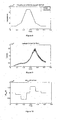
- Figure 8 compares the actual DEA capacitance with that predicted by the new dynamic self-sensing method described by Equation 9 in which the influence of dC dea / dt and leakage current are approximated using K error .
- Figures 9 and 10 show the leakage current and the magnitude of dC dea / dt respectively over the course of the simulation.
- the new dynamic self-sensing method offers a significant advantage in the accuracy between predicted and actual DEA capacitance compared to the previously presented quasi-static self-sensing method based on PWM.
- the accuracy of the quasi-static method is extremely sensitive to the rate of change of the DEA's capacitance.
- the magnitude of the error can clearly be seen in to be large where the absolute value of dC dea / dt is significant. For this reason the quasi-static approach to calculating capacitance is unsuitable for situations where high speed actuation, whether it is the result of a change in input signal or an external disturbance, is a possibility.
- the quasi-static method also lacks any inherent compensation for the effects of leakage current through the dielectric membrane.
- the impact of leakage current manifests itself in the steady state error observed between the true capacitance and the predicted capacitance on the flat region of the capacitance curve from 0.24 seconds to 0.29 seconds.
- Leakage current increases exponentially with electric field and becomes significant for electric fields greater than approximately 100MV/m.
- Anecdotal evidence suggests that for VHB4905 actuators operating above this electric field threshold typically will reduce the lifetime of the DEA considerably. Instead a maximum operating electric field of approximately 60-80MV/m produces longer-lasting devices. It must be pointed out, however, that better feedback from the DEA may extend the safe range of operation into the region where leakage current is significant. It is also important to consider that different dielectric membrane materials may have different leakage current characteristics than those observed for VHB4905. It is important therefore to account for this current where possible.
- the dynamic method is considerably more accurate for determining the DEA capacitance over the entire range of input conditions.
- the dynamic capacitance does lag behind the true capacitance by a small amount; however this lag is independent of the rate of change of capacitance and can easily be compensated for by the control system.
- the predicted capacitance shows very good agreement with the actual capacitance.
- the dynamic method in accounting for errors due to dC dea / dt and leakage current, effectively addresses the observed shortfalls of the quasi-static method.
- leakage current can enable detection of the precursors to dielectric breakdown. Detecting and preventing breakdown would not only increase device reliability, but also enable the DEA to be driven closer to its performance limits with greater confidence.
- the method of calculating capacitance requires dV dea / dt to be equal to zero in order to calculate the lumped error term K error , as described above.
- the dC dea / dt component may be so great that the derivative of the voltage across the DEA does not cross zero at any point during the PWM cycle. In this situation it is not possible to calculate the K error and therefore it is not possible to accurately compensate for this term.
- dV dea / dt may still be used to determine if the DEA is converting mechanical energy into electrical energy. In this situation the control system could switch to a generator mode and use the electrical energy created to recharge its power supply, for example.
- Dielectric Elastomer Actuators make them ideal candidates for artificial muscles. True artificial muscles however must be capable of acting as both sensor and an actuator at the same time.
- a numerical model of the electrical behaviour of a DEA has been created that incorporates the "non-ideal" characteristics of leakage current and the effects of a variable capacitance. This model has then been used to compare two methods for calculating the capacitance of a DEA: one simple quasi-static method in which the non-ideal elements are ignored; and another more advanced dynamic method that combines the effects of the non-ideal elements into a lumped parameter.
- the numerical model clearly shows the error between the actual capacitance and the predicted capacitance for the quasi-static method is highly sensitive to the rate of change of capacitance and only provides accurate measurements when the absolute value of dC dea / dt is small.
- the more dynamic method addresses the shortfalls of the quasi-static method and has been shown to be robust to changes in capacitance and variable leakage current. It also enables leakage current to be calculated which may prove a valuable step in detecting dielectric breakdown before it happens and subsequently greatly improves the reliability of DEA devices.
- the method described herein above may be implemented in a system for determining the capacitance, leakage current, and/or state/position of a dielectric elastomer (or a lever coupled therewith, for example) including a computation means.
- the computation means is preferably further adapted to control the DEA by varying the pulse-width of a current supply. Capacitive self-sensing in a DEA has been found to be robust to externally induced deformations of the DEA. A single power supply may be used to power multiple DEAs.
- FIG. 11 An example of a system including a feedback loop according to the present invention is shown in Figure 11 .
- the system comprises a DEA 10 mechanically coupled with a load 110 for controlled displacement thereof.
- the DEA is supplied by a pulse-width modulated (PWM) high voltage current source 111.
- PWM pulse-width modulated
- the PWM signal is supplied and controlled by the computation means 112 on the basis of feedback from the feedback sensors 113, which together with the DEA 10 form the DEA monitoring circuit described previously.
- the feedback sensors 113 comprise means for providing an indication or measurement of the voltage difference between electrodes of the DEA, the first derivative of the voltage difference between the electrodes of the DEA with respect to time, and the total instantaneous current through the DEA.
- Those means in the preferred embodiment of the invention comprise a resistor ladder, a differentiator circuit, and a series resistor (across which the potential difference can be measured to derive the current therethrough), respectively, although it is to be appreciated that any other suitable measurement or sensing means may alternatively be used without departing from the scope of the invention, and the selection and implementation of such sensing means is within the ambit of skills of any person knowledgeable in the area of electronic circuit design.
- the current source 111, computation means 112, and feedback sensors 113 can each be supplied by a low voltage power supply 114.
- the computation means 112 is programmed or otherwise adapted to calculate the capacitance of the DEA from other characteristics (i Rs , dV dea / dt, dC dea / dt, V dea , and R epr ) measured by the feedback sensors, and to relate this electrical characteristic to the physical state of the DEA 10. Any mismatch between the desired and calculated actual state may be corrected by adjusting the duty cycle of the PWM control signal to supply more or less charge to the DEA according to the difference, using proportional, integral, or differential control, or any combination thereof, for example. Any suitable control scheme may be used without departing from the scope of the invention.
- the system is battery powered and the computation means comprises a microcontroller.
- Other computer system configurations can also be employed to perform the method of this invention, and to the extent that a particular system configuration is capable of performing the method of this invention it is equivalent to the representative digital computer system described, and within the claimed scope of this invention. Once they are programmed to perform particular functions pursuant to instructions from program software that implements the method of this invention, such digital computer systems in effect become special-purpose computers particular to the method of this invention. The techniques necessary for this are well-known to those skilled in the art of computer systems.
- a microcontroller or other computation means 112 adapted to control a DEA using a method of self-sensing feedback as described herein above may be provided to control each artificial muscle in a mechanical system.
- the computation means 112 or microcontrollers may therefore provide distributed control of the muscles in the system.
- each microcontroller in the system may be communicatively coupled with a central control means acting to coordinate movement of the muscles in the system by communicating the movement required of each muscle to the respective microcontroller, and each microcontroller acts to control the respective muscle using the self-sensing dynamic feedback method.
- each microcontroller can actuate the muscle independently based in part on information or knowledge of the muscle, such as breakdown strength of the dielectric material or its frequency dependent properties in addition to the calculated leakage current and/or capacitance.
- the microcontroller can therefore monitor properties of the respective artificial muscle and automatically shut it down or limit the charge if the electric field is getting too high or the leakage current too great, preferably independently of any central control means.
- Such a circuit would be acting locally, to avoid damage without involving a higher system control, as in an autonomous nervous system.
- the muscle output can be optimized, reliability improved, and damage to the muscle can be avoided as the system will know its limits.
- a single computation means 112 may be used to simultaneously control two or more DEAs or artificial muscles as described herein.
- an improved method of determining the capacitance, and therefore state, of a dielectric elastomer actuator takes into account the both the speed of actuation and the leakage current. Accordingly, the method provides an accurate estimate of the dynamic capacitance and state of a DEA which is more suitable for providing feedback and therefore more precise control of artificial muscles.
- the methods and systems according to the invention provide a substantially accurate instantaneous indication of the continuously varying or dynamic capacitance of a DEA, whether through actuation or external perturbations, which may be used to more accurately determine the state of the DEA and provide more accurate and robust control thereof via closed-loop feedback.
- the system may be practically implemented in real-life applications, including those requiring portability and/or mobility.
- mobile robotics applications for example, it is important that the benefits of a soft, lightweight muscle-like actuator are not outweighed by the size and/or weight of bulky driving and support circuitry such that it becomes inefficient to use DEA.
- the present invention provides a relatively compact and simple system for controlling a DEA actuator, providing feedback on the actuator state without the need for external position sensors.
- a prosthetic hand using one or more DEA actuators as artificial muscles to be truly capable of replicating the functionality of a human hand requires accurate control and low mass, and it must not be tethered to a fixed installation (e.g. a mains power supply). Feedback is necessary to accurately control the artificial muscles in the prosthetic hand in an environment where a wide range of external loading conditions and/or disturbances are to be expected.
- Low mass is required to reduce the inertia of the device on the end of the wearer's arm.
- the system and/or method may be used to implement mechano-sensitivity allowing de-centralised control and coordination of a plurality of DEA actuators in an array, wherein the actuators themselves are each adapted to propagate an actuation signal by triggering actuation upon detecting deformation caused by contact from an adjacent actuator or a load.
- the system and/or method may be adapted for a wide range of other applications without departing from the scope of the invention.
Claims (18)
- System zum Bestimmen der Kapazität zwischen gegenüberliegenden Elektroden (12) eines dielektrischen Elastomeraktors (DEA, 10), das Folgendes umfasst:eine DEA-Überwachungsschaltung (113), zum Einholen von Feedback-Informationen bezüglich des elektrischen Verhaltens des DEAs (10); dadurch gekennzeichnet, dass das System Folgendes umfasst:Berechnungsmittel (112), das so ausgebildet ist, dass esdie Kapazität des DEA (10) als den Unterschied zwischen dem momentanen Gesamtstrom durch den DEA (10) und dem Produkt aus dem Spannungsunterschied über den DEA und einem Fehlerterm berechnet, wobei der Unterschied durch die erste Ableitung des Spannungsunterschieds über den DEA (10) nach der Zeit geteilt wird.
- System nach Anspruch 1, wobei die DEA-Überwachungsschaltung (113) Folgendes umfasst:eine pulsbreitenmodulierte Stromquelle (111);den dielektrischen Elastomeraktor (DEA) (10);Mittel zum Messen des Spannungsunterschied über den DEA;Mittel zum Messen der ersten Ableitung des Spannungsunterschieds über den DEA nach der Zeit; undMittel zum Messen des momentanen Gesamtstroms durch den DEA.
- System nach Anspruch 2, wobei das Mittel zum Messen des Spannungsunterschieds ein Widerstandsnetzwerk umfasst, das Mittel zum Messen der ersten Ableitung des Spannungsunterschieds eine Differenzierschaltung umfasst, und das Mittel zum Messen des Stroms durch den DEA einen Vorwiderstand umfasst.
- System nach einem der Ansprüche 1 bis 3, wobei der Fehlerterm gleich dem momentanen Gesamtstrom durch den DEA (10) geteilt durch den Spannungsunterschied über den DEA ist, wenn die erste Ableitung des Spannungsunterschieds über den DEA nach der Zeit gleich null ist.
- System nach einem der Ansprüche 1 bis 4, wobei das Berechnungsmittel ferner so ausgebildet ist, dass es den Zustand des DEA (10) entsprechend der berechneten Kapazität bestimmt.
- System nach einem der Ansprüche 1 bis 5, wobei das Berechnungsmittel (112) ferner so ausgebildet ist, dass es den Leckstrom des DEA (10) überwacht und die Ladung auf die Elektroden (12) einschränkt, wenn der Leckstrom eine vorgegebene Schwelle überschreitet.
- Verfahren zum Bestimmen der Kapazität zwischen gegenüberliegenden Elektroden eines dielektrischen Elastomeraktors (DEA, 10), wobei das Verfahren vom Berechnungsmittel (112) durchgeführt wird, und dadurch gekennzeichnet ist, dass das Verfahren die folgenden Schritte umfasst:Messen des Spannungsunterschieds zwischen den Elektroden (12) des DEAs (10);Bestimmen der ersten Ableitung des Spannungsunterschieds zwischen den Elektroden des DEAs (10) nach der Zeit;Messen des momentanen Gesamtstroms durch den DEA (10); undBerechnen der Kapazität des DEAs (10) als den Unterschied zwischen dem momentanen Gesamtstrom durch den DEA (10) und dem Produkt aus dem Spannungsunterschied zwischen den Elektroden des DEAs und einem Fehlerterm, wobei der Unterschied durch die erste Ableitung des Spannungsunterschieds zwischen den Elektroden (12) des DEAs (10) nach der Zeit geteilt wird.
- Verfahren nach Anspruch 7, wobei der Fehlerterm gleich dem momentanen Gesamtstrom durch den DEA geteilt durch den Spannungsunterschied zwischen den Elektroden (12) des DEAs (10) ist, wenn die erste Ableitung des Spannungsunterschieds zwischen den Elektroden des DEAs (10) nach der Zeit gleich null ist.
- Verfahren nach Anspruch 7 oder Anspruch 8, wobei der DEA (10) von einer pulsbreitenmodulierten (PWM) Stromquelle (111) gespeist wird, die an einer oder beiden Flanken eine begrenzte Flankensteilheit aufweist, wobei die Flankensteilheit der Stromquelle so ausgewählt wird, dass ein genaues Bestimmen des Nulldurchgangs der ersten Ableitung des Spannungsunterschieds zwischen den Elektroden des DEAs (10) nach der Zeit möglich ist, wodurch die Empfindlichkeit auf Fehler in der Abtastzeitwahl minimiert wird, wenn der momentane Gesamtstrom durch den DEA (10) abgetastet wird.
- Verfahren nach einem der Ansprüche 7 bis 9, wobei der Schritt des Messens des Spannungsunterschieds zwischen den Elektroden (12) des DEAs (10) das Approximieren der Spannung unter Verwendung eines Widerstandsnetzwerks umfasst.
- Verfahren nach einem der Ansprüche 7 bis 10, wobei der Schritt des Bestimmens der ersten Ableitung des Spannungsunterschieds zwischen den Elektroden (12) des DEAs (10) nach der Zeit das Approximieren der ersten Ableitung unter Verwendung einer Differenzierschaltung umfasst.
- Verfahren nach einem der Ansprüche 7 bis 10, wobei der Schritt des Bestimmens der ersten Ableitung des Spannungsunterschieds zwischen den Elektroden (12) des DEAs (10) nach der Zeit das Approximieren der ersten Ableitung unter Anwendung einer Finite-Differenzen-Methode auf sequenzielle Messungen des Spannungsunterschieds zwischen den Elektroden (12) des DEAs (10) umfasst.
- Verfahren nach einem der Ansprüche 7 bis 12, wobei der Schritt des Messens des momentanen Gesamtstroms durch das DEA (10) den Schritt des Messens des Spannungsunterschieds über einen bekannten Vorwiderstand umfasst.
- Verfahren zum Bestimmen des Leckstroms zwischen gegenüberliegenden Elektroden (12) eines dielektrischen Elastomeraktors (DEA, 10), wobei das Verfahren die folgenden Schritte umfasst:Bestimmen der Kapazität zwischen den Elektroden (12) gemäß dem Verfahren nach einem der Ansprüche 7 bis 13;Berechnen der ersten Ableitung der Kapazität nach der Zeit; undBerechnen des Leckstroms als den Unterschied zwischen dem momentanen Gesamtstrom durch den DEA (10) und dem Produkt aus dem Spannungsunterschied über den DEA (10) und der ersten Ableitung der Kapazität nach der Zeit zu einem Zeitpunkt, zu dem die erste Ableitung des Spannungsunterschieds über den DEA (10) nach der Zeit im Wesentlichen gleich null ist.
- Verfahren zum Bestimmen des Zustands eines dielektrischen Elastomeraktors (DEA, 10), wobei das Verfahren die folgenden Schritte umfasst:Bestimmen der Kapazität zwischen gegenüberliegenden Elektroden (12) des DEAs gemäß dem Verfahren nach einem der Ansprüche 7 bis 13; undBestimmen des Zustands des DEAs (10) entsprechend der Kapazität.
- Verfahren nach Anspruch 15, wobei der Schritt des Bestimmens des Zustands des DEAs (10) die folgenden Schritte umfasst:Bestimmen eines Kapazitätsverhältnisses der momentanen Kapazität des DEAs (10) zu seiner Anfangskapazität;Beziehen des Kapazitätsverhältnisses auf das Bereichsverhältnis zwischen dem momentanen Flächenbereich des DEAs (10) zu seinem Anfangsflächenbereich; undBestimmen der Verschiebung des DEAs (10) aus dem Verhältnis zwischen den Kapazitäts- und den Bereichsverhältnissen.
- Verfahren zum Steuern eines dielektrischen Elastomeraktors (DEA, 10), das die folgenden Schritte umfasst:Bestimmen des Zustands des DEAs (10) gemäß dem Verfahren nach Anspruch 15 oder Anspruch 16; undSteuern der Ladung auf den Elektroden (12) des DEAs (10) gemäß dem Unterschied zwischen dem bestimmten Zustand und einem erwünschten Zustand des DEAs (10).
- Verfahren nach Anspruch 17, das ferner die folgenden Schritte umfasst:Bestimmen des Leckstroms gemäß dem Verfahren nach Anspruch 14; undEinschränken der Ladung auf die Elektroden (12), wenn der Leckstrom eine vorgegebene Schwelle überschreitet.
Applications Claiming Priority (2)
| Application Number | Priority Date | Filing Date | Title |
|---|---|---|---|
| NZ57504009 | 2009-02-19 | ||
| PCT/NZ2010/000025 WO2010095960A1 (en) | 2009-02-19 | 2010-02-18 | System and method for dynamic self-sensing of dielectric elastomer actuators |
Publications (3)
| Publication Number | Publication Date |
|---|---|
| EP2399304A1 EP2399304A1 (de) | 2011-12-28 |
| EP2399304A4 EP2399304A4 (de) | 2013-08-14 |
| EP2399304B1 true EP2399304B1 (de) | 2015-06-03 |
Family
ID=42634074
Family Applications (1)
| Application Number | Title | Priority Date | Filing Date |
|---|---|---|---|
| EP10744003.4A Not-in-force EP2399304B1 (de) | 2009-02-19 | 2010-02-18 | System und verfahren zur dynamischen selbsterfassung von dielektrischen elastomer-aktoren |
Country Status (4)
| Country | Link |
|---|---|
| US (1) | US8860336B2 (de) |
| EP (1) | EP2399304B1 (de) |
| JP (1) | JP5773887B2 (de) |
| WO (1) | WO2010095960A1 (de) |
Families Citing this family (26)
| Publication number | Priority date | Publication date | Assignee | Title |
|---|---|---|---|---|
| WO2010093261A1 (en) * | 2009-02-09 | 2010-08-19 | Auckland Uniservices Limited | Mechano-sensitive actuator array |
| US8943884B2 (en) * | 2010-07-22 | 2015-02-03 | Baker Hughes Incorporated | Smart seals and other elastomer systems for health and pressure monitoring |
| CN103403902B (zh) * | 2010-10-18 | 2016-05-11 | 奥克兰联合服务有限公司 | 介电弹性体系统及估算介电弹性体状态的反馈参数的方法 |
| JP5288417B2 (ja) * | 2010-12-17 | 2013-09-11 | 国立大学法人信州大学 | 収縮型ゲルアクチュエータの制御方法 |
| US10314492B2 (en) | 2013-05-23 | 2019-06-11 | Medibotics Llc | Wearable spectroscopic sensor to measure food consumption based on interaction between light and the human body |
| CN104885243B (zh) * | 2012-06-14 | 2018-07-17 | 奥克兰大学服务有限公司 | 自感测介电弹性体装置 |
| US9582035B2 (en) | 2014-02-25 | 2017-02-28 | Medibotics Llc | Wearable computing devices and methods for the wrist and/or forearm |
| JP2014107319A (ja) * | 2012-11-26 | 2014-06-09 | Canon Inc | 接着力が制御可能な接着用部材 |
| US20170010130A1 (en) * | 2014-01-22 | 2017-01-12 | Daniel Xu | Pliable capacitive structure apparatus and methods |
| US10429888B2 (en) | 2014-02-25 | 2019-10-01 | Medibotics Llc | Wearable computer display devices for the forearm, wrist, and/or hand |
| CN107076623A (zh) * | 2014-07-03 | 2017-08-18 | 奥克兰大学服务有限公司 | 外部耦合传感器 |
| CA2966516A1 (en) | 2014-11-04 | 2016-05-12 | Ras Labs, Llc | Electroactive polymers and systems using the same |
| DE102015121047A1 (de) | 2015-12-03 | 2017-06-08 | Bürkert Werke GmbH | Ventilantrieb mit Stellungssensor |
| WO2018001839A1 (en) * | 2016-06-29 | 2018-01-04 | Koninklijke Philips N.V. | Eap actuator and drive method |
| US11036295B2 (en) | 2016-11-23 | 2021-06-15 | Microsoft Technology Licensing, Llc | Electrostatic slide clutch |
| EP3367450A1 (de) | 2017-02-22 | 2018-08-29 | Koninklijke Philips N.V. | Aktor- und sensorvorrichtung auf basis eines elektroaktiven polymers |
| EP3367451A1 (de) | 2017-02-23 | 2018-08-29 | Koninklijke Philips N.V. | Eine antriebsvorrichtung und eine antriebsmethode, mit einem elektroaktiven polymer-antrieb |
| JP6781648B2 (ja) | 2017-03-09 | 2020-11-04 | 正毅 千葉 | 誘電エラストマーセンサシステムおよび誘電エラストマーセンサ要素 |
| EP3451397A1 (de) * | 2017-08-28 | 2019-03-06 | Koninklijke Philips N.V. | Aktuatorvorrichtung und -verfahren |
| US11023047B2 (en) | 2018-05-01 | 2021-06-01 | Microsoft Technology Licensing, Llc | Electrostatic slide clutch with bidirectional drive circuit |
| CN108514907B (zh) * | 2018-06-21 | 2023-09-26 | 王立宗 | 砻谷机胶辊非接触式测量方法及结构、一种砻谷机 |
| US10852825B2 (en) | 2018-09-06 | 2020-12-01 | Microsoft Technology Licensing, Llc | Selective restriction of skeletal joint motion |
| US10860102B2 (en) | 2019-05-08 | 2020-12-08 | Microsoft Technology Licensing, Llc | Guide for supporting flexible articulating structure |
| US11061476B2 (en) | 2019-05-24 | 2021-07-13 | Microsoft Technology Licensing, Llc | Haptic feedback apparatus |
| US11054905B2 (en) | 2019-05-24 | 2021-07-06 | Microsoft Technology Licensing, Llc | Motion-restricting apparatus with common base electrode |
| CN114423491A (zh) * | 2019-07-17 | 2022-04-29 | Ue生命科学有限公司 | 通过使用电容式触觉传感器测量组织参数的系统和方法 |
Family Cites Families (9)
| Publication number | Priority date | Publication date | Assignee | Title |
|---|---|---|---|---|
| US7064472B2 (en) | 1999-07-20 | 2006-06-20 | Sri International | Electroactive polymer devices for moving fluid |
| US6809642B1 (en) | 2000-04-10 | 2004-10-26 | Robert Harry Brenner | Evacuation warning system for computer local area networks |
| JP2003133189A (ja) * | 2001-10-22 | 2003-05-09 | Nissan Diesel Motor Co Ltd | 漏れ電流の検査方法及び検査システム |
| JP2006109632A (ja) * | 2004-10-06 | 2006-04-20 | Olympus Corp | モータ制御回路及びその制御方法 |
| JP2008216074A (ja) | 2007-03-05 | 2008-09-18 | Yaskawa Electric Corp | 高分子アクチュエータの伸縮量センシング方法および伸縮量センシング装置 |
| US20100164324A1 (en) | 2007-07-23 | 2010-07-01 | Board Of Regents, University Of Nevada, Reno | Self-sensing dielectric actuator system |
| KR100949191B1 (ko) * | 2008-03-05 | 2010-03-23 | 성균관대학교산학협력단 | 유전 탄성체를 이용한 자가 센싱 액츄에이터 |
| WO2010093261A1 (en) * | 2009-02-09 | 2010-08-19 | Auckland Uniservices Limited | Mechano-sensitive actuator array |
| CN103403902B (zh) * | 2010-10-18 | 2016-05-11 | 奥克兰联合服务有限公司 | 介电弹性体系统及估算介电弹性体状态的反馈参数的方法 |
-
2010
- 2010-02-18 JP JP2011551029A patent/JP5773887B2/ja active Active
- 2010-02-18 US US13/202,536 patent/US8860336B2/en active Active
- 2010-02-18 EP EP10744003.4A patent/EP2399304B1/de not_active Not-in-force
- 2010-02-18 WO PCT/NZ2010/000025 patent/WO2010095960A1/en active Application Filing
Also Published As
| Publication number | Publication date |
|---|---|
| EP2399304A1 (de) | 2011-12-28 |
| WO2010095960A1 (en) | 2010-08-26 |
| US20120086366A1 (en) | 2012-04-12 |
| JP5773887B2 (ja) | 2015-09-02 |
| JP2012518384A (ja) | 2012-08-09 |
| US8860336B2 (en) | 2014-10-14 |
| EP2399304A4 (de) | 2013-08-14 |
Similar Documents
| Publication | Publication Date | Title |
|---|---|---|
| EP2399304B1 (de) | System und verfahren zur dynamischen selbsterfassung von dielektrischen elastomer-aktoren | |
| EP2630672B1 (de) | Selbstsensorisches dielektrisches elastomer mit ebenenannäherung | |
| Brufau-Penella et al. | Characterization of the harvesting capabilities of an ionic polymer metal composite device | |
| EP2008317B1 (de) | Verfahren und vorrichtung zum entnehmen von energie aus mechanischen vibrationen | |
| Sarban et al. | Dynamic electromechanical modeling of dielectric elastomer actuators with metallic electrodes | |
| Gisby et al. | Integrated sensing and actuation of muscle-like actuators | |
| Panigrahi et al. | An electrical model of a dielectric elastomer generator | |
| Bortot et al. | Analysis of viscoelastic soft dielectric elastomer generators operating in an electrical circuit | |
| Henke et al. | Modeling of dielectric elastomer oscillators for soft biomimetic applications | |
| Rizzello et al. | Simultaneous self-sensing of displacement and force for soft dielectric elastomer actuators | |
| Gisby et al. | An adaptive control method for dielectric elastomer devices | |
| Gisby et al. | Closed loop control of dielectric elastomer actuators | |
| Ye et al. | Self-sensing of dielectric elastomer actuator enhanced by artificial neural network | |
| Gupta et al. | Dynamic modeling and feedforward control of jaw movements driven by viscoelastic artificial muscles | |
| McKay et al. | An integrated dielectric elastomer generator model | |
| Behboodi et al. | Benchmarking of a commercially available stacked dielectric elastomer as an alternative actuator for rehabilitation robotic exoskeletons | |
| Illenberger et al. | The integrated self priming circuit: an autonomous electrostatic energy harvester with voltage boosting | |
| Choi et al. | Soft actuator for robotic applications based on dielectric elastomer: dynamic analysis and applications | |
| De Giuseppe et al. | An improved PZT cantilever SPICE model for practical energy harvesting circuits simulations and measurements | |
| Rizzello | Modeling, Control and Self-Sensing of Dielectric Elastomer Actuators | |
| Vu-Cong et al. | Autonomous dielectric elastomer generator using electret | |
| Yahud et al. | Experimental validation of a polyvinylidene fluoride sensing element in a tactile sensor | |
| Gisby | Smart artificial muscles | |
| NZ575040A (en) | System and method for dynamic self-sensing of dielectric elastomer actuators | |
| Ihlefeld et al. | A dielectric electroactive polymer generator-actuator model: modeling, identification, and dynamic simulation |
Legal Events
| Date | Code | Title | Description |
|---|---|---|---|
| PUAI | Public reference made under article 153(3) epc to a published international application that has entered the european phase |
Free format text: ORIGINAL CODE: 0009012 |
|
| 17P | Request for examination filed |
Effective date: 20110915 |
|
| AK | Designated contracting states |
Kind code of ref document: A1 Designated state(s): AT BE BG CH CY CZ DE DK EE ES FI FR GB GR HR HU IE IS IT LI LT LU LV MC MK MT NL NO PL PT RO SE SI SK SM TR |
|
| DAX | Request for extension of the european patent (deleted) | ||
| REG | Reference to a national code |
Ref country code: DE Ref legal event code: R079 Ref document number: 602010025062 Country of ref document: DE Free format text: PREVIOUS MAIN CLASS: H01L0041000000 Ipc: H01L0041040000 |
|
| A4 | Supplementary search report drawn up and despatched |
Effective date: 20130711 |
|
| RIC1 | Information provided on ipc code assigned before grant |
Ipc: H01L 41/04 20060101AFI20130705BHEP Ipc: H02N 2/06 20060101ALI20130705BHEP |
|
| GRAP | Despatch of communication of intention to grant a patent |
Free format text: ORIGINAL CODE: EPIDOSNIGR1 |
|
| INTG | Intention to grant announced |
Effective date: 20141217 |
|
| RIN1 | Information on inventor provided before grant (corrected) |
Inventor name: O ' BRIEN, BENJAMIN, MARC Inventor name: ANDERSON, IAIN ALEXANDER Inventor name: XIE, SHANE Inventor name: GISBY, TODD ALAN Inventor name: CALIUS, EMILIO, PATRICIO |
|
| GRAS | Grant fee paid |
Free format text: ORIGINAL CODE: EPIDOSNIGR3 |
|
| GRAA | (expected) grant |
Free format text: ORIGINAL CODE: 0009210 |
|
| AK | Designated contracting states |
Kind code of ref document: B1 Designated state(s): AT BE BG CH CY CZ DE DK EE ES FI FR GB GR HR HU IE IS IT LI LT LU LV MC MK MT NL NO PL PT RO SE SI SK SM TR |
|
| REG | Reference to a national code |
Ref country code: GB Ref legal event code: FG4D |
|
| REG | Reference to a national code |
Ref country code: CH Ref legal event code: EP |
|
| REG | Reference to a national code |
Ref country code: AT Ref legal event code: REF Ref document number: 730315 Country of ref document: AT Kind code of ref document: T Effective date: 20150715 Ref country code: IE Ref legal event code: FG4D |
|
| REG | Reference to a national code |
Ref country code: DE Ref legal event code: R096 Ref document number: 602010025062 Country of ref document: DE |
|
| REG | Reference to a national code |
Ref country code: AT Ref legal event code: MK05 Ref document number: 730315 Country of ref document: AT Kind code of ref document: T Effective date: 20150603 |
|
| PG25 | Lapsed in a contracting state [announced via postgrant information from national office to epo] |
Ref country code: NO Free format text: LAPSE BECAUSE OF FAILURE TO SUBMIT A TRANSLATION OF THE DESCRIPTION OR TO PAY THE FEE WITHIN THE PRESCRIBED TIME-LIMIT Effective date: 20150903 Ref country code: HR Free format text: LAPSE BECAUSE OF FAILURE TO SUBMIT A TRANSLATION OF THE DESCRIPTION OR TO PAY THE FEE WITHIN THE PRESCRIBED TIME-LIMIT Effective date: 20150603 Ref country code: LT Free format text: LAPSE BECAUSE OF FAILURE TO SUBMIT A TRANSLATION OF THE DESCRIPTION OR TO PAY THE FEE WITHIN THE PRESCRIBED TIME-LIMIT Effective date: 20150603 Ref country code: ES Free format text: LAPSE BECAUSE OF FAILURE TO SUBMIT A TRANSLATION OF THE DESCRIPTION OR TO PAY THE FEE WITHIN THE PRESCRIBED TIME-LIMIT Effective date: 20150603 Ref country code: FI Free format text: LAPSE BECAUSE OF FAILURE TO SUBMIT A TRANSLATION OF THE DESCRIPTION OR TO PAY THE FEE WITHIN THE PRESCRIBED TIME-LIMIT Effective date: 20150603 |
|
| REG | Reference to a national code |
Ref country code: NL Ref legal event code: MP Effective date: 20150603 |
|
| REG | Reference to a national code |
Ref country code: LT Ref legal event code: MG4D |
|
| PG25 | Lapsed in a contracting state [announced via postgrant information from national office to epo] |
Ref country code: AT Free format text: LAPSE BECAUSE OF FAILURE TO SUBMIT A TRANSLATION OF THE DESCRIPTION OR TO PAY THE FEE WITHIN THE PRESCRIBED TIME-LIMIT Effective date: 20150603 Ref country code: BG Free format text: LAPSE BECAUSE OF FAILURE TO SUBMIT A TRANSLATION OF THE DESCRIPTION OR TO PAY THE FEE WITHIN THE PRESCRIBED TIME-LIMIT Effective date: 20150903 Ref country code: LV Free format text: LAPSE BECAUSE OF FAILURE TO SUBMIT A TRANSLATION OF THE DESCRIPTION OR TO PAY THE FEE WITHIN THE PRESCRIBED TIME-LIMIT Effective date: 20150603 Ref country code: GR Free format text: LAPSE BECAUSE OF FAILURE TO SUBMIT A TRANSLATION OF THE DESCRIPTION OR TO PAY THE FEE WITHIN THE PRESCRIBED TIME-LIMIT Effective date: 20150904 |
|
| PG25 | Lapsed in a contracting state [announced via postgrant information from national office to epo] |
Ref country code: EE Free format text: LAPSE BECAUSE OF FAILURE TO SUBMIT A TRANSLATION OF THE DESCRIPTION OR TO PAY THE FEE WITHIN THE PRESCRIBED TIME-LIMIT Effective date: 20150603 |
|
| PG25 | Lapsed in a contracting state [announced via postgrant information from national office to epo] |
Ref country code: RO Free format text: LAPSE BECAUSE OF NON-PAYMENT OF DUE FEES Effective date: 20150603 Ref country code: SK Free format text: LAPSE BECAUSE OF FAILURE TO SUBMIT A TRANSLATION OF THE DESCRIPTION OR TO PAY THE FEE WITHIN THE PRESCRIBED TIME-LIMIT Effective date: 20150603 Ref country code: IS Free format text: LAPSE BECAUSE OF FAILURE TO SUBMIT A TRANSLATION OF THE DESCRIPTION OR TO PAY THE FEE WITHIN THE PRESCRIBED TIME-LIMIT Effective date: 20151003 Ref country code: PL Free format text: LAPSE BECAUSE OF FAILURE TO SUBMIT A TRANSLATION OF THE DESCRIPTION OR TO PAY THE FEE WITHIN THE PRESCRIBED TIME-LIMIT Effective date: 20150603 Ref country code: PT Free format text: LAPSE BECAUSE OF FAILURE TO SUBMIT A TRANSLATION OF THE DESCRIPTION OR TO PAY THE FEE WITHIN THE PRESCRIBED TIME-LIMIT Effective date: 20151006 Ref country code: CZ Free format text: LAPSE BECAUSE OF FAILURE TO SUBMIT A TRANSLATION OF THE DESCRIPTION OR TO PAY THE FEE WITHIN THE PRESCRIBED TIME-LIMIT Effective date: 20150603 |
|
| REG | Reference to a national code |
Ref country code: DE Ref legal event code: R097 Ref document number: 602010025062 Country of ref document: DE |
|
| PLBE | No opposition filed within time limit |
Free format text: ORIGINAL CODE: 0009261 |
|
| STAA | Information on the status of an ep patent application or granted ep patent |
Free format text: STATUS: NO OPPOSITION FILED WITHIN TIME LIMIT |
|
| PG25 | Lapsed in a contracting state [announced via postgrant information from national office to epo] |
Ref country code: IT Free format text: LAPSE BECAUSE OF FAILURE TO SUBMIT A TRANSLATION OF THE DESCRIPTION OR TO PAY THE FEE WITHIN THE PRESCRIBED TIME-LIMIT Effective date: 20150603 Ref country code: DK Free format text: LAPSE BECAUSE OF FAILURE TO SUBMIT A TRANSLATION OF THE DESCRIPTION OR TO PAY THE FEE WITHIN THE PRESCRIBED TIME-LIMIT Effective date: 20150603 |
|
| 26N | No opposition filed |
Effective date: 20160304 |
|
| PG25 | Lapsed in a contracting state [announced via postgrant information from national office to epo] |
Ref country code: BE Free format text: LAPSE BECAUSE OF NON-PAYMENT OF DUE FEES Effective date: 20160229 Ref country code: SI Free format text: LAPSE BECAUSE OF FAILURE TO SUBMIT A TRANSLATION OF THE DESCRIPTION OR TO PAY THE FEE WITHIN THE PRESCRIBED TIME-LIMIT Effective date: 20150603 |
|
| PG25 | Lapsed in a contracting state [announced via postgrant information from national office to epo] |
Ref country code: LU Free format text: LAPSE BECAUSE OF FAILURE TO SUBMIT A TRANSLATION OF THE DESCRIPTION OR TO PAY THE FEE WITHIN THE PRESCRIBED TIME-LIMIT Effective date: 20160218 Ref country code: MC Free format text: LAPSE BECAUSE OF FAILURE TO SUBMIT A TRANSLATION OF THE DESCRIPTION OR TO PAY THE FEE WITHIN THE PRESCRIBED TIME-LIMIT Effective date: 20150603 |
|
| REG | Reference to a national code |
Ref country code: CH Ref legal event code: PL |
|
| GBPC | Gb: european patent ceased through non-payment of renewal fee |
Effective date: 20160218 |
|
| PG25 | Lapsed in a contracting state [announced via postgrant information from national office to epo] |
Ref country code: CH Free format text: LAPSE BECAUSE OF NON-PAYMENT OF DUE FEES Effective date: 20160229 Ref country code: LI Free format text: LAPSE BECAUSE OF NON-PAYMENT OF DUE FEES Effective date: 20160229 |
|
| REG | Reference to a national code |
Ref country code: FR Ref legal event code: ST Effective date: 20161028 |
|
| REG | Reference to a national code |
Ref country code: IE Ref legal event code: MM4A |
|
| PG25 | Lapsed in a contracting state [announced via postgrant information from national office to epo] |
Ref country code: BE Free format text: LAPSE BECAUSE OF FAILURE TO SUBMIT A TRANSLATION OF THE DESCRIPTION OR TO PAY THE FEE WITHIN THE PRESCRIBED TIME-LIMIT Effective date: 20150603 |
|
| PG25 | Lapsed in a contracting state [announced via postgrant information from national office to epo] |
Ref country code: IE Free format text: LAPSE BECAUSE OF NON-PAYMENT OF DUE FEES Effective date: 20160218 Ref country code: FR Free format text: LAPSE BECAUSE OF NON-PAYMENT OF DUE FEES Effective date: 20160229 Ref country code: GB Free format text: LAPSE BECAUSE OF NON-PAYMENT OF DUE FEES Effective date: 20160218 |
|
| PG25 | Lapsed in a contracting state [announced via postgrant information from national office to epo] |
Ref country code: NL Free format text: LAPSE BECAUSE OF FAILURE TO SUBMIT A TRANSLATION OF THE DESCRIPTION OR TO PAY THE FEE WITHIN THE PRESCRIBED TIME-LIMIT Effective date: 20150603 Ref country code: SE Free format text: LAPSE BECAUSE OF FAILURE TO SUBMIT A TRANSLATION OF THE DESCRIPTION OR TO PAY THE FEE WITHIN THE PRESCRIBED TIME-LIMIT Effective date: 20150603 |
|
| PG25 | Lapsed in a contracting state [announced via postgrant information from national office to epo] |
Ref country code: MT Free format text: LAPSE BECAUSE OF FAILURE TO SUBMIT A TRANSLATION OF THE DESCRIPTION OR TO PAY THE FEE WITHIN THE PRESCRIBED TIME-LIMIT Effective date: 20150603 |
|
| REG | Reference to a national code |
Ref country code: DE Ref legal event code: R119 Ref document number: 602010025062 Country of ref document: DE |
|
| REG | Reference to a national code |
Ref country code: DE Ref legal event code: R073 Ref document number: 602010025062 Country of ref document: DE |
|
| REG | Reference to a national code |
Ref country code: DE Ref legal event code: R082 Ref document number: 602010025062 Country of ref document: DE Representative=s name: MAUCHER JENKINS, DE Ref country code: DE Ref legal event code: R082 Ref document number: 602010025062 Country of ref document: DE Representative=s name: MAUCHER JENKINS PATENTANWAELTE & RECHTSANWAELT, DE |
|
| REG | Reference to a national code |
Ref country code: DE Ref legal event code: R074 Ref document number: 602010025062 Country of ref document: DE |
|
| REG | Reference to a national code |
Ref country code: DE Ref legal event code: R082 Ref document number: 602010025062 Country of ref document: DE Representative=s name: MAUCHER JENKINS, DE Ref country code: DE Ref legal event code: R082 Ref document number: 602010025062 Country of ref document: DE Representative=s name: MAUCHER JENKINS PATENTANWAELTE & RECHTSANWAELT, DE |
|
| PG25 | Lapsed in a contracting state [announced via postgrant information from national office to epo] |
Ref country code: HU Free format text: LAPSE BECAUSE OF FAILURE TO SUBMIT A TRANSLATION OF THE DESCRIPTION OR TO PAY THE FEE WITHIN THE PRESCRIBED TIME-LIMIT; INVALID AB INITIO Effective date: 20100218 Ref country code: SM Free format text: LAPSE BECAUSE OF FAILURE TO SUBMIT A TRANSLATION OF THE DESCRIPTION OR TO PAY THE FEE WITHIN THE PRESCRIBED TIME-LIMIT Effective date: 20150603 Ref country code: CY Free format text: LAPSE BECAUSE OF FAILURE TO SUBMIT A TRANSLATION OF THE DESCRIPTION OR TO PAY THE FEE WITHIN THE PRESCRIBED TIME-LIMIT Effective date: 20150603 |
|
| PG25 | Lapsed in a contracting state [announced via postgrant information from national office to epo] |
Ref country code: TR Free format text: LAPSE BECAUSE OF FAILURE TO SUBMIT A TRANSLATION OF THE DESCRIPTION OR TO PAY THE FEE WITHIN THE PRESCRIBED TIME-LIMIT Effective date: 20150603 Ref country code: MK Free format text: LAPSE BECAUSE OF FAILURE TO SUBMIT A TRANSLATION OF THE DESCRIPTION OR TO PAY THE FEE WITHIN THE PRESCRIBED TIME-LIMIT Effective date: 20150603 Ref country code: MT Free format text: LAPSE BECAUSE OF FAILURE TO SUBMIT A TRANSLATION OF THE DESCRIPTION OR TO PAY THE FEE WITHIN THE PRESCRIBED TIME-LIMIT Effective date: 20160229 |
|
| PGFP | Annual fee paid to national office [announced via postgrant information from national office to epo] |
Ref country code: DE Payment date: 20190125 Year of fee payment: 10 |
|
| REG | Reference to a national code |
Ref country code: DE Ref legal event code: R119 Ref document number: 602010025062 Country of ref document: DE |
|
| PG25 | Lapsed in a contracting state [announced via postgrant information from national office to epo] |
Ref country code: DE Free format text: LAPSE BECAUSE OF NON-PAYMENT OF DUE FEES Effective date: 20200901 |