EP2399149B1 - Ultrasonic imaging with a variable refractive lens - Google Patents
Ultrasonic imaging with a variable refractive lens Download PDFInfo
- Publication number
- EP2399149B1 EP2399149B1 EP10707352A EP10707352A EP2399149B1 EP 2399149 B1 EP2399149 B1 EP 2399149B1 EP 10707352 A EP10707352 A EP 10707352A EP 10707352 A EP10707352 A EP 10707352A EP 2399149 B1 EP2399149 B1 EP 2399149B1
- Authority
- EP
- European Patent Office
- Prior art keywords
- transducers
- transmit
- array
- echo signals
- refractive lens
- Prior art date
- Legal status (The legal status is an assumption and is not a legal conclusion. Google has not performed a legal analysis and makes no representation as to the accuracy of the status listed.)
- Not-in-force
Links
Images


Classifications
-
- G—PHYSICS
- G01—MEASURING; TESTING
- G01S—RADIO DIRECTION-FINDING; RADIO NAVIGATION; DETERMINING DISTANCE OR VELOCITY BY USE OF RADIO WAVES; LOCATING OR PRESENCE-DETECTING BY USE OF THE REFLECTION OR RERADIATION OF RADIO WAVES; ANALOGOUS ARRANGEMENTS USING OTHER WAVES
- G01S7/00—Details of systems according to groups G01S13/00, G01S15/00, G01S17/00
- G01S7/52—Details of systems according to groups G01S13/00, G01S15/00, G01S17/00 of systems according to group G01S15/00
- G01S7/52017—Details of systems according to groups G01S13/00, G01S15/00, G01S17/00 of systems according to group G01S15/00 particularly adapted to short-range imaging
- G01S7/52023—Details of receivers
- G01S7/52025—Details of receivers for pulse systems
- G01S7/52026—Extracting wanted echo signals
- G01S7/52028—Extracting wanted echo signals using digital techniques
-
- G—PHYSICS
- G01—MEASURING; TESTING
- G01S—RADIO DIRECTION-FINDING; RADIO NAVIGATION; DETERMINING DISTANCE OR VELOCITY BY USE OF RADIO WAVES; LOCATING OR PRESENCE-DETECTING BY USE OF THE REFLECTION OR RERADIATION OF RADIO WAVES; ANALOGOUS ARRANGEMENTS USING OTHER WAVES
- G01S15/00—Systems using the reflection or reradiation of acoustic waves, e.g. sonar systems
- G01S15/88—Sonar systems specially adapted for specific applications
- G01S15/89—Sonar systems specially adapted for specific applications for mapping or imaging
- G01S15/8906—Short-range imaging systems; Acoustic microscope systems using pulse-echo techniques
- G01S15/8909—Short-range imaging systems; Acoustic microscope systems using pulse-echo techniques using a static transducer configuration
-
- G—PHYSICS
- G01—MEASURING; TESTING
- G01S—RADIO DIRECTION-FINDING; RADIO NAVIGATION; DETERMINING DISTANCE OR VELOCITY BY USE OF RADIO WAVES; LOCATING OR PRESENCE-DETECTING BY USE OF THE REFLECTION OR RERADIATION OF RADIO WAVES; ANALOGOUS ARRANGEMENTS USING OTHER WAVES
- G01S15/00—Systems using the reflection or reradiation of acoustic waves, e.g. sonar systems
- G01S15/88—Sonar systems specially adapted for specific applications
- G01S15/89—Sonar systems specially adapted for specific applications for mapping or imaging
- G01S15/8906—Short-range imaging systems; Acoustic microscope systems using pulse-echo techniques
- G01S15/895—Short-range imaging systems; Acoustic microscope systems using pulse-echo techniques characterised by the transmitted frequency spectrum
- G01S15/8956—Short-range imaging systems; Acoustic microscope systems using pulse-echo techniques characterised by the transmitted frequency spectrum using frequencies at or above 20 MHz
-
- G—PHYSICS
- G01—MEASURING; TESTING
- G01S—RADIO DIRECTION-FINDING; RADIO NAVIGATION; DETERMINING DISTANCE OR VELOCITY BY USE OF RADIO WAVES; LOCATING OR PRESENCE-DETECTING BY USE OF THE REFLECTION OR RERADIATION OF RADIO WAVES; ANALOGOUS ARRANGEMENTS USING OTHER WAVES
- G01S7/00—Details of systems according to groups G01S13/00, G01S15/00, G01S17/00
- G01S7/52—Details of systems according to groups G01S13/00, G01S15/00, G01S17/00 of systems according to group G01S15/00
- G01S7/52017—Details of systems according to groups G01S13/00, G01S15/00, G01S17/00 of systems according to group G01S15/00 particularly adapted to short-range imaging
- G01S7/52085—Details related to the ultrasound signal acquisition, e.g. scan sequences
- G01S7/5209—Details related to the ultrasound signal acquisition, e.g. scan sequences using multibeam transmission
-
- G—PHYSICS
- G01—MEASURING; TESTING
- G01S—RADIO DIRECTION-FINDING; RADIO NAVIGATION; DETERMINING DISTANCE OR VELOCITY BY USE OF RADIO WAVES; LOCATING OR PRESENCE-DETECTING BY USE OF THE REFLECTION OR RERADIATION OF RADIO WAVES; ANALOGOUS ARRANGEMENTS USING OTHER WAVES
- G01S7/00—Details of systems according to groups G01S13/00, G01S15/00, G01S17/00
- G01S7/52—Details of systems according to groups G01S13/00, G01S15/00, G01S17/00 of systems according to group G01S15/00
- G01S7/52017—Details of systems according to groups G01S13/00, G01S15/00, G01S17/00 of systems according to group G01S15/00 particularly adapted to short-range imaging
- G01S7/52085—Details related to the ultrasound signal acquisition, e.g. scan sequences
- G01S7/52095—Details related to the ultrasound signal acquisition, e.g. scan sequences using multiline receive beamforming
-
- G—PHYSICS
- G10—MUSICAL INSTRUMENTS; ACOUSTICS
- G10K—SOUND-PRODUCING DEVICES; METHODS OR DEVICES FOR PROTECTING AGAINST, OR FOR DAMPING, NOISE OR OTHER ACOUSTIC WAVES IN GENERAL; ACOUSTICS NOT OTHERWISE PROVIDED FOR
- G10K11/00—Methods or devices for transmitting, conducting or directing sound in general; Methods or devices for protecting against, or for damping, noise or other acoustic waves in general
- G10K11/18—Methods or devices for transmitting, conducting or directing sound
- G10K11/26—Sound-focusing or directing, e.g. scanning
- G10K11/30—Sound-focusing or directing, e.g. scanning using refraction, e.g. acoustic lenses
Definitions
- the invention relates to a method for producing an ultrasound image with a variable refractive lens.
- the invention further relates to an imaging system comprising a variable refractive lens arranged for producing an ultrasound image and to a computer program product being adapted to enable a computer system comprising at least one computer having data storage means associated therewith to control such imaging system.
- Conventional ultrasound is performed by using an array of elements to focus and steer ultrasound beams in a pulse-echo fashion.
- the signals received by the array are beamformed by delaying and summing them. By applying different delays to the same received data, multiple receive beams can be formed for a single transmit event.
- Systems today typically use 2 or 4 receive beams (or multi-lines) to increase frame rates.
- Fluid focus technology has been proposed for use in ultrasound imaging.
- a Fluid focus lens can be constructed from two immiscible liquids with differing sound speeds. Refraction occurs at the interface between the liquids and this can be used to focus or steer the ultrasound beam. When a voltage is applied between the liquid and the enclosure, electrowetting causes the meniscus to move. This allows the focal depth and inclination of the interface to be controlled by varying the voltage. Fluid focus technology accordingly provides a very flexible variable refractive lens with numerous applications in various kind of imaging, e.g. optical and ultrasonic imaging.
- Fluid focus technology is particularly suited for high frequency applications requiring small apertures (gravitational effects are problematic with larger lenses). Examples of this include intra-cardiac imaging with a catheter-based probe.
- a typical center frequency would be 25MHz. This corresponds to a wavelength • of 62 ⁇ m.
- the fluid focus technology offers a nice solution - it allows the beam to be coarse steered to form the image, but a high frequency single-element transducer can still be used.
- Unfortunately the fluid focus lens is only capable of being steering in a single direction at a time due to the fixed focus, so no receive multi-line is possible.
- it is not possible to carry out dynamic receive focusing whereby the receive focus is moved deeper as the line is received).
- the resulting images therefore have a fixed focus in both transmit and receive and this limits their resolution away from the focus.
- an improved method for producing an ultrasound image with a variable refractive lens would be advantageous, and in particular a more efficient and/or reliable method for such use would be advantageous.
- the invention preferably seeks to mitigate, alleviate or eliminate one or more of the above mentioned disadvantages singly or in any combination.
- the invention is particularly, but not exclusively, advantageous for providing a method for high frequency ultrasonic imaging with the transducers being larger sized than hitherto needed for high frequency applications.
- the array of transducers does not need to be "well-sampled”; i.e. having the width or size being comparably to the center wavelength of the ultrasonic signals to be received. This is particularly important at very high frequencies where well-sampled arrays would require very small elements that would be very challenging to manufacture.
- the width, W may be at least 10, 15 or 20 times larger than half the center wavelength of the transmit pulses.
- the present invention thereby enables simplified hardware implementation of transducers for ultrasonic imaging, preferably at high frequencies.
- all of the transducers in the array i.e. not just a subgroup, may have a width, W , significantly larger than half the center wavelength of the transmit pulses.
- each transducer, W may be higher than hitherto seen, especially for high frequencies of transmits.
- the number of transducers in the array, N_elements may be above 5, 10, 15 or 20.
- the transmit beam may be ultrasonic high frequency pulses, preferably with center frequency of at least 10 MHz, 20 MHz, 25 MHz, 30 MHz, 40 MHz or 50 MHz.
- At least a sub-group of transducers, in the said array of transducers may have a width, W , above 0.1, 0.2 or 0.3 mm.
- the transducers have almost same shape and size, but it is also not the case.
- the maximum accepted relationship between steering angle and grating lobe angle, M, of the refractive lens and the array of transducers may be in the interval of approximately 5-40%, preferably 10-35%, more preferably 15-25% depending on the specific choice of design for the ultrasonic imaging.
- N_transmits may be chosen from the group of ; 2, 4, 8, 16, 32, 64, and 128.
- SNR signal to noise ratio
- the lens shape of the variable refractive lens may be varied for different transmit beams i.e. coarse steering of the imaging beam can be made feasible by the lens.
- the variable refractive lens may be a fluid lens, preferably an electrowetting liquid lens.
- the present invention relates to an imaging system arranged for producing an ultrasound image, comprising:
- the invention relates to a computer program product being adapted to enable a computer system comprising at least one computer having data storage means associated therewith to control an imaging system according to the third aspect of the invention.
- This aspect of the invention is particularly, but not exclusively, advantageous in that the present invention may be implemented by a computer program product enabling a computer system to perform the operations of the second aspect of the invention.
- a computer program product may be provided on any kind of computer readable medium, e.g. magnetically or optically based medium, or through a computer based network, e.g. the Internet.
- the first, second and third aspect of the present invention may each be combined with any of the other aspects.
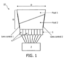
- Figure 1 is a schematic drawing of an imaging system 10 with a variable refractive lens 6 with a fluid 1 and a fluid 2.
- the lens is in this embodiment an electrowetting lens and further details and references about this lens can be found in "Apparatus for forming Variable Fluid Meniscus Configurations", WO 2004/0051323 and WO 2008/084455 both to the same applicant.
- the lens 6 has appropriate voltage control as indicated on the sides of the lens 6.
- an array 5 of transducers 4 is positioned underneath the lens 6, an array 5 of transducers 4 is positioned.
- the lens 6 is used to effect coarse steering. It steers the transmit beam and remains pointing in the same direction during receive. Echoes arriving from on axis (and from the receive focal depth) will be well-aligned across the multi-element array.
- the signals on the array elements are received by the multi-channel receive beamformer 7. This will typically be a digital sampling beamformer. By altering the relative delay between the signals received on the different elements, it is possible for the receive beamformer to steer the receive beam away from the on-axis direction (as defined by the fluid focus lens).
- the receive beamformer 7 can effect dynamic receive focusing by varying the inter-element delay during the receive event.
- the beam former 7 is shown underneath the lens 6 but in a practical imaging system, e.g. a catheter, the beam former may be positioned distant from the lens 6.
- An appropriate beamformer 7 for implementing the present invention can be found in WO 2007/133878 to the same applicant.
- a conventional scanning process can be represented on a transmit-receive diagram as shown in Figure 2 . Transmit beams and receive beams are in the same direction. Both are translated by the same amount between successive image lines. This sequence is represented by the stars on the transmit-receive diagram (right), which lie along the line with slope -1. An image can be formed by transmitting and receiving beams with different angular directions, or (as shown) with different lateral offsets.
- Figure 3 is a transmit-receive diagram for acquisition according to the present invention using a 4x beamformer for illustrative purposes.
- a multiline beamformer is capable of forming several receive lines for a single transmit event.
- the different receive lines are formed by applying different sets of delays to the same per-channel receive data. These receive lines correspond to receive beams that have different directions or different lateral offsets. With conventional imaging these multilines are usually used to increase the round-trip line density. For example, two receive beams can be used, one on either side of the transmit beam.
- the spacing between receive beams is equal to the spacing between transmit beams.
- the receive beams for successive transmit events overlap by 3.
- the lines received from a given transmit event are enclosed in a box encircling the stars representing the echo signals.
- the multilines are used in a special configuration.
- An example with a 4x multiline beamformer is shown in Figure 3 .
- the receive beams are parallel and spaced by an amount equal to the transmit spacing.
- the receive beams for successive transmits overlap by 3.
- the data aquistion of the echo signals corresponding to a given transmit beam can be made from one transmit event, i.e. four echo signals are received.
- a transmit event can give rise to the several echo signals but only one is received at first, and afterward a substantially identitical transmit event occurs and another echo signal in a "column" (receive direction) of figure 3 or 4 is received. This is repeated to sequentially obtain the echo signals corresponding to the given transmit beam. This sequential acquisition may be beneficial for simplified processing.
- Figure 5 is a graph showing the relative amplitude as a function of the relationship between array steering angle and grating lobe angle for an array of transducers i.e. the strength of main lobe and grating lobe for different steering angles.
- W is the width of the transducers.
- Zero angle corresponds to steering the receive in the same direction as the transmit.
- the value of 1 corresponds to steering the receive in the grating lobe direction.
- the vertical line shows the rule of thumb - steering angles less than 20% of the grating lobe angle are acceptable.
- D/W is simply the number of array elements in the transmit array. Therefore, the number of elements should be larger than or equal to 8, N_elements • 8.
- Figure 6 is schematic drawing illustrating the dynamic receive of echo signals. Inertial effects limit the speed at which the fluid focus lens can be adjusted. This means that the receive focus is usually fixed.
- the current invention can be used to effect dynamic focusing by varying the inter-element delays over the time that the signals are being received. This is shown in Figure 6 where wavefronts received from different depths within the medium containing the object have different curvatures. By varying the inter-element delay, the present invention may enable that the echoes are well-aligned no matter what depth they arrive from. The amounts of delay that are required are fairly small for this phased array configuration.
- target1 is at a depth of 2mm
- the current invention may also allow for dynamic apodization to be used.
- the receive aperture expands during the receive event: gradually more elements are added to the summation.
- the present invention may further be applied for focusing the transmit beam. If the array elements are individually connected to transmitters, then the waveforms transmitted by each element can be phased or time shifted to effect transmit focusing.
- the transmit can be focused or diverging. Transmit apodization is also possible.
- the invention can also be implemented using an annular array of transducers. This permits the use of dynamic focusing and apodization on receive. It also permits the use of different fixed focal depths and apodizations on transmit.
- the present invention can be used in the field of ultrasound imaging, in particular intra-cardiac catheter-based imaging. Such devices have been proposed for use in therapy monitoring for electrophysiology procedures for the treatment of atrial fibrillation.
- Figure 7 is a flow chart of a method according to the invention for producing an ultrasound image with a variable refractive lens 6, cf.
- Figure 1 comprising:
- the invention can be implemented in any suitable form including hardware, software, firmware or any combination of these.
- the invention or some features of the invention can be implemented as computer software running on one or more data processors and/or digital signal processors.
- the elements and components of an embodiment of the invention may be physically, functionally and logically implemented in any suitable way. Indeed, the functionality may be implemented in a single unit, in a plurality of units or as part of other functional units. As such, the invention may be implemented in a single unit, or may be physically and functionally distributed between different units and processors.
Landscapes
- Engineering & Computer Science (AREA)
- Physics & Mathematics (AREA)
- Radar, Positioning & Navigation (AREA)
- Remote Sensing (AREA)
- Computer Networks & Wireless Communication (AREA)
- General Physics & Mathematics (AREA)
- Acoustics & Sound (AREA)
- Multimedia (AREA)
- Ultra Sonic Daignosis Equipment (AREA)
- Investigating Or Analyzing Materials By The Use Of Ultrasonic Waves (AREA)
Applications Claiming Priority (2)
| Application Number | Priority Date | Filing Date | Title |
|---|---|---|---|
| US15414009P | 2009-02-20 | 2009-02-20 | |
| PCT/IB2010/050690 WO2010095094A1 (en) | 2009-02-20 | 2010-02-16 | Ultrasonic imaging with a variable refractive lens |
Publications (2)
| Publication Number | Publication Date |
|---|---|
| EP2399149A1 EP2399149A1 (en) | 2011-12-28 |
| EP2399149B1 true EP2399149B1 (en) | 2012-07-18 |
Family
ID=42173294
Family Applications (1)
| Application Number | Title | Priority Date | Filing Date |
|---|---|---|---|
| EP10707352A Not-in-force EP2399149B1 (en) | 2009-02-20 | 2010-02-16 | Ultrasonic imaging with a variable refractive lens |
Country Status (7)
| Country | Link |
|---|---|
| US (1) | US20120105645A1 (pt) |
| EP (1) | EP2399149B1 (pt) |
| JP (1) | JP2012518455A (pt) |
| CN (1) | CN102326093A (pt) |
| BR (1) | BRPI1005992A2 (pt) |
| RU (1) | RU2011138460A (pt) |
| WO (1) | WO2010095094A1 (pt) |
Families Citing this family (25)
| Publication number | Priority date | Publication date | Assignee | Title |
|---|---|---|---|---|
| US8764665B2 (en) * | 2007-05-03 | 2014-07-01 | Koninklijke Philips N.V. | Methods and apparatuses of microbeamforming with adjustable fluid lenses |
| US9788813B2 (en) | 2010-10-13 | 2017-10-17 | Maui Imaging, Inc. | Multiple aperture probe internal apparatus and cable assemblies |
| US9282945B2 (en) * | 2009-04-14 | 2016-03-15 | Maui Imaging, Inc. | Calibration of ultrasound probes |
| JP5666446B2 (ja) | 2008-08-08 | 2015-02-12 | マウイ イマギング,インコーポレーテッド | マルチアパーチャ方式の医用超音波技術を用いた画像形成方法及びアドオンシステムの同期方法 |
| EP2419022B1 (en) | 2009-04-14 | 2019-11-06 | Maui Imaging, Inc. | Multiple aperture ultrasound array alignment fixture |
| EP2536339B1 (en) | 2010-02-18 | 2024-05-15 | Maui Imaging, Inc. | Point source transmission and speed-of-sound correction using multi-aperture ultrasound imaging |
| US9668714B2 (en) | 2010-04-14 | 2017-06-06 | Maui Imaging, Inc. | Systems and methods for improving ultrasound image quality by applying weighting factors |
| KR101906838B1 (ko) | 2010-10-13 | 2018-10-11 | 마우이 이미징, 인코포레이티드 | 오목한 초음파 트랜스듀서들 및 3d 어레이들 |
| EP2785253B1 (en) | 2011-12-01 | 2023-11-15 | Maui Imaging, Inc. | Motion detection using ping-based and multiple aperture doppler ultrasound |
| JP2015503404A (ja) | 2011-12-29 | 2015-02-02 | マウイ イマギング,インコーポレーテッド | 任意経路のmモード超音波イメージング |
| CN104135937B (zh) | 2012-02-21 | 2017-03-29 | 毛伊图像公司 | 使用多孔超声确定材料刚度 |
| WO2014026185A1 (en) | 2012-08-10 | 2014-02-13 | Maui Imaging, Inc. | Calibration of multiple aperture ultrasound probes |
| CN104582582B (zh) | 2012-08-21 | 2017-12-15 | 毛伊图像公司 | 超声成像系统存储器架构 |
| US9510806B2 (en) | 2013-03-13 | 2016-12-06 | Maui Imaging, Inc. | Alignment of ultrasound transducer arrays and multiple aperture probe assembly |
| CN103126723B (zh) * | 2013-03-19 | 2014-09-24 | 飞依诺科技(苏州)有限公司 | 多波束的频率复合成像方法及系统 |
| US9883848B2 (en) | 2013-09-13 | 2018-02-06 | Maui Imaging, Inc. | Ultrasound imaging using apparent point-source transmit transducer |
| US10401493B2 (en) | 2014-08-18 | 2019-09-03 | Maui Imaging, Inc. | Network-based ultrasound imaging system |
| CN113729764A (zh) | 2016-01-27 | 2021-12-03 | 毛伊图像公司 | 具有稀疏阵列探测器的超声成像 |
| CN105606210A (zh) * | 2016-03-24 | 2016-05-25 | 成都世恩医疗科技有限责任公司 | 一种基于液体透镜的超声传感器阵列 |
| CN109147656B (zh) * | 2017-06-27 | 2021-01-22 | 京东方科技集团股份有限公司 | 显示面板的修复系统和修复方法 |
| ES2755516B2 (es) * | 2018-10-22 | 2021-08-30 | Univ Valencia Politecnica | Metodo de fabricacion de una lente y dispositivo de ultrasonidos que comprende dicha lente |
| CN109674491A (zh) * | 2019-02-13 | 2019-04-26 | 飞依诺科技(苏州)有限公司 | 超声成像宽波束发射方法及发射系统 |
| KR102588510B1 (ko) * | 2019-04-22 | 2023-10-12 | 현대자동차주식회사 | 차량용 안테나 시스템 및 그 제어 방법 |
| CN111887887A (zh) * | 2020-07-09 | 2020-11-06 | 聚融医疗科技(杭州)有限公司 | 一种基于透镜回波的超声系统通道损坏的检测方法及系统 |
| CN116077099B (zh) * | 2023-01-05 | 2024-08-16 | 中北大学 | 基于环形阵列多子阵快速图像重建的超声ct反射成像方法 |
Family Cites Families (8)
| Publication number | Priority date | Publication date | Assignee | Title |
|---|---|---|---|---|
| US5704105A (en) * | 1996-09-04 | 1998-01-06 | General Electric Company | Method of manufacturing multilayer array ultrasonic transducers |
| US6589177B1 (en) * | 2002-11-15 | 2003-07-08 | Koninklijke Philips Electronics N.V. | Method and apparatus for obtaining B-flow and B-mode data from multiline beams in an ultrasound imaging system |
| US7808717B2 (en) | 2002-12-03 | 2010-10-05 | Koninklijke Philips Electronics N.V. | Apparatus for forming variable fluid meniscus configurations |
| CN101442939B (zh) * | 2006-05-12 | 2012-05-30 | 皇家飞利浦电子股份有限公司 | 用于空间复合的回顾性动态发射聚焦 |
| WO2008084455A1 (en) | 2007-01-11 | 2008-07-17 | Koninklijke Philips Electronics, N.V. | Catheter for three-dimensional intracardiac echocardiography and system including the same |
| EP2124754A1 (en) * | 2007-01-24 | 2009-12-02 | Koninklijke Philips Electronics N.V. | Method and apparatus for ultrasonic detection of motion using adjustable fluid lenses |
| US8764665B2 (en) * | 2007-05-03 | 2014-07-01 | Koninklijke Philips N.V. | Methods and apparatuses of microbeamforming with adjustable fluid lenses |
| EP2166951A2 (en) * | 2007-07-11 | 2010-03-31 | Koninklijke Philips Electronics N.V. | Ultrasonic assembly with adjustable fluid lens |
-
2010
- 2010-02-16 RU RU2011138460/07A patent/RU2011138460A/ru unknown
- 2010-02-16 EP EP10707352A patent/EP2399149B1/en not_active Not-in-force
- 2010-02-16 BR BRPI1005992A patent/BRPI1005992A2/pt not_active IP Right Cessation
- 2010-02-16 JP JP2011550684A patent/JP2012518455A/ja not_active Withdrawn
- 2010-02-16 CN CN2010800082389A patent/CN102326093A/zh active Pending
- 2010-02-16 US US13/201,245 patent/US20120105645A1/en not_active Abandoned
- 2010-02-16 WO PCT/IB2010/050690 patent/WO2010095094A1/en active Application Filing
Also Published As
| Publication number | Publication date |
|---|---|
| CN102326093A (zh) | 2012-01-18 |
| EP2399149A1 (en) | 2011-12-28 |
| WO2010095094A1 (en) | 2010-08-26 |
| RU2011138460A (ru) | 2013-03-27 |
| JP2012518455A (ja) | 2012-08-16 |
| BRPI1005992A2 (pt) | 2016-02-16 |
| US20120105645A1 (en) | 2012-05-03 |
Similar Documents
| Publication | Publication Date | Title |
|---|---|---|
| EP2399149B1 (en) | Ultrasonic imaging with a variable refractive lens | |
| JP2807113B2 (ja) | 音響走査方法及び装置 | |
| EP0464440B1 (en) | Multifocal ultrasound imaging system | |
| US6183419B1 (en) | Multiplexed array transducers with improved far-field performance | |
| US5902241A (en) | Large-aperture imaging using transducer array with adaptive element pitch control | |
| EP3234635B1 (en) | Aspects of sonar systems or other acoustic imaging systems | |
| US20160100822A1 (en) | Beamforming apparatus and ultrasound diagnostic apparatus having the same | |
| EP1795917A2 (en) | Ultrasound imaging transducer array for synthetic aperture | |
| US8038620B2 (en) | Fresnel zone imaging system and method | |
| EP2043525A2 (en) | Ultrasound imaging system and method using multiline acquisition with high frame rate | |
| KR100274653B1 (ko) | 교차 어레이를 이용한 초음파 3차원영상화 방법 및 장치 | |
| JP2000157548A (ja) | 超音波散乱体をイメ―ジングするための方法及びシステム | |
| EP2847615B1 (en) | Ultrasound transducer arrays with variable patch geometries | |
| US20040122321A1 (en) | Multiplexer for connecting a multi-row ultrasound transducer array to a beamformer | |
| CN108885258B (zh) | 具有一维片块的二维超声阵列换能器 | |
| JP2019509856A5 (pt) | ||
| WO2014045073A1 (en) | Ultrasound imaging | |
| JP7401462B2 (ja) | 疎サンプリングによる超音波撮像ならびに関連する装置、システムおよび方法 | |
| JP7044723B2 (ja) | 大型線形アレイを備える高速合成集束超音波イメージング | |
| US11607194B2 (en) | Ultrasound imaging system with depth-dependent transmit focus | |
| WO2017220354A1 (en) | Rapid synthetic focus ultrasonic imaging with large linear arrays | |
| Chen et al. | A kerfless dual-layer transducer combined with beamforming by spatial matched filtering for high frame rate ultrasound imaging | |
| WO2018064828A1 (en) | System and method for driving ultrasound imaging transducers |
Legal Events
| Date | Code | Title | Description |
|---|---|---|---|
| PUAI | Public reference made under article 153(3) epc to a published international application that has entered the european phase |
Free format text: ORIGINAL CODE: 0009012 |
|
| 17P | Request for examination filed |
Effective date: 20110920 |
|
| AK | Designated contracting states |
Kind code of ref document: A1 Designated state(s): AT BE BG CH CY CZ DE DK EE ES FI FR GB GR HR HU IE IS IT LI LT LU LV MC MK MT NL NO PL PT RO SE SI SK SM TR |
|
| GRAP | Despatch of communication of intention to grant a patent |
Free format text: ORIGINAL CODE: EPIDOSNIGR1 |
|
| DAX | Request for extension of the european patent (deleted) | ||
| GRAS | Grant fee paid |
Free format text: ORIGINAL CODE: EPIDOSNIGR3 |
|
| GRAA | (expected) grant |
Free format text: ORIGINAL CODE: 0009210 |
|
| AK | Designated contracting states |
Kind code of ref document: B1 Designated state(s): AT BE BG CH CY CZ DE DK EE ES FI FR GB GR HR HU IE IS IT LI LT LU LV MC MK MT NL NO PL PT RO SE SI SK SM TR |
|
| REG | Reference to a national code |
Ref country code: GB Ref legal event code: FG4D |
|
| REG | Reference to a national code |
Ref country code: CH Ref legal event code: EP |
|
| REG | Reference to a national code |
Ref country code: AT Ref legal event code: REF Ref document number: 567149 Country of ref document: AT Kind code of ref document: T Effective date: 20120815 Ref country code: IE Ref legal event code: FG4D |
|
| REG | Reference to a national code |
Ref country code: DE Ref legal event code: R096 Ref document number: 602010002247 Country of ref document: DE Effective date: 20120913 |
|
| REG | Reference to a national code |
Ref country code: NL Ref legal event code: VDEP Effective date: 20120718 |
|
| REG | Reference to a national code |
Ref country code: AT Ref legal event code: MK05 Ref document number: 567149 Country of ref document: AT Kind code of ref document: T Effective date: 20120718 |
|
| REG | Reference to a national code |
Ref country code: LT Ref legal event code: MG4D Effective date: 20120718 |
|
| PG25 | Lapsed in a contracting state [announced via postgrant information from national office to epo] |
Ref country code: IS Free format text: LAPSE BECAUSE OF FAILURE TO SUBMIT A TRANSLATION OF THE DESCRIPTION OR TO PAY THE FEE WITHIN THE PRESCRIBED TIME-LIMIT Effective date: 20121118 Ref country code: LT Free format text: LAPSE BECAUSE OF FAILURE TO SUBMIT A TRANSLATION OF THE DESCRIPTION OR TO PAY THE FEE WITHIN THE PRESCRIBED TIME-LIMIT Effective date: 20120718 Ref country code: NO Free format text: LAPSE BECAUSE OF FAILURE TO SUBMIT A TRANSLATION OF THE DESCRIPTION OR TO PAY THE FEE WITHIN THE PRESCRIBED TIME-LIMIT Effective date: 20121018 Ref country code: AT Free format text: LAPSE BECAUSE OF FAILURE TO SUBMIT A TRANSLATION OF THE DESCRIPTION OR TO PAY THE FEE WITHIN THE PRESCRIBED TIME-LIMIT Effective date: 20120718 Ref country code: HR Free format text: LAPSE BECAUSE OF FAILURE TO SUBMIT A TRANSLATION OF THE DESCRIPTION OR TO PAY THE FEE WITHIN THE PRESCRIBED TIME-LIMIT Effective date: 20120718 Ref country code: FI Free format text: LAPSE BECAUSE OF FAILURE TO SUBMIT A TRANSLATION OF THE DESCRIPTION OR TO PAY THE FEE WITHIN THE PRESCRIBED TIME-LIMIT Effective date: 20120718 Ref country code: BE Free format text: LAPSE BECAUSE OF FAILURE TO SUBMIT A TRANSLATION OF THE DESCRIPTION OR TO PAY THE FEE WITHIN THE PRESCRIBED TIME-LIMIT Effective date: 20120718 Ref country code: CY Free format text: LAPSE BECAUSE OF FAILURE TO SUBMIT A TRANSLATION OF THE DESCRIPTION OR TO PAY THE FEE WITHIN THE PRESCRIBED TIME-LIMIT Effective date: 20120718 |
|
| PG25 | Lapsed in a contracting state [announced via postgrant information from national office to epo] |
Ref country code: PL Free format text: LAPSE BECAUSE OF FAILURE TO SUBMIT A TRANSLATION OF THE DESCRIPTION OR TO PAY THE FEE WITHIN THE PRESCRIBED TIME-LIMIT Effective date: 20120718 Ref country code: SE Free format text: LAPSE BECAUSE OF FAILURE TO SUBMIT A TRANSLATION OF THE DESCRIPTION OR TO PAY THE FEE WITHIN THE PRESCRIBED TIME-LIMIT Effective date: 20120718 Ref country code: PT Free format text: LAPSE BECAUSE OF FAILURE TO SUBMIT A TRANSLATION OF THE DESCRIPTION OR TO PAY THE FEE WITHIN THE PRESCRIBED TIME-LIMIT Effective date: 20121119 Ref country code: SI Free format text: LAPSE BECAUSE OF FAILURE TO SUBMIT A TRANSLATION OF THE DESCRIPTION OR TO PAY THE FEE WITHIN THE PRESCRIBED TIME-LIMIT Effective date: 20120718 Ref country code: LV Free format text: LAPSE BECAUSE OF FAILURE TO SUBMIT A TRANSLATION OF THE DESCRIPTION OR TO PAY THE FEE WITHIN THE PRESCRIBED TIME-LIMIT Effective date: 20120718 Ref country code: GR Free format text: LAPSE BECAUSE OF FAILURE TO SUBMIT A TRANSLATION OF THE DESCRIPTION OR TO PAY THE FEE WITHIN THE PRESCRIBED TIME-LIMIT Effective date: 20121019 |
|
| PG25 | Lapsed in a contracting state [announced via postgrant information from national office to epo] |
Ref country code: NL Free format text: LAPSE BECAUSE OF FAILURE TO SUBMIT A TRANSLATION OF THE DESCRIPTION OR TO PAY THE FEE WITHIN THE PRESCRIBED TIME-LIMIT Effective date: 20120718 |
|
| PG25 | Lapsed in a contracting state [announced via postgrant information from national office to epo] |
Ref country code: DK Free format text: LAPSE BECAUSE OF FAILURE TO SUBMIT A TRANSLATION OF THE DESCRIPTION OR TO PAY THE FEE WITHIN THE PRESCRIBED TIME-LIMIT Effective date: 20120718 Ref country code: CZ Free format text: LAPSE BECAUSE OF FAILURE TO SUBMIT A TRANSLATION OF THE DESCRIPTION OR TO PAY THE FEE WITHIN THE PRESCRIBED TIME-LIMIT Effective date: 20120718 Ref country code: EE Free format text: LAPSE BECAUSE OF FAILURE TO SUBMIT A TRANSLATION OF THE DESCRIPTION OR TO PAY THE FEE WITHIN THE PRESCRIBED TIME-LIMIT Effective date: 20120718 Ref country code: RO Free format text: LAPSE BECAUSE OF FAILURE TO SUBMIT A TRANSLATION OF THE DESCRIPTION OR TO PAY THE FEE WITHIN THE PRESCRIBED TIME-LIMIT Effective date: 20120718 |
|
| PLBE | No opposition filed within time limit |
Free format text: ORIGINAL CODE: 0009261 |
|
| STAA | Information on the status of an ep patent application or granted ep patent |
Free format text: STATUS: NO OPPOSITION FILED WITHIN TIME LIMIT |
|
| PG25 | Lapsed in a contracting state [announced via postgrant information from national office to epo] |
Ref country code: IT Free format text: LAPSE BECAUSE OF FAILURE TO SUBMIT A TRANSLATION OF THE DESCRIPTION OR TO PAY THE FEE WITHIN THE PRESCRIBED TIME-LIMIT Effective date: 20120718 Ref country code: SK Free format text: LAPSE BECAUSE OF FAILURE TO SUBMIT A TRANSLATION OF THE DESCRIPTION OR TO PAY THE FEE WITHIN THE PRESCRIBED TIME-LIMIT Effective date: 20120718 |
|
| 26N | No opposition filed |
Effective date: 20130419 |
|
| PG25 | Lapsed in a contracting state [announced via postgrant information from national office to epo] |
Ref country code: BG Free format text: LAPSE BECAUSE OF FAILURE TO SUBMIT A TRANSLATION OF THE DESCRIPTION OR TO PAY THE FEE WITHIN THE PRESCRIBED TIME-LIMIT Effective date: 20121018 |
|
| REG | Reference to a national code |
Ref country code: DE Ref legal event code: R097 Ref document number: 602010002247 Country of ref document: DE Effective date: 20130419 |
|
| PG25 | Lapsed in a contracting state [announced via postgrant information from national office to epo] |
Ref country code: MC Free format text: LAPSE BECAUSE OF NON-PAYMENT OF DUE FEES Effective date: 20130228 |
|
| PG25 | Lapsed in a contracting state [announced via postgrant information from national office to epo] |
Ref country code: ES Free format text: LAPSE BECAUSE OF FAILURE TO SUBMIT A TRANSLATION OF THE DESCRIPTION OR TO PAY THE FEE WITHIN THE PRESCRIBED TIME-LIMIT Effective date: 20121029 Ref country code: DE Free format text: LAPSE BECAUSE OF NON-PAYMENT OF DUE FEES Effective date: 20130903 |
|
| REG | Reference to a national code |
Ref country code: FR Ref legal event code: ST Effective date: 20131031 |
|
| REG | Reference to a national code |
Ref country code: IE Ref legal event code: MM4A |
|
| REG | Reference to a national code |
Ref country code: DE Ref legal event code: R119 Ref document number: 602010002247 Country of ref document: DE Effective date: 20130903 |
|
| PG25 | Lapsed in a contracting state [announced via postgrant information from national office to epo] |
Ref country code: IE Free format text: LAPSE BECAUSE OF NON-PAYMENT OF DUE FEES Effective date: 20130216 Ref country code: FR Free format text: LAPSE BECAUSE OF NON-PAYMENT OF DUE FEES Effective date: 20130228 |
|
| PG25 | Lapsed in a contracting state [announced via postgrant information from national office to epo] |
Ref country code: MT Free format text: LAPSE BECAUSE OF FAILURE TO SUBMIT A TRANSLATION OF THE DESCRIPTION OR TO PAY THE FEE WITHIN THE PRESCRIBED TIME-LIMIT Effective date: 20120718 |
|
| REG | Reference to a national code |
Ref country code: CH Ref legal event code: PL |
|
| GBPC | Gb: european patent ceased through non-payment of renewal fee |
Effective date: 20140216 |
|
| PG25 | Lapsed in a contracting state [announced via postgrant information from national office to epo] |
Ref country code: CH Free format text: LAPSE BECAUSE OF NON-PAYMENT OF DUE FEES Effective date: 20140228 Ref country code: LI Free format text: LAPSE BECAUSE OF NON-PAYMENT OF DUE FEES Effective date: 20140228 |
|
| PG25 | Lapsed in a contracting state [announced via postgrant information from national office to epo] |
Ref country code: GB Free format text: LAPSE BECAUSE OF NON-PAYMENT OF DUE FEES Effective date: 20140216 |
|
| PG25 | Lapsed in a contracting state [announced via postgrant information from national office to epo] |
Ref country code: SM Free format text: LAPSE BECAUSE OF FAILURE TO SUBMIT A TRANSLATION OF THE DESCRIPTION OR TO PAY THE FEE WITHIN THE PRESCRIBED TIME-LIMIT Effective date: 20120718 |
|
| PG25 | Lapsed in a contracting state [announced via postgrant information from national office to epo] |
Ref country code: TR Free format text: LAPSE BECAUSE OF FAILURE TO SUBMIT A TRANSLATION OF THE DESCRIPTION OR TO PAY THE FEE WITHIN THE PRESCRIBED TIME-LIMIT Effective date: 20120718 |
|
| PG25 | Lapsed in a contracting state [announced via postgrant information from national office to epo] |
Ref country code: MK Free format text: LAPSE BECAUSE OF FAILURE TO SUBMIT A TRANSLATION OF THE DESCRIPTION OR TO PAY THE FEE WITHIN THE PRESCRIBED TIME-LIMIT Effective date: 20120718 Ref country code: LU Free format text: LAPSE BECAUSE OF NON-PAYMENT OF DUE FEES Effective date: 20130216 Ref country code: HU Free format text: LAPSE BECAUSE OF FAILURE TO SUBMIT A TRANSLATION OF THE DESCRIPTION OR TO PAY THE FEE WITHIN THE PRESCRIBED TIME-LIMIT; INVALID AB INITIO Effective date: 20100216 |