EP2399015B1 - Method for estimating total filling of a combustion chamber of an engine - Google Patents
Method for estimating total filling of a combustion chamber of an engine Download PDFInfo
- Publication number
- EP2399015B1 EP2399015B1 EP10707320.7A EP10707320A EP2399015B1 EP 2399015 B1 EP2399015 B1 EP 2399015B1 EP 10707320 A EP10707320 A EP 10707320A EP 2399015 B1 EP2399015 B1 EP 2399015B1
- Authority
- EP
- European Patent Office
- Prior art keywords
- mass
- combustion chamber
- burnt gases
- fresh air
- estimation
- Prior art date
- Legal status (The legal status is an assumption and is not a legal conclusion. Google has not performed a legal analysis and makes no representation as to the accuracy of the status listed.)
- Active
Links
- 238000002485 combustion reaction Methods 0.000 title claims description 55
- 238000000034 method Methods 0.000 title claims description 25
- 239000007789 gas Substances 0.000 claims description 126
- 239000000203 mixture Substances 0.000 claims description 22
- 230000006870 function Effects 0.000 claims description 17
- 239000000446 fuel Substances 0.000 description 9
- 238000006073 displacement reaction Methods 0.000 description 5
- 230000006835 compression Effects 0.000 description 2
- 238000007906 compression Methods 0.000 description 2
- 238000010408 sweeping Methods 0.000 description 2
- 241000287107 Passer Species 0.000 description 1
- 238000004880 explosion Methods 0.000 description 1
- 230000007935 neutral effect Effects 0.000 description 1
Images


Classifications
-
- F—MECHANICAL ENGINEERING; LIGHTING; HEATING; WEAPONS; BLASTING
- F02—COMBUSTION ENGINES; HOT-GAS OR COMBUSTION-PRODUCT ENGINE PLANTS
- F02D—CONTROLLING COMBUSTION ENGINES
- F02D41/00—Electrical control of supply of combustible mixture or its constituents
- F02D41/02—Circuit arrangements for generating control signals
- F02D41/18—Circuit arrangements for generating control signals by measuring intake air flow
-
- F—MECHANICAL ENGINEERING; LIGHTING; HEATING; WEAPONS; BLASTING
- F02—COMBUSTION ENGINES; HOT-GAS OR COMBUSTION-PRODUCT ENGINE PLANTS
- F02D—CONTROLLING COMBUSTION ENGINES
- F02D2200/00—Input parameters for engine control
- F02D2200/02—Input parameters for engine control the parameters being related to the engine
- F02D2200/04—Engine intake system parameters
- F02D2200/0402—Engine intake system parameters the parameter being determined by using a model of the engine intake or its components
Definitions
- the invention relates to a method for estimating and estimating a mass Ma of fresh air admitted inside a combustion chamber of an engine cylinder during an engine cycle.
- the invention also relates to a method for estimating the total filling of supercharged fresh air in the combustion chamber and a vehicle equipped with the estimator.
- An engine cycle successively comprises the exhaust of the burnt gases from the combustion chamber, the admission of fresh air and fuel into the combustion chamber and the explosion of the mixture in this combustion chamber.
- an engine cycle corresponds to two piston round trips between the two extreme positions of its stroke, i.e. the top dead center (TDC) and the point low death (PMB).
- the exhaust of burnt gases lasts as long as the exhaust valve (s) are open.
- the fresh air intake lasts as long as the intake valve (s) are open.
- the power delivered by an internal combustion engine is a function of the amount of air introduced into the combustion chamber of this engine.
- This amount of air is itself proportional to the density of this air. Therefore, in case of high power demand, it is expected to increase this amount of air by means of compression of the air before it is admitted into this combustion chamber.
- This operation is more commonly called supercharging and can be carried out by a supercharging device such as a turbocharger or a driven compressor such as a screw compressor.
- this sweeping is obtained by simultaneously opening the exhaust and intake valves of the same combustion chamber for a few degrees to a few tens of degrees of angle of rotation of the crankshaft. Typically, this occurs at the end of the exhaust of the burnt gases and at the start of the intake of fresh air.
- the fact that the air pressure at the open intake valve is higher than the pressure at the exhaust valve creates an air flow which passes directly from the intake to the exhaust causing part of the residual burnt gases present in the combustion chamber to pass. This period during which the intake and exhaust valves are simultaneously open is called "valve crossing".
- a valve crossing may also be provided.
- burnt gases are drawn into the combustion chamber. It is said that the burnt gases are re-aspirated. This feature is known by the acronym IGR (Internal Gas Recirculation) or Internal Exhaust Gas Recirculation.
- the invention aims to remedy this drawback by proposing a more precise method making it possible to estimate the mass of fresh air admitted inside a combustion chamber.
- the embodiments of this method of estimating the mass Ma can include one or more of the characteristics corresponding to the variants described below.
- the estimation of the mass Mb of burnt gases comprises the estimation of a mass Mb_resi of residual burnt gases contained in the combustion chamber at the end of the exhaust of the burnt gases, and the estimation of a mass Mb_reasp of burnt gases re-aspirated inside the combustion chamber during the crossing of valves.
- This embodiment makes it possible to obtain a more precise estimate of the mass Mb since the residual mass of burnt gases and the mass of burnt gases re-aspirated during a crossing of valves are simultaneously taken into account.
- the estimation of the mass Mb_resi is obtained from a pressure P ECH of the burnt gases, from an interior volume of the combustion chamber at the end of the exhaust of the burnt gases, from a temperature T ECH of the burnt gases and a correction coefficient A ECH of the pressure P ECH whose value is function of an exhaust end angle and engine speed.
- This mode also makes it possible to obtain an accurate estimate of the mass of residual burnt gases in the combustion chamber at the end of the exhaust without the need to measure the pressure or the temperature inside the combustion chamber. combustion.
- the figure 1 schematically represents a vehicle 2 equipped with an internal combustion engine.
- vehicle 2 is a motor vehicle such as a car.
- the engine of vehicle 2 is equipped with several cylinders. However, to simplify the illustration, only one cylinder 6 of this combustion engine is shown in the figure 1 .
- a piston 8 is mounted movable in translation between a top dead center (TDC) and a bottom dead center (PMB).
- TDC top dead center
- PMB bottom dead center
- This piston 8 rotates a crank 10 of a crankshaft 12 via a connecting rod 14.
- the crankshaft 12 rotates, via a mechanism not shown, the drive wheels of the vehicle 2 such that the wheel 16.
- the cylinder 6 defines a combustion chamber 18 delimited by the upper part of the piston 8 and a cylinder head not shown.
- a fresh air intake duct 20 opens into the chamber 18 via an intake opening.
- An intake valve 24 is movable between a closed position in which it closes the fresh air opening in an airtight manner, and an open position in which the fresh air can be admitted inside the chamber 18 via the admission opening. The valve 24 is moved between its open position and its closed position by an actuator 26 of intake valves.
- a fuel injector 28 is provided in the line 20 to inject fuel into the fresh air admitted inside the chamber 18.
- the fresh air / fuel mixture begins to occur at inside the intake air duct.
- the duct 20 is fluidly connected to a compressor 30 of a turbocharger 32 capable of compressing the fresh air admitted inside the chamber 18.
- the fresh air thus compressed is called fresh supercharged air.
- a spark plug 34 capable of igniting the fresh air / fuel mixture opens into chamber 18. This spark plug is controlled by an ignition device 36.
- An exhaust duct 40 also opens into the interior of the chamber 18 via an exhaust opening.
- This exhaust opening can be closed by a valve 44 which can be moved between a closed position and an open position in which the burnt gases contained inside the chamber 18 can escape via the conduit 40.
- This valve 44 is moved between these open and closed positions by a valve actuator 46.
- the valve actuators 26 and 46 may be mechanical valve actuators.
- the end of the duct 40 opposite its opening which opens into the chamber 18 is fluidly connected to a turbine 48 of the turbocharger 32.
- This turbine 48 makes it possible in particular to relax the exhaust gases before sending them to an exhaust line 50.
- engine control unit 60 also known by the acronym ECU (Engine Control Unit).
- ECU Engine Control Unit
- the unit 60 is also connected to numerous sensors such as for example a sensor 62 of the position of the crankshaft 12 and a sensor 64 of the engine speed.
- the engine speed is defined here as the number of revolutions per minute made by the motor drive shaft.
- the figure 2 represents, in the form of a graph, the movements of the valves 24 and 44 relative to the movements of the piston 8 during an engine cycle.
- an axis 70 of the abscissas represents the displacement of the piston 8 between its top dead center and its bottom dead center noted, respectively, TDC and TDC on this graph.
- the ordinate axis represents the amplitude of movement of the intake and exhaust valves. This amplitude is zero when the intake valve or the exhaust valve is closed. It is maximum when these same valves are fully open.
- the displacement of the valve 44 is represented by a curve 72 and the displacement of the valve 24 is represented by a curve 74.
- the axis 70 is graduated in degrees of angle of rotation of the crankshaft. The origin of this axis is confused with the top dead center of fresh air intake.
- the exhaust valve begins to open at an angle OE located substantially around the bottom dead center of expansion and closes at an angle FE.
- the FE angle is located after the top intake neutral point.
- the inlet valve begins to open at an angle OA and closes at an angle FA.
- this graph is represented in the particular case where a valve crossing exists. Indeed, the angle OA precedes the angle FE, which indicates that during a period of a few degrees, the intake and exhaust valves are simultaneously open.
- the figure 3 represents in more detail a possible architecture for the unit 60 for estimating the mass Ma and the total filling repl_tot.
- the unit 60 implements an estimator 80 of a temperature T ECH of the burnt gases, an estimator 82 of a pressure P ECH of the gases, an estimator 84 of a temperature T ADM of the fresh air admitted to inside the chamber 18 via the conduit 20, and an estimator 86 of a pressure P ADM of the fresh air admitted inside the chamber 18.
- estimators 80, 82, 84 and 86 are connected to an estimator 88 of the mass Ma and of the total filling repl_tot.
- This estimator 88 is also connected to a block 90 of engine controls.
- This block 90 makes it possible in particular to control the various actuators, injectors and ignition devices of the engine as a function of the estimates of the mass Ma and of the total filling repl_tot.
- the block 90 is capable of adjusting the quantity of fuel injected and of advancing the instant of ignition of the fresh air / fuel mixture injected into the chamber 18 or of adjusting the opening of a butterfly valve making it possible to adjust the quantity of fresh air admitted inside the chamber 18.
- the estimator 88 comprises a module 92 for estimating a mass Mb of burnt gases contained in the chamber 18 at the end of the exhaust of the burnt gases, an estimator 94 of a mass Mbal of gases swept from the intake towards the exhaust when the valves cross, an estimator 96 of the temperature Tb of the burnt gases, an estimator 98 of the mass Ma of fresh air admitted into the chamber 18, and an estimator 100 of the total filling repl_tot.
- the module 92 presents a sub-module 102 for estimating a mass Mb_resi of residual burnt gases contained in the chamber 18 at the end of the exhaust, and a sub-module 104 for estimating a mass Mb_reasp of burnt exhaust gases when the valves cross inside the chamber 18.
- the unit 60 is typically produced from a programmable computer capable of executing instructions recorded in an information storage means.
- the unit 60 is connected to a memory 106 containing the various instructions and data necessary for the execution of the process of the figure 4 .
- the different maps used to implement the process of figure 4 are stored in this memory 106. These maps are for example constructed experimentally so as to minimize the errors between the estimated values and the real values.
- the general principle is based on a mass balance on an engine cycle of the gases entering and leaving the chamber 18. This mass balance is broken down into several calculations which take place throughout the engine cycle.
- the mass Mb of gas burned in the chamber 18 is estimated.
- the total mass Mtot of gas contained inside the chamber 18 is estimated.
- the mass Ma of air contained inside the chamber 18 during an engine cycle can be obtained by subtracting the mass Mb to mass Mtot.
- the estimate of the mass Mb is broken down into an estimate of the mass Mb_resi of residual burnt gases not discharged by through the conduit 40 at the end of the exhaust and the mass Mb_reasp of burnt gas re-aspirated during the crossing of valves.
- repl_cyl My MB
- Ma the mass of air contained in the chamber 18 at the end of the admission
- Mo the reference mass
- the normal temperature and pressure conditions correspond to a temperature of 298.15 K, to a pressure of 1013 mbar, and to a volume equal to the volume of the unit displacement.
- the quantities repl_tot, repl_cyl and the Mbal / Mo ratio are dimensionless quantities.
- the mass Mbal exists only in the case of supercharged engines.
- the description of the process which follows is made in the most complete case, that is to say the case where the estimates of the masses Mb_reasp and Mbal are both carried out. Indeed, a person skilled in the art can easily simplify the following process to adapt it only to the case of naturally aspirated engines or only to the case of supercharged engines.
- the method begins with a step 120 of estimating the mass Mb_resi of burnt gas contained in the chamber 18 at the end of the exhaust.
- V cyl_FE Cu ⁇ - 1 + Cu 2 1 + ⁇ - cos FE - ⁇ 2 - sin 2 FE
- ⁇ is the rod / crank ratio
- Cu is the unit displacement of cylinder 6
- ⁇ is the engine compression ratio
- the ratio ⁇ and the rate ⁇ are known characteristics of an engine. It is simply recalled here that the ratio ⁇ is the ratio between the length of the connecting rod 14 divided by the half-length of the crank 18.
- the pressures P ECH and P ADM and the temperatures T ECH and T ADM are the pressures and temperatures estimated by the estimators 80, 82, 84 and 86 from physical quantities measured in engine.
- the sub-module 104 estimates the mass Mb_reasp of burnt gases re-aspirated during the crossing of valves.
- Mb _ reasp Mb _ reasp ⁇ K or Mb _ reasp ⁇ is the flow rate of re-aspirated burnt gases expressed in kg / h, and K is a coefficient making it possible to pass from the flow rate to a mass admitted per engine cycle in chamber 18.
- K NOT ⁇ No. _ cylinder No. _ revolutio not _ cycle ⁇ 60
- N is the engine speed
- Nbre_cylindre is the number of cylinder of the engine
- Nbre_revolutioncycle is the number of revolution of the crankshaft during a cycle of engine
- 60 converts the engine speed N given in revolutions per minute to the number of revolutions per hour.
- K N x 2 x 60.
- the module 94 estimates the total mass Mbal_tot of gas swept between the intake and the exhaust during the crossing of valves.
- the position of the valve crossing is equal to the following value: (FE + OA) / 2.
- the temperature Tb_reasp is taken equal to the temperature TECH.
- Tb_resi T ECH ⁇ 1 ⁇ + ⁇ - 1 ⁇ ⁇ P ADM P ECH where all the variables have already been previously defined.
- the relationship defining the temperature T mixture is obtained by a calculation of enthalpy mixture between the mass of burnt gases and the mass of fresh air contained in the chamber 18.
- the system of equations described above is a system of equations with three unknowns and three equations.
- the resolution of this system makes it possible to obtain estimates of the mass Ma, of the temperature T mixture and of the total mass Mtot.
- the estimate of the mass Ma obtained after solving the system of equations is corrected as a function of the inverse of the temperature Ta of the fresh air.
- the module 100 estimates the total filling repl_tot in fresh air.
Description
L'invention concerne un procédé d'estimation et un estimateur d'une masse Ma d'air frais admise à l'intérieur d'une chambre de combustion d'un cylindre d'un moteur lors d'un cycle moteur. L'invention a également pour objet un procédé d'estimation du remplissage total en air frais suralimenté de la chambre de combustion et un véhicule équipé de l'estimateur.The invention relates to a method for estimating and estimating a mass Ma of fresh air admitted inside a combustion chamber of an engine cylinder during an engine cycle. The invention also relates to a method for estimating the total filling of supercharged fresh air in the combustion chamber and a vehicle equipped with the estimator.
Un cycle moteur comprend successivement l'échappement des gaz brulés de la chambre de combustion, l'admission d'air frais et de carburant dans la chambre de combustion et l'explosion du mélange dans cette chambre de combustion. Dans le cas d'un moteur quatre temps, un cycle moteur correspond à deux allers-retours de piston dans le cylindre entre les deux positions extrêmes de sa course, c'est-à-dire le point mort haut (PMH) et le point mort bas (PMB).An engine cycle successively comprises the exhaust of the burnt gases from the combustion chamber, the admission of fresh air and fuel into the combustion chamber and the explosion of the mixture in this combustion chamber. In the case of a four-stroke engine, an engine cycle corresponds to two piston round trips between the two extreme positions of its stroke, i.e. the top dead center (TDC) and the point low death (PMB).
L'échappement de gaz brûlés dure tant que la ou les soupapes d'échappement sont ouvertes. De façon similaire, l'admission d'air frais dure tant que la ou les soupapes d'admission sont ouvertes.The exhaust of burnt gases lasts as long as the exhaust valve (s) are open. Similarly, the fresh air intake lasts as long as the intake valve (s) are open.
Comme cela est connu, la puissance délivrée par un moteur à combustion interne est fonction de la quantité d'air introduite dans la chambre de combustion de ce moteur. Cette quantité d'air est elle-même proportionnelle à la densité de cet air. De ce fait, en cas de demande de forte puissance, il est prévu d'augmenter cette quantité d'air aux moyens d'une compression de l'air avant qu'il ne soit admis dans cette chambre de combustion. Cette opération est plus communément appelée suralimentation et peut être réalisée par un dispositif de suralimentation comme un turbocompresseur ou un compresseur entraîné tel qu'un compresseur à vis.As is known, the power delivered by an internal combustion engine is a function of the amount of air introduced into the combustion chamber of this engine. This amount of air is itself proportional to the density of this air. Therefore, in case of high power demand, it is expected to increase this amount of air by means of compression of the air before it is admitted into this combustion chamber. This operation is more commonly called supercharging and can be carried out by a supercharging device such as a turbocharger or a driven compressor such as a screw compressor.
Afin d'augmenter encore plus cette quantité d'air admise dans le cylindre, il peut être prévu de réaliser un mode d'admission avec un balayage des gaz brûlés résiduels. Ce balayage permet d'évacuer les gaz brûlés présents dans la chambre de combustion pour les remplacer par de l'air suralimenté.In order to further increase this quantity of air admitted into the cylinder, provision may be made for carrying out an admission mode with a sweeping of the residual burnt gases. This sweep evacuates the burnt gases present in the combustion chamber to replace them with supercharged air.
Comme cela est expliqué dans le brevet
Dans le cas des moteurs atmosphériques, c'est-à-dire des moteurs dépourvus de suralimentation, un croisement de soupapes peut également être prévu. Dans ce cas, pendant le croisement de soupapes, des gaz brûlés sont aspirés dans la chambre de combustion. On dit que les gaz brûlés sont ré-aspirés. Cette fonctionnalité est connue sous l'acronyme d'IGR (Internai Gaz Recirculation) ou Recirculation Interne de Gaz d'échappement.In the case of naturally aspirated engines, that is to say engines without supercharging, a valve crossing may also be provided. In this case, during the valve crossing, burnt gases are drawn into the combustion chamber. It is said that the burnt gases are re-aspirated. This feature is known by the acronym IGR (Internal Gas Recirculation) or Internal Exhaust Gas Recirculation.
Des procédés d'estimation du débit d'air frais admis à l'intérieur d'une chambre de combustion d'un cylindre d'un moteur sont connus, par exemple du document
L'invention vise à remédier à cet inconvénient en proposant un procédé plus précis permettant d'estimer la masse d'air frais admise à l'intérieur d'une chambre de combustion.The invention aims to remedy this drawback by proposing a more precise method making it possible to estimate the mass of fresh air admitted inside a combustion chamber.
Elle a donc pour objet un procédé d'estimation d'un remplissage total rempl_tot en air frais suralimenté d'une chambre de combustion d'un cylindre d'un moteur lors d'un cycle moteur, comprenant
- l'estimation d'une masse Ma d'air frais admis à l'intérieur de la chambre de combustion d'un cylindre d'un moteur lors d'un cycle moteur mis en œuvre par un calculateur électronique,
- l'estimation d'une masse totale Mtot de gaz contenue dans la chambre de combustion à la fin de l'admission de l'air frais, l'estimation d'une masse Mb de gaz brûlés contenue dans la chambre de combustion à la fin de l'échappement des gaz brûlés, et l'estimation de la masse Ma d'air frais à partir de la différence entre la masse totale Mtot et la masse Mb de gaz brûlés estimées,

- Mtot est la masse totale de gaz contenue dans la chambre de combustion à la fin de l'admission de l'air frais définie précédemment,
- Mo est une masse de référence d'air dans les conditions normales de températures et de pression
- Mb est une masse de gaz brûlés contenue dans la chambre de combustion à la fin de l'échappement des gaz brûlés
- Mbal_tot est la masse totale de gaz balayé (air ou gaz brûlé) pendant le croisement de soupapes,
- Mbal est la masse de gaz balayé (air) entre l'admission et l'échappement pendant le croisement de soupapes,
- Max(...) et Min(...) sont respectivement les fonctions retournant le maximum et le minimum, et
- |...| est la valeur absolue.
- l'estimation d'une masse Mbal_tot de gaz balayés de l'admission vers l'échappement lors du croisement de soupapes,
- l'estimation du remplissage total rempl_tot en air frais suralimenté à partir de la masse d'air frais Ma et de la masse Mbal_tot de gaz balayés estimées.
- la commande de différents actionneurs, injecteurs et dispositifs d'allumage du moteur en fonction des estimations de la masse Ma et du remplissage total rempl_tot.
- the estimation of a mass Ma of fresh air admitted inside the combustion chamber of a cylinder of an engine during an engine cycle implemented by an electronic computer,
- the estimation of a total mass Mtot of gas contained in the combustion chamber at the end of the intake of fresh air, the estimation of a mass Mb of burnt gases contained in the combustion chamber at the end the exhaust of the burnt gases, and the estimation of the mass Ma of fresh air from the difference between the total mass Mtot and the mass Mb of estimated burnt gases,
- Mtot is the total mass of gas contained in the combustion chamber at the end of the intake of fresh air defined above,
- Mo is a reference mass of air under normal conditions of temperature and pressure
- Mb is a mass of burnt gases contained in the combustion chamber at the end of the exhaust of the burnt gases
- Mbal_tot is the total mass of gas swept (air or gas burned) during the crossing of valves,
- Mbal is the mass of swept gas (air) between the intake and the exhaust during the valve crossing,
- Max (...) and Min (...) are respectively the functions returning the maximum and the minimum, and
- | ... | is the absolute value.
- the estimation of a mass Mbal_tot of gases swept from the intake to the exhaust during the crossing of valves,
- the estimate of the total filling repl_tot in supercharged fresh air from the mass of fresh air Ma and the mass Mbal_tot of estimated swept gases.
- the control of various actuators, injectors and ignition devices of the engine according to the estimates of the mass Ma and of the total filling repl_tot.
Les estimations de la masse totale Mtot et de la masse Mb de gaz brûlés peuvent être établies précisément sans mesurer la pression ou la température à l'intérieur de la chambre de combustion. Par conséquent, ce procédé d'estimation de la masse Ma est plus précis. Le procédé ci-dessus est plus précis car on tient compte de la masse de gaz balayés vers l'échappement lors du croisement de soupapes.Estimates of the total mass Mtot and the mass Mb of burnt gases can be established precisely without measuring the pressure or the temperature inside the combustion chamber. Consequently, this method of estimating the mass Ma is more precise. The above process is more precise because the mass of gas swept towards the exhaust is taken into account when crossing the valves.
Les modes de réalisation de ce procédé d'estimation de la masse Ma peuvent comporter une ou plusieurs des caractéristiques correspondant aux variantes décrites ci-après.The embodiments of this method of estimating the mass Ma can include one or more of the characteristics corresponding to the variants described below.
Dans une variante, l'estimation de la masse Mb de gaz brûlés comprend l'estimation d'une masse Mb_resi de gaz brûlés résiduels contenue dans la chambre de combustion à la fin de l'échappement des gaz brûlés, et l'estimation d'une masse Mb_reasp de gaz brûlés ré-aspirés à l'intérieur de la chambre de combustion pendant le croisement de soupapes. Ce mode de réalisation permet d'obtenir une estimation de la masse Mb plus précise puisque la masse résiduelle de gaz brûlés et la masse des gaz brûlés réaspirés lors d'un croisement de soupapes sont simultanément prises en compte.In a variant, the estimation of the mass Mb of burnt gases comprises the estimation of a mass Mb_resi of residual burnt gases contained in the combustion chamber at the end of the exhaust of the burnt gases, and the estimation of a mass Mb_reasp of burnt gases re-aspirated inside the combustion chamber during the crossing of valves. This embodiment makes it possible to obtain a more precise estimate of the mass Mb since the residual mass of burnt gases and the mass of burnt gases re-aspirated during a crossing of valves are simultaneously taken into account.
Dans une variante, l'estimation de la masse Mb_resi est obtenue à partir d'une pression PECH des gaz brûlés, d'un volume intérieur de la chambre de combustion à la fin de l'échappement des gaz brûlés, d'une température TECH des gaz brûlés et d'un coefficient correcteur AECH de la pression PECH dont la valeur est fonction d'un angle de fin d'échappement et du régime moteur. Ce mode permet également d'obtenir une estimation précise de la masse de gaz brûlés résiduels dans la chambre de combustion à la fin de l'échappement sans qu'il soit nécessaire de mesurer la pression ou la température à l'intérieur de la chambre de combustion.In a variant, the estimation of the mass Mb_resi is obtained from a pressure P ECH of the burnt gases, from an interior volume of the combustion chamber at the end of the exhaust of the burnt gases, from a temperature T ECH of the burnt gases and a correction coefficient A ECH of the pressure P ECH whose value is function of an exhaust end angle and engine speed. This mode also makes it possible to obtain an accurate estimate of the mass of residual burnt gases in the combustion chamber at the end of the exhaust without the need to measure the pressure or the temperature inside the combustion chamber. combustion.
Dans une variante qui permet d'accroitre la précision de l'estimation en tenant compote du croisement des soupapes, l'estimation de la masse Mb_reasp est obtenue à l'aide de la relation suivante : 
- Mb_reasp est le débit de gaz brûlés ré-aspirés,
- PECH est la pression échappement des gaz brûlés,
- PADM est la pression admission de l'air,
- TECH est la température des gaz brulés,
- r est une constante égale au rapport suivant R/M où R est la constante universelle des gaz parfaits et M est la masse molaire en kg.mol-1 des gaz brûlés,
- Sbase est une valeur corrective fonction du régime moteur et de la différence entre des angles FE et OA, respectivement, de fermeture d'échappement et d'ouverture d'admission et,
- Scor est une valeur corrective fonction de la différence entre les angles FE et OA et du régime moteur,
- POND est une valeur corrective fonction du régime moteur et d'une position du croisement de soupapes donné par la relation suivante (FE + OA) / 2,
- Γ(PADM/PECH) est défini par la relation suivante :


- Γ0(PADM/PECH) est défini par la relation suivante :

- Mb_reasp is the flow of re-aspirated burnt gases,
- P ECH is the exhaust pressure of the burnt gases,
- P ADM is the air intake pressure,
- T ECH is the temperature of the burnt gases,
- r is a constant equal to the following ratio R / M where R is the universal constant of the ideal gases and M is the molar mass in kg.mol -1 of the burnt gases,
- Sbase is a corrective value depending on the engine speed and the difference between the FE and OA angles, respectively, of exhaust closure and intake opening and,
- Scor is a corrective value depending on the difference between the angles FE and OA and the engine speed,
- POND is a corrective value depending on the engine speed and a position of the valve crossing given by the following relation (FE + OA) / 2,
- Γ (P ADM / P ECH ) is defined by the following relation:
- Γ 0 (P ADM / P ECH ) is defined by the following relation:
L'utilisation d'une solution de l'équation ci-dessus permet d'accroître la précision puisque l'on tient compte du fait que la masse d'air admise remplit le volume de la chambre de combustion jusqu'à ce qu'il n'y ait plus de gaz brûlés dans celle-ci.The use of a solution of the above equation makes it possible to increase the accuracy since it is taken into account that the admitted air mass fills the volume of the combustion chamber until it there are no more burnt gases in it.
L'invention sera mieux comprise à la lecture de la description qui va suivre, donnée uniquement à titre d'exemple non limitatif et faite en se référant aux dessins sur lesquels :
- la
figure 1 est une illustration schématique d'un véhicule dans lequel la masse Ma et le remplissage total rempl_totsont estimés ; - la
figure 2 est un graphe illustrant schématiquement des déplacements des soupapes d'échappement et d'admission lors d'un cycle moteur, - la
figure 3 est une illustration plus détaillée de l'architecture d'un calculateur électronique implémentant un estimateur de la masse Ma et du remplissage total rempl_tot, et - la
figure 4 est un organigramme d'un procédé d'estimation de la masse Ma et du remplissage total rempl_tot dans le véhicule de lafigure 1 .
- the
figure 1 is a schematic illustration of a vehicle in which the mass Ma and the total filling repl_tot are estimated; - the
figure 2 is a graph schematically illustrating movements of the exhaust and intake valves during an engine cycle, - the
figure 3 is a more detailed illustration of the architecture of an electronic computer implementing an estimator of the mass Ma and of the total filling repl_tot, and - the
figure 4 is a flowchart of a method for estimating the mass Ma and the total filling repl_tot in the vehicle of thefigure 1 .
La
Le moteur du véhicule 2 est équipé de plusieurs cylindres. Toutefois, pour simplifier l'illustration, seul un cylindre 6 de ce moteur à combustion est représenté sur la
Le cylindre 6 définit une chambre 18 de combustion délimitée par la partie supérieure du piston 8 et une culasse non représentée. Un conduit 20 d'admission d'air frais débouche dans la chambre 18 par l'intermédiaire d'une ouverture d'admission. Une soupape 24 d'admission est déplaçable entre une position fermée dans laquelle elle ferme de façon étanche à l'air frais l'ouverture d'admission, et une position ouverte dans laquelle l'air frais peut être admis à l'intérieur de la chambre 18 par l'intermédiaire de l'ouverture d'admission. La soupape 24 est déplacée entre sa position ouverte et sa position fermée par un actionneur 26 de soupapes d'admission.The
Dans le cas particulier représenté ici, un injecteur 28 de carburant est prévu dans le conduit 20 pour injecter du carburant dans l'air frais admis à l'intérieur de la chambre 18. Ainsi, le mélange air frais/carburant commence à se produire à l'intérieur du conduit d'air d'admission.In the particular case shown here, a
Le conduit 20 est fluidiquement raccordé à un compresseur 30 d'un turbocompresseur 32 propre à comprimer l'air frais admis à l'intérieur de la chambre 18. L'air frais ainsi comprimé est appelé air frais suralimenté.The
Une bougie 34 propre à allumer le mélange air frais/carburant débouche dans la chambre 18. Cette bougie est commandée par un dispositif d'allumage 36.A
Un conduit 40 d'échappement débouche également à l'intérieur de la chambre 18 par l'intermédiaire d'une ouverture d'échappement. Cette ouverture d'échappement est obturable par une soupape 44 déplaçable entre une position fermée, et une position ouverte dans laquelle les gaz brûlés contenus à l'intérieur de la chambre 18 peuvent s'échapper par l'intermédiaire du conduit 40. Cette soupape 44 est déplacée entre ces positions ouverte et fermée par un actionneur de soupapes 46.An
Les actionneurs de soupapes 26 et 46 peuvent être des actionneurs de soupapes mécaniques.The
L'extrémité du conduit 40 opposée à son ouverture qui débouche dans la chambre 18 est fluidiquement raccordée à une turbine 48 du turbocompresseur 32. Cette turbine 48 permet notamment de détendre les gaz d'échappement avant de les envoyer dans une ligne d'échappement 50.The end of the
Les différents équipements du moteur susceptibles d'être commandés tels que les actionneurs, le dispositif d'allumage ou encore l'injecteur de carburant sont raccordés à une unité 60 de commande du moteur également connu sous l'acronyme ECU (Engine Control Unit). Pour simplifier la
L'unité 60 est également raccordée à de nombreux capteurs tels que par exemple un capteur 62 de la position du vilebrequin 12 et un capteur 64 du régime moteur. On définit ici le régime moteur comme étant le nombre de tours par minute effectués par l'arbre d'entraînement du moteur.The
La
L'axe 70 est gradué en degrés d'angle de rotation du vilebrequin. L'origine de cet axe est confondue avec le point mort haut d'admission d'air frais.The
Comme représenté sur cette
La soupape d'admission commence à s'ouvrir à un angle OA et se ferme à un angle FA.The inlet valve begins to open at an angle OA and closes at an angle FA.
Ici, ce graphe est représenté dans le cas particulier où un croisement de soupapes existe. En effet, l'angle OA précède l'angle FE, ce qui indique que pendant une période de temps de quelques degrés, les soupapes d'admission et d'échappement sont simultanément ouvertes.Here, this graph is represented in the particular case where a valve crossing exists. Indeed, the angle OA precedes the angle FE, which indicates that during a period of a few degrees, the intake and exhaust valves are simultaneously open.
La
A cet effet, l'unité 60 implémente un estimateur 80 d'une température TECH des gaz brûlés, un estimateur 82 d'une pression PECH des gaz, un estimateur 84 d'une température TADM de l'air frais admis à l'intérieur de la chambre 18 par l'intermédiaire du conduit 20, et un estimateur 86 d'une pression PADM de l'air frais admis à l'intérieur de la chambre 18.To this end, the
Ces estimateurs 80, 82, 84 et 86 sont raccordés à un estimateur 88 de la masse Ma et du remplissage total rempl_tot. Cet estimateur 88 est également raccordé à un bloc 90 de commandes du moteur. Ce bloc 90 permet notamment de commander les différents actionneurs, injecteurs et dispositifs d'allumage du moteur en fonction des estimations de la masse Ma et du remplissage total rempl_tot. Par exemple, le bloc 90 est apte à régler la quantité de carburant injectée et à avancer l'instant d'allumage du mélange air frais/carburant injecté dans la chambre 18 ou à régler l'ouverture d'une vanne papillon permettant d'ajuster la quantité d'air frais admise à l'intérieur de la chambre 18.These
L'estimateur 88 comprend un module 92 d'estimation d'une masse Mb de gaz brûlés contenue dans la chambre 18 à la fin de l'échappement des gaz brûlés, un estimateur 94 d'une masse Mbal de gaz balayés de l'admission vers l'échappement lors du croisement de soupapes, un estimateur 96 de la température Tb des gaz brulés, un estimateur 98 de la masse Ma d'air frais admis dans la chambre 18, et un estimateur 100 du remplissage total rempl_tot. The
Le module 92 présente un sous module 102 d'estimation d'une masse Mb_resi de gaz brûlés résiduels contenue dans la chambre 18 à la fin de l'échappement, et un sous module 104 d'estimation d'une masse Mb_reasp de gaz brûlés réaspirés lors du croisement de soupapes à l'intérieur de la chambre 18.The
Ces modules 92 à 100 seront décrits plus en détail en regard de la
L'unité 60 est typiquement réalisée à partir d'un calculateur programmable apte à exécuter des instructions enregistrées dans un moyen de stockage d'informations. Ici, à cet effet, l'unité 60 est raccordée à une mémoire 106 contenant les différentes instructions et données nécessaires pour l'exécution du procédé de la
Le fonctionnement de l'unité 60 du véhicule 2 va maintenant être décrit plus en détail en regard du procédé de la
Avant de rentrer dans le détail du procédé d'estimation de la masse Ma et du remplissage total rempl_tot, le principe général de ce procédé est d'abord décrit.Before going into the details of the method for estimating the mass Ma and the total filling repl_tot, the general principle of this method is first described.
Le principe général est basé sur un bilan des masses sur un cycle moteur des gaz entrant et sortant de la chambre 18. Ce bilan des masses est décomposé en plusieurs calculs qui ont lieu tout au long du cycle moteur.The general principle is based on a mass balance on an engine cycle of the gases entering and leaving the
Dans un premier temps, à la fin de l'échappement, la masse Mb de gaz brûlés dans la chambre 18 est estimée. Dans un second temps, à la fin de l'admission, la masse totale Mtot de gaz contenue à l'intérieur de la chambre 18 est estimée.First, at the end of the exhaust, the mass Mb of gas burned in the
A partir de ces deux estimations, et parce que la masse total de gaz est préservée sur un cycle moteur, la masse Ma d'air contenue à l'intérieur de la chambre 18 lors d'un cycle moteur peut être obtenue par soustraction de la masse Mb à la masse Mtot.From these two estimates, and because the total mass of gas is preserved over an engine cycle, the mass Ma of air contained inside the
Plus précisément, d'après le bilan des masses des gaz admis et évacués lors d'un cycle moteur, la masse Ma est donnée par la relation suivante : ![]()
![]()
Dans le cas particulier où une partie des gaz brulés sont ré-aspirés lors du croisement de soupapes, l'estimation de la masse Mb se décompose en une estimation de la masse Mb_resi de gaz brûlés résiduels non évacuée par l'intermédiaire du conduit 40 à la fin de l'échappement et de la masse Mb_reasp de gaz brûlés ré-aspirée pendant le croisement de soupapes.In the particular case where a part of the burnt gases are re-aspirated during the crossing of valves, the estimate of the mass Mb is broken down into an estimate of the mass Mb_resi of residual burnt gases not discharged by through the
La masse de gaz brûlés Mb est alors définie par la relation suivante : ![]()
- Mb_resi est la masse de gaz brûlé résiduelle qui n'a pas pu être évacuée lors de l'échappement, et
- Mb_reasp est la masse de gaz brûlés ré-aspirée lors du croisement de soupapes.
- Mb_resi is the mass of residual burnt gas which could not be evacuated during the exhaust, and
- Mb_reasp is the mass of burnt gas re-aspirated during the crossing of valves.
Dans le cas particulier d'un moteur suralimenté avec croisement de soupapes, on cherche aussi à estimer le remplissage total rempl_tot en air frais suralimenté. Le remplissage total rempl_tot est la quantité totale d'air frais admise par l'intermédiaire de l'ouverture d'admission lors d'un cycle moteur. Dans le cas d'un moteur suralimenté avec croisement de soupapes, une partie de l'air frais admis par l'intermédiaire de l'ouverture d'admission est immédiatement évacuée par l'échappement (Mbal). Ainsi, le remplissage total rempl_tot est, en première approximation, donné par la relation suivante : ![]()
- rempl_tot est le remplissage total en air frais total,
- rempl_cyl est le remplissage en air frais de la chambre 18,
- Mbal est la masse des gaz balayés de l'admission vers l'échappement pendant le croisement de soupapes, et
- Mo est une masse de référence d'air dans les conditions normales de températures et de pression.
- repl_tot is the total filling with total fresh air,
- repl_cyl is the fresh air filling of
chamber 18, - Mbal is the mass of gases swept from the intake to the exhaust during valve crossing, and
- Mo is a reference mass of air under normal conditions of temperature and pressure.
Le remplissage en air frais rempl_cyl est défini par la relation suivante : ![]()
![]()
Ici, les conditions normales de température et de pression correspondent à une température de 298,15 K, à une pression de 1013 mbar, et à un volume égal au volume de la cylindrée unitaire.Here, the normal temperature and pressure conditions correspond to a temperature of 298.15 K, to a pressure of 1013 mbar, and to a volume equal to the volume of the unit displacement.
Les grandeurs rempl_tot, rempl_cyl et le rapport Mbal/Mo sont des grandeurs sans dimension.The quantities repl_tot, repl_cyl and the Mbal / Mo ratio are dimensionless quantities.
Généralement, la masse Mbal n'existe que dans le cas des moteurs suralimentés. Toutefois, la description du procédé qui suit est faite dans le cas le plus complet, c'est-à-dire le cas où les estimations des masses Mb_reasp et Mbal sont toutes les deux réalisées. En effet, l'homme du métier peut aisément simplifier le procédé qui suit pour l'adapter uniquement au cas des moteurs atmosphériques ou uniquement au cas des moteurs suralimentés.Generally, the mass Mbal exists only in the case of supercharged engines. However, the description of the process which follows is made in the most complete case, that is to say the case where the estimates of the masses Mb_reasp and Mbal are both carried out. Indeed, a person skilled in the art can easily simplify the following process to adapt it only to the case of naturally aspirated engines or only to the case of supercharged engines.
Le procédé débute par une étape 120 d'estimation de la masse Mb_resi de gaz brûlés contenue dans la chambre 18 à la fin de l'échappement.The method begins with a
Lors de l'étape 120, le sous-module 102 estime la masse Mb_resi à l'aide de la relation suivante : 
- Pcyl_FE est la pression à l'intérieur de la chambre 18,
- PECH est la pression échappement des gaz brûlés,
- TECH est la température des gaz brûlés évacués par l'intermédiaire du
conduit 40, - r est une constante égale au rapport suivant R/M où R est la constante universelle des gaz parfaits et M est la masse molaire en kg.mol-1 des gaz brûlés,
- AECH est un coefficient correcteur permettant de corriger la pression PECH pour obtenir une pression proche de Pcyl_FE, dont la valeur est donnée par une cartographie en fonction de l'angle FE et du régime moteur, et
- Vcyl_FE est le volume géométrique de la chambre 18 à la fin de l'échappement c'est-à-dire pour l'angle FE.
- P cyl_FE is the pressure inside the
chamber 18, - P ECH is the exhaust pressure of the burnt gases,
- T ECH is the temperature of the burnt gases discharged via the
conduit 40, - r is a constant equal to the following ratio R / M where R is the universal constant of the ideal gases and M is the molar mass in kg.mol -1 of the burnt gases,
- A ECH is a correction coefficient making it possible to correct the pressure P ECH to obtain a pressure close to P cyl_FE , the value of which is given by a map as a function of the angle FE and of the engine speed, and
- V cyl_FE is the geometric volume of the
chamber 18 at the end of the exhaust, that is to say for the angle FE.
Le volume Vcyl_FE est donné par la relation suivante : ![]()
![]()
Le rapport λ et le taux ξ sont des caractéristiques connues d'un moteur. On rappelle simplement ici que le rapport λ est le rapport entre la longueur de la bielle 14 divisée par la demi-longueur de la manivelle 18.The ratio λ and the rate ξ are known characteristics of an engine. It is simply recalled here that the ratio λ is the ratio between the length of the connecting
Dans la relation ci-dessus et dans les relations suivantes, les pressions PECH et PADM et les températures TECH et TADM sont les pressions et températures estimées par les estimateurs 80, 82, 84 et 86 à partir de grandeurs physiques mesurées dans le moteur.In the relationship above and in the following relationships, the pressures P ECH and P ADM and the temperatures T ECH and T ADM are the pressures and temperatures estimated by the
Ensuite, lors d'une étape 122, le sous-module 104 estime la masse Mb_reasp de gaz brûlés réaspirés lors du croisement de soupapes. Ici, cette estimation est donnée par la relation suivante : 
![]()
![]()
Par exemple, le coefficient K est donné par la relation suivante : 
Par exemple, pour un moteur quatre temps équipé de quatre cylindres, le coefficient K est égal à K = N x 2 x 60.For example, for a four-stroke engine equipped with four cylinders, the coefficient K is equal to K = N x 2 x 60.
Le débit de gaz brûlés ré-aspirés ![]()

- PECH est la pression échappement des gaz brûlés,
- PADM est la pression admission de l'air admis par l'intermédiaire du
conduit 20, - TECH est la température des gaz brulés,
- Sbase est une cartographie prédéterminée qui donne une première valeur corrective en fonction de la différence entre les angles FE et OA et du régime moteur,
- Scor est une cartographie prédéterminée qui donne une seconde valeur corrective en fonction de la différence entre les angles FE et OA et du régime moteur,
- POND est une cartographie prédéterminée qui donne une troisième valeur corrective en fonction de la position du croisement de soupapes et du régime moteur.
- P ECH is the exhaust pressure of the burnt gases,
- P ADM is the inlet pressure of the air admitted via the
conduit 20, - T ECH is the temperature of the burnt gases,
- Sbase is a predetermined map which gives a first corrective value according to the difference between the angles FE and OA and the engine speed,
- Scor is a predetermined map which gives a second corrective value depending on the difference between the FE and OA angles and the engine speed,
- POND is a predetermined map which gives a third corrective value depending on the position of the valve crossing and the engine speed.
La position du croisement de soupapes est donné par la relation suivante (FE + OA) / 2.The position of the valve crossing is given by the following relation (FE + OA) / 2.
Γ(PADM/PECH) est défini par la relation suivante : 

L'équation ci-dessus distingue le cas d'un écoulement subsonique d'un écoulement sonique.The above equation distinguishes the case of a subsonic flow from a sonic flow.
Γ0(PADM/PECH) est défini par la relation suivante : 
Ensuite, lors d'une étape 124, le module 94 estime la masse totale Mbal_tot de gaz balayés entre l'admission et l'échappement pendant le croisement de soupapes.Then, during a
La masse Mbal_tot est obtenue à l'aide de la relation suivante : 
-

- K est le même coefficient que précédemment défini pour passer du débit à une masse admise par cycle moteur dans la chambre 18.
-
- K is the same coefficient as previously defined for passing from the flow rate to a mass admitted per engine cycle in the
chamber 18.
Le débit ![]()

- PECH, et PADM ont déjà été définis précédemment,
- TADM est la température de l'air admis dans la chambre 18
- S est une cartographie prédéterminée permettant d'obtenir une valeur corrective en fonction de la différence entre les angles FE et OA et du régime moteur, et
- POND est une cartographie prédéterminée permettant d'obtenir une valeur corrective en fonction de la position du croisement de soupapes et du régime moteur.
- P ECH , and P ADM have already been defined previously,
- T ADM is the temperature of the air admitted into the
room 18 - S is a predetermined map making it possible to obtain a corrective value as a function of the difference between the angles FE and OA and of the engine speed, and
- POND is a predetermined map making it possible to obtain a corrective value depending on the position of the valve crossing and the engine speed.
Le ratio Γ(PECH/PADM) a déjà été défini ci-dessus.The ratio Γ (P ECH / P ADM ) has already been defined above.
La position du croisement de soupapes est égale à la valeur suivante : (FE + OA) / 2.The position of the valve crossing is equal to the following value: (FE + OA) / 2.
Ensuite, lors d'une étape 126, le module 96 estime la température Tb des gaz brûlés. Pour cela, cette température Tb est obtenue par un calcul de mélange enthalpique entre les gaz résiduels et les gaz brûlés ré-aspirés. Par exemple, la température Tb est obtenue à partir de la relation suivante : 
- - - Mb_resi est la masse de gaz brûlés résiduels précédemment estimée,
- - - Mb_reasp est la masse de gaz brûlés ré-aspirés lors du croisement de soupapes,
- - - cpb_resi est la capacité calorifique massique à pression constante des gaz brûlés résiduels,
- - - cpb_reasp est la capacité calorifique massique à pression constante des gaz brûlés réaspirés,
- - - Tb_reasp est la température des gaz brûlés réaspirés lors du croisement de soupape, et
- - - Tb_resi est la température des gaz brûlés résiduels obtenue à partir d'un calcul de détente adiabatique.
- - - Mb_resi is the mass of residual burnt gas previously estimated,
- - - Mb_reasp is the mass of burnt gas re-aspirated during the crossing of valves,
- - - cpb_resi is the specific heat capacity at constant pressure of the residual burnt gases,
- - - cpb_reasp is the specific heat capacity at constant pressure of the re-aspirated burnt gases,
- - - Tb_reasp is the temperature of the burnt gases re-aspirated during the valve crossing, and
- - - Tb_resi is the temperature of the residual burnt gases obtained from an adiabatic expansion calculation.
Pour simplifier, par exemple, les capacités cpb_resi et cpb_reasp sont prises égales.To simplify, for example, the capacities cpb_resi and cpb_reasp are taken equal.
La température Tb_reasp est prise égale à la température TECH.The temperature Tb_reasp is taken equal to the temperature TECH.
La température Tb_resi est calculée à partir de la relation suivante : 
Ensuite, lors d'une étape 128, le module 98 estime la masse Ma en résolvant le système d'équations suivant : 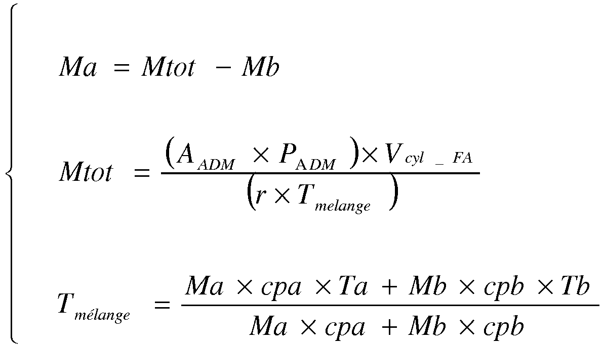
- PADM, Mb, Ma ont déjà été définis précédemment,
- Vcyl_FA est le volume géométrique de la chambre 18 calculé à l'angle FA,
- AADM est un coefficient correcteur,
- r est une constante égale au rapport suivant R/M où R est la constante universelle des gaz parfaits et M est la masse molaire en kg.mol-1 des gaz mélangés,
- Tmélange est la température du mélange d'air frais et de gaz brûlés contenu dans la chambre 18, et
- cpa et cpb sont les capacités calorifiques massiques à pression constante, respectivement, de l'air frais et des gaz brulés, et
- Ta et Tb sont les températures, respectivement, de l'air frais et des gaz brulés. Le volume Vcyl_FA est calculé à l'aide de la relation suivante :

- P ADM , Mb, Ma have already been defined previously,
- V cyl_FA is the geometric volume of the
chamber 18 calculated at the angle FA, - A ADM is a correction coefficient,
- r is a constant equal to the following ratio R / M where R is the universal constant of the ideal gases and M is the molar mass in kg.mol -1 of the mixed gases,
- T mixture is the temperature of the mixture of fresh air and burnt gases contained in the
chamber 18, and - cpa and cpb are the mass heat capacities at constant pressure, respectively, of fresh air and burnt gases, and
- Ta and Tb are the temperatures of fresh air and burnt gases, respectively. The volume V cyl_FA is calculated using the following relation:
Le coefficient correcteur AADM est obtenu à l'aide de la relation suivante : ![]()
- AADM_ATMO est une valeur corrective obtenue à partir d'une cartographie prédéterminée en fonction de l'angle FA et du régime moteur,
- AADM_TURBO est une valeur corrective obtenue à partir d'une cartographie prédéterminée en fonction de l'ange FA et du régime moteur,
- Le coefficient kATMO_TURBO est un coefficient correcteur donné par la relation suivante :

- PATMO est la pression atmosphérique,
- Po est la pression de référence qui est ici égale à 1013 mbar,
- fA(N, FA) est une valeur corrective obtenue à partir d'une cartographie prédéterminée en fonction du régime moteur et de l'angle FA, et
- fB(N) est valeur corrective obtenue à partir d'une cartographie prédéterminée en fonction du régime moteur.
- AADM_ATMO is a corrective value obtained from a predetermined map according to the angle FA and the engine speed,
- AADM_TURBO is a corrective value obtained from a predetermined map according to the angel FA and the engine speed,
- The coefficient kATMO_TURBO is a correction coefficient given by the following relation:
- PATMO is atmospheric pressure,
- Po is the reference pressure which is here equal to 1013 mbar,
- fA (N, FA) is a corrective value obtained from a predetermined map as a function of the engine speed and the angle FA, and
- fB (N) is corrective value obtained from a predetermined map as a function of the engine speed.
La relation définissant la température T mélange est obtenue par un calcul de mélange enthalpique entre la masse de gaz brûlés et la masse d'air frais contenues dans la chambre 18.The relationship defining the temperature T mixture is obtained by a calculation of enthalpy mixture between the mass of burnt gases and the mass of fresh air contained in the
Le système d'équations décrit ci-dessus est un système d'équation à trois inconnus et à trois équations. La résolution de ce système permet d'obtenir des estimations de la masse Ma, de la température Tmélange et de la masse totale Mtot.The system of equations described above is a system of equations with three unknowns and three equations. The resolution of this system makes it possible to obtain estimates of the mass Ma, of the temperature T mixture and of the total mass Mtot.
Plus précisément, l'estimation de la masse Ma est donnée par la relation suivante dans le cas particulier où cpb et cpa sont égaux : ![]()
![]()
Eventuellement, lors de l'étape 128, l'estimation de la masse Ma obtenue après avoir résolu le système d'équations est corrigée en fonction de l'inverse de la température Ta de l'air frais. Par exemple, la masse Ma est corrigée à l'aide de la relation suivante : ![]()
![]()
Enfin, lors d'une étape 130, le module 100 estime le remplissage total rempl_tot en air frais. Ce remplissage total rempl_tot est par exemple obtenu à l'aide de la relation suivante : ![]()
![]()
Pour obtenir cette dernière relation, on a considéré que le gaz balayé de l'admission vers l'échappement pendant le croisement de soupapes remplissait d'abord entièrement le volume de la chambre 18 avant de passer ensuite directement de l'admission vers l'échappement. Ainsi, tant que la masse Mbal_tot de gaz balayés est inférieure à la masse Mb de gaz brulés, on considère qu'il n'y a pas de balayage. A l'inverse, dès que la masse Mbal_tot est supérieure à la masse Mb de gaz brulés, on considère qu'il n'y a plus que du balayage de gaz entre l'admission et l'échappement. La masse Mbal définie au début de cette description correspond uniquement au dernier terme de la relation ci-dessus.To obtain this latter relationship, it was considered that the gas swept from the intake to the exhaust during the crossing of valves first filled the volume of the
Ce qui a été décrit ci-dessus peut également être appliqué à un moteur dépourvu de déphaseur d'arbre à cames à l'admission ou à l'échappement.What has been described above can also be applied to an engine devoid of camshaft phase shifter on intake or exhaust.
Claims (4)
- A method for estimating a total filling rempl_tot with supercharged fresh air of a combustion chamber of an engine cylinder during an engine cycle, including:- the estimation (128) of a mass Ma of fresh air taken into the interior of the combustion chamber of an engine cylinder during an engine cycle, implemented by an electronic computer,- the estimation (128) of a total mass Mtot of gas contained in the combustion chamber at the end of the intake of fresh air, the estimation (120, 124) of a mass Mb of burnt gases contained in the combustion chamber at the end of the exhaust of the burnt gases, and the estimation (128) of the mass Ma of fresh air from the different between the total mass Mtot and the mass Mb of estimated burnt gases, in which the estimation (128) of the total mass Mtot is obtained from an intake pressure PADM of the air, a volume of the combustion chamber at the end of the intake, a temperature Tmélange of the mixture of fresh air and of burnt gases contained in the combustion chamber at the end of the intake of fresh air, and a correction coefficient AADM, the value of which is obtained from a prerecorded cartograpnhy as a function of an angle FA of end of intake and of the engine speed, the estimation of the mass of air Ma of fresh air being a solution of the following system of equations:characterized in that this method includes:
 - AADM is the correction coefficient, the value of which is a function of the engine speed and of the end of intake angle,- PADM is the air intake pressure,- Vcyl_FA is the geometric volume of the combustion chamber calculated at the end of intake angle,- Tmélange is the temperature of the mixture of fresh air and of burnt gases contained in the combustion chamber,- r is a constant equal to the following ratio R/M, where R is the universal constant of the perfect gases and M is the molar mass in kg.mol-1 of the mixed gases,- cpa and cpb are the specific heat capacities at constant pressure, respectively, of the fresh air and of the burnt gases, and- Ta and Tb are the temperatures, respectively, of the fresh air and of the burnt gases,- the estimation (124) of a mass Mbal_tot of swept gases from intake to exhaust on valve overlap,- the estimation (130) of the total filling rempl_tot of supercharged fresh air from the mass of fresh air Ma and the mass Mbal_tot of estimated swept gases,- the control of different actuators, injectors and ignition devices of the engine as a function of the estimations of the mass Ma and of the total filling rempl_tot.
 - The method according to Claim 1, in which the estimation of the mass Mb of burnt gases includes the estimation (120) of a mass Mb_resi of residual burnt gases contained in the combustion chamber at the end of the exhaust of the burnt gases, and the estimation (122) of a mass Mb-reasp of reaspirated burnt gases in the interior of the combustion chamber during the valve overlap.
- The method according to Claim 2, in which the estimation (120) of the mass Mb_resi is obtained from a pressure PECH of the burnt gases, an interior volume of the combustion chamber at the end of the exhaust of the burnt gases, a temperature TECH of the burnt gases and a correction coefficient AECH of the pressure PECH, the value of which is a function of an angle of end of exhaust and of engine speed.
- The method according to one of the preceding claims, in which the estimation (130) of the total filling is a solution of the following equation system:
 - Mtot is the total mass of gas contained in the combustion chamber at the end of intake of fresh air previously defined,- Mo is a reference mass of air in the normal temperature and pressure conditions,- Mb is a mass of burnt gases contained in the combustion chamber at the end of exhaust of the burnt gases,- Mbal_tot is the total mass of swept gases (air and burnt gas) during the valve overlap,- Mbal is the mass of swept gas (air) between intake and exhaust during the valve overlap,- Max (...) and Min (...) are respectively the functions returning the maximum and the minimum, and- |...| is the absolute value.
Applications Claiming Priority (2)
| Application Number | Priority Date | Filing Date | Title |
|---|---|---|---|
| FR0951133A FR2942503B1 (en) | 2009-02-23 | 2009-02-23 | METHOD AND ESTIMATOR OF FRESH AIR MASS IN A COMBUSTION CHAMBER, TOTAL FILLING ESTIMATING METHOD, RECORDING MEDIUM FOR THESE METHODS AND VEHICLE EQUIPPED WITH SAID ESTIMATOR |
| PCT/FR2010/050079 WO2010094870A1 (en) | 2009-02-23 | 2010-01-19 | Method and estimator for a fresh air mass in a combustion chamber, method for estimating total filling, recording medium for said methods, and vehicle provided with such an estimator |
Publications (2)
| Publication Number | Publication Date |
|---|---|
| EP2399015A1 EP2399015A1 (en) | 2011-12-28 |
| EP2399015B1 true EP2399015B1 (en) | 2019-12-18 |
Family
ID=41138749
Family Applications (1)
| Application Number | Title | Priority Date | Filing Date |
|---|---|---|---|
| EP10707320.7A Active EP2399015B1 (en) | 2009-02-23 | 2010-01-19 | Method for estimating total filling of a combustion chamber of an engine |
Country Status (4)
| Country | Link |
|---|---|
| EP (1) | EP2399015B1 (en) |
| FR (1) | FR2942503B1 (en) |
| RU (1) | RU2525862C2 (en) |
| WO (1) | WO2010094870A1 (en) |
Families Citing this family (7)
| Publication number | Priority date | Publication date | Assignee | Title |
|---|---|---|---|---|
| FR2989114B1 (en) * | 2012-04-04 | 2014-04-18 | Peugeot Citroen Automobiles Sa | METHOD FOR CONTROLLING AN INTERNAL COMBUSTION ENGINE, SYSTEM FOR IMPLEMENTING THE METHOD, AND MOTOR VEHICLE EQUIPPED WITH SUCH A SYSTEM |
| FR2991383B1 (en) * | 2012-06-04 | 2015-11-27 | Peugeot Citroen Automobiles Sa | METHOD FOR ESTIMATING THE FRESH AIR CHARGE OF A THERMAL MOTOR BASED ON THE FUEL ETHANOL CONTENT |
| FR2996596B1 (en) * | 2012-10-05 | 2018-04-13 | Psa Automobiles Sa. | METHOD FOR DETERMINING THE MASS OF FRESH AIR ADMITTED INSIDE A COMBUSTION CHAMBER, COMPUTER FOR THIS METHOD AND VEHICLE EQUIPPED WITH SAID COMPUTER |
| FR3046630B1 (en) * | 2016-01-11 | 2018-01-12 | Peugeot Citroen Automobiles Sa | METHOD OF ESTIMATING A FRESH AIR MASS ADMITTED INSIDE A COMBUSTION CHAMBER OF AN INTERNAL COMBUSTION ENGINE WITH VARIABLE VALVE LIFTING |
| FR3057297B1 (en) | 2016-10-10 | 2018-11-09 | Peugeot Citroen Automobiles Sa | METHOD FOR CONTROLLING A VALVE LIFTING OF AN INTERNAL COMBUSTION ENGINE WITH A VARIABLE VALVE LIFTING |
| CN109781427B (en) * | 2018-12-12 | 2020-08-04 | 西安航天动力试验技术研究所 | Reverse rarefied incoming flow simulation device for liquid attitude control engine high-mode test |
| FR3101672B1 (en) | 2019-10-03 | 2022-04-22 | Renault Sas | System and method for determining an air filling pattern in a cylinder of an internal combustion engine of a motor vehicle |
Family Cites Families (9)
| Publication number | Priority date | Publication date | Assignee | Title |
|---|---|---|---|---|
| FR951133A (en) | 1947-07-02 | 1949-10-17 | Advanced device to induce artificial respiration | |
| US4217866A (en) | 1976-11-08 | 1980-08-19 | Nissan Motor Company, Limited | Four-stroke reciprocatory internal combustion engine and method of operating such an engine |
| RU2090771C1 (en) * | 1991-01-14 | 1997-09-20 | Орбитал Энджин Компани | Method of determination of mass of air fed to engine cylinder (version) device for determination of mass of air fed to cylinder and internal combustion engine used for realization of this method |
| DE19750496A1 (en) * | 1997-11-14 | 1999-05-20 | Bosch Gmbh Robert | Method of determining the air induced into an internal combustion engine |
| DE10061428A1 (en) * | 2000-12-09 | 2002-06-27 | Bayerische Motoren Werke Ag | Method for determining the residual gas content in the combustion chamber of a cylinder of a four-stroke internal combustion engine and for determining an ignition angle |
| DE10213138B4 (en) * | 2001-11-20 | 2017-02-16 | Robert Bosch Gmbh | Method, computer program, control and / or regulating device for operating an internal combustion engine |
| DE10254475B3 (en) * | 2002-11-21 | 2004-04-29 | Siemens Ag | Determining fresh air, residual/total gas masses in combustion engine cylinder involves deriving residual, total gas masses from pressures using thermal gas state equation, fresh air from difference |
| FR2879659B1 (en) * | 2004-12-17 | 2007-03-02 | Peugeot Citroen Automobiles Sa | METHOD FOR COMPUTING THE SIMULATION OF THE GAS TRANSFER OF A MOTOR VEHICLE MOTOR |
| ATE413524T1 (en) * | 2006-03-02 | 2008-11-15 | Fiat Ricerche | COMBUSTION ENGINE WITH MEANS FOR DETERMINING FRESH AIR MASS, AND ASSOCIATED METHOD FOR DETERMINING |
-
2009
- 2009-02-23 FR FR0951133A patent/FR2942503B1/en active Active
-
2010
- 2010-01-19 EP EP10707320.7A patent/EP2399015B1/en active Active
- 2010-01-19 RU RU2011138956/07A patent/RU2525862C2/en not_active IP Right Cessation
- 2010-01-19 WO PCT/FR2010/050079 patent/WO2010094870A1/en active Application Filing
Non-Patent Citations (1)
| Title |
|---|
| None * |
Also Published As
| Publication number | Publication date |
|---|---|
| RU2525862C2 (en) | 2014-08-20 |
| FR2942503A1 (en) | 2010-08-27 |
| RU2011138956A (en) | 2013-03-27 |
| FR2942503B1 (en) | 2011-03-04 |
| WO2010094870A1 (en) | 2010-08-26 |
| EP2399015A1 (en) | 2011-12-28 |
Similar Documents
| Publication | Publication Date | Title |
|---|---|---|
| EP2399015B1 (en) | Method for estimating total filling of a combustion chamber of an engine | |
| EP2567086B1 (en) | Method for estimating an amount of fresh air, recording medium and estimator for said method, and vehicle provided with said estimator | |
| FR2787511A1 (en) | METHOD AND DEVICE FOR EQUALIZING THE TORQUES OF EACH CYLINDER OF AN ENGINE | |
| EP2956651B1 (en) | Method of determination of exhaust gas pressure upstream of a turbo charger and of gas flow amount passing through its turbine | |
| WO2010106259A1 (en) | Method for determining the spark advance of a heat engine | |
| EP1952004B1 (en) | Method for estimating the enclosed mass of gases during each operating cycle in the combustion chamber of an internal combustion engine cylinder | |
| EP0522908B1 (en) | Method and system to calculate the mass of air intake in a cylinder of an internal combustion engine | |
| EP2195519B1 (en) | Engine state parameter estimation comprising the measurement of the internal pressure of a cylinder | |
| EP2699778B1 (en) | Fault diagnosis method of supercharged motor and supercharged motor | |
| WO2007010154A2 (en) | Device for detecting in real time the beginning of the combustion phase and corresponding method | |
| FR2835281A1 (en) | Method for estimating mass of air admitted into engine combustion chamber consists of modeling air mass as function of pressure variation in combustion chamber from polytropic gas compression law | |
| WO2014095052A1 (en) | Method for determining the recycled air flow rate and the quantity of oxygen available at the inlet of an internal combustion engine cylinder | |
| FR2996596A1 (en) | Method for determining mass of fresh air contained in gas mixture for internal combustion engine of car, involves determining mass of fresh air by solving system of equations including expressions and temperature of gaseous mixture | |
| FR2909413A1 (en) | Combustion starting instant determining and adjusting method for e.g. oil engine of motor vehicle, involves shifting actual combustion starting instant towards set point starting instant when actual and set point instants are different | |
| FR2833998A1 (en) | I.c. engine recycled exhaust gas mass flow calculation procedure and apparatus uses measurements of pressure and fresh air temperature | |
| FR2527691A1 (en) | METHOD FOR CONTROLLING CONTROL DEVICES OF INTERNAL COMBUSTION ENGINES IMMEDIATELY AFTER THE END OF A FUEL CUT | |
| FR3101672A1 (en) | System and method for determining a pattern of air filling in a cylinder of an internal combustion engine of a motor vehicle | |
| FR2936015A1 (en) | State variables estimation system for diesel engine of vehicle, has multilayer type neuron network for estimating variables of state of engine from tables of intermediate temporal variables | |
| WO2022073729A1 (en) | Method for estimating the pressure in an intake manifold | |
| EP4015808A1 (en) | System and method for controlling an internal combustion engine based on filling performance | |
| FR2950970A3 (en) | Method for estimating average gas target produced by combustion in e.g. petrol engine of motor vehicle, involves deducing balancing coefficients from calculated average value and estimated average torque value based on linear combination | |
| EP4028658A1 (en) | Method for determining the mass of gas enclosed in a combustion chamber | |
| FR2995363A1 (en) | Method for determining mass of fresh air allowed inside combustion chamber of cylinder of thermal engine of motor vehicle, involves determining mass of air by removing total mass of gas mixture from mass of gas flarings and mass of fuel | |
| FR3075269A1 (en) | METHOD FOR DETECTING PRE-IGNITION OF FRESH AIR AND FUEL MIXTURE | |
| FR2933136A3 (en) | Volume estimating method for combustion chamber of variable compression ratio internal combustion engine e.g. petrol engine, of motor vehicle, involves estimating volume of chamber based on rotation angle of crankshaft |
Legal Events
| Date | Code | Title | Description |
|---|---|---|---|
| PUAI | Public reference made under article 153(3) epc to a published international application that has entered the european phase |
Free format text: ORIGINAL CODE: 0009012 |
|
| 17P | Request for examination filed |
Effective date: 20110725 |
|
| AK | Designated contracting states |
Kind code of ref document: A1 Designated state(s): AT BE BG CH CY CZ DE DK EE ES FI FR GB GR HR HU IE IS IT LI LT LU LV MC MK MT NL NO PL PT RO SE SI SK SM TR |
|
| DAX | Request for extension of the european patent (deleted) | ||
| RAP1 | Party data changed (applicant data changed or rights of an application transferred) |
Owner name: PEUGEOT CITROEN AUTOMOBILES SA Owner name: GM GLOBAL TECHNOLOGY OPERATIONS LLC |
|
| RAP1 | Party data changed (applicant data changed or rights of an application transferred) |
Owner name: GM GLOBAL TECHNOLOGY OPERATIONS LLC Owner name: PSA AUTOMOBILES SA |
|
| STAA | Information on the status of an ep patent application or granted ep patent |
Free format text: STATUS: EXAMINATION IS IN PROGRESS |
|
| 17Q | First examination report despatched |
Effective date: 20180222 |
|
| GRAP | Despatch of communication of intention to grant a patent |
Free format text: ORIGINAL CODE: EPIDOSNIGR1 |
|
| STAA | Information on the status of an ep patent application or granted ep patent |
Free format text: STATUS: GRANT OF PATENT IS INTENDED |
|
| INTG | Intention to grant announced |
Effective date: 20190710 |
|
| GRAS | Grant fee paid |
Free format text: ORIGINAL CODE: EPIDOSNIGR3 |
|
| GRAA | (expected) grant |
Free format text: ORIGINAL CODE: 0009210 |
|
| STAA | Information on the status of an ep patent application or granted ep patent |
Free format text: STATUS: THE PATENT HAS BEEN GRANTED |
|
| AK | Designated contracting states |
Kind code of ref document: B1 Designated state(s): AT BE BG CH CY CZ DE DK EE ES FI FR GB GR HR HU IE IS IT LI LT LU LV MC MK MT NL NO PL PT RO SE SI SK SM TR |
|
| REG | Reference to a national code |
Ref country code: GB Ref legal event code: FG4D Free format text: NOT ENGLISH |
|
| REG | Reference to a national code |
Ref country code: CH Ref legal event code: EP |
|
| REG | Reference to a national code |
Ref country code: IE Ref legal event code: FG4D Free format text: LANGUAGE OF EP DOCUMENT: FRENCH |
|
| REG | Reference to a national code |
Ref country code: DE Ref legal event code: R096 Ref document number: 602010062410 Country of ref document: DE |
|
| REG | Reference to a national code |
Ref country code: AT Ref legal event code: REF Ref document number: 1214863 Country of ref document: AT Kind code of ref document: T Effective date: 20200115 |
|
| REG | Reference to a national code |
Ref country code: NL Ref legal event code: MP Effective date: 20191218 |
|
| PG25 | Lapsed in a contracting state [announced via postgrant information from national office to epo] |
Ref country code: LT Free format text: LAPSE BECAUSE OF FAILURE TO SUBMIT A TRANSLATION OF THE DESCRIPTION OR TO PAY THE FEE WITHIN THE PRESCRIBED TIME-LIMIT Effective date: 20191218 Ref country code: NO Free format text: LAPSE BECAUSE OF FAILURE TO SUBMIT A TRANSLATION OF THE DESCRIPTION OR TO PAY THE FEE WITHIN THE PRESCRIBED TIME-LIMIT Effective date: 20200318 Ref country code: GR Free format text: LAPSE BECAUSE OF FAILURE TO SUBMIT A TRANSLATION OF THE DESCRIPTION OR TO PAY THE FEE WITHIN THE PRESCRIBED TIME-LIMIT Effective date: 20200319 Ref country code: BG Free format text: LAPSE BECAUSE OF FAILURE TO SUBMIT A TRANSLATION OF THE DESCRIPTION OR TO PAY THE FEE WITHIN THE PRESCRIBED TIME-LIMIT Effective date: 20200318 Ref country code: FI Free format text: LAPSE BECAUSE OF FAILURE TO SUBMIT A TRANSLATION OF THE DESCRIPTION OR TO PAY THE FEE WITHIN THE PRESCRIBED TIME-LIMIT Effective date: 20191218 Ref country code: LV Free format text: LAPSE BECAUSE OF FAILURE TO SUBMIT A TRANSLATION OF THE DESCRIPTION OR TO PAY THE FEE WITHIN THE PRESCRIBED TIME-LIMIT Effective date: 20191218 Ref country code: SE Free format text: LAPSE BECAUSE OF FAILURE TO SUBMIT A TRANSLATION OF THE DESCRIPTION OR TO PAY THE FEE WITHIN THE PRESCRIBED TIME-LIMIT Effective date: 20191218 |
|
| REG | Reference to a national code |
Ref country code: LT Ref legal event code: MG4D |
|
| PG25 | Lapsed in a contracting state [announced via postgrant information from national office to epo] |
Ref country code: HR Free format text: LAPSE BECAUSE OF FAILURE TO SUBMIT A TRANSLATION OF THE DESCRIPTION OR TO PAY THE FEE WITHIN THE PRESCRIBED TIME-LIMIT Effective date: 20191218 |
|
| PG25 | Lapsed in a contracting state [announced via postgrant information from national office to epo] |
Ref country code: NL Free format text: LAPSE BECAUSE OF FAILURE TO SUBMIT A TRANSLATION OF THE DESCRIPTION OR TO PAY THE FEE WITHIN THE PRESCRIBED TIME-LIMIT Effective date: 20191218 Ref country code: CZ Free format text: LAPSE BECAUSE OF FAILURE TO SUBMIT A TRANSLATION OF THE DESCRIPTION OR TO PAY THE FEE WITHIN THE PRESCRIBED TIME-LIMIT Effective date: 20191218 Ref country code: RO Free format text: LAPSE BECAUSE OF FAILURE TO SUBMIT A TRANSLATION OF THE DESCRIPTION OR TO PAY THE FEE WITHIN THE PRESCRIBED TIME-LIMIT Effective date: 20191218 Ref country code: PT Free format text: LAPSE BECAUSE OF FAILURE TO SUBMIT A TRANSLATION OF THE DESCRIPTION OR TO PAY THE FEE WITHIN THE PRESCRIBED TIME-LIMIT Effective date: 20200513 Ref country code: EE Free format text: LAPSE BECAUSE OF FAILURE TO SUBMIT A TRANSLATION OF THE DESCRIPTION OR TO PAY THE FEE WITHIN THE PRESCRIBED TIME-LIMIT Effective date: 20191218 |
|
| PG25 | Lapsed in a contracting state [announced via postgrant information from national office to epo] |
Ref country code: IS Free format text: LAPSE BECAUSE OF FAILURE TO SUBMIT A TRANSLATION OF THE DESCRIPTION OR TO PAY THE FEE WITHIN THE PRESCRIBED TIME-LIMIT Effective date: 20200418 Ref country code: SK Free format text: LAPSE BECAUSE OF FAILURE TO SUBMIT A TRANSLATION OF THE DESCRIPTION OR TO PAY THE FEE WITHIN THE PRESCRIBED TIME-LIMIT Effective date: 20191218 Ref country code: SM Free format text: LAPSE BECAUSE OF FAILURE TO SUBMIT A TRANSLATION OF THE DESCRIPTION OR TO PAY THE FEE WITHIN THE PRESCRIBED TIME-LIMIT Effective date: 20191218 |
|
| REG | Reference to a national code |
Ref country code: CH Ref legal event code: PL |
|
| REG | Reference to a national code |
Ref country code: DE Ref legal event code: R097 Ref document number: 602010062410 Country of ref document: DE |
|
| PG25 | Lapsed in a contracting state [announced via postgrant information from national office to epo] |
Ref country code: MC Free format text: LAPSE BECAUSE OF FAILURE TO SUBMIT A TRANSLATION OF THE DESCRIPTION OR TO PAY THE FEE WITHIN THE PRESCRIBED TIME-LIMIT Effective date: 20191218 |
|
| REG | Reference to a national code |
Ref country code: AT Ref legal event code: MK05 Ref document number: 1214863 Country of ref document: AT Kind code of ref document: T Effective date: 20191218 Ref country code: BE Ref legal event code: MM Effective date: 20200131 |
|
| PLBE | No opposition filed within time limit |
Free format text: ORIGINAL CODE: 0009261 |
|
| STAA | Information on the status of an ep patent application or granted ep patent |
Free format text: STATUS: NO OPPOSITION FILED WITHIN TIME LIMIT |
|
| PG25 | Lapsed in a contracting state [announced via postgrant information from national office to epo] |
Ref country code: ES Free format text: LAPSE BECAUSE OF FAILURE TO SUBMIT A TRANSLATION OF THE DESCRIPTION OR TO PAY THE FEE WITHIN THE PRESCRIBED TIME-LIMIT Effective date: 20191218 Ref country code: LU Free format text: LAPSE BECAUSE OF NON-PAYMENT OF DUE FEES Effective date: 20200119 Ref country code: DK Free format text: LAPSE BECAUSE OF FAILURE TO SUBMIT A TRANSLATION OF THE DESCRIPTION OR TO PAY THE FEE WITHIN THE PRESCRIBED TIME-LIMIT Effective date: 20191218 |
|
| RAP2 | Party data changed (patent owner data changed or rights of a patent transferred) |
Owner name: PSA AUTOMOBILES SA Owner name: GM GLOBAL TECHNOLOGY OPERATIONS LLC |
|
| 26N | No opposition filed |
Effective date: 20200921 |
|
| PG25 | Lapsed in a contracting state [announced via postgrant information from national office to epo] |
Ref country code: SI Free format text: LAPSE BECAUSE OF FAILURE TO SUBMIT A TRANSLATION OF THE DESCRIPTION OR TO PAY THE FEE WITHIN THE PRESCRIBED TIME-LIMIT Effective date: 20191218 Ref country code: BE Free format text: LAPSE BECAUSE OF NON-PAYMENT OF DUE FEES Effective date: 20200131 Ref country code: LI Free format text: LAPSE BECAUSE OF NON-PAYMENT OF DUE FEES Effective date: 20200131 Ref country code: AT Free format text: LAPSE BECAUSE OF FAILURE TO SUBMIT A TRANSLATION OF THE DESCRIPTION OR TO PAY THE FEE WITHIN THE PRESCRIBED TIME-LIMIT Effective date: 20191218 Ref country code: CH Free format text: LAPSE BECAUSE OF NON-PAYMENT OF DUE FEES Effective date: 20200131 |
|
| PG25 | Lapsed in a contracting state [announced via postgrant information from national office to epo] |
Ref country code: IE Free format text: LAPSE BECAUSE OF NON-PAYMENT OF DUE FEES Effective date: 20200119 Ref country code: IT Free format text: LAPSE BECAUSE OF FAILURE TO SUBMIT A TRANSLATION OF THE DESCRIPTION OR TO PAY THE FEE WITHIN THE PRESCRIBED TIME-LIMIT Effective date: 20191218 |
|
| PG25 | Lapsed in a contracting state [announced via postgrant information from national office to epo] |
Ref country code: PL Free format text: LAPSE BECAUSE OF FAILURE TO SUBMIT A TRANSLATION OF THE DESCRIPTION OR TO PAY THE FEE WITHIN THE PRESCRIBED TIME-LIMIT Effective date: 20191218 |
|
| PGFP | Annual fee paid to national office [announced via postgrant information from national office to epo] |
Ref country code: GB Payment date: 20211216 Year of fee payment: 13 |
|
| PG25 | Lapsed in a contracting state [announced via postgrant information from national office to epo] |
Ref country code: TR Free format text: LAPSE BECAUSE OF FAILURE TO SUBMIT A TRANSLATION OF THE DESCRIPTION OR TO PAY THE FEE WITHIN THE PRESCRIBED TIME-LIMIT Effective date: 20191218 Ref country code: MT Free format text: LAPSE BECAUSE OF FAILURE TO SUBMIT A TRANSLATION OF THE DESCRIPTION OR TO PAY THE FEE WITHIN THE PRESCRIBED TIME-LIMIT Effective date: 20191218 Ref country code: CY Free format text: LAPSE BECAUSE OF FAILURE TO SUBMIT A TRANSLATION OF THE DESCRIPTION OR TO PAY THE FEE WITHIN THE PRESCRIBED TIME-LIMIT Effective date: 20191218 |
|
| PG25 | Lapsed in a contracting state [announced via postgrant information from national office to epo] |
Ref country code: MK Free format text: LAPSE BECAUSE OF FAILURE TO SUBMIT A TRANSLATION OF THE DESCRIPTION OR TO PAY THE FEE WITHIN THE PRESCRIBED TIME-LIMIT Effective date: 20191218 |
|
| PGFP | Annual fee paid to national office [announced via postgrant information from national office to epo] |
Ref country code: DE Payment date: 20221220 Year of fee payment: 14 |
|
| GBPC | Gb: european patent ceased through non-payment of renewal fee |
Effective date: 20230119 |
|
| PG25 | Lapsed in a contracting state [announced via postgrant information from national office to epo] |
Ref country code: GB Free format text: LAPSE BECAUSE OF NON-PAYMENT OF DUE FEES Effective date: 20230119 |
|
| PGFP | Annual fee paid to national office [announced via postgrant information from national office to epo] |
Ref country code: FR Payment date: 20231219 Year of fee payment: 15 |