EP2399007B1 - Nockenwelle - Google Patents
Nockenwelle Download PDFInfo
- Publication number
- EP2399007B1 EP2399007B1 EP10702889.6A EP10702889A EP2399007B1 EP 2399007 B1 EP2399007 B1 EP 2399007B1 EP 10702889 A EP10702889 A EP 10702889A EP 2399007 B1 EP2399007 B1 EP 2399007B1
- Authority
- EP
- European Patent Office
- Prior art keywords
- camshaft
- internal combustion
- securing mechanism
- bearing
- combustion engine
- Prior art date
- Legal status (The legal status is an assumption and is not a legal conclusion. Google has not performed a legal analysis and makes no representation as to the accuracy of the status listed.)
- Not-in-force
Links
- 238000002485 combustion reaction Methods 0.000 claims description 25
- 238000007650 screen-printing Methods 0.000 claims description 6
- 239000011324 bead Substances 0.000 claims description 4
- 239000000463 material Substances 0.000 claims description 4
- 239000000853 adhesive Substances 0.000 claims description 3
- 230000001070 adhesive effect Effects 0.000 claims description 3
- 238000000034 method Methods 0.000 claims 2
- 239000003973 paint Substances 0.000 claims 1
- 238000009434 installation Methods 0.000 description 7
- 239000003921 oil Substances 0.000 description 4
- 238000006243 chemical reaction Methods 0.000 description 3
- 238000004519 manufacturing process Methods 0.000 description 3
- 238000010792 warming Methods 0.000 description 3
- 230000001419 dependent effect Effects 0.000 description 2
- 238000004090 dissolution Methods 0.000 description 2
- 230000000694 effects Effects 0.000 description 2
- 239000010687 lubricating oil Substances 0.000 description 2
- 229920001131 Pulp (paper) Polymers 0.000 description 1
- 230000002411 adverse Effects 0.000 description 1
- 238000004220 aggregation Methods 0.000 description 1
- 230000002776 aggregation Effects 0.000 description 1
- 239000000969 carrier Substances 0.000 description 1
- 239000010724 circulating oil Substances 0.000 description 1
- 239000004519 grease Substances 0.000 description 1
- 238000002955 isolation Methods 0.000 description 1
- 235000015095 lager Nutrition 0.000 description 1
- 230000001050 lubricating effect Effects 0.000 description 1
- 238000005096 rolling process Methods 0.000 description 1
- 239000007787 solid Substances 0.000 description 1
- 238000003860 storage Methods 0.000 description 1
- 239000000126 substance Substances 0.000 description 1
Images
Classifications
-
- F—MECHANICAL ENGINEERING; LIGHTING; HEATING; WEAPONS; BLASTING
- F01—MACHINES OR ENGINES IN GENERAL; ENGINE PLANTS IN GENERAL; STEAM ENGINES
- F01L—CYCLICALLY OPERATING VALVES FOR MACHINES OR ENGINES
- F01L1/00—Valve-gear or valve arrangements, e.g. lift-valve gear
- F01L1/02—Valve drive
- F01L1/04—Valve drive by means of cams, camshafts, cam discs, eccentrics or the like
- F01L1/047—Camshafts
-
- F—MECHANICAL ENGINEERING; LIGHTING; HEATING; WEAPONS; BLASTING
- F16—ENGINEERING ELEMENTS AND UNITS; GENERAL MEASURES FOR PRODUCING AND MAINTAINING EFFECTIVE FUNCTIONING OF MACHINES OR INSTALLATIONS; THERMAL INSULATION IN GENERAL
- F16C—SHAFTS; FLEXIBLE SHAFTS; ELEMENTS OR CRANKSHAFT MECHANISMS; ROTARY BODIES OTHER THAN GEARING ELEMENTS; BEARINGS
- F16C19/00—Bearings with rolling contact, for exclusively rotary movement
- F16C19/22—Bearings with rolling contact, for exclusively rotary movement with bearing rollers essentially of the same size in one or more circular rows, e.g. needle bearings
- F16C19/44—Needle bearings
- F16C19/46—Needle bearings with one row or needles
- F16C19/466—Needle bearings with one row or needles comprising needle rollers and an outer ring, i.e. subunit without inner ring
-
- F—MECHANICAL ENGINEERING; LIGHTING; HEATING; WEAPONS; BLASTING
- F16—ENGINEERING ELEMENTS AND UNITS; GENERAL MEASURES FOR PRODUCING AND MAINTAINING EFFECTIVE FUNCTIONING OF MACHINES OR INSTALLATIONS; THERMAL INSULATION IN GENERAL
- F16C—SHAFTS; FLEXIBLE SHAFTS; ELEMENTS OR CRANKSHAFT MECHANISMS; ROTARY BODIES OTHER THAN GEARING ELEMENTS; BEARINGS
- F16C41/00—Other accessories, e.g. devices integrated in the bearing not relating to the bearing function as such
- F16C41/04—Preventing damage to bearings during storage or transport thereof or when otherwise out of use
-
- F—MECHANICAL ENGINEERING; LIGHTING; HEATING; WEAPONS; BLASTING
- F16—ENGINEERING ELEMENTS AND UNITS; GENERAL MEASURES FOR PRODUCING AND MAINTAINING EFFECTIVE FUNCTIONING OF MACHINES OR INSTALLATIONS; THERMAL INSULATION IN GENERAL
- F16C—SHAFTS; FLEXIBLE SHAFTS; ELEMENTS OR CRANKSHAFT MECHANISMS; ROTARY BODIES OTHER THAN GEARING ELEMENTS; BEARINGS
- F16C2360/00—Engines or pumps
- F16C2360/18—Camshafts
Definitions
- the present invention relates to a camshaft of an internal combustion engine with at least one transport lock.
- the invention also relates to an engine equipped with such a camshaft.
- Camshafts in internal combustion engines are well known and serve to control the opening times of intake and exhaust valves.
- the assembly of a camshaft in a cylinder head of an internal combustion engine is often designed relatively complex, since the camshaft must be aligned before installation.
- the effort for aligning can, for example, be reduced by using transport locks for the delivery of the camshaft to an installation location, which however generally have the disadvantage that they have to be removed again after installation of the camshaft in the cylinder head of the internal combustion engine To ensure proper operation of the camshaft in the internal combustion engine.
- a cam or crankshaft of an internal combustion engine is known, which is mounted with split bearings such that the outer race forming half shells are captively connected to each other and means for axially guiding the bearing assembly are present. This is intended to create a preassembled bearing shaft unit.
- a camshaft is known in which the cam carriers are held in place by an assembly tool during assembly.
- the present invention is concerned with the problem of providing a camshaft an improved embodiment, with which in particular simplifies the assembly of such a camshaft in an associated internal combustion engine.
- the present invention is based on the general idea to use a transport lock for transporting a camshaft, after installation the camshaft does not have to be removed in an internal combustion engine, but can remain on the camshaft and, for example, wears when the internal combustion engine is running in, or dissolves a chemical reaction, thereby creating a clearance.
- the transport lock according to the invention can remain on the camshaft, since it - as mentioned above - during the running-in phase of the internal combustion engine at least as far dissolves or at least so far wears that it no longer affects a clearance of the camshaft.
- the transport lock according to the invention can, for example, from an oil-soluble and / or heat-sensitive material, for example.
- Plastic be designed so that they can reliably take over their security tasks during transport of the camshaft to the factory and by the oil contained in the operation of the engine or the then occurring heat is dissolved, so that the transport lock according to the invention in the simplest possible way, that is without further action, when warming the engine removed or reduced so that it does not obstruct a clearance of the camshaft or a bearing of the same in any way.
- the oil-soluble and / or heat-sensitive transport lock is dissolved or flushed out during warming up of the internal combustion engine circulating oil, but at the same time does not adversely affect the lubricating properties of the oil. It is also conceivable that the at least one oil-soluble or heat-sensitive transport lock is dissolved in such small parts that they remain in the dissolved state completely without negative consequences in the oil or can be deposited on an oil filter device. With the transport lock according to the invention can thus be an installation of the Camshaft significantly simplify in an internal combustion engine, since the transport lock does not have to be removed as usual consuming.
- the at least one transport safety device is produced by screen printing with, in particular, oil-soluble and / or heat-sensitive ink.
- the at least one transport safety device can be designed as an annular or dotted bead printed on an outer lateral surface of the camshaft, whereby production of the at least one transport safety device by screen printing represents a rational and therefore cost-effective and qualitatively extremely high-quality production method.
- the at least one transport safety device is designed as a ring element glued or caulked with the camshaft.
- a connection of the at least one transport lock with the camshaft offers the great advantage that it assumes a solid state of aggregation without the action of heat and without the action of a lubricating oil added during operation of the internal combustion engine, for example, is formed as a manually tangible ring by hand and thereby in the Assembly is extremely easy to handle.
- the warming of the internal combustion engine acting on the at least one transport safety heat or the then acting chemical attack dissolves the at least one transport safety or significantly reduces their wear resistance, so that by mechanical effects, heat and / or chemical reactions, the securing effect of at least one transport safety lifted and thereby a clearance of the camshaft or a bearing is created.
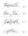
- a camshaft 1 in each case at least one transport lock 2 according to the invention, which, for example, in the region of a cam 3 (see. Fig. 1 and 2 ) and / or in the region of a bearing the camshaft 1 bearing 4 is arranged.
- the transport lock 2 according to the invention of which at least one is provided for each camshaft 1, serves for fixing, in particular for axial fixing of the bearing 4 relative to the camshaft 1.
- the at least one transport lock 2 is designed such that it engages during operation of the internal combustion engine the camshaft 1 is installed, creates a clearance by a wear or a dissolution.
- the at least one transport lock 2 is made of an oil-soluble and / or heat-sensitive material, in particular of such a plastic.
- This offers the great advantage that the transport lock 2 during transport of the camshaft 1 for manufacturing, that is, during an oil-free and relatively cold state, reliably takes over their security tasks, while under the operating conditions, especially during warm-up of the internal combustion engine, by a wear or a dissolution loses.
- the at least one transport lock 2 can now be designed as a ring element glued or caulked to the camshaft 1, as can be seen, for example, in accordance with FIG Fig. 1 is shown. It is also conceivable that the at least one transport lock 2 is connected to the cam 3, in particular adhesively bonded or formed as an axial collar of such a cam 3. Such a condition is, for example, in the Fig. 2 shown. Of course, it is also conceivable that the at least one transport lock connected to the bearing 4, in particular glued to this or molded onto this.
- the at least one transport lock 2 may also be formed as a bead on the camshaft 1, as for example, according to the Fig. 4 is shown.
- the at least one transport lock 2 can be produced, for example, by screen printing with, in particular, oil-soluble and / or heat-sensitive ink.
- Such a transport safety device 2 produced by screen printing can be applied, for example, on an outer circumferential surface of the camshaft 1, on a bearing side surface of the bearing 4, on a bearing inner surface of the bearing 4 or on a side surface of a cam 3.
- the transport lock 2 has an oil-soluble paper pulp and / or is designed as a heat-sensitive adhesive, via which the camshaft 1 is glued in particular with one of the bearings 4 of the camshaft 1.
- the transport lock 2 according to the invention is simple and inexpensive to produce and their backup tasks reliably during transport of the camshaft 1, for example.
- the at least one transport lock 2 can also remain after the installation of the camshaft 1 in the internal combustion engine at this and does not have to be removed consuming as usual.
- the at least one transport lock 2 due to a chemical reaction with the then existing lubricating oil, due to the heat occurring during operation of the internal combustion engine and / or due to mechanical loads dissolved or worn so far that they a free storage of Camshaft in no way stands in the way.
- a rolling bearing grease can also be used for pre-positioning.
Landscapes
- Engineering & Computer Science (AREA)
- General Engineering & Computer Science (AREA)
- Mechanical Engineering (AREA)
- Valve-Gear Or Valve Arrangements (AREA)
Description
- Die vorliegende Erfindung betrifft eine Nockenwelle einer Brennkraftmaschine mit wenigstens einer Transportsicherung. Die Erfindung betrifft außerdem eine mit einer derartigen Nockenwelle ausgestattete Brennkraftmaschine.
- Nockenwellen in Brennkraftmaschinen sind hinlänglich bekannt und dienen zum Steuern der Öffnungszeiten von Ein- und Auslassventilen. Die Montage einer Nockenwelle in einem Zylinderkopf einer Brennkraftmaschine gestaltet sich dabei oftmals relativ aufwändig, da die Nockenwelle vor dem Einbau ausgerichtet werden muss. Der Aufwand zum Ausrichten kann bspw. dadurch reduziert werden, dass zur Anlieferung der Nockenwelle an einen Einbauort Transportsicherungen verwendet werden, welche jedoch generell den Nachteil aufweisen, dass diese nach dem Einbau der Nockenwelle in den Zylinderkopf der Brennkraftmaschine wieder entfernt werden müssen, um so einen einwandfreien Betrieb der Nockenwelle in der Brennkraftmaschine gewährleisten zu können.
- Aus der
DE 198 44 203 A1 ist eine Nocken- oder Kurbelwelle einer Brennkraftmaschine bekannt, die mit geteilten Wälzlagern derart gelagert ist, dass die eine äußere Laufbahn bildenden Halbschalen unverlierbar miteinander verbunden sind und Mittel zur axialen Führung der Lageranordnung vorhanden sind. Dadurch soll eine vormontierte Lager-Welleneinheit geschaffen werden.
Aus derDE102005020236 A1 ist eine Nockenwelle bekannt, bei der die Nockenträger während der Montage von einem Montagewerkzeug an ihrer Stelle gehalten werden. Die vorliegende Erfindung beschäftigt sich mit dem Problem, für eine Nockenwelle eine verbesserte Ausführungsform anzugeben, mit welcher sich insbesondere die Montage einer derartigen Nockenwelle in einer zugehörigen Brennkraftmaschine vereinfacht. - Dieses Problem wird erfindungsgemäß durch die Gegenstände der unabhängigen Ansprüche gelöst. Vorteilhafte Ausführungsformen sind Gegenstand der abhängigen Ansprüche.
- Die vorliegende Erfindung beruht auf dem allgemeinen Gedanken, zum Transport einer Nockenwelle eine Transportsicherung zu verwenden, die nach dem Einbau der Nockenwelle in eine Brennkraftmaschine nicht entfernt werden muss, sondern an der Nockenwelle verbleiben kann und sich beim Einlaufen der Brennkraftmaschine bspw. verschleißt oder eine chemische Reaktion auflöst und dadurch einen Freigang schafft. Im Unterschied zu herkömmlichen Transportsicherungen, welche nach dem Einbau der Nockenwelle in die Brennkraftmaschine aufwändig und dadurch teuer entfernt werden müssen, kann die erfindungsgemäße Transportsicherung an der Nockenwelle verbleiben, da sie sich - wie oben erwähnt - während der Einlaufphase der Brennkraftmaschine zumindest so weit auflöst bzw. zumindest so weit verschleißt, dass sie einen Freigang der Nockenwelle nicht mehr beeinträchtigt. Die erfindungsgemäße Transportsicherung kann bspw. aus einem öllöslichen und/oder wärmeempfindlichen Material, bspw. Kunststoff, ausgebildet sein, so dass sie während des Transports der Nockenwelle zur Fertigungsstätte zuverlässig ihre Sicherungsaufgaben übernehmen kann und durch das beim Betrieb der Brennkraftmaschine befindliche Öl bzw. die dann auftretende Wärme aufgelöst wird, so dass die erfindungsgemäße Transportsicherung auf denkbar einfachste Weise, das heißt ohne weiteres Zutun, beim Warmlaufen der Brennkraftmaschine entfernt bzw. soweit reduziert wird, dass sie einen Freigang der Nockenwelle bzw. eines Lagers derselben in keinster Weise mehr behindert.
- Denkbar ist hier dabei insbesondere, dass die öllösliche und/oder wärmeempfindliche Transportsicherung während des Warmlaufens der Brennkraftmaschine vom darin zirkulierenden Öl aufgelöst bzw. ausgeschwemmt wird, gleichzeitig aber die Schmiereigenschaften des Öls nicht negativ beeinträchtigt. Denkbar ist auch, dass die wenigstens eine öllösliche bzw. wärmeempfindliche Transportsicherung in so kleine Teile aufgelöst wird, dass sie im gelösten Zustand gänzlich ohne negative Folgen im Öl verbleiben oder aber an einer Ölfiltereinrichtung abgeschieden werden kann. Mit der erfindungsgemäßen Transportsicherung lässt sich somit ein Einbau der Nockenwelle in eine Brennkraftmaschine deutlich vereinfachen, da die Transportsicherung nicht wie bisher üblich aufwendig entfernt werden muss.
- Bei einer vorteilhaften Weiterbildung der erfindungsgemäßen Lösung, ist die wenigstens eine Transportsicherung im Siebdruckverfahren mit insbesondere öllöslicher und/oder wärmeempfindlicher Farbe hergestellt. Die wenigstens eine Transportsicherung kann in diesem Fall als auf einer Außenmantelfläche der Nockenwelle aufgedruckter ringförmiger oder gepunkteter Wulst ausgebildet sein, wobei eine Herstellung der wenigstens einen Transportsicherung im Siebdruckverfahren eine einerseits rationelle und damit kostengünstige und andererseits qualitativ äußerst hochwertige Herstellungsweise darstellt.
- Bei einer weiteren vorteilhaften Ausführungsform der erfindungsgemäßen Lösung, ist die wenigstens eine Transportsicherung als mit der Nockenwelle verklebtes oder verstemmtes Ringelement ausgebildet. Ein derartiges Verbinden der wenigstens einen Transportsicherung mit der Nockenwelle bietet den großen Vorteil, dass diese ohne Einwirkung von Wärme und ohne Einwirkung eines erst beim Betrieb der Brennkraftmaschine zugesetzten Schmieröls einen festen Aggregatszustand einnimmt, bspw. als händisch leicht greifbarer Ring ausgebildet ist und dadurch bei der Montage äußerst einfach handzuhaben ist. Die beim Warmlaufen der Brennkraftmaschine auf die wenigstens eine Transportsicherung einwirkende Wärme bzw. der dann einwirkende chemische Angriff löst die wenigstens eine Transportsicherung auf bzw. reduziert deren Verschleißwiderstand signifikant, so dass durch mechanische Einwirkungen, Wärme und/oder chemische Reaktionen die Sicherungswirkung der wenigstens einen Transportsicherung aufgehoben und dadurch ein Freigang der Nockenwelle bzw. eines Lagers geschaffen wird.
- Weitere wichtige Merkmale und Vorteile der Erfindung ergeben sich aus den Unteransprüchen, aus den Zeichnungen und aus der zugehörigen Figurenbeschreibung anhand der Zeichnungen.
- Es versteht sich, dass die vorstehend genannten und die nachstehend noch zu erläuternden Merkmale nicht nur in der jeweils angegebenen Kombination, sondern auch in anderen Kombinationen oder in Alleinstellung verwendbar sind, ohne den Rahmen der vorliegenden Erfindung zu verlassen.
- Bevorzugte Ausführungsbeispiele der Erfindung sind in den Zeichnungen dargestellt und werden in der nachfolgenden Beschreibung näher erläutert, wobei sich gleiche Bezugszeichen auf gleiche oder ähnliche oder funktional gleiche Bauteile beziehen.
- Dabei zeigen, jeweils schematisch,
- Fig. 1
- eine Schnittdarstellung durch eine Nockenwelle mit einer erfindungsgemäßen und als Ring ausgebildeten Transportsicherung,
- Fig. 2
- eine Darstellung wie in
Fig. 1 , wobei jedoch die ringartige Transportsicherung an einen Bund eines Nockens angeformt, insbesondere angespritzt, ist, - Fig. 3
- zwei ringartige Transportsicherungen im Bereich eines Lagers der Nockenwelle,
- Fig. 4
- zwei jeweils als Ringwülste ausgebildete Transportsicherungen.
- Entsprechend den
Fig. 1 bis 4 weist eine Nockenwelle 1 jeweils zumindest eine erfindungsgemäße Transportsicherung 2 auf, welche bspw. im Bereich eines Nockens 3 (vgl.Fig. 1 und 2 ) und/oder im Bereich eines die Nockenwelle 1 lagernden Lagers 4 angeordnet ist. Die erfindungsgemäße Transportsicherung 2, von welchen je Nockenwelle 1 zumindest eine vorhanden ist, dient zur Fixierung, insbesondere zur Axialfixierung des Lagers 4 relativ zur Nockenwelle 1. Erfindungsgemäß ist nun die zumindest eine Transportsicherung 2 derart ausgebildet, dass sie beim Betrieb der Brennkraftmaschine, in welcher die Nockenwelle 1 eingebaut wird, durch ein Verschleißen oder ein sich Auflösen einen Freigang schafft. Dies kann bspw. dadurch erfolgen, dass die wenigstens eine Transportsicherung 2 aus einem öllöslichen und/oder wärmeempfindlichen Material, insbesondere aus einem derartigen Kunststoff, ausgebildet ist. Dies bietet den großen Vorteil, dass die Transportsicherung 2 während des Transports der Nockenwelle 1 zur Fertigung, das heißt während eines ölfreien und vergleichsweise kalten Zustands, zuverlässig ihre Sicherungsaufgaben übernimmt, während sie diese unter den Betriebsbedingungen, insbesondere beim Warmlaufen der Brennkraftmaschine, durch einen Verschleiß oder ein sich Auflösen verliert. - Erfindungsgemäß kann nun die wenigstens eine Transportsicherung 2 als mit der Nockenwelle 1 verklebtes oder verstemmtes Ringelement ausgebildet sein, wie dies bspw. gemäß der
Fig. 1 dargestellt ist. Denkbar ist auch, dass die wenigstens eine Transportsicherung 2 mit dem Nocken 3 verbunden, insbesondere verklebt oder als ein axialer Bund eines derartigen Nockens 3 ausgebildet ist. Ein derartiger Zustand ist bspw. in derFig. 2 gezeigt. Selbstverständlich ist auch denkbar, dass die wenigstens eine Transportsicherung mit dem Lager 4 verbunden, insbesondere mit diesem verklebt oder an dieses angespritzt ist. - Zusätzlich oder alternativ kann die wenigstens eine Transportsicherung 2 auch als Wulst auf der Nockenwelle 1 ausgebildet sein, wie dies bspw. gemäß der
Fig. 4 dargestellt ist. In diesem Fall kann die wenigstens eine Transportsicherung 2 bspw. im Siebdruckverfahren mit insbesondere öllöslicher und/oder wärmeempfindlicher Farbe hergestellt werden. Eine derartige im Siebdruckverfahren hergestellte Transportsicherung 2 kann bspw. auf einer Außenmantelfläche der Nockenwelle 1, auf einer Lagerseitenfläche des Lagers 4, auf einer Lagerinnenfläche des Lagers 4 oder auf einer Seitenfläche eines Nockens 3 aufgebracht sein. - Denkbar ist auch, dass die Transportsicherung 2 einen öllöslichen Papierzellstoff aufweist und/oder als wärmeempfindlicher Kleber ausgebildet ist, über welchen die Nockenwelle 1 insbesondere mit einem der Lager 4 der Nockenwelle 1 verklebt ist.
- Alle gezeigten und beschriebenen Ausführungsformen weisen dabei den großen Vorteil auf, dass die erfindungsgemäße Transportsicherung 2 einfach und kostengünstig herstellbar ist und ihre Sicherungsaufgaben während des Transports der Nockenwelle 1, bspw. zu einem Einbauort in eine Brennkraftmaschine, zuverlässig übernimmt. Durch die spezielle Materialauswahl kann die wenigstens eine Transportsicherung 2 darüber hinaus auch nach dem Einbau der Nockenwelle 1 in die Brennkraftmaschine an dieser verbleiben und muss nicht wie bisher üblich aufwendig entfernt werden. Während der Warmlaufphase der Brennkraftmaschine wird nun die wenigstens eine Transportsicherung 2 aufgrund einer chemischen Reaktion mit dem dann vorhandenen Schmieröl, aufgrund der beim Betrieb der Brennkraftmaschine auftretenden Wärme und/oder aufgrund von mechanischen Belastungen soweit aufgelöst bzw. verschlissen, dass sie einer freigängigen Lagerung der Nockenwelle in keinster Weise mehr im Wege steht. Theoretisch kann dabei auch ein Wälzlagerfett zur Vorpositionierung verwendet werden.
Claims (9)
- Nockenwelle (1) einer Brennkraftmaschine mit wenigstens einer Transportsicherung (2) zur axialen Fixierung eines Lagers (4), dadurch gekennzeichnet,dass die Transportsicherung (2) aus einem öllöslichen und/oder wärmeempfindlichen Material ausgebildet ist und sich dadurch während der Einlaufphase der Brennkraftmaschine zumindest so weit auflöst bzw. zumindest so weit verschleißt, dass sie einen Freigang der Nockenwelle nicht mehr beeinträchtigt und dadurch nicht entfernt werden muss.
- Nockenwelle nach Anspruch 1,dadurch gekennzeichnet,dass die wenigstens eine Transportsicherung (2) als mit der Nockenwelle (1) verklebtes oder verstemmtes Ringelement ausgebildet ist.
- Nockenwelle nach Anspruch 1,dadurch gekennzeichnet,dass die wenigstens eine Transportsicherung (2) als Wulst auf der Nockenwelle (1) ausgebildet ist.
- Nockenwelle nach einem der Ansprüche 1 bis 3,dadurch gekennzeichnet,dass die wenigstens eine Transportsicherung (2) mit einem Nocken (3) verbunden, insbesondere verklebt oder als axialer Bund eines Nockens (3) ausgebildet ist.
- Nockenwelle nach einem der Ansprüche 1 bis 4,
dadurch gekennzeichnet,
dass die wenigstens eine Transportsicherung (2) aus Kunststoff, insbesondere aus einem öllöslichen und/oder wärmeempfindlichen Kunststoff ausgebildet ist und sich beim Betrieb der Brennkraftmaschine auflöst. - Nockenwelle nach einem der Ansprüche 1 bis 4,
dadurch gekennzeichnet,
dass die wenigstens eine Transportsicherung (2) im Siebdruckverfahren mit insbesondere öllöslicher und/oder wärmeempfindlicher Farbe hergestellt ist. - Nockenwelle nach Anspruch 6,
dadurch gekennzeichnet,
dass die im Siebdruckverfahren hergestellte Transportsicherung (2) auf einer Außenmantelfläche der Nockenwelle (1), auf einer Lagerseitenfläche eines Lagers (4) der Nockenwelle (1), auf einer Lagerinnenfläche des Lagers (4) der Nockenwelle (1) oder auf einer Seitenfläche eines Nockens (3) aufgebracht ist. - Nockenwelle nach einem der Ansprüche 1 bis 4,
dadurch gekennzeichnet,
dass die wenigstens eine Transportsicherung (2) als öllöslicher Papierzellstoff aufweisender und/oder wärmeempfindlicher Kleber ausgebildet ist, über welchen die Nockenwelle (1) insbesondere mit einem Lager (4) verklebt ist. - Brennkraftmaschine mit einer Nockenwelle (1) nach einem der Ansprüche 1 bis 8.
Applications Claiming Priority (2)
| Application Number | Priority Date | Filing Date | Title |
|---|---|---|---|
| DE102009009664A DE102009009664A1 (de) | 2009-02-19 | 2009-02-19 | Nockenwelle |
| PCT/EP2010/051614 WO2010094601A1 (de) | 2009-02-19 | 2010-02-10 | Nockenwelle |
Publications (2)
| Publication Number | Publication Date |
|---|---|
| EP2399007A1 EP2399007A1 (de) | 2011-12-28 |
| EP2399007B1 true EP2399007B1 (de) | 2014-10-29 |
Family
ID=42104538
Family Applications (1)
| Application Number | Title | Priority Date | Filing Date |
|---|---|---|---|
| EP10702889.6A Not-in-force EP2399007B1 (de) | 2009-02-19 | 2010-02-10 | Nockenwelle |
Country Status (5)
| Country | Link |
|---|---|
| US (1) | US8573172B2 (de) |
| EP (1) | EP2399007B1 (de) |
| JP (1) | JP2012518122A (de) |
| DE (1) | DE102009009664A1 (de) |
| WO (1) | WO2010094601A1 (de) |
Families Citing this family (7)
| Publication number | Priority date | Publication date | Assignee | Title |
|---|---|---|---|---|
| FR2979064A1 (fr) * | 2011-08-18 | 2013-02-22 | Peugeot Citroen Automobiles Sa | Procede de revetement d'une came de distribution |
| DE102011088603A1 (de) | 2011-12-14 | 2013-06-20 | Mahle International Gmbh | Welle-/Lageranordnung |
| US9091187B2 (en) * | 2013-02-04 | 2015-07-28 | GM Global Technology Operations LLC | Stationary hydraulic lash adjuster and roller finger follower assembly clip, and method thereof |
| DE102013003294B4 (de) | 2013-02-26 | 2020-04-23 | Thyssenkrupp Presta Teccenter Ag | Welle mit zwei Sicherungsringen zur axialen Fixierung eines Lagers |
| DE102013203842A1 (de) * | 2013-03-06 | 2014-09-11 | Mahle International Gmbh | Lageranordnung |
| DE102014110674A1 (de) | 2014-07-29 | 2016-02-04 | Thyssenkrupp Presta Teccenter Ag | Verfahren zur Einstellung eines Axialspiels zwischen zwei Komponenten einer Nockenweelle |
| DE102016203654A1 (de) | 2016-03-07 | 2017-09-07 | Mahle International Gmbh | Verfahren zur Herstellung einer Lagerbaugruppe |
Family Cites Families (19)
| Publication number | Priority date | Publication date | Assignee | Title |
|---|---|---|---|---|
| DE3445715A1 (de) * | 1984-12-14 | 1986-06-19 | Loctite Deutschland GmbH, 8000 München | Verfahren zum erstellen einer dichtung auf einer dichtflaeche eines bauteils |
| JPS626772A (ja) * | 1985-07-03 | 1987-01-13 | Nippon Piston Ring Co Ltd | カムシヤフトの製造方法 |
| US4667969A (en) * | 1986-07-30 | 1987-05-26 | Klinger, A.G. Zug | Packing materials for shaft seals |
| DE3643673A1 (de) | 1986-12-20 | 1988-06-30 | Porsche Ag | Nockenwelle fuer eine brennkraftmaschine |
| JPS6477706A (en) * | 1987-09-18 | 1989-03-23 | Hitachi Metals Ltd | Chip member for locker arm |
| GB2277361B (en) * | 1993-04-21 | 1995-11-08 | T & N Technology Ltd | Manufacture of camshafts |
| FR2706565B1 (fr) * | 1993-06-14 | 1995-09-01 | Piv Sa | Joint d'étanchéité pour arbre tournant. |
| DE19503699A1 (de) * | 1995-02-04 | 1996-08-08 | Schaeffler Waelzlager Kg | Hydraulischer Ventiltriebsstößel |
| US6171070B1 (en) * | 1997-05-09 | 2001-01-09 | Hakusu Tech Co., Ltd. | High-pressure reciprocating pumps |
| DE19844203A1 (de) * | 1998-09-26 | 2000-03-30 | Schaeffler Waelzlager Ohg | Lagerung einer Welle einer Brennkraftmaschine mit geteilten Wälzlagern |
| JP4234953B2 (ja) * | 2002-06-06 | 2009-03-04 | 株式会社オティックス | 複合カムシャフト及びその製造方法 |
| DE10302876A1 (de) * | 2003-01-25 | 2004-08-05 | Ina-Schaeffler Kg | Baueinheit mit einer Hülse für Kettensteuertriebe |
| DE602006020117D1 (de) | 2005-03-14 | 2011-03-31 | Honda Motor Co Ltd | Nadellager und herstellungsverfahren dafür |
| DE102005020236B4 (de) | 2005-04-30 | 2016-02-25 | Audi Ag | Verfahren zur Montage einer Nockenwelle am Zylinderkopf einer Brennkraftmaschine |
| DE102005062207A1 (de) * | 2005-12-24 | 2007-06-28 | Mahle International Gmbh | Nockenwelle |
| JP4544162B2 (ja) * | 2006-01-18 | 2010-09-15 | 日産自動車株式会社 | 動弁装置のラッシュアジャスタ |
| DE102006008532A1 (de) * | 2006-02-22 | 2007-08-30 | Thyssenkrupp Automotive Ag | Verfahren und Vorrichtung zur Fertigbearbeitung von gebauten Nocken- und Exzenterwellen |
| DE102007024092A1 (de) * | 2007-05-22 | 2008-11-27 | Mahle International Gmbh | Nockenwelle |
| DE102007024736B3 (de) | 2007-05-25 | 2008-06-12 | Neumeister Hydraulik Gmbh | Verriegelungszylinder mit Fluidgleitlagerung |
-
2009
- 2009-02-19 DE DE102009009664A patent/DE102009009664A1/de not_active Withdrawn
-
2010
- 2010-02-10 US US13/202,258 patent/US8573172B2/en not_active Expired - Fee Related
- 2010-02-10 WO PCT/EP2010/051614 patent/WO2010094601A1/de not_active Ceased
- 2010-02-10 JP JP2011550519A patent/JP2012518122A/ja active Pending
- 2010-02-10 EP EP10702889.6A patent/EP2399007B1/de not_active Not-in-force
Also Published As
| Publication number | Publication date |
|---|---|
| JP2012518122A (ja) | 2012-08-09 |
| US20120037103A1 (en) | 2012-02-16 |
| US8573172B2 (en) | 2013-11-05 |
| WO2010094601A1 (de) | 2010-08-26 |
| EP2399007A1 (de) | 2011-12-28 |
| DE102009009664A1 (de) | 2010-08-26 |
Similar Documents
| Publication | Publication Date | Title |
|---|---|---|
| EP1995417B1 (de) | Nockenwelle | |
| EP2399007A1 (de) | Nockenwelle | |
| DE102009000915A1 (de) | Hybridantrieb für ein Kraftfahrzeug | |
| EP2225452A1 (de) | Zylinderkopfhaube | |
| EP1963625B1 (de) | Nockenwelle | |
| WO2012104242A1 (de) | Vorrichtung zur veränderung der relativen winkellage einer nockenwelle gegenüber einer kurbelwelle einer brennkraftmaschine | |
| DE102016214261A1 (de) | Verfahren zur Herstellung einer Riemenscheibenvorrichtung, Riemenscheibenvorrichtung gemäß einem solchen Herstellungsverfahren und mit einer solchen Riemenscheibe ausgestatteter Motor | |
| DE102010061012B4 (de) | Ventilzeitsteuervorrichtung | |
| DE102013205129A1 (de) | Lagerrahmen oder Zylinderkopfhaube einer Brennkraftmaschine | |
| WO2008122653A1 (de) | Nocken für eine nocken- oder steuerwelle | |
| DE102008049696A1 (de) | Anlasservorrichtung für Maschinen | |
| DE102014110674A1 (de) | Verfahren zur Einstellung eines Axialspiels zwischen zwei Komponenten einer Nockenweelle | |
| DE102011078434A1 (de) | Lagerung einer Nockenwelle mittels Wälzlagern | |
| DE102015224011A1 (de) | Verstellbare Nockenwelle | |
| EP2966314A1 (de) | Schwungrad eines verbrennungsmotors mit einem mehrteiligen zahnkranz, der ein mit einem verzahnungsabschnitt versehenes segment aufweist | |
| WO2015154757A1 (de) | Hubübertragungsbauteil | |
| DE102014102100A1 (de) | Mechanischer Stößel | |
| DE102009049218A1 (de) | Nockenwelle für eine Brennkraftmaschine | |
| EP3165721A1 (de) | Nockenwelle | |
| EP2808506A1 (de) | Ölfilter/Ölmodul | |
| DE10322250A1 (de) | System mit Hilfsnockenwelle und mindestens zwei Lagern und Verfahren zur Herstellung eines Systems mit Hilfsnockenwelle und mindestens zwei Lagern | |
| DE102011083134A1 (de) | Pleuel | |
| DE102011000591A1 (de) | Zentralventil | |
| DE102010019131A1 (de) | Brennkraftmaschine | |
| DE102016217146A1 (de) | Variable Nockenwellensteuerung |
Legal Events
| Date | Code | Title | Description |
|---|---|---|---|
| PUAI | Public reference made under article 153(3) epc to a published international application that has entered the european phase |
Free format text: ORIGINAL CODE: 0009012 |
|
| 17P | Request for examination filed |
Effective date: 20110805 |
|
| AK | Designated contracting states |
Kind code of ref document: A1 Designated state(s): AT BE BG CH CY CZ DE DK EE ES FI FR GB GR HR HU IE IS IT LI LT LU LV MC MK MT NL NO PL PT RO SE SI SK SM TR |
|
| DAX | Request for extension of the european patent (deleted) | ||
| GRAP | Despatch of communication of intention to grant a patent |
Free format text: ORIGINAL CODE: EPIDOSNIGR1 |
|
| INTG | Intention to grant announced |
Effective date: 20140730 |
|
| GRAS | Grant fee paid |
Free format text: ORIGINAL CODE: EPIDOSNIGR3 |
|
| GRAA | (expected) grant |
Free format text: ORIGINAL CODE: 0009210 |
|
| AK | Designated contracting states |
Kind code of ref document: B1 Designated state(s): AT BE BG CH CY CZ DE DK EE ES FI FR GB GR HR HU IE IS IT LI LT LU LV MC MK MT NL NO PL PT RO SE SI SK SM TR |
|
| REG | Reference to a national code |
Ref country code: GB Ref legal event code: FG4D Free format text: NOT ENGLISH |
|
| REG | Reference to a national code |
Ref country code: CH Ref legal event code: EP |
|
| REG | Reference to a national code |
Ref country code: AT Ref legal event code: REF Ref document number: 693727 Country of ref document: AT Kind code of ref document: T Effective date: 20141115 |
|
| REG | Reference to a national code |
Ref country code: IE Ref legal event code: FG4D Free format text: LANGUAGE OF EP DOCUMENT: GERMAN |
|
| REG | Reference to a national code |
Ref country code: DE Ref legal event code: R083 Ref document number: 502010008138 Country of ref document: DE |
|
| REG | Reference to a national code |
Ref country code: DE Ref legal event code: R096 Ref document number: 502010008138 Country of ref document: DE Effective date: 20141211 |
|
| REG | Reference to a national code |
Ref country code: NL Ref legal event code: VDEP Effective date: 20141029 |
|
| REG | Reference to a national code |
Ref country code: LT Ref legal event code: MG4D |
|
| PG25 | Lapsed in a contracting state [announced via postgrant information from national office to epo] |
Ref country code: NO Free format text: LAPSE BECAUSE OF FAILURE TO SUBMIT A TRANSLATION OF THE DESCRIPTION OR TO PAY THE FEE WITHIN THE PRESCRIBED TIME-LIMIT Effective date: 20150129 Ref country code: NL Free format text: LAPSE BECAUSE OF FAILURE TO SUBMIT A TRANSLATION OF THE DESCRIPTION OR TO PAY THE FEE WITHIN THE PRESCRIBED TIME-LIMIT Effective date: 20141029 Ref country code: LT Free format text: LAPSE BECAUSE OF FAILURE TO SUBMIT A TRANSLATION OF THE DESCRIPTION OR TO PAY THE FEE WITHIN THE PRESCRIBED TIME-LIMIT Effective date: 20141029 Ref country code: IS Free format text: LAPSE BECAUSE OF FAILURE TO SUBMIT A TRANSLATION OF THE DESCRIPTION OR TO PAY THE FEE WITHIN THE PRESCRIBED TIME-LIMIT Effective date: 20150228 Ref country code: PT Free format text: LAPSE BECAUSE OF FAILURE TO SUBMIT A TRANSLATION OF THE DESCRIPTION OR TO PAY THE FEE WITHIN THE PRESCRIBED TIME-LIMIT Effective date: 20150302 Ref country code: ES Free format text: LAPSE BECAUSE OF FAILURE TO SUBMIT A TRANSLATION OF THE DESCRIPTION OR TO PAY THE FEE WITHIN THE PRESCRIBED TIME-LIMIT Effective date: 20141029 Ref country code: FI Free format text: LAPSE BECAUSE OF FAILURE TO SUBMIT A TRANSLATION OF THE DESCRIPTION OR TO PAY THE FEE WITHIN THE PRESCRIBED TIME-LIMIT Effective date: 20141029 |
|
| PG25 | Lapsed in a contracting state [announced via postgrant information from national office to epo] |
Ref country code: LV Free format text: LAPSE BECAUSE OF FAILURE TO SUBMIT A TRANSLATION OF THE DESCRIPTION OR TO PAY THE FEE WITHIN THE PRESCRIBED TIME-LIMIT Effective date: 20141029 Ref country code: SE Free format text: LAPSE BECAUSE OF FAILURE TO SUBMIT A TRANSLATION OF THE DESCRIPTION OR TO PAY THE FEE WITHIN THE PRESCRIBED TIME-LIMIT Effective date: 20141029 Ref country code: CY Free format text: LAPSE BECAUSE OF FAILURE TO SUBMIT A TRANSLATION OF THE DESCRIPTION OR TO PAY THE FEE WITHIN THE PRESCRIBED TIME-LIMIT Effective date: 20141029 Ref country code: PL Free format text: LAPSE BECAUSE OF FAILURE TO SUBMIT A TRANSLATION OF THE DESCRIPTION OR TO PAY THE FEE WITHIN THE PRESCRIBED TIME-LIMIT Effective date: 20141029 Ref country code: GR Free format text: LAPSE BECAUSE OF FAILURE TO SUBMIT A TRANSLATION OF THE DESCRIPTION OR TO PAY THE FEE WITHIN THE PRESCRIBED TIME-LIMIT Effective date: 20150130 Ref country code: HR Free format text: LAPSE BECAUSE OF FAILURE TO SUBMIT A TRANSLATION OF THE DESCRIPTION OR TO PAY THE FEE WITHIN THE PRESCRIBED TIME-LIMIT Effective date: 20141029 |
|
| REG | Reference to a national code |
Ref country code: DE Ref legal event code: R097 Ref document number: 502010008138 Country of ref document: DE |
|
| PG25 | Lapsed in a contracting state [announced via postgrant information from national office to epo] |
Ref country code: CZ Free format text: LAPSE BECAUSE OF FAILURE TO SUBMIT A TRANSLATION OF THE DESCRIPTION OR TO PAY THE FEE WITHIN THE PRESCRIBED TIME-LIMIT Effective date: 20141029 Ref country code: SK Free format text: LAPSE BECAUSE OF FAILURE TO SUBMIT A TRANSLATION OF THE DESCRIPTION OR TO PAY THE FEE WITHIN THE PRESCRIBED TIME-LIMIT Effective date: 20141029 Ref country code: DK Free format text: LAPSE BECAUSE OF FAILURE TO SUBMIT A TRANSLATION OF THE DESCRIPTION OR TO PAY THE FEE WITHIN THE PRESCRIBED TIME-LIMIT Effective date: 20141029 Ref country code: RO Free format text: LAPSE BECAUSE OF FAILURE TO SUBMIT A TRANSLATION OF THE DESCRIPTION OR TO PAY THE FEE WITHIN THE PRESCRIBED TIME-LIMIT Effective date: 20141029 Ref country code: EE Free format text: LAPSE BECAUSE OF FAILURE TO SUBMIT A TRANSLATION OF THE DESCRIPTION OR TO PAY THE FEE WITHIN THE PRESCRIBED TIME-LIMIT Effective date: 20141029 |
|
| PG25 | Lapsed in a contracting state [announced via postgrant information from national office to epo] |
Ref country code: IT Free format text: LAPSE BECAUSE OF FAILURE TO SUBMIT A TRANSLATION OF THE DESCRIPTION OR TO PAY THE FEE WITHIN THE PRESCRIBED TIME-LIMIT Effective date: 20141029 |
|
| PLBE | No opposition filed within time limit |
Free format text: ORIGINAL CODE: 0009261 |
|
| STAA | Information on the status of an ep patent application or granted ep patent |
Free format text: STATUS: NO OPPOSITION FILED WITHIN TIME LIMIT |
|
| PG25 | Lapsed in a contracting state [announced via postgrant information from national office to epo] |
Ref country code: LU Free format text: LAPSE BECAUSE OF FAILURE TO SUBMIT A TRANSLATION OF THE DESCRIPTION OR TO PAY THE FEE WITHIN THE PRESCRIBED TIME-LIMIT Effective date: 20150210 |
|
| REG | Reference to a national code |
Ref country code: CH Ref legal event code: PL |
|
| 26N | No opposition filed |
Effective date: 20150730 |
|
| PG25 | Lapsed in a contracting state [announced via postgrant information from national office to epo] |
Ref country code: MC Free format text: LAPSE BECAUSE OF FAILURE TO SUBMIT A TRANSLATION OF THE DESCRIPTION OR TO PAY THE FEE WITHIN THE PRESCRIBED TIME-LIMIT Effective date: 20141029 Ref country code: CH Free format text: LAPSE BECAUSE OF NON-PAYMENT OF DUE FEES Effective date: 20150228 Ref country code: LI Free format text: LAPSE BECAUSE OF NON-PAYMENT OF DUE FEES Effective date: 20150228 |
|
| REG | Reference to a national code |
Ref country code: IE Ref legal event code: MM4A |
|
| PG25 | Lapsed in a contracting state [announced via postgrant information from national office to epo] |
Ref country code: IE Free format text: LAPSE BECAUSE OF NON-PAYMENT OF DUE FEES Effective date: 20150210 |
|
| PG25 | Lapsed in a contracting state [announced via postgrant information from national office to epo] |
Ref country code: SI Free format text: LAPSE BECAUSE OF FAILURE TO SUBMIT A TRANSLATION OF THE DESCRIPTION OR TO PAY THE FEE WITHIN THE PRESCRIBED TIME-LIMIT Effective date: 20141029 |
|
| REG | Reference to a national code |
Ref country code: FR Ref legal event code: PLFP Year of fee payment: 7 |
|
| REG | Reference to a national code |
Ref country code: AT Ref legal event code: MM01 Ref document number: 693727 Country of ref document: AT Kind code of ref document: T Effective date: 20150210 |
|
| PG25 | Lapsed in a contracting state [announced via postgrant information from national office to epo] |
Ref country code: AT Free format text: LAPSE BECAUSE OF NON-PAYMENT OF DUE FEES Effective date: 20150210 |
|
| PG25 | Lapsed in a contracting state [announced via postgrant information from national office to epo] |
Ref country code: MT Free format text: LAPSE BECAUSE OF FAILURE TO SUBMIT A TRANSLATION OF THE DESCRIPTION OR TO PAY THE FEE WITHIN THE PRESCRIBED TIME-LIMIT Effective date: 20141029 |
|
| REG | Reference to a national code |
Ref country code: FR Ref legal event code: PLFP Year of fee payment: 8 |
|
| PG25 | Lapsed in a contracting state [announced via postgrant information from national office to epo] |
Ref country code: HU Free format text: LAPSE BECAUSE OF FAILURE TO SUBMIT A TRANSLATION OF THE DESCRIPTION OR TO PAY THE FEE WITHIN THE PRESCRIBED TIME-LIMIT; INVALID AB INITIO Effective date: 20100210 Ref country code: BG Free format text: LAPSE BECAUSE OF FAILURE TO SUBMIT A TRANSLATION OF THE DESCRIPTION OR TO PAY THE FEE WITHIN THE PRESCRIBED TIME-LIMIT Effective date: 20141029 Ref country code: SM Free format text: LAPSE BECAUSE OF FAILURE TO SUBMIT A TRANSLATION OF THE DESCRIPTION OR TO PAY THE FEE WITHIN THE PRESCRIBED TIME-LIMIT Effective date: 20141029 |
|
| PG25 | Lapsed in a contracting state [announced via postgrant information from national office to epo] |
Ref country code: BE Free format text: LAPSE BECAUSE OF NON-PAYMENT OF DUE FEES Effective date: 20150228 |
|
| PG25 | Lapsed in a contracting state [announced via postgrant information from national office to epo] |
Ref country code: TR Free format text: LAPSE BECAUSE OF FAILURE TO SUBMIT A TRANSLATION OF THE DESCRIPTION OR TO PAY THE FEE WITHIN THE PRESCRIBED TIME-LIMIT Effective date: 20141029 |
|
| REG | Reference to a national code |
Ref country code: FR Ref legal event code: PLFP Year of fee payment: 9 |
|
| PG25 | Lapsed in a contracting state [announced via postgrant information from national office to epo] |
Ref country code: MK Free format text: LAPSE BECAUSE OF FAILURE TO SUBMIT A TRANSLATION OF THE DESCRIPTION OR TO PAY THE FEE WITHIN THE PRESCRIBED TIME-LIMIT Effective date: 20141029 |
|
| PGFP | Annual fee paid to national office [announced via postgrant information from national office to epo] |
Ref country code: GB Payment date: 20200226 Year of fee payment: 11 |
|
| PGFP | Annual fee paid to national office [announced via postgrant information from national office to epo] |
Ref country code: FR Payment date: 20200225 Year of fee payment: 11 |
|
| GBPC | Gb: european patent ceased through non-payment of renewal fee |
Effective date: 20210210 |
|
| PG25 | Lapsed in a contracting state [announced via postgrant information from national office to epo] |
Ref country code: FR Free format text: LAPSE BECAUSE OF NON-PAYMENT OF DUE FEES Effective date: 20210228 Ref country code: GB Free format text: LAPSE BECAUSE OF NON-PAYMENT OF DUE FEES Effective date: 20210210 |
|
| PGFP | Annual fee paid to national office [announced via postgrant information from national office to epo] |
Ref country code: DE Payment date: 20220225 Year of fee payment: 13 |
|
| REG | Reference to a national code |
Ref country code: DE Ref legal event code: R119 Ref document number: 502010008138 Country of ref document: DE |
|
| PG25 | Lapsed in a contracting state [announced via postgrant information from national office to epo] |
Ref country code: DE Free format text: LAPSE BECAUSE OF NON-PAYMENT OF DUE FEES Effective date: 20230901 |