EP2398973B1 - A framing system - Google Patents
A framing system Download PDFInfo
- Publication number
- EP2398973B1 EP2398973B1 EP10705438.9A EP10705438A EP2398973B1 EP 2398973 B1 EP2398973 B1 EP 2398973B1 EP 10705438 A EP10705438 A EP 10705438A EP 2398973 B1 EP2398973 B1 EP 2398973B1
- Authority
- EP
- European Patent Office
- Prior art keywords
- stud
- header
- web
- studs
- framing system
- Prior art date
- Legal status (The legal status is an assumption and is not a legal conclusion. Google has not performed a legal analysis and makes no representation as to the accuracy of the status listed.)
- Active
Links
- 238000009432 framing Methods 0.000 title claims description 48
- 238000000034 method Methods 0.000 claims description 2
- 229910052751 metal Inorganic materials 0.000 description 6
- 239000002184 metal Substances 0.000 description 5
- 238000010276 construction Methods 0.000 description 4
- 229910000831 Steel Inorganic materials 0.000 description 2
- 238000005253 cladding Methods 0.000 description 2
- 230000000694 effects Effects 0.000 description 2
- 238000009434 installation Methods 0.000 description 2
- 239000003550 marker Substances 0.000 description 2
- 238000010079 rubber tapping Methods 0.000 description 2
- 239000010959 steel Substances 0.000 description 2
- 238000009435 building construction Methods 0.000 description 1
- 238000004519 manufacturing process Methods 0.000 description 1
- 238000005192 partition Methods 0.000 description 1
- 239000000758 substrate Substances 0.000 description 1
Images


Classifications
-
- E—FIXED CONSTRUCTIONS
- E04—BUILDING
- E04B—GENERAL BUILDING CONSTRUCTIONS; WALLS, e.g. PARTITIONS; ROOFS; FLOORS; CEILINGS; INSULATION OR OTHER PROTECTION OF BUILDINGS
- E04B2/00—Walls, e.g. partitions, for buildings; Wall construction with regard to insulation; Connections specially adapted to walls
- E04B2/74—Removable non-load-bearing partitions; Partitions with a free upper edge
- E04B2/76—Removable non-load-bearing partitions; Partitions with a free upper edge with framework or posts of metal
- E04B2/766—T-connections
- E04B2/767—Connections between wall studs and upper or lower locating rails
- E04B2/768—Connections between wall studs and upper or lower locating rails allowing vertical movement of upper rail with respect to the stud, e.g. by using slots in the rail or stud
-
- E—FIXED CONSTRUCTIONS
- E04—BUILDING
- E04B—GENERAL BUILDING CONSTRUCTIONS; WALLS, e.g. PARTITIONS; ROOFS; FLOORS; CEILINGS; INSULATION OR OTHER PROTECTION OF BUILDINGS
- E04B2/00—Walls, e.g. partitions, for buildings; Wall construction with regard to insulation; Connections specially adapted to walls
- E04B2/74—Removable non-load-bearing partitions; Partitions with a free upper edge
- E04B2/82—Removable non-load-bearing partitions; Partitions with a free upper edge characterised by the manner in which edges are connected to the building; Means therefor; Special details of easily-removable partitions as far as related to the connection with other parts of the building
- E04B2/821—Connections between two opposed surfaces (i.e. floor and ceiling) by means of a device offering a restraining force acting in the plane of the partition
Definitions
- This invention relates to a framing system of the type comprising a plurality of studs and a header track for the studs, the studs and header track having adjustment means to accommodate movement of the header relative to the studs.
- a framing system comprises a number of roll formed metal elements jointed together. Such a framing system may be used to provide a wall such as a partition wall of a building such as a modular building.
- Many framing systems of this type are known. There is however a need for an improved system which will be easy to assembly whilst restricting tolerances and thereby ensuring greater accuracy in overall dimensions. Another issue associated with known systems of this type is that they are relatively expensive to manufacture and are of relatively complex construction.
- US-A-3 845 601 describes a metal wall framing system for building construction wherein channel shaped metal studs are firmly secured between top and bottom channel shaped metal tracks without the use of separate fasteners by an arrangement of lugs, tabs and punched slots that hold the studs tightly to the tracks in a predetermined position.
- US 2003-0196401 describes a stud for a framing system. There is a need to improve the fixation of the studs to further elements of the framing system.
- US2004-0083665 and US 200403336564 describe structural wall construction methods wherein the studs comprise slots in flanges of C-shaped studs.
- the invention is directed towards providing improved stud and framing system which provides for flexible movement and allows for deflection of the host structure.
- a stud for a framing system comprising a generally channel form, comprising a stud web and first and second side flanges extending from the web the flanges each having an inturned lip at the upper edge thereof to define a generally C-shaped form, the stud web having a pair of longitudinally extending elongate fixing slots with closed ends, the web slots being equi-spaced from a central longitudinal axis of the stud web each of the flanges having a single longitudinally extending elongate fixing slot therein adjacent to one end of the stud, the slots being located on the central longitudinal axis of the flanges.
- a further embodiment of the present invention includes a framing system comprising a plurality of studs as described above and a header track for the studs, the header track having a web and a pair of side flanges which extend in use to embrace the stud web and the side flanges of the studs in a relatively tight fit.
- the web comprises at least one longitudinally extending elongate fixing slot therein.
- the web slot is preferably closed at both ends thereof to confine the fixing.
- the web comprises two laterally spaced-apart elongate fixing slots therein.
- the web slots may be located on opposite sides of a central longitudinal axis of the web.
- the web slots are equi-spaced from the central longitudinal axis of the web.
- the web slots may be aligned with the flange fixing slot.
- the framing system comprises an ancillary element for fixing to the stud through the web fixing slot(s).
- the ancillary element comprises a cleat.
- the cleat preferably comprises an angle form having a stud portion for fixing to the web of the stud and a header portion for mounting to a header.
- the flange may comprise a single slot.
- the single slot is located along a central longitudinal axis of the flange.
- each of the first and second flanges comprise a fixing slot.
- the side flanges may comprise an inturned lip at the upper edge thereof to define a generally C-shaped form.
- the header track comprises a channel having a web and a pair of depending flanges. At least one of the header flanges has an indicating means on the outermost face thereof.
- the indicator means may comprise a line provided on or marked on the flange.
- the indicating means may be provided on both flanges of the header.
- the invention also provides a building system comprising a framing system of the invention.
- the invention further provides a stud for a framing system, the stud comprising a generally channel form comprising a web and first and second side flanges extending from the web wherein at least one of the flanges has a longitudinally extending elongate fixing slot therein adjacent to one end of the stud and the web having at least one fixing slot therein.
- a framing system comprising a plurality of studs and a header track for the studs, the studs and header track having adjustment means to accommodate movement of the header relative to the studs, characterised in that the adjustment means comprises a longitudinally extending slot in the stud and a fixing for fixing the header to the stud.
- the stud comprises a generally channel form comprising a web and first and second side flanges extending from the web wherein at least one of the flanges has a longitudinally extending elongate fixing slot therein adjacent to one end of the stud.
- the slot is closed at both ends thereof.
- the flange comprises a single slot.
- the single slot is preferably located along a central longitudinal axis of the flange.
- each of the first and second flanges comprise a fixing slot.
- the side flanges of the stud comprise an inturned lip at the upper edge thereof to define a generally C-shaped form.
- the header track comprises a channel having a web and a pair of depending flanges.
- At least one of the header flanges has an indicating means on the outermost face thereof.
- the indicator means may comprise a line provided on or marked on the flange.
- the indicating means is provided on both flanges of the header.
- the invention also provides a building system comprising a framing system of the invention.
- the invention provides a stud for a framing system, the stud comprising a generally channel form comprising a web and first and second side flanges extending from the web wherein at least one of the flanges has a longitudinally extending elongate fixing slot therein adjacent to one end of the stud.
- the slot is closed at both ends thereof.
- the flange comprises a single slot.
- the single slot is preferably located along a central longitudinal axis of the flange.
- each of the first and second flanges comprise a fixing slot.
- the side flanges may comprise an inturned lip at the upper edge thereof to define a generally C-shaped form.
- the invention provides a method of constructing a framing system comprising the steps of:-
- a framing system comprising a number of frame elements typically of metal, in this case rolled steel sections.
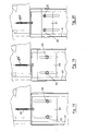
- the framing system comprises a plurality of laterally spaced-apart studs 1 or uprights.
- the studs 1 are interconnected by a header 2 which extends generally horizontally.
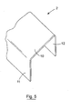
- Each stud 1 comprises an elongated generally C-shaped lipped channel having a web 3 and side flanges 4, 5 which extend continuously the length of the element.
- the side flanges 4, 5 have inturned lips 7, 8 at the upper edge to define a generally C-shaped form.
- Each of the flanges 4, 5 has an elongate slot 6 therein which is typically punched out. The slot 6 is located on the central longitudinal axis of the flanges 4, 5.
- the header 2 is of channel section comprising a web 10 and a pair of flanges 11, 12 which extend to embrace the web 3 and flanges 4, 5 of the studs 1 as illustrated.
- the header 2 is sized such that the depending flanges 11, 12 embrace the studs 1 to which it is to be secured in a relatively tight fit.
- the header 2 is mounted to the studs 1 in such a way as to accommodate limited vertical movement of the header 2 relative to the studs 1.
- Fixings 20 are screwed through the flanges 11, 12 of the header and extend to engage in the slots 6 in the stud flanges 4, 5.
- the fixings 20 preferably have shallow heads in order to eliminate a bulging effect on boarding which is subsequently applied over the stud and track system.
- the overall shaft length will generally be a minimum length of 26mm with coarse thread.
- the minimum design capacity of the fixings is 2.28 kN.
- a number of vertical studs 1 are arranged with their elongate slots 6 at the uppermost ends thereof.
- the studs 1 are spaced-apart in accordance with the specification required.
- a header 2 is then placed over the studs 1 and fasteners or fixings 20 are used to secure the header 2 to the studs 1.
- the fixings 20 are tightened to secure the joint whilst still permitting movement of the header 2 relative to the studs 1 in response to structure settlement during construction.
- the header 2 can move vertically relative to the studs 1. In this way structural parts such as walls carried by the studs 1 are isolated from stresses that may be applied to the header 2, for example from a structure 25 above the header 2 to which the header is attached by fixings 26.
- the header flanges 11, 12 do not have fixing holes therein.
- the fixings 20 may comprise self piercing rivets for connecting the header 2 to the studs 1 through the corresponding fixing regions.
- header flanges 11, 12 may comprise fixing holes for reception of fixings.
- such holes may comprise pilot holes in which case pop rivets may be used as fixings.
- such holes may be sized for use with a staked fixing.
- the fixing hole may comprise a clearance hole for use with a self tapping screw.
- Figs. 11 and 12 there is illustrated another framing system according to the invention which is similar to that described with reference to Figs. 1 to 10 and like parts are assigned the same reference numerals.
- the flanges 11, 12 of the header track 2 have an indicator thereon, in this case in the form of a line 30 which extends along the length of the header 2.
- the marker line 30 indicates to the installer the location to which the fixings 20 should be inserted to guarantee the structure performance because of consistent fixing location.
- the indicator line 30 may be provided on the header flanges 11, 12 in any suitable manner. For example, it can be applied using dedicated marking rollers or may be created using a suitable roll/marking device or printer. The line may be applied before or after roll forming of the track.
- the framing system may be used in any suitable application.
- the system may be used as a wall type frame to which cladding panels may be attached.
- Such as wall may be load bearing or non load bearing and may, for example, form part of a modular building point.
- the screw 20 is fixed in the middle of the stud 1 which improves torsional stability.
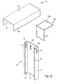
- FIGs. 13 to 20 there is illustrated a framing system according to the invention in which parts similar to those of Figs. 1 to 12 are identified by the same reference numerals.
- the framing system comprising a number of frame elements typically of metal, in this case rolled steel sections.
- the framing system comprises a plurality of laterally spaced-apart studs 41 or uprights.
- the studs 41 are interconnected by a header 2 which extends generally horizontally.
- Each stud 41 comprises an elongated generally C-shaped lipped channel having a web 3 and side flanges 4, 5 which extend continuously the length of the element.
- the side flanges 4, 5 have inturned lips 7, 8 at the upper edge to define a generally C-shaped form.
- Each of the flanges 4, 5 has an elongate slot 6 therein which is typically punched out. The slot 6 is located on the central longitudinal axis of the flanges 4, 5.
- the header 2 is of channel section comprising a web 10 and a pair of flanges 11, 12 which extend to embrace the web 3 and flanges 4, 5 of the studs 41 as illustrated.
- the header 2 is sized such that the depending flanges 11, 12 embrace the studs 41 to which it is to be secured in a relatively tight fit.
- the header 2 is mounted to the studs 41 in such a way as to accommodate limited vertical movement of the header 2 relative to the studs 1.
- Fixings 42 or 43 are screwed through the flanges 11, 12 of the header and extend to engage in the slots 6 in the stud flanges 4, 5.
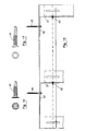
- the web 3 of a stud 41 has a pair of longitudinally extending elongate slots 40 with closed ends.
- the slots 40 are equi-spaced from a central longitudinal axis of the web 3.
- the slots 40 are typically punched out.
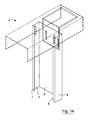
- the system also comprises an ancillary element, such as a structural element, in this case an angle cleat 50 having a stud portion 51 and a track portion 52 which extend in use along the web 3 of the stud 41 and the web 10 of the header track 10 respectively.
- the stud portion 51 of the cleat 50 is attached to the web 3 of the stud 41 by fixings 42 or 43 which extend through the slots 40. Fixing screws 45 may be used to fix the header portion 52 of the cleat through the header 2 to an upper support.
- the fixings 42, 43 preferably have shallow heads in order to eliminate a bulging effect on boarding which is subsequently applied over the stud and track system.
- the overall shaft length will generally be a minimum length of 26mm with coarse thread.
- the minimum design capacity of the fixings is 2.28 kN.
- the system of Figs. 13 to 20 is especially advantageous in that it allows the system to be readily reinforced at the joint between the studs and the header.
- the cleat 50 fixed to the web slots 40 increases the shear capacity of the connection.
- the web slots 40 allow the cleat to be readily fitted and also facilitate any required movement between the cleat to which the header is attached and the stud 41.
- a part (such as a structural beam) of the main structure may render access to one of the slots difficult or impossible.
- the cleat 50 can be fixed/anchored upwards into the head track web 10 and through to a structural substrate using suitable fixings 45. Fixings 42 or 43 may be inserted through the slots 40 in the web 3 of the stud 41 and into the stud portion 51 of the cleat 50.
- the studs 41 can be directly fixed to the face of a slab/structural beam through the slots with no additional cleat or bracket.
- Oversail studs would not require the slots in the oversail cleat which would reduce the cost of this component.
- a number of vertical studs 41 are arranged with their elongate slots 6, 40 at the uppermost ends thereof.
- the studs 41 are spaced-apart in accordance with the specification required.
- a header 2 is then placed over the studs 41 and fasteners or fixings 42,43 are used to secure the header 2 to the studs 41.
- Cleats 50 may be used at some or all of the joints between the studs 41 and header 2.
- the fixings 42, 43 are tightened to secure the joint whilst still permitting movement of the header 2 relative to the studs 41, for example in response to structure settlement during construction.
- the header 2 can move vertically relative to the studs 41. In this way structural parts such as walls carried by the studs 41 are isolated from stresses that may be applied to the header 2, for example from a structure 25 above the header 2 to which the header is attached by fixings 45.
- the header flanges 11, 12 do not have fixing holes therein.
- the fixings 42,43 may comprise self piercing rivets for connecting the header 2 to the studs 1 through the corresponding fixing regions.
- header flanges 11, 12 may comprise fixing holes for reception of fixings.
- such holes may comprise pilot holes in which case pop rivets may be used as fixings.
- such holes may be sized for use with a staked fixing.
- the fixing hole may comprise a clearance hole for use with a self tapping screw.
- the flanges 11, 12 of the header track 2 may have an indicator thereon, such as in the form of a line which extends along the length of the header 2.
- the marker line indicates to the installer the location to which the fixings 20 should be inserted to guarantee the structure performance because of consistent fixing location.
- the indicator line may be provided on the header flanges 11, 12 in any suitable manner. For example, it can be applied using dedicated marking rollers or may be created using a suitable roll/marking device or printer. The line may be applied before or after roll forming of the track.
- the framing system may be used in any suitable application.
- the system may be used as a wall type frame to which cladding panels may be attached.
- Such as wall may be load bearing or non load bearing and may, for example, form part of a modular building point.
- a fixing screw 42, 43 may be fixed in the middle of the stud 41 which improves torsional stability.
- the fixing point is same for all the studs 1 regardless the stud spacing.
- the loading capacity for the connection is consistent.
- the slots 40 are equi-spaced from a central longitudinal axis of the web of the stud 41, the fixing points are same for all the studs 41 regardless the stud spacing.
- the loading capacity for the connection is consistent.
Landscapes
- Engineering & Computer Science (AREA)
- Architecture (AREA)
- Physics & Mathematics (AREA)
- Electromagnetism (AREA)
- Civil Engineering (AREA)
- Structural Engineering (AREA)
- Joining Of Building Structures In Genera (AREA)
Priority Applications (1)
| Application Number | Priority Date | Filing Date | Title |
|---|---|---|---|
| PL10705438T PL2398973T3 (pl) | 2009-02-12 | 2010-02-12 | System szkieletowy |
Applications Claiming Priority (2)
| Application Number | Priority Date | Filing Date | Title |
|---|---|---|---|
| IE20090116 | 2009-02-12 | ||
| PCT/IE2010/000007 WO2010092563A1 (en) | 2009-02-12 | 2010-02-12 | A framing system |
Publications (2)
| Publication Number | Publication Date |
|---|---|
| EP2398973A1 EP2398973A1 (en) | 2011-12-28 |
| EP2398973B1 true EP2398973B1 (en) | 2014-08-20 |
Family
ID=42045228
Family Applications (1)
| Application Number | Title | Priority Date | Filing Date |
|---|---|---|---|
| EP10705438.9A Active EP2398973B1 (en) | 2009-02-12 | 2010-02-12 | A framing system |
Country Status (6)
| Country | Link |
|---|---|
| EP (1) | EP2398973B1 (pl) |
| ES (1) | ES2518442T3 (pl) |
| GB (1) | GB2467843B (pl) |
| IE (1) | IE86383B1 (pl) |
| PL (1) | PL2398973T3 (pl) |
| WO (1) | WO2010092563A1 (pl) |
Families Citing this family (6)
| Publication number | Priority date | Publication date | Assignee | Title |
|---|---|---|---|---|
| EP3239424A1 (de) * | 2016-04-29 | 2017-11-01 | Viessmann Werke GmbH & Co. KG | Rahmenelement, verbindungselement und system mit mindestens einem rahmenelement und einem verbindungselement |
| USD839078S1 (en) | 2018-01-04 | 2019-01-29 | Clarkwestern Dietrich Building Systems Llc | Slide clip |
| US11840835B2 (en) * | 2020-06-01 | 2023-12-12 | Hyperframe, Inc. | Wall stud acoustic performance |
| US11692340B2 (en) | 2020-07-22 | 2023-07-04 | Clarkwestern Dietrich Building Systems Llc | Slide clip |
| USD959250S1 (en) | 2020-07-22 | 2022-08-02 | Clarkwestern Dietrich Building Systems Llc | Slide clip |
| USD959251S1 (en) | 2020-07-22 | 2022-08-02 | Clarkwestern Dietrich Building Systems Llc | Slide clip |
Citations (3)
| Publication number | Priority date | Publication date | Assignee | Title |
|---|---|---|---|---|
| US20030196401A1 (en) * | 2002-04-17 | 2003-10-23 | Matt Surowiecki | Wall construction |
| US20040003564A1 (en) * | 1999-04-16 | 2004-01-08 | Surowiecki Matt F. | Structural walls and construction method |
| US20040083665A1 (en) * | 1999-04-16 | 2004-05-06 | Surowiecki Matt F. | Structural walls |
Family Cites Families (9)
| Publication number | Priority date | Publication date | Assignee | Title |
|---|---|---|---|---|
| US2058386A (en) * | 1932-10-20 | 1936-10-20 | Johns Manville | Wall assembly |
| US3094197A (en) * | 1958-04-30 | 1963-06-18 | Warren R Attwood | Building construction element |
| US3845601A (en) * | 1973-10-17 | 1974-11-05 | Bethlehem Steel Corp | Metal wall framing system |
| AU681217B2 (en) * | 1994-02-09 | 1997-08-21 | Thomas Mccracken Gilmore | Partition wall framing assembly for suspending gypsum board panels |
| US5899035A (en) * | 1997-05-15 | 1999-05-04 | Steelcase, Inc. | Knock-down portable partition system |
| US20030074849A1 (en) * | 2001-10-19 | 2003-04-24 | Matt Surowiecki | Slotted metal stud |
| US20030213207A1 (en) * | 2002-05-16 | 2003-11-20 | Ghislain Belanger | Length adjustable composite stud |
| GB0212734D0 (en) * | 2002-05-31 | 2002-07-10 | Lafarge Plasterboard Ltd | Wall stud |
| US7104024B1 (en) * | 2003-10-20 | 2006-09-12 | The Steel Network, Inc. | Connector for connecting two building members together that permits relative movement between the building members |
-
2010
- 2010-02-12 ES ES10705438.9T patent/ES2518442T3/es active Active
- 2010-02-12 GB GB1002394.3A patent/GB2467843B/en active Active
- 2010-02-12 IE IE20100079A patent/IE86383B1/en not_active IP Right Cessation
- 2010-02-12 PL PL10705438T patent/PL2398973T3/pl unknown
- 2010-02-12 EP EP10705438.9A patent/EP2398973B1/en active Active
- 2010-02-12 WO PCT/IE2010/000007 patent/WO2010092563A1/en not_active Ceased
Patent Citations (3)
| Publication number | Priority date | Publication date | Assignee | Title |
|---|---|---|---|---|
| US20040003564A1 (en) * | 1999-04-16 | 2004-01-08 | Surowiecki Matt F. | Structural walls and construction method |
| US20040083665A1 (en) * | 1999-04-16 | 2004-05-06 | Surowiecki Matt F. | Structural walls |
| US20030196401A1 (en) * | 2002-04-17 | 2003-10-23 | Matt Surowiecki | Wall construction |
Also Published As
| Publication number | Publication date |
|---|---|
| EP2398973A1 (en) | 2011-12-28 |
| IE86383B1 (en) | 2014-04-23 |
| WO2010092563A1 (en) | 2010-08-19 |
| GB2467843A (en) | 2010-08-18 |
| GB201002394D0 (en) | 2010-03-31 |
| ES2518442T3 (es) | 2014-11-05 |
| GB2467843B (en) | 2013-09-04 |
| PL2398973T3 (pl) | 2015-02-27 |
| IE20100079A1 (en) | 2010-09-01 |
Similar Documents
| Publication | Publication Date | Title |
|---|---|---|
| EP2398973B1 (en) | A framing system | |
| US5906080A (en) | Bracket for interconnecting a building stud to primary structural components | |
| US6199336B1 (en) | Metal wall framework and clip | |
| EP2126236B1 (en) | A framing system of studs and rails connected together by adapter members | |
| US6688069B2 (en) | Vertical slide clip | |
| US7765771B2 (en) | Structural framing system and components thereof | |
| US6708460B1 (en) | Stud wall system and method using a combined bridging and spacing device | |
| US11326344B2 (en) | In-frame shear wall | |
| EP3312355A1 (en) | Improved slip clip connection | |
| US20090139176A1 (en) | Slotted Tabbed Rim Track and Building Method | |
| US5836133A (en) | Vertical movement clip for attaching a building member to a beam having a channel therein | |
| CA2917162A1 (en) | Light gauge steel beam-to-column joint with yielding panel zone | |
| US10006219B1 (en) | Frame assembly for seismic retrofitting of soft story buildings | |
| US12320124B2 (en) | Insulated roof systems, support members thereof, and method of installing | |
| KR20190080721A (ko) | 건축용 패널 고정기구 | |
| EP1031669B1 (en) | Building frames with sigma-profile | |
| CA3049483C (en) | Connection system with connector piece for timber constructions | |
| KR20110008010A (ko) | 패널용 연결 요소 | |
| EP3068959B1 (en) | Profile element for supporting at least one wall partition, in particular at least one drywall plasterboard partition and method for producing that profile element | |
| EP2394905B1 (de) | Ein Trägerprofil für eine Bauplatte | |
| KR101895402B1 (ko) | 건축용 패널 고정기구 | |
| JP4684886B2 (ja) | 外壁リフォーム構造およびリフォーム用外壁の施工方法 | |
| US20250101735A1 (en) | Terminal Bridging Connector | |
| EP4067597A2 (en) | Corner support assembly and method for installing same | |
| JP3002693B2 (ja) | システムウォールサッシの取付け構造 |
Legal Events
| Date | Code | Title | Description |
|---|---|---|---|
| PUAI | Public reference made under article 153(3) epc to a published international application that has entered the european phase |
Free format text: ORIGINAL CODE: 0009012 |
|
| 17P | Request for examination filed |
Effective date: 20110909 |
|
| AK | Designated contracting states |
Kind code of ref document: A1 Designated state(s): AT BE BG CH CY CZ DE DK EE ES FI FR GB GR HR HU IE IS IT LI LT LU LV MC MK MT NL NO PL PT RO SE SI SK SM TR |
|
| DAX | Request for extension of the european patent (deleted) | ||
| 17Q | First examination report despatched |
Effective date: 20121210 |
|
| GRAP | Despatch of communication of intention to grant a patent |
Free format text: ORIGINAL CODE: EPIDOSNIGR1 |
|
| INTG | Intention to grant announced |
Effective date: 20140325 |
|
| RBV | Designated contracting states (corrected) |
Designated state(s): AT BE BG CH CY CZ DE DK EE ES FI FR GR HR HU IE IS IT LI LT LU LV MC MK MT NL NO PL PT RO SE SI SK SM TR |
|
| GRAS | Grant fee paid |
Free format text: ORIGINAL CODE: EPIDOSNIGR3 |
|
| GRAA | (expected) grant |
Free format text: ORIGINAL CODE: 0009210 |
|
| AK | Designated contracting states |
Kind code of ref document: B1 Designated state(s): AT BE BG CH CY CZ DE DK EE ES FI FR GR HR HU IE IS IT LI LT LU LV MC MK MT NL NO PL PT RO SE SI SK SM TR |
|
| REG | Reference to a national code |
Ref country code: CH Ref legal event code: EP |
|
| REG | Reference to a national code |
Ref country code: AT Ref legal event code: REF Ref document number: 683563 Country of ref document: AT Kind code of ref document: T Effective date: 20140915 |
|
| REG | Reference to a national code |
Ref country code: IE Ref legal event code: FG4D |
|
| REG | Reference to a national code |
Ref country code: DE Ref legal event code: R096 Ref document number: 602010018365 Country of ref document: DE Effective date: 20141002 |
|
| REG | Reference to a national code |
Ref country code: ES Ref legal event code: FG2A Ref document number: 2518442 Country of ref document: ES Kind code of ref document: T3 Effective date: 20141105 Ref country code: NL Ref legal event code: T3 |
|
| REG | Reference to a national code |
Ref country code: AT Ref legal event code: MK05 Ref document number: 683563 Country of ref document: AT Kind code of ref document: T Effective date: 20140820 |
|
| REG | Reference to a national code |
Ref country code: LT Ref legal event code: MG4D |
|
| PG25 | Lapsed in a contracting state [announced via postgrant information from national office to epo] |
Ref country code: BG Free format text: LAPSE BECAUSE OF FAILURE TO SUBMIT A TRANSLATION OF THE DESCRIPTION OR TO PAY THE FEE WITHIN THE PRESCRIBED TIME-LIMIT Effective date: 20141120 Ref country code: NO Free format text: LAPSE BECAUSE OF FAILURE TO SUBMIT A TRANSLATION OF THE DESCRIPTION OR TO PAY THE FEE WITHIN THE PRESCRIBED TIME-LIMIT Effective date: 20141120 Ref country code: GR Free format text: LAPSE BECAUSE OF FAILURE TO SUBMIT A TRANSLATION OF THE DESCRIPTION OR TO PAY THE FEE WITHIN THE PRESCRIBED TIME-LIMIT Effective date: 20141121 Ref country code: PT Free format text: LAPSE BECAUSE OF FAILURE TO SUBMIT A TRANSLATION OF THE DESCRIPTION OR TO PAY THE FEE WITHIN THE PRESCRIBED TIME-LIMIT Effective date: 20141222 Ref country code: LT Free format text: LAPSE BECAUSE OF FAILURE TO SUBMIT A TRANSLATION OF THE DESCRIPTION OR TO PAY THE FEE WITHIN THE PRESCRIBED TIME-LIMIT Effective date: 20140820 Ref country code: FI Free format text: LAPSE BECAUSE OF FAILURE TO SUBMIT A TRANSLATION OF THE DESCRIPTION OR TO PAY THE FEE WITHIN THE PRESCRIBED TIME-LIMIT Effective date: 20140820 Ref country code: SE Free format text: LAPSE BECAUSE OF FAILURE TO SUBMIT A TRANSLATION OF THE DESCRIPTION OR TO PAY THE FEE WITHIN THE PRESCRIBED TIME-LIMIT Effective date: 20140820 |
|
| PG25 | Lapsed in a contracting state [announced via postgrant information from national office to epo] |
Ref country code: AT Free format text: LAPSE BECAUSE OF FAILURE TO SUBMIT A TRANSLATION OF THE DESCRIPTION OR TO PAY THE FEE WITHIN THE PRESCRIBED TIME-LIMIT Effective date: 20140820 Ref country code: IS Free format text: LAPSE BECAUSE OF FAILURE TO SUBMIT A TRANSLATION OF THE DESCRIPTION OR TO PAY THE FEE WITHIN THE PRESCRIBED TIME-LIMIT Effective date: 20141220 Ref country code: LV Free format text: LAPSE BECAUSE OF FAILURE TO SUBMIT A TRANSLATION OF THE DESCRIPTION OR TO PAY THE FEE WITHIN THE PRESCRIBED TIME-LIMIT Effective date: 20140820 Ref country code: HR Free format text: LAPSE BECAUSE OF FAILURE TO SUBMIT A TRANSLATION OF THE DESCRIPTION OR TO PAY THE FEE WITHIN THE PRESCRIBED TIME-LIMIT Effective date: 20140820 |
|
| REG | Reference to a national code |
Ref country code: PL Ref legal event code: T3 Ref country code: FR Ref legal event code: PLFP Year of fee payment: 6 |
|
| PG25 | Lapsed in a contracting state [announced via postgrant information from national office to epo] |
Ref country code: DK Free format text: LAPSE BECAUSE OF FAILURE TO SUBMIT A TRANSLATION OF THE DESCRIPTION OR TO PAY THE FEE WITHIN THE PRESCRIBED TIME-LIMIT Effective date: 20140820 Ref country code: SK Free format text: LAPSE BECAUSE OF FAILURE TO SUBMIT A TRANSLATION OF THE DESCRIPTION OR TO PAY THE FEE WITHIN THE PRESCRIBED TIME-LIMIT Effective date: 20140820 Ref country code: EE Free format text: LAPSE BECAUSE OF FAILURE TO SUBMIT A TRANSLATION OF THE DESCRIPTION OR TO PAY THE FEE WITHIN THE PRESCRIBED TIME-LIMIT Effective date: 20140820 Ref country code: RO Free format text: LAPSE BECAUSE OF FAILURE TO SUBMIT A TRANSLATION OF THE DESCRIPTION OR TO PAY THE FEE WITHIN THE PRESCRIBED TIME-LIMIT Effective date: 20140820 Ref country code: CZ Free format text: LAPSE BECAUSE OF FAILURE TO SUBMIT A TRANSLATION OF THE DESCRIPTION OR TO PAY THE FEE WITHIN THE PRESCRIBED TIME-LIMIT Effective date: 20140820 Ref country code: IT Free format text: LAPSE BECAUSE OF FAILURE TO SUBMIT A TRANSLATION OF THE DESCRIPTION OR TO PAY THE FEE WITHIN THE PRESCRIBED TIME-LIMIT Effective date: 20140820 |
|
| PGFP | Annual fee paid to national office [announced via postgrant information from national office to epo] |
Ref country code: ES Payment date: 20150326 Year of fee payment: 6 Ref country code: NL Payment date: 20150223 Year of fee payment: 6 |
|
| REG | Reference to a national code |
Ref country code: DE Ref legal event code: R097 Ref document number: 602010018365 Country of ref document: DE |
|
| PGFP | Annual fee paid to national office [announced via postgrant information from national office to epo] |
Ref country code: FR Payment date: 20150227 Year of fee payment: 6 |
|
| PLBE | No opposition filed within time limit |
Free format text: ORIGINAL CODE: 0009261 |
|
| STAA | Information on the status of an ep patent application or granted ep patent |
Free format text: STATUS: NO OPPOSITION FILED WITHIN TIME LIMIT |
|
| PG25 | Lapsed in a contracting state [announced via postgrant information from national office to epo] |
Ref country code: BE Free format text: LAPSE BECAUSE OF NON-PAYMENT OF DUE FEES Effective date: 20150228 |
|
| 26N | No opposition filed |
Effective date: 20150521 |
|
| PGFP | Annual fee paid to national office [announced via postgrant information from national office to epo] |
Ref country code: DE Payment date: 20150429 Year of fee payment: 6 |
|
| PG25 | Lapsed in a contracting state [announced via postgrant information from national office to epo] |
Ref country code: LU Free format text: LAPSE BECAUSE OF FAILURE TO SUBMIT A TRANSLATION OF THE DESCRIPTION OR TO PAY THE FEE WITHIN THE PRESCRIBED TIME-LIMIT Effective date: 20150212 |
|
| REG | Reference to a national code |
Ref country code: CH Ref legal event code: PL |
|
| PG25 | Lapsed in a contracting state [announced via postgrant information from national office to epo] |
Ref country code: MC Free format text: LAPSE BECAUSE OF FAILURE TO SUBMIT A TRANSLATION OF THE DESCRIPTION OR TO PAY THE FEE WITHIN THE PRESCRIBED TIME-LIMIT Effective date: 20140820 Ref country code: CH Free format text: LAPSE BECAUSE OF NON-PAYMENT OF DUE FEES Effective date: 20150228 Ref country code: LI Free format text: LAPSE BECAUSE OF NON-PAYMENT OF DUE FEES Effective date: 20150228 |
|
| REG | Reference to a national code |
Ref country code: IE Ref legal event code: MM4A |
|
| PG25 | Lapsed in a contracting state [announced via postgrant information from national office to epo] |
Ref country code: SI Free format text: LAPSE BECAUSE OF FAILURE TO SUBMIT A TRANSLATION OF THE DESCRIPTION OR TO PAY THE FEE WITHIN THE PRESCRIBED TIME-LIMIT Effective date: 20140820 |
|
| PG25 | Lapsed in a contracting state [announced via postgrant information from national office to epo] |
Ref country code: IE Free format text: LAPSE BECAUSE OF NON-PAYMENT OF DUE FEES Effective date: 20150212 |
|
| PG25 | Lapsed in a contracting state [announced via postgrant information from national office to epo] |
Ref country code: BE Free format text: LAPSE BECAUSE OF FAILURE TO SUBMIT A TRANSLATION OF THE DESCRIPTION OR TO PAY THE FEE WITHIN THE PRESCRIBED TIME-LIMIT Effective date: 20140820 |
|
| REG | Reference to a national code |
Ref country code: DE Ref legal event code: R119 Ref document number: 602010018365 Country of ref document: DE |
|
| REG | Reference to a national code |
Ref country code: NL Ref legal event code: MM Effective date: 20160301 |
|
| REG | Reference to a national code |
Ref country code: FR Ref legal event code: ST Effective date: 20161028 |
|
| PG25 | Lapsed in a contracting state [announced via postgrant information from national office to epo] |
Ref country code: MT Free format text: LAPSE BECAUSE OF FAILURE TO SUBMIT A TRANSLATION OF THE DESCRIPTION OR TO PAY THE FEE WITHIN THE PRESCRIBED TIME-LIMIT Effective date: 20140820 |
|
| PG25 | Lapsed in a contracting state [announced via postgrant information from national office to epo] |
Ref country code: FR Free format text: LAPSE BECAUSE OF NON-PAYMENT OF DUE FEES Effective date: 20160229 Ref country code: DE Free format text: LAPSE BECAUSE OF NON-PAYMENT OF DUE FEES Effective date: 20160901 Ref country code: NL Free format text: LAPSE BECAUSE OF NON-PAYMENT OF DUE FEES Effective date: 20160301 |
|
| PG25 | Lapsed in a contracting state [announced via postgrant information from national office to epo] |
Ref country code: SM Free format text: LAPSE BECAUSE OF FAILURE TO SUBMIT A TRANSLATION OF THE DESCRIPTION OR TO PAY THE FEE WITHIN THE PRESCRIBED TIME-LIMIT Effective date: 20140820 Ref country code: HU Free format text: LAPSE BECAUSE OF FAILURE TO SUBMIT A TRANSLATION OF THE DESCRIPTION OR TO PAY THE FEE WITHIN THE PRESCRIBED TIME-LIMIT; INVALID AB INITIO Effective date: 20100212 Ref country code: ES Free format text: LAPSE BECAUSE OF NON-PAYMENT OF DUE FEES Effective date: 20160213 |
|
| PG25 | Lapsed in a contracting state [announced via postgrant information from national office to epo] |
Ref country code: CY Free format text: LAPSE BECAUSE OF FAILURE TO SUBMIT A TRANSLATION OF THE DESCRIPTION OR TO PAY THE FEE WITHIN THE PRESCRIBED TIME-LIMIT Effective date: 20140820 |
|
| PG25 | Lapsed in a contracting state [announced via postgrant information from national office to epo] |
Ref country code: TR Free format text: LAPSE BECAUSE OF FAILURE TO SUBMIT A TRANSLATION OF THE DESCRIPTION OR TO PAY THE FEE WITHIN THE PRESCRIBED TIME-LIMIT Effective date: 20140820 |
|
| PG25 | Lapsed in a contracting state [announced via postgrant information from national office to epo] |
Ref country code: MK Free format text: LAPSE BECAUSE OF FAILURE TO SUBMIT A TRANSLATION OF THE DESCRIPTION OR TO PAY THE FEE WITHIN THE PRESCRIBED TIME-LIMIT Effective date: 20140820 |
|
| PGFP | Annual fee paid to national office [announced via postgrant information from national office to epo] |
Ref country code: PL Payment date: 20250120 Year of fee payment: 16 |