EP2398094A1 - Lithium cell - Google Patents
Lithium cell Download PDFInfo
- Publication number
- EP2398094A1 EP2398094A1 EP11181043A EP11181043A EP2398094A1 EP 2398094 A1 EP2398094 A1 EP 2398094A1 EP 11181043 A EP11181043 A EP 11181043A EP 11181043 A EP11181043 A EP 11181043A EP 2398094 A1 EP2398094 A1 EP 2398094A1
- Authority
- EP
- European Patent Office
- Prior art keywords
- cell
- cathode
- anode
- fes
- theoretical capacity
- Prior art date
- Legal status (The legal status is an assumption and is not a legal conclusion. Google has not performed a legal analysis and makes no representation as to the accuracy of the status listed.)
- Withdrawn
Links
- 229910052744 lithium Inorganic materials 0.000 title claims abstract description 80
- WHXSMMKQMYFTQS-UHFFFAOYSA-N Lithium Chemical compound [Li] WHXSMMKQMYFTQS-UHFFFAOYSA-N 0.000 title claims abstract description 56
- NIFIFKQPDTWWGU-UHFFFAOYSA-N pyrite Chemical compound [Fe+2].[S-][S-] NIFIFKQPDTWWGU-UHFFFAOYSA-N 0.000 claims abstract description 120
- OKTJSMMVPCPJKN-UHFFFAOYSA-N Carbon Chemical compound [C] OKTJSMMVPCPJKN-UHFFFAOYSA-N 0.000 claims abstract description 20
- NFMAZVUSKIJEIH-UHFFFAOYSA-N bis(sulfanylidene)iron Chemical compound S=[Fe]=S NFMAZVUSKIJEIH-UHFFFAOYSA-N 0.000 claims abstract description 19
- 229910000339 iron disulfide Inorganic materials 0.000 claims abstract description 19
- 239000002245 particle Substances 0.000 claims abstract description 14
- 229910052799 carbon Inorganic materials 0.000 claims abstract description 12
- 229910052683 pyrite Inorganic materials 0.000 claims abstract description 8
- ZCYVEMRRCGMTRW-UHFFFAOYSA-N 7553-56-2 Chemical compound [I] ZCYVEMRRCGMTRW-UHFFFAOYSA-N 0.000 claims abstract description 3
- 239000011630 iodine Substances 0.000 claims abstract description 3
- 229910052740 iodine Inorganic materials 0.000 claims abstract description 3
- 229910052960 marcasite Inorganic materials 0.000 claims abstract 5
- 239000000758 substrate Substances 0.000 claims description 64
- 239000000203 mixture Substances 0.000 claims description 25
- 238000000576 coating method Methods 0.000 claims description 23
- 239000011248 coating agent Substances 0.000 claims description 21
- 239000006182 cathode active material Substances 0.000 claims description 16
- -1 polyethylene Polymers 0.000 claims description 15
- 239000006183 anode active material Substances 0.000 claims description 14
- 229910000733 Li alloy Inorganic materials 0.000 claims description 11
- 239000001989 lithium alloy Substances 0.000 claims description 9
- 239000004698 Polyethylene Substances 0.000 claims description 5
- 239000004743 Polypropylene Substances 0.000 claims description 5
- 239000011255 nonaqueous electrolyte Substances 0.000 claims description 5
- 229920000573 polyethylene Polymers 0.000 claims description 5
- 229920001155 polypropylene Polymers 0.000 claims description 5
- 239000012229 microporous material Substances 0.000 claims 1
- 239000003792 electrolyte Substances 0.000 abstract description 35
- NUJOXMJBOLGQSY-UHFFFAOYSA-N manganese dioxide Chemical compound O=[Mn]=O NUJOXMJBOLGQSY-UHFFFAOYSA-N 0.000 description 27
- 239000002904 solvent Substances 0.000 description 23
- 239000006257 cathode slurry Substances 0.000 description 22
- 239000002131 composite material Substances 0.000 description 21
- 229910003002 lithium salt Inorganic materials 0.000 description 16
- 159000000002 lithium salts Chemical class 0.000 description 16
- XEEYBQQBJWHFJM-UHFFFAOYSA-N Iron Chemical compound [Fe] XEEYBQQBJWHFJM-UHFFFAOYSA-N 0.000 description 13
- 229910052782 aluminium Inorganic materials 0.000 description 13
- XAGFODPZIPBFFR-UHFFFAOYSA-N aluminium Chemical compound [Al] XAGFODPZIPBFFR-UHFFFAOYSA-N 0.000 description 13
- 238000012360 testing method Methods 0.000 description 13
- XTHFKEDIFFGKHM-UHFFFAOYSA-N Dimethoxyethane Chemical compound COCCOC XTHFKEDIFFGKHM-UHFFFAOYSA-N 0.000 description 12
- 239000000463 material Substances 0.000 description 12
- 239000011888 foil Substances 0.000 description 10
- 229910052751 metal Inorganic materials 0.000 description 10
- 239000002184 metal Substances 0.000 description 10
- PXHVJJICTQNCMI-UHFFFAOYSA-N Nickel Chemical compound [Ni] PXHVJJICTQNCMI-UHFFFAOYSA-N 0.000 description 8
- POIUWJQBRNEFGX-XAMSXPGMSA-N cathelicidin Chemical compound C([C@@H](C(=O)N[C@@H](CCCNC(N)=N)C(=O)N[C@@H](CCCCN)C(=O)N[C@@H](CO)C(=O)N[C@@H](CCCCN)C(=O)N[C@@H](CCC(O)=O)C(=O)N[C@@H](CCCCN)C(=O)N[C@@H]([C@@H](C)CC)C(=O)NCC(=O)N[C@@H](CCCCN)C(=O)N[C@@H](CCC(O)=O)C(=O)N[C@@H](CC=1C=CC=CC=1)C(=O)N[C@@H](CCCCN)C(=O)N[C@@H](CCCNC(N)=N)C(=O)N[C@@H]([C@@H](C)CC)C(=O)N[C@@H](C(C)C)C(=O)N[C@@H](CCC(N)=O)C(=O)N[C@@H](CCCNC(N)=N)C(=O)N[C@@H]([C@@H](C)CC)C(=O)N[C@@H](CCCCN)C(=O)N[C@@H](CC(O)=O)C(=O)N[C@@H](CC=1C=CC=CC=1)C(=O)N[C@@H](CC(C)C)C(=O)N[C@@H](CCCNC(N)=N)C(=O)N[C@@H](CC(N)=O)C(=O)N[C@@H](CC(C)C)C(=O)N[C@@H](C(C)C)C(=O)N1[C@@H](CCC1)C(=O)N[C@@H](CCCNC(N)=N)C(=O)N[C@@H]([C@@H](C)O)C(=O)N[C@@H](CCC(O)=O)C(=O)N[C@@H](CO)C(O)=O)NC(=O)[C@H](CC=1C=CC=CC=1)NC(=O)[C@H](CC(O)=O)NC(=O)CNC(=O)[C@H](CC(C)C)NC(=O)[C@@H](N)CC(C)C)C1=CC=CC=C1 POIUWJQBRNEFGX-XAMSXPGMSA-N 0.000 description 8
- 239000003960 organic solvent Substances 0.000 description 8
- 239000002002 slurry Substances 0.000 description 8
- 239000007787 solid Substances 0.000 description 8
- 230000002829 reductive effect Effects 0.000 description 7
- 229920002633 Kraton (polymer) Polymers 0.000 description 6
- WYURNTSHIVDZCO-UHFFFAOYSA-N Tetrahydrofuran Chemical compound C1CCOC1 WYURNTSHIVDZCO-UHFFFAOYSA-N 0.000 description 6
- 239000011230 binding agent Substances 0.000 description 6
- 239000000843 powder Substances 0.000 description 6
- WNXJIVFYUVYPPR-UHFFFAOYSA-N 1,3-dioxolane Chemical compound C1COCO1 WNXJIVFYUVYPPR-UHFFFAOYSA-N 0.000 description 5
- KMTRUDSVKNLOMY-UHFFFAOYSA-N Ethylene carbonate Chemical compound O=C1OCCO1 KMTRUDSVKNLOMY-UHFFFAOYSA-N 0.000 description 5
- 229910001560 Li(CF3SO2)2N Inorganic materials 0.000 description 5
- 239000010405 anode material Substances 0.000 description 5
- 239000010406 cathode material Substances 0.000 description 5
- 229910001416 lithium ion Inorganic materials 0.000 description 5
- MCVFFRWZNYZUIJ-UHFFFAOYSA-M lithium;trifluoromethanesulfonate Chemical compound [Li+].[O-]S(=O)(=O)C(F)(F)F MCVFFRWZNYZUIJ-UHFFFAOYSA-M 0.000 description 5
- RUOJZAUFBMNUDX-UHFFFAOYSA-N propylene carbonate Chemical compound CC1COC(=O)O1 RUOJZAUFBMNUDX-UHFFFAOYSA-N 0.000 description 5
- 150000003839 salts Chemical class 0.000 description 5
- 239000011877 solvent mixture Substances 0.000 description 5
- 230000008901 benefit Effects 0.000 description 4
- 229910002804 graphite Inorganic materials 0.000 description 4
- 239000010439 graphite Substances 0.000 description 4
- AMXOYNBUYSYVKV-UHFFFAOYSA-M lithium bromide Chemical compound [Li+].[Br-] AMXOYNBUYSYVKV-UHFFFAOYSA-M 0.000 description 4
- HSZCZNFXUDYRKD-UHFFFAOYSA-M lithium iodide Chemical compound [Li+].[I-] HSZCZNFXUDYRKD-UHFFFAOYSA-M 0.000 description 4
- 229910052759 nickel Inorganic materials 0.000 description 4
- 238000006722 reduction reaction Methods 0.000 description 4
- 239000010935 stainless steel Substances 0.000 description 4
- 229910001220 stainless steel Inorganic materials 0.000 description 4
- HXJUTPCZVOIRIF-UHFFFAOYSA-N sulfolane Chemical compound O=S1(=O)CCCC1 HXJUTPCZVOIRIF-UHFFFAOYSA-N 0.000 description 4
- 238000004804 winding Methods 0.000 description 4
- WEVYAHXRMPXWCK-UHFFFAOYSA-N Acetonitrile Chemical compound CC#N WEVYAHXRMPXWCK-UHFFFAOYSA-N 0.000 description 3
- 239000006230 acetylene black Substances 0.000 description 3
- 239000006229 carbon black Substances 0.000 description 3
- 238000013461 design Methods 0.000 description 3
- 238000003487 electrochemical reaction Methods 0.000 description 3
- 239000007772 electrode material Substances 0.000 description 3
- 229910052742 iron Inorganic materials 0.000 description 3
- 238000000034 method Methods 0.000 description 3
- 230000002093 peripheral effect Effects 0.000 description 3
- 239000000047 product Substances 0.000 description 3
- 239000011028 pyrite Substances 0.000 description 3
- 230000027756 respiratory electron transport chain Effects 0.000 description 3
- YLQBMQCUIZJEEH-UHFFFAOYSA-N tetrahydrofuran Natural products C=1C=COC=1 YLQBMQCUIZJEEH-UHFFFAOYSA-N 0.000 description 3
- 238000003466 welding Methods 0.000 description 3
- ZZXUZKXVROWEIF-UHFFFAOYSA-N 1,2-butylene carbonate Chemical compound CCC1COC(=O)O1 ZZXUZKXVROWEIF-UHFFFAOYSA-N 0.000 description 2
- AKUSZFPCJFNRSZ-UHFFFAOYSA-N 3,4-dimethyl-1,2-oxazole Chemical compound CC1=CON=C1C AKUSZFPCJFNRSZ-UHFFFAOYSA-N 0.000 description 2
- FICAQKBMCKEFDI-UHFFFAOYSA-N 3,5-dimethyl-1,2-oxazole Chemical compound CC=1C=C(C)ON=1 FICAQKBMCKEFDI-UHFFFAOYSA-N 0.000 description 2
- YEJRWHAVMIAJKC-UHFFFAOYSA-N 4-Butyrolactone Chemical compound O=C1CCCO1 YEJRWHAVMIAJKC-UHFFFAOYSA-N 0.000 description 2
- OYPRJOBELJOOCE-UHFFFAOYSA-N Calcium Chemical compound [Ca] OYPRJOBELJOOCE-UHFFFAOYSA-N 0.000 description 2
- OIFBSDVPJOWBCH-UHFFFAOYSA-N Diethyl carbonate Chemical compound CCOC(=O)OCC OIFBSDVPJOWBCH-UHFFFAOYSA-N 0.000 description 2
- 229910001216 Li2S Inorganic materials 0.000 description 2
- HBBGRARXTFLTSG-UHFFFAOYSA-N Lithium ion Chemical compound [Li+] HBBGRARXTFLTSG-UHFFFAOYSA-N 0.000 description 2
- XBDQKXXYIPTUBI-UHFFFAOYSA-M Propionate Chemical compound CCC([O-])=O XBDQKXXYIPTUBI-UHFFFAOYSA-M 0.000 description 2
- 229910000831 Steel Inorganic materials 0.000 description 2
- KXKVLQRXCPHEJC-UHFFFAOYSA-N acetic acid trimethyl ester Natural products COC(C)=O KXKVLQRXCPHEJC-UHFFFAOYSA-N 0.000 description 2
- 239000011149 active material Substances 0.000 description 2
- 125000002015 acyclic group Chemical group 0.000 description 2
- 229910045601 alloy Inorganic materials 0.000 description 2
- 239000000956 alloy Substances 0.000 description 2
- 229910002065 alloy metal Inorganic materials 0.000 description 2
- 229910052791 calcium Inorganic materials 0.000 description 2
- 239000011575 calcium Substances 0.000 description 2
- 238000003490 calendering Methods 0.000 description 2
- 238000006243 chemical reaction Methods 0.000 description 2
- 239000007795 chemical reaction product Substances 0.000 description 2
- 230000001010 compromised effect Effects 0.000 description 2
- 125000004122 cyclic group Chemical group 0.000 description 2
- VAYGXNSJCAHWJZ-UHFFFAOYSA-N dimethyl sulfate Chemical compound COS(=O)(=O)OC VAYGXNSJCAHWJZ-UHFFFAOYSA-N 0.000 description 2
- 238000007599 discharging Methods 0.000 description 2
- 238000001035 drying Methods 0.000 description 2
- 239000004210 ether based solvent Substances 0.000 description 2
- 239000007789 gas Substances 0.000 description 2
- 150000003949 imides Chemical class 0.000 description 2
- 230000006872 improvement Effects 0.000 description 2
- 229910001496 lithium tetrafluoroborate Inorganic materials 0.000 description 2
- 239000012528 membrane Substances 0.000 description 2
- 239000003791 organic solvent mixture Substances 0.000 description 2
- 230000036961 partial effect Effects 0.000 description 2
- 229920000642 polymer Polymers 0.000 description 2
- 229920005996 polystyrene-poly(ethylene-butylene)-polystyrene Polymers 0.000 description 2
- 230000008569 process Effects 0.000 description 2
- 230000009467 reduction Effects 0.000 description 2
- 239000000523 sample Substances 0.000 description 2
- 239000010959 steel Substances 0.000 description 2
- 239000000126 substance Substances 0.000 description 2
- LZDKZFUFMNSQCJ-UHFFFAOYSA-N 1,2-diethoxyethane Chemical compound CCOCCOCC LZDKZFUFMNSQCJ-UHFFFAOYSA-N 0.000 description 1
- RYHBNJHYFVUHQT-UHFFFAOYSA-N 1,4-Dioxane Chemical compound C1COCCO1 RYHBNJHYFVUHQT-UHFFFAOYSA-N 0.000 description 1
- FZKPQHFEMFIDNR-UHFFFAOYSA-N 2-hydroxyethyl hydrogen sulfite Chemical compound OCCOS(O)=O FZKPQHFEMFIDNR-UHFFFAOYSA-N 0.000 description 1
- JWUJQDFVADABEY-UHFFFAOYSA-N 2-methyltetrahydrofuran Chemical compound CC1CCCO1 JWUJQDFVADABEY-UHFFFAOYSA-N 0.000 description 1
- VWIIJDNADIEEDB-UHFFFAOYSA-N 3-methyl-1,3-oxazolidin-2-one Chemical compound CN1CCOC1=O VWIIJDNADIEEDB-UHFFFAOYSA-N 0.000 description 1
- 229910000838 Al alloy Inorganic materials 0.000 description 1
- 239000004215 Carbon black (E152) Substances 0.000 description 1
- RYGMFSIKBFXOCR-UHFFFAOYSA-N Copper Chemical compound [Cu] RYGMFSIKBFXOCR-UHFFFAOYSA-N 0.000 description 1
- 229910007042 Li(CF3SO2)3 Inorganic materials 0.000 description 1
- 229910001290 LiPF6 Inorganic materials 0.000 description 1
- NINIDFKCEFEMDL-UHFFFAOYSA-N Sulfur Chemical compound [S] NINIDFKCEFEMDL-UHFFFAOYSA-N 0.000 description 1
- 239000000654 additive Substances 0.000 description 1
- 239000000853 adhesive Substances 0.000 description 1
- 230000001070 adhesive effect Effects 0.000 description 1
- 230000009286 beneficial effect Effects 0.000 description 1
- 229920001400 block copolymer Polymers 0.000 description 1
- 229930188620 butyrolactone Natural products 0.000 description 1
- 229910052802 copper Inorganic materials 0.000 description 1
- 239000010949 copper Substances 0.000 description 1
- 238000005336 cracking Methods 0.000 description 1
- 230000003247 decreasing effect Effects 0.000 description 1
- 238000011161 development Methods 0.000 description 1
- SBZXBUIDTXKZTM-UHFFFAOYSA-N diglyme Chemical compound COCCOCCOC SBZXBUIDTXKZTM-UHFFFAOYSA-N 0.000 description 1
- IEJIGPNLZYLLBP-UHFFFAOYSA-N dimethyl carbonate Chemical compound COC(=O)OC IEJIGPNLZYLLBP-UHFFFAOYSA-N 0.000 description 1
- VUPKGFBOKBGHFZ-UHFFFAOYSA-N dipropyl carbonate Chemical compound CCCOC(=O)OCCC VUPKGFBOKBGHFZ-UHFFFAOYSA-N 0.000 description 1
- 230000000694 effects Effects 0.000 description 1
- 229920001971 elastomer Polymers 0.000 description 1
- 239000000806 elastomer Substances 0.000 description 1
- 239000012777 electrically insulating material Substances 0.000 description 1
- 239000011262 electrochemically active material Substances 0.000 description 1
- 230000005518 electrochemistry Effects 0.000 description 1
- 239000002001 electrolyte material Substances 0.000 description 1
- 239000008151 electrolyte solution Substances 0.000 description 1
- 230000001747 exhibiting effect Effects 0.000 description 1
- 238000009472 formulation Methods 0.000 description 1
- 239000008240 homogeneous mixture Substances 0.000 description 1
- 229930195733 hydrocarbon Natural products 0.000 description 1
- 150000002430 hydrocarbons Chemical class 0.000 description 1
- 239000011261 inert gas Substances 0.000 description 1
- 239000012212 insulator Substances 0.000 description 1
- 238000010030 laminating Methods 0.000 description 1
- 230000000670 limiting effect Effects 0.000 description 1
- 229910001540 lithium hexafluoroarsenate(V) Inorganic materials 0.000 description 1
- 238000004519 manufacturing process Methods 0.000 description 1
- 230000007246 mechanism Effects 0.000 description 1
- 229910052987 metal hydride Inorganic materials 0.000 description 1
- 239000012046 mixed solvent Substances 0.000 description 1
- 238000002156 mixing Methods 0.000 description 1
- 239000005486 organic electrolyte Substances 0.000 description 1
- 238000013021 overheating Methods 0.000 description 1
- 230000003647 oxidation Effects 0.000 description 1
- 238000007254 oxidation reaction Methods 0.000 description 1
- 239000002985 plastic film Substances 0.000 description 1
- 229920006255 plastic film Polymers 0.000 description 1
- 229920000728 polyester Polymers 0.000 description 1
- 239000011148 porous material Substances 0.000 description 1
- 230000002035 prolonged effect Effects 0.000 description 1
- 230000001737 promoting effect Effects 0.000 description 1
- 238000004080 punching Methods 0.000 description 1
- 239000000243 solution Substances 0.000 description 1
- 239000007858 starting material Substances 0.000 description 1
- 229910052717 sulfur Inorganic materials 0.000 description 1
- 239000011593 sulfur Substances 0.000 description 1
- YFNKIDBQEZZDLK-UHFFFAOYSA-N triglyme Chemical compound COCCOCCOCCOC YFNKIDBQEZZDLK-UHFFFAOYSA-N 0.000 description 1
- XLYOFNOQVPJJNP-UHFFFAOYSA-N water Substances O XLYOFNOQVPJJNP-UHFFFAOYSA-N 0.000 description 1
Images


Classifications
-
- H—ELECTRICITY
- H01—ELECTRIC ELEMENTS
- H01M—PROCESSES OR MEANS, e.g. BATTERIES, FOR THE DIRECT CONVERSION OF CHEMICAL ENERGY INTO ELECTRICAL ENERGY
- H01M4/00—Electrodes
- H01M4/02—Electrodes composed of, or comprising, active material
- H01M4/36—Selection of substances as active materials, active masses, active liquids
- H01M4/58—Selection of substances as active materials, active masses, active liquids of inorganic compounds other than oxides or hydroxides, e.g. sulfides, selenides, tellurides, halogenides or LiCoFy; of polyanionic structures, e.g. phosphates, silicates or borates
-
- H—ELECTRICITY
- H01—ELECTRIC ELEMENTS
- H01M—PROCESSES OR MEANS, e.g. BATTERIES, FOR THE DIRECT CONVERSION OF CHEMICAL ENERGY INTO ELECTRICAL ENERGY
- H01M4/00—Electrodes
- H01M4/02—Electrodes composed of, or comprising, active material
- H01M4/06—Electrodes for primary cells
-
- H—ELECTRICITY
- H01—ELECTRIC ELEMENTS
- H01M—PROCESSES OR MEANS, e.g. BATTERIES, FOR THE DIRECT CONVERSION OF CHEMICAL ENERGY INTO ELECTRICAL ENERGY
- H01M4/00—Electrodes
- H01M4/02—Electrodes composed of, or comprising, active material
- H01M4/06—Electrodes for primary cells
- H01M4/08—Processes of manufacture
- H01M4/12—Processes of manufacture of consumable metal or alloy electrodes
-
- H—ELECTRICITY
- H01—ELECTRIC ELEMENTS
- H01M—PROCESSES OR MEANS, e.g. BATTERIES, FOR THE DIRECT CONVERSION OF CHEMICAL ENERGY INTO ELECTRICAL ENERGY
- H01M4/00—Electrodes
- H01M4/02—Electrodes composed of, or comprising, active material
- H01M4/36—Selection of substances as active materials, active masses, active liquids
- H01M4/38—Selection of substances as active materials, active masses, active liquids of elements or alloys
- H01M4/381—Alkaline or alkaline earth metals elements
- H01M4/382—Lithium
-
- H—ELECTRICITY
- H01—ELECTRIC ELEMENTS
- H01M—PROCESSES OR MEANS, e.g. BATTERIES, FOR THE DIRECT CONVERSION OF CHEMICAL ENERGY INTO ELECTRICAL ENERGY
- H01M4/00—Electrodes
- H01M4/02—Electrodes composed of, or comprising, active material
- H01M4/36—Selection of substances as active materials, active masses, active liquids
- H01M4/38—Selection of substances as active materials, active masses, active liquids of elements or alloys
- H01M4/40—Alloys based on alkali metals
-
- H—ELECTRICITY
- H01—ELECTRIC ELEMENTS
- H01M—PROCESSES OR MEANS, e.g. BATTERIES, FOR THE DIRECT CONVERSION OF CHEMICAL ENERGY INTO ELECTRICAL ENERGY
- H01M4/00—Electrodes
- H01M4/02—Electrodes composed of, or comprising, active material
- H01M4/36—Selection of substances as active materials, active masses, active liquids
- H01M4/58—Selection of substances as active materials, active masses, active liquids of inorganic compounds other than oxides or hydroxides, e.g. sulfides, selenides, tellurides, halogenides or LiCoFy; of polyanionic structures, e.g. phosphates, silicates or borates
- H01M4/581—Chalcogenides or intercalation compounds thereof
- H01M4/5815—Sulfides
-
- H—ELECTRICITY
- H01—ELECTRIC ELEMENTS
- H01M—PROCESSES OR MEANS, e.g. BATTERIES, FOR THE DIRECT CONVERSION OF CHEMICAL ENERGY INTO ELECTRICAL ENERGY
- H01M50/00—Constructional details or processes of manufacture of the non-active parts of electrochemical cells other than fuel cells, e.g. hybrid cells
- H01M50/40—Separators; Membranes; Diaphragms; Spacing elements inside cells
- H01M50/409—Separators, membranes or diaphragms characterised by the material
- H01M50/411—Organic material
- H01M50/414—Synthetic resins, e.g. thermoplastics or thermosetting resins
- H01M50/417—Polyolefins
-
- H—ELECTRICITY
- H01—ELECTRIC ELEMENTS
- H01M—PROCESSES OR MEANS, e.g. BATTERIES, FOR THE DIRECT CONVERSION OF CHEMICAL ENERGY INTO ELECTRICAL ENERGY
- H01M50/00—Constructional details or processes of manufacture of the non-active parts of electrochemical cells other than fuel cells, e.g. hybrid cells
- H01M50/40—Separators; Membranes; Diaphragms; Spacing elements inside cells
- H01M50/489—Separators, membranes, diaphragms or spacing elements inside the cells, characterised by their physical properties, e.g. swelling degree, hydrophilicity or shut down properties
- H01M50/491—Porosity
-
- H—ELECTRICITY
- H01—ELECTRIC ELEMENTS
- H01M—PROCESSES OR MEANS, e.g. BATTERIES, FOR THE DIRECT CONVERSION OF CHEMICAL ENERGY INTO ELECTRICAL ENERGY
- H01M6/00—Primary cells; Manufacture thereof
- H01M6/14—Cells with non-aqueous electrolyte
- H01M6/16—Cells with non-aqueous electrolyte with organic electrolyte
- H01M6/162—Cells with non-aqueous electrolyte with organic electrolyte characterised by the electrolyte
- H01M6/168—Cells with non-aqueous electrolyte with organic electrolyte characterised by the electrolyte by additives
-
- H—ELECTRICITY
- H01—ELECTRIC ELEMENTS
- H01M—PROCESSES OR MEANS, e.g. BATTERIES, FOR THE DIRECT CONVERSION OF CHEMICAL ENERGY INTO ELECTRICAL ENERGY
- H01M6/00—Primary cells; Manufacture thereof
- H01M6/50—Methods or arrangements for servicing or maintenance, e.g. for maintaining operating temperature
-
- H—ELECTRICITY
- H01—ELECTRIC ELEMENTS
- H01M—PROCESSES OR MEANS, e.g. BATTERIES, FOR THE DIRECT CONVERSION OF CHEMICAL ENERGY INTO ELECTRICAL ENERGY
- H01M4/00—Electrodes
- H01M4/02—Electrodes composed of, or comprising, active material
- H01M2004/021—Physical characteristics, e.g. porosity, surface area
-
- H—ELECTRICITY
- H01—ELECTRIC ELEMENTS
- H01M—PROCESSES OR MEANS, e.g. BATTERIES, FOR THE DIRECT CONVERSION OF CHEMICAL ENERGY INTO ELECTRICAL ENERGY
- H01M6/00—Primary cells; Manufacture thereof
- H01M6/50—Methods or arrangements for servicing or maintenance, e.g. for maintaining operating temperature
- H01M2006/5094—Aspects relating to capacity ratio of electrolyte/electrodes or anode/cathode
-
- H—ELECTRICITY
- H01—ELECTRIC ELEMENTS
- H01M—PROCESSES OR MEANS, e.g. BATTERIES, FOR THE DIRECT CONVERSION OF CHEMICAL ENERGY INTO ELECTRICAL ENERGY
- H01M2300/00—Electrolytes
- H01M2300/0017—Non-aqueous electrolytes
- H01M2300/0025—Organic electrolyte
- H01M2300/0028—Organic electrolyte characterised by the solvent
- H01M2300/0037—Mixture of solvents
-
- H—ELECTRICITY
- H01—ELECTRIC ELEMENTS
- H01M—PROCESSES OR MEANS, e.g. BATTERIES, FOR THE DIRECT CONVERSION OF CHEMICAL ENERGY INTO ELECTRICAL ENERGY
- H01M4/00—Electrodes
- H01M4/02—Electrodes composed of, or comprising, active material
- H01M4/04—Processes of manufacture in general
- H01M4/043—Processes of manufacture in general involving compressing or compaction
- H01M4/0435—Rolling or calendering
-
- H—ELECTRICITY
- H01—ELECTRIC ELEMENTS
- H01M—PROCESSES OR MEANS, e.g. BATTERIES, FOR THE DIRECT CONVERSION OF CHEMICAL ENERGY INTO ELECTRICAL ENERGY
- H01M50/00—Constructional details or processes of manufacture of the non-active parts of electrochemical cells other than fuel cells, e.g. hybrid cells
- H01M50/10—Primary casings; Jackets or wrappings
- H01M50/102—Primary casings; Jackets or wrappings characterised by their shape or physical structure
- H01M50/107—Primary casings; Jackets or wrappings characterised by their shape or physical structure having curved cross-section, e.g. round or elliptic
-
- H—ELECTRICITY
- H01—ELECTRIC ELEMENTS
- H01M—PROCESSES OR MEANS, e.g. BATTERIES, FOR THE DIRECT CONVERSION OF CHEMICAL ENERGY INTO ELECTRICAL ENERGY
- H01M6/00—Primary cells; Manufacture thereof
- H01M6/04—Cells with aqueous electrolyte
- H01M6/06—Dry cells, i.e. cells wherein the electrolyte is rendered non-fluid
- H01M6/10—Dry cells, i.e. cells wherein the electrolyte is rendered non-fluid with wound or folded electrodes
-
- H—ELECTRICITY
- H01—ELECTRIC ELEMENTS
- H01M—PROCESSES OR MEANS, e.g. BATTERIES, FOR THE DIRECT CONVERSION OF CHEMICAL ENERGY INTO ELECTRICAL ENERGY
- H01M6/00—Primary cells; Manufacture thereof
- H01M6/14—Cells with non-aqueous electrolyte
- H01M6/16—Cells with non-aqueous electrolyte with organic electrolyte
- H01M6/162—Cells with non-aqueous electrolyte with organic electrolyte characterised by the electrolyte
- H01M6/166—Cells with non-aqueous electrolyte with organic electrolyte characterised by the electrolyte by the solute
-
- Y—GENERAL TAGGING OF NEW TECHNOLOGICAL DEVELOPMENTS; GENERAL TAGGING OF CROSS-SECTIONAL TECHNOLOGIES SPANNING OVER SEVERAL SECTIONS OF THE IPC; TECHNICAL SUBJECTS COVERED BY FORMER USPC CROSS-REFERENCE ART COLLECTIONS [XRACs] AND DIGESTS
- Y02—TECHNOLOGIES OR APPLICATIONS FOR MITIGATION OR ADAPTATION AGAINST CLIMATE CHANGE
- Y02E—REDUCTION OF GREENHOUSE GAS [GHG] EMISSIONS, RELATED TO ENERGY GENERATION, TRANSMISSION OR DISTRIBUTION
- Y02E60/00—Enabling technologies; Technologies with a potential or indirect contribution to GHG emissions mitigation
- Y02E60/10—Energy storage using batteries
Definitions
- the invention relates to lithium primary cells having an anode comprising lithium and a cathode comprising iron disulfide, wherein the ratio of the theoretical capacity of the anode to theoretical capacity of the cathode is greater than 1.0.
- Primary (non-rechargeable) electrochemical cells having an anode of lithium are known and are in widespread commercial use.
- the anode is comprised essentially of lithium metal.
- Such cells typically have a cathode comprising manganese dioxide, and electrolyte comprising a lithium salt such as lithium trifluoromethane sulfonate (LiCF 3 SO 3 ) dissolved in a nonaqueous solvent.
- the cells are referenced in the art as primary lithium cells and are generally not intended to be rechargeable.
- a common primary lithium cell has a lithium anode and cathode comprising MnO 2 (Li/MnO 2 cell) used to power 35 mm cameras.
- Alternative primary lithium cells with lithium metal anodes but having different cathodes are also known.
- Such cells for example, have cathodes comprising iron disulfide (FeS 2 ) and are designated Li/FeS 2 cells.
- the iron disulfide (FeS 2 ) is also known as
- the Li/MnO 2 cells or Li/FeS 2 cells are typically in the form of cylindrical cells, typically an AA or AAA size cell or 2/3A size cell having wound electrodes with separator sheet therebetween.
- the Li/MnO 2 cells have a voltage of about 3.0 volts which is twice that of conventional Zn/MnO 2 alkaline cells and also have higher energy density (watt-hrs per cm 3 of cell volume) than that of alkaline cells.
- the Li/FeS 2 cells have a voltage (fresh) of between about 1.2 and 1.8 volts which is about the same as a conventional Zn/MnO 2 alkaline cell.
- the energy density (watt-hrs per cm 3 of cell volume) of the Li/FeS 2 cell is much higher than a comparable size Zn/MnO 2 alkaline cell.
- the theoretical specific capacity of lithium metal is high at 3861.4 mAmp-hr/gram and the theoretical specific capacity of FeS 2 is 893.6 mAmp-hr/gram.
- the FeS 2 theoretical capacity is based on a 4 electron transfer from 4Li per FeS 2 molecule to result in reaction product of elemental iron Fe and 2Li 2 S. That is, 2 of the 4 electrons reduce the valence state of Fe +2 in FeS 2 to Fe and the remaining 2 electrons reduce the valence of sulfur from -1 in FeS 2 to -2 in Li 2 S.
- the lithium ions, Li + produced at the anode must transport through the separator and electrolyte medium and to the cathode.
- Li/FeS 2 cell is much more powerful than the same size Zn/MnO 2 alkaline cell. That is, for a given continuous current drain, particularly for higher current drain over 200 milliAmp, as reflected by the voltage vs. time discharge profile the voltage drops off much less quickly for the Li/FeS 2 cell than the Zn/MnO 2 alkaline cell. This results in a higher energy output obtainable from a Li/FeS 2 cell compared to that obtainable for a same size alkaline cell.
- the higher energy output of the Li/FeS 2 cell is also clearly shown more directly in graphical plots of energy (Watt-hrs) versus continuous discharge at constant power (Watts) wherein fresh cells are discharged to completion at fixed continuous power outputs ranging from as little as 0.01 Watt to 5 Watt. In such tests the power drain is maintained at a constant continuous power output selected between 0.01 Watt and 5 Watt. (As the cell's voltage drops during discharge the load resistance is gradually decreased raising the current drain to maintain a fixed constant power output.)
- the graphical plot Energy (Watt-Hrs) versus Power Output (Watt) for the Li/FeS 2 cell is considerably above that for the same size alkaline cell. This is despite that the starting voltage of both cells (OCV) is about the same, namely, between about 1.2 and 1.8 volt.
- the Li/FeS 2 cell has the advantage over same size alkaline cell, for example, AAAA, AAA, AA, C or D size or any other size in that the Li/FeS 2 may be used interchangeably with the conventional Zn/MnO 2 alkaline cell and will have greater service life, particularly for higher power demands.
- the Li/FeS 2 cell which is primary (nonrechargeable) can be used as a replacement for the same size rechargeable nickel metal hydride cell, which has about the same voltage (fresh) as the Li/FeS 2 cell.
- the electrochemical cell's anode and cathode may be balanced so that the theoretical capacity (mAmp-hr) of either the anode or cathode is in excess.
- Zn/MnO 2 alkaline cells are typically balanced so that the theoretical capacity of the cathode is greater than the theoretical capacity of the anode. See, e.g. U.S 6,585,881 B2 wherein it is stated that the ratio of theoretical capacity of the cathode to the theoretical capacity of the anode is about 1.05 at col. 15, lines 33-36.
- a better definition of the term theoretical capacity of the anode involves computing the ideal capacity (mAmp-hrs) of all the anode active materials therein, and the theoretical capacity of the cathode involves computing the ideal capacity (mAmp-hrs) of all the cathode active materials therein. It shall be understood that the use of such terms theoretical capacity of anode and theoretical capacity of cathode as used in the present application shall be so defined.
- the "anode active" materials and "cathode active” materials are defined as the materials in the anode and cathode, respectively, which are capable of useful electrochemical discharge. That is, the “anode active materials” and “cathode active materials” promote current flow between the cell's negative and positive terminals when an external circuit between these terminals is connected and the cell is used in normal manner.
- the Li/FeS 2 cell requires and electrolyte formed of a lithium salt dissolved in organic electrolyte solvent, since the lithium anode is highly reactive with water.
- One of the difficulties associated with the manufacture of a Li/FeS 2 cell is the need to add good binding material to the cathode formulation to bind the Li/FeS 2 and carbon particles together in the cathode.
- the binding material must also be sufficiently adhesive to cause the cathode coating to adhere uniformly and strongly to the substrate to which the cathode coating is applied and yet must resist chemical attack by the electrolyte.
- the cathode material may be initially prepared in the form of a slurry mixture, which can be readily coated onto the substrate, preferably a metal substrate by conventional coating methods.
- the electrolyte added to the cell must be a suitable electrolyte for the Li/FeS 2 system allowing the necessary electrochemical reactions to occur efficiently over the range of high power output desired.
- the electrolyte must exhibit good ionic conductivity and also be sufficiently stable, that is, non reactive, with the undischarged electrode materials (anode and cathode components) and also non reactive with the discharge products.
- the electrolyte used in Li/FeS 2 cell in addition to promoting the necessary electrochemical reactions, should also be stable to discharged and undischarged electrode materials. Additionally, the electrolyte should enable good ionic mobility and transport of the lithium ion (Li + ) from anode to cathode so that it can engage in the necessary reduction reaction resulting in Li 2 S product in the cathode.
- Primary lithium cells are in use as a power source for digital flash cameras, which require operation at higher pulsed power demands than is supplied by individual alkaline cells.
- Primary lithium cells are conventionally formed of an electrode composite comprising an anode formed of a sheet of lithium or lithium alloy, a cathode formed of a coating of cathode active material comprising MnO 2 or FeS 2 on a conductive metal substrate (cathode substrate) and a sheet of electrolyte permeable separator material therebetween.
- the electrode composite may be spirally wound and inserted into the cell casing, for examples, as shown in U.S. patent 4,707,421 .
- a cathode coating mixture for the Li/FeS 2 cell is described in U.S. 6,849,360 .
- a portion of the anode sheet is typically electrically connected to the cell casing which forms the cell's negative terminal.
- the cell is closed with an end cap which is insulated from the casing.
- the cathode sheet can be electrically connected to the end cap which forms the cell's positive terminal.
- the casing is typically crimped over the peripheral edge of the end cap with insulator disk therebetween to seal the casing's open end.
- the cell may be fitted internally with a PTC (positive thermal coefficient) device or the like to shut down (increase the internal resistance) of the cell in case the cell is exposed to abusive conditions such as short circuit discharge or overheating.
- the anode in a Li/FeS 2 cell can be formed by laminating a layer of lithium on a metallic substrate such as copper.
- the anode may be formed of a sheet of lithium or lithium alloy without any substrate.
- the electrolyte used in primary Li/FeS 2 cells is formed of a "lithium salt" dissolved in an "organic solvent".
- Representative lithium salts which may be used in electrolytes for Li/FeS 2 primary cells are referenced in U.S. patents 5,290,414 and U.S.
- Lithium trifluoromethanesulfonate LiCF 3 SO 3 (LiTFS); lithium bistrifluoromethylsulfonyl imide, Li(CF 3 SO 2 ) 2 N (LiTFSI); lithium iodide, LiI; lithium bromide, LiBr; lithium tetrafluoroborate, LiBF 4 ; lithium hexafluorophosphate, LiPF 6 ; lithium hexafluoroarsenate, LiAsF 6 ; Li(CF 3 SO 2 ) 3 C, and various mixtures.
- lithium salts are not simply interchangeable as specific salts are workable with specific electrolyte solvent mixtures.
- a beneficial electrolyte for FeS 2 cells wherein the electrolyte comprises a lithium salt dissolved in a solvent comprising 1,3-dioxolane in admixture with a second solvent which is an acyclic (non cyclic) ether based solvent.
- the acyclic (non cyclic) ether based solvent as referenced may be dimethoxyethane (DME), ethyl glyme, diglyme and triglyme, with the preferred being 1,2-dimetoxyethane (DME).
- the 1,2-dimethoxyethane (DME) is present in the electrolyte in substantial amount, i.e., at either 40 or 75 vol.% (col. 7, lines 47-54).
- a specific lithium salt ionizable in such solvent mixture(s), as given in the example, is lithium trifluoromethane sulfonate, LiCF 3 SO 3 .
- a third solvent may optionally be added selected from 3,5-dimethlyisoxazole (DMI), 3-methyl-2-oxazolidone, propylene carbonate (PC), ethylene carbonate (EC), butylene carbonate (BC), tetrahydrofuran (THF), diethyl carbonate (DEC), ethylene glycol sulfite (EGS), dioxane, dimethyl sulfate (DMS), and sulfolane (claim 19) with the preferred being 3,5-dimethylisoxazole.
- DMI 3,5-dimethlyisoxazole
- PC propylene carbonate
- EC ethylene carbonate
- BC butylene carbonate
- THF tetrahydrofuran
- DEC diethyl carbonate
- EGS ethylene glycol sulfite
- dioxane dimethyl sulfate
- DMS dimethyl sulfate
- sulfolane claim 19
- Non rechargeable Li/MnO 2 or Li/FeS 2 cells or rechargeable lithium or lithium ion cells reveals that just any combination of lithium salt and organic solvent cannot be expected to result in a good cell, that is, exhibiting good, reliable performance.
- references which merely provide long lists of possible organic solvents for Li/FeS 2 cells do not necessarily teach combinations of solvents or combination of specific lithium salts in specific solvent mixtures, which exhibit particular or unexpected benefit.
- the invention is directed to lithium primary cells wherein the anode comprises lithium metal.
- the lithium may be alloyed with small amounts of other metal, for example aluminum, which typically comprises less than about 1 or 2 wt.% of the lithium alloy.
- the lithium which forms the anode active material is preferably in the form of a thin foil.
- the cell has a cathode comprising the cathode active material iron disulfide (FeS 2 ), commonly known as "pyrite”.
- FeS 2 iron disulfide
- the cell may be in the form of a button (coin) cell or flat cell. Desirably the cell may be in the form of a spirally wound cell comprising an anode sheet and a cathode composite sheet spirally wound with separator therebetween.
- the cathode sheet is produced using a slurry process to coat a cathode mixture comprising iron disulfide (FeS 2 ) and carbon particles onto a substrate, preferably a conductive metal substrate.
- FeS 2 and carbon particles are bound to the substrate using desirably an elastomeric, preferably, a styrene-ethylene /butylene-styrene (SEBS) block copolymer such as Kraton G1651 elastomer (Kraton Polymers, Houston, Texas).
- SEBS styrene-ethylene /butylene-styrene
- This polymer is a film-former, and possesses good affinity and cohesive properties for the FeS 2 particles as well as for conductive carbon particle additives in the cathode mixture. The polymer resists chemical attack by the electrolyte.
- the cathode is formed of a cathode slurry comprising iron disulfide (FeS 2 ) powder, conductive carbon particles, binder material, and solvent.
- FeS 2 iron disulfide
- conductive carbon particles conductive carbon particles
- binder material binder material
- solvent solvent
- the wet cathode slurry is coated onto a substrate which is preferably conductive such as a sheet of aluminum or stainless steel.
- the substrate functions as a cathode current collector.
- the solvent is then evaporated leaving dry cathode coating mixture comprising the iron disulfide material and carbon particles preferably including carbon black adhesively bound to each other and with the dry coating bound to the substrate.
- the preferred carbon black is acetylene black.
- the carbon may optionally include graphite particles blended therein.
- the coated substrate is placed in an oven and heated at elevated temperatures until the solvent evaporates, as disclosed in commonly assigned U.S. patent application 11/516534, filed Sept. 6, 2006 .
- the resulting product is a dry cathode coating comprising iron disulfide and carbon particles bound to the conductive substrate.
- the cathode preferably contains no more than 4% by weight binder, and between 85 and 95% by weight of FeS 2 .
- the solids content, that is, the FeS 2 particles and conductive carbon particles in the wet cathode slurry is typically between 55 and 70 percent by weight.
- the risk of discontinuities developing on the surface of lithium anode of a Li/FeS 2 cell is reduced by balancing the cell so that the theoretical capacity (mAmp-hrs) of the anode is greater than the theoretical capacity (mAmp-hrs) of the cathode. This reduces the chance that the lithium anode will develop discontinuities in its surface or will become severed from electrical contact with the anode current collector as the lithium anode becomes thinner during cell discharge.
- the Li/FeS 2 cell is desirably balanced so that the anode to cathode theoretical capacity ratio is greater than 1.0, regardless of cell size.
- the cell is balanced so that the anode is in theoretical capacity excess as compared to the theoretical capacity of the cathode.
- the Li/FeS 2 cell is balanced so that the anode to cathode theoretical capacity ratio is between about 1.02 and 1.20, desirably between about 1.05 and 1.15, regardless of cell size.
- the Li/FeS 2 cell size may be AA or AAA cylindrical size or smaller or larger sizes. It shall be understood that the theoretical capacity of the anode and theoretical capacity of the cathode is based on those portions of anode and cathode with separator therebetween so that said anode and cathode portions are dischargeable.
- the above indicated Li/FeS 2 cell balance is made in conjunction with increasing the interfacial surface area for a given size wound cell, for example, AA or AAA size cylindrical cells.
- the interfacial area is the largest facing surface area between anode and cathode with separator therebetween, so that said anode and cathode are dischargeable.
- Area designations (cm 2 ) as recited herein shall be understood to apply to the interfacial area between anode and cathode unless otherwise indicated.
- the interfacial area between anode and cathode is increased to a level greater than about 250 cm 2 , preferably between about 250 and 400 cm 2 , desirably at about 300 cm 2 .
- the interfacial surface area between anode and cathode of commercial AA size Li/FeS 2 wound cells are presently at about 220 cm 2 .
- By increasing the interfacial surface area between anode and cathode the ratio of theoretical cathode capacity (mAmp-hrs) to interfacial surface area (cm 2 ) is reduced. This also reduces the current density (mAmp/cm 2 ) for any given current drain rate.
- the ratio of theoretical cathode capacity to interfacial area for Li/FeS 2 wound cells, in particular AA size cells is between about 11 and 15 mAmp-hrs/cm 2 . If each side of the substrate is coated with cathode material then the preceding ratios between 11 and 15 mAmp-hrs/cm 2 are applied to each side. (Commercial AA size Li/FeS 2 wound cells presently have ratio of theoretical cathode capacity to interfacial area of about 17 per side of substrate.)
- the cathode is preferably coated on each side of a substrate so that there is sufficient loading of cathode active material in the cathode resulting in ratio of theoretical cathode capacity to interfacial area of between about 9 and 17 mAmp-hrs/cm 2 per side of the substrate, preferably between about 11 and 15 mAmp-hrs/cm 2 per side of the substrate.
- the anode/cathode interfacial area is desirably greater than about 100 cm 2 , preferably between about 150 and 200 cm 2 .
- the separator is desirably of microporous polyethylene or microporous polypropylene which is somewhat thinner than conventionally employed in lithium cells.
- the separator as applied to the Li/FeS 2 wound cells herein have a thickness between about 0.008 and 0.025, for example, about 0.016 mm.
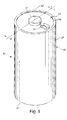
- the Li/FeS 2 cell of the invention is desirably in the form of a spirally wound cell as shown in Figs. 1-5 .
- a desirable wound cell 10 configuration comprising a lithium anode 40 and a cathode composite 62 comprising iron disulfide (FeS 2 ) with separator sheet 50 therebetween is shown in the figures.
- the anode may comprise a sheet of lithium or lithium alloy 40.
- the cathode composite may comprise a coating of cathode material 60 comprising iron disulfide (FeS 2 ) which is coated on at least one side of a substrate 65 as shown best in Figs. 4 and 5 .
- the cathode material 60 may also be coated on both sides of substrate 65.
- the cathode coating 60 is first coated as a wet cathode slurry onto at least one side of substrate 65 and then dried.
- the wet cathode slurry is coated on one side of substrate 65, dried.
- the same wet cathode slurry composition is then also coated on the opposite side of substrate 65 and subsequently dried, thus forming dry cathode coating 60 on both sides of substrate 65.
- the substrate or grid 65 is preferably an electrically conductive substrate, such as a sheet of aluminum, or stainless steel foil.
- the substrate 65 may be a continuous solid sheet without apertures or may be a sheet with apertures therein, for example, formed from expanded stainless steel foil or expanded aluminum foil.
- the anode 40 can be prepared from a solid sheet of lithium metal.
- the anode 40 is desirably formed of a continuous sheet of lithium metal (99.8 % pure).
- the anode 40 can be an alloy of lithium and an alloy metal, for example, an alloy of lithium and aluminum or lithium and calcium. In such case the alloy metal, is present in very small quantity, preferably less than 1 or 2 percent by weight of the lithium alloy. Upon cell discharge the lithium in the alloy thus functions electrochemically as pure lithium.
- the term "lithium or lithium metal” as used herein and in the claims is intended to include in its meaning such lithium alloy.
- the lithium sheet forming anode 40 does not require a substrate.
- the lithium anode 40 can be advantageously formed from an extruded sheet of lithium metal having a thickness of desirably between about 0.10 and 0.20 mm desirably between about 0.12 and 0.19 mm.
- the Li/FeS 2 wound cell is designed to have a balance of anode to cathode so that the anode active material is in excess.
- anode active material or “cathode active material” as used herein means the material in the anode or cathode, respectively, which engages in useful electrochemical discharge.
- the cell 10, representative of a wound Li/FeS 2 cylindrical cell configuration is balanced so that the theoretical capacity (mAmp-hrs) of the anode is greater than the theoretical capacity of the cathode.
- the ratio of the theoretical capacity of the anode to the theoretical capacity of the cathode is greater than 1.0, desirably between about 1.02 and 1.20, for example, between about 1.05 and 1.15.
- the theoretical capacity of the anode is the sum of the theoretical capacity (mAmp-hrs) of all the anode active materials in the anode.
- the theoretical capacity of the cathode is the sum of the theoretical capacity (mAmp-hrs) of all the cathode active materials in the cathode. It will be understood that the theoretical capacity of anode and cathode applies to only that portion of the anode and cathode layers which are facing each other with separator therebetween so that the active materials therein are capable of discharging.
- the theoretical capacity (mAmp-hrs) of the anode and theoretical capacity (mAmp-hrs) of the cathode, respectively are based on all the “anode active materials” and all the “cathode active materials”, respectively, usefully discharging. That is, it is based on 100 percent utilization of the anode active materials and 100 percent utilization of the cathode active materials, respectively, according to the normal discharge reactions occurring in the cell with respect to those active materials.
- the above indicated Li/FeS 2 cell balance (theoretical capacity (mAmp-hrs) of the anode greater than the theoretical capacity (mAmp-hrs) of the cathode) is preferably made in conjunction with increasing the interfacial surface area for a given size wound cell, for example, AA or AAA size cells.
- a AA size cell the interfacial surface area between anode and cathode is increased to a level greater than about 250 cm 2 , preferably between about 250 and 400 cm 2 , desirably at about 300 cm 2 .
- the interfacial area is the facing area between the anode and cathode with separator therebetween.
- the ratio of theoretical cathode capacity (mAmp-hrs) to interfacial surface area (cm 2 ) is reduced. This also reduces the current density (mAmp/cm 2 interfacial area) for any given current drain rate (mAmp).
- the reduction in ratio of theoretical cathode capacity to interfacial area improves the discharge utilization of the cathode as it generally results in thinner cathodes.
- utilization as used herein is the percent of theoretical capacity which is actually attained during cell discharge.
- the increase in interfacial surface area is desirably such that the cell's total capacity is not compromised, despite the thinner cathodes. The improvement in cathode utilization is more apparent at high rate discharge needed to power digital cameras.
- the ratio of theoretical cathode capacity to interfacial area for Li/FeS 2 wound cells, in particular AA size cells is between about 9 and 17 mAmp-hrs/cm 2 preferably between about 11 and 15 mAmp-hrs/cm 2 . If each side of the substrate 65 is coated with cathode material 60 then the preceding ratios of between 11 and 15 mAmp-hrs/cm 2 are applied to each side.
- the Li/FeS 2 cell as in cell 10 has the following basic discharge reactions (one step mechanism):
- the Li/FeS 2 cylindrical cell 10 may be in the form of a primary (nonrechargeable) cell.
- the theoretical specific capacity (mAmp-hr/g) of FeS 2 can be calculated as follows based on a 4 electron transfer per molecule, wherein 2 electrons reduce Fe +2 to elemental iron Fe and 2 electrons reduce S -1 to 2S -2 forming Fe + 2Li 2 S.
- the molecular weight (M.W.) of FeS 2 is 119.97 and the M.W. of Li is 6.941.
- the charge q o of an electron is 1.602 x 10 -19 coulomb/electron.
- 1 coul 1 Amp-sec.
- Avogadro's number A 0 is 6.023 x 10 23 molecules per mol.
- a preferred cathode slurry mixture is presented in Table 1: Table I Cathode Composition Wet Slurry (wt.%) Binder (Kraton G1651) 2.0 Hydorcarbon Solvent (Shellsol A100) 13.4 (ShellSol OMS) 20.2 FeS 2 Powder (Pyrox Red 325) 58.9 Graphite (Timrex KS6) 4.0 Acetylene Carbon Black(Super P) 1.5 Total 100.0
- the Li/FeS 2 cell may be in the configuration of a cylindrical cell 10 as shown in Fig. 1 .
- the cylindrical cell 10 may have a spirally wound anode sheet 40, cathode 60 with separator sheet 50 therebetween as shown in Figs. 2-5 .
- the Li/FeS 2 cell 10 internal configuration, apart from the difference in cathode composition, may be similar to the spirally wound configuration shown and described in U.S. patent 6,443,999 .
- the anode sheet 40 as shown in the figures comprises lithium metal and the cathode sheet 60 comprises iron disulfide (FeS 2 ) commonly known as "pyrite".
- the cell is preferably cylindrical as shown in the figures and may be of any size, for example, AAAA (42 x 8 mm), AAA (44 x 10 mm), AA (50 x 14 mm), C (49 x 25.5 mm) and D (60 x 33 mm) size.
- cell 10 depicted in Fig. 1 may also be a 2/3 A cell (35 x 15 mm). However, it is not intended to limit the cell configuration to cylindrical shape.
- the cell of the invention may have an anode comprising lithium metal and a cathode comprising iron disulfide (FeS 2 ) having the composition and nonaqueous electrolyte as herein described in the form of a spirally wound prismatic cell, for example a rectangular cell having the overall shape of a cuboid.
- the Li/FeS 2 cell is not limited to a spirally wound configuration but the anode and cathode, for example, may be placed in stacked arrangement for use in coin cells.
- a preferred shape of the cell casing (housing) 20 is cylindrical as shown in Fig. 1 .
- Casing 20 is preferably formed of nickel plated steel.
- the cell casing 20 ( Fig. 1 ) has a continuous cylindrical surface.
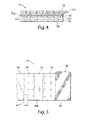
- the spiral wound electrode assembly 70 ( Fig. 3 ) comprising anode 40 and cathode composite 62 with separator 50 therebetween can be prepared by spirally winding a flat electrode composite 13 ( Figs. 4 and 5 ).
- Cathode composite 62 comprises a layer of cathode 60 comprising iron disulfide (FeS 2 ) coated onto metallic substrate 65 ( Fig. 4 ).
- the electrode composite 13 ( Figs. 4 and 5 ) can be made in the following manner:
- the cathode 60 comprising iron disulfide (FeS 2 ) powder dispersed therein can be initially prepared in the form of a wet slurry which is coated onto a side of conductive substrate sheet 65, preferably a sheet of aluminum or stainless steel which may a solid sheet with or without apertures therethrough, to form a cathode composite sheet 62 ( Fig. 4 ).
- Conventional roll coating techniques may be used to coat the wet slurry onto a side of conductive substrate 65 ( Figs. 4 and 5 ).
- an aluminum sheet 65 may be a solid sheet of aluminum without openings therethrough or may be a sheet of expanded or perforated aluminum foil with openings therethrough thus forming a grid or screen.
- the apertures in substrate sheet 65 may be the result of punching or piercing holes therein.
- the wet cathode slurry mixture having the composition shown above in Table 1 comprising iron disulfide (FeS 2 ), binder, conductive carbon and solvents is prepared by mixing the components shown in Table 1 until a homogeneous mixture is obtained.
- the above quantities of components can be scaled proportionally so that small or large batches of cathode slurry can be prepared.
- the wet cathode slurry thus preferably has the following composition: FeS 2 powder (58.9 wt.%); Binder, Kraton G1651 (2 wt.%); Graphite, Timrex KS6 (4.0 wt%), Acetylene Black, Super P (1.5 wt%), Hydrocarbon Solvents, ShellSol A100 (13.4 wt%) and ShellSol OMS (20.2 wt%).
- the wet slurry is then coated onto a side of the conductive substrate 65.
- the conductive substrate 65 with wet cathode slurry coated thereon is then dried in conventional convective oven (or in inert gas) to evaporate the solvents in the slurry, thereby forming a dry cathode coating 60 on one side of conductive substrate 65 ( Figs. 4 and 5 ).
- the process is repeated, if desired, to also coat the opposite side of conductive substrate 65 with the wet cathode slurry (Table 1).
- the wet cathode slurry on the opposite side of conductive substrate 65 can then be subjected to drying in a convective oven to evaporate solvents, thereby forming a dry cathode coating 60 also on the opposite side of conductive substrate 65.
- the drying of the wet cathode slurry coated on the metal substrate 65 is accomplished preferably by gradually adjusting or ramping up the oven temperature (to avoid cracking the coating) from an initial temperature of 40° C to a final temperature not to exceed 130° C for about 7-8 minutes or until the solvent has substantially all evaporated.
- the dry cathode coating 60 (whether applied to only one side or both sides of conductive substrate 65) is then subjected to calendering to compress the thickness of said dry cathode 60, thus forming the completed cathode composite 62 ( Figs. 4 and 5 ).
- the anode 40 can be prepared from a solid sheet of lithium metal.
- the anode 40 is desirably formed of a continuous sheet of lithium metal (99.8 % pure).
- the lithium metal in anode 40 may be alloyed with small amounts of other metal, for example aluminum, or calcium which typically comprises less than about 1 or 2 wt.%, and even up to about 5 wt.% of the lithium alloy.
- the lithium which forms the anode active material is preferably in the form of a thin foil. Upon cell discharge the lithium in the alloy thus functions electrochemically as pure lithium.
- the term "lithium or lithium metal" as used herein and in the claims is intended to include in its meaning such lithium alloy.
- the lithium sheet forming anode 40 does not require a substrate.
- the lithium anode 40 can be advantageously formed from an extruded sheet of lithium metal having a thickness of between about 0.09 and 0.20 mm desirably between about 0.09 and 0.19 mm for the spirally wound cell.
- Individual sheets of electrolyte permeable separator material 50 preferably of microporous polypropylene or polyethylene having a thickness of about 0.025 mm or less is inserted on each side of the lithium anode sheet 40 ( Figs. 4 and 5 ).
- the separator sheet may be microporous polyethylene or polypropylene of thickness about 0.016 mm.
- the microporous polypropylene desirably has a pore size between about 0.001 and 5 micron.
- the first (top) separator sheet 50 ( Fig. 4 ) can be designated the outer separator sheet and the second sheet 50 ( Fig. 4 ) can be designated the inner separator sheet.
- the cathode composite sheet 62 comprising cathode coating 60 on conductive substrate 65 is then placed against the inner separator sheet 50 to form the flat electrode composite 13 shown in Fig. 4 .
- the flat composite 13 ( Fig. 4 ) is spirally wound to form electrode spiral assembly 70 ( Fig. 3 ).
- the winding can be accomplished using a mandrel to grip an extended separator edge 50b ( Fig. 4 ) of electrode composite 13 and then spirally winding composite 13 clockwise to form wound electrode assembly 70 ( Fig.3 ).
- separator portion 50b appears within the core 98 of the wound electrode assembly 70 as shown in Figs. 2 and 3 .
- the bottom edges 50a of each revolution of the separator may be heat formed into a continuous membrane 55 as shown in Fig. 3 and taught in U.S. patent 6,443,999 .
- the electrode spiral 70 has separator material 50 between anode sheet 40 and cathode composite 62.
- the spirally wound electrode assembly 70 has a configuration ( Fig. 3 ) conforming to the shape of the casing body.
- the spirally wound electrode assembly 70 is inserted into the open end 30 of casing 20.
- the outer layer of the electrode spiral 70 comprises separator material 50 shown in Figs.
- An additional insulating layer 72 for example, a plastic film such as polyester tape, can desirably be placed over a of the outer separator layer 50, before the electrode composite 13 is wound.
- the spirally wound electrode 70 will have insulating layer 72 in contact with the inside surface of casing 20 ( Figs. 2 and 3 ) when the wound electrode composite is inserted into the casing.
- the inside surface of the casing 20 can be coated with electrically insulating material 72 before the wound electrode spiral 70 is inserted into the casing.
- a nonaqueous electrolyte mixture can then be added to the wound electrode spiral 70 after it is inserted into the cell casing 20.
- the desired nonaqueous electrolyte comprises a lithium salt LiCF 3 SO 3 (LiTFS) or Li(CF 3 SO 2 ) 2 N (LiTFSI) dissolved in an organic nonaqueous solvent.
- LiTFS lithium salt LiCF 3 SO 3
- LiTFSI Li(CF 3 SO 2 ) 2 N
- Such electrolyte may comprise a solution comprising 0.8 molar (0.8 mol/liter) concentration of LiTFSI salt dissolved in an organic solvent mixture comprising about 75 vol.% methyl acetate (MA), 20 vol.% propylene carbonate (PC), and 5 vol.% ethylene carbonate (EC). Elemental iodine in the amount comprising about 0.5 wt% of the electrolyte is desirably added to the electrolyte, as in commonly assigned U.S. patent application Ser. 11/516,534 . The electrolyte mixture is desirably added on the basis of about 0.4 gram electrolyte solution per gram FeS 2 for the spirally wound cell ( Fig. 2 ).
- Another desirable electrolyte is comprised of a mixture of Li(CF 3 SO 2 ) 2 N (LiTFSI) salt dissolved in a solvent mixture of 1,3 dioxolane (75 vol%) and sulfolane (25 vol %), as in commonly assigned U.S. patent application Ser. 11/494,244 .
- An end cap 18 forming the cell's positive terminal 17 may have a metal tab 25 (cathode tab) which can be welded on one of its sides to inside surface of end cap 18.
- Metal tab 25 is preferably of aluminum or aluminum alloy.
- a portion of the cathode substrate 65 may be flared along its top edge forming an extended portion 64 extending from the top of the wound spiral as shown in figure 2 .
- the flared cathode substrate portion 64 can be welded to the exposed side of metal tab 25 before the casing peripheral edge 22 is crimped around the end cap 18 with peripheral edge 85 of insulating disk 80 therebetween to close the cell's open end 30.
- End cap 18 desirably has a vent 19 which can contain a rupturable membrane designed to rupture and allow gas to escape if the gas pressure within the cell exceeds a predetermined level.
- Positive terminal 17 is desirably an integral portion of end cap 18.
- terminal 17 can be formed as the top of an end cap assembly of the type described in U.S. patent 5,879,832 , which assembly can be inserted into an opening in the surface of end cap 18 and then welded thereto.
- a metal tab 44 (anode tab), preferably of nickel, or nickel plated steel, can be pressed into a portion of the lithium metal anode 40.
- Anode tab 44 can be pressed into the lithium metal at any point within the spiral, for example, it can be pressed into the lithium metal at the outermost layer of the spiral as shown in Fig. 5 .
- Anode tab 44 can be embossed on one side forming a plurality of raised portions on the side of the tab to be pressed into the lithium.
- the opposite side of tab 44 can be welded to the inside surface of the casing either to the inside surface of the casing side wall 24 or more preferably to the inside surface of closed end 35 of casing 20 as shown in Fig. 3 .
- anode tab 44 it is preferable to weld anode tab 44 to the inside surface of the casing closed end 35, since this is readily accomplished by inserting an electrical spot welding probe (an elongated resistance welding electrode) into the cell core 98. Care should be taken to avoid contacting the welding probe to the separator starter tab 50b which is present along a portion of the outer boundary of cell core 98.
- an electrical spot welding probe an elongated resistance welding electrode
- the primary lithium cell 10 may optionally also be provided with a PTC (positive thermal coefficient) device 95 located under the end cap 18 and connected in series between the cathode 60 and end cap 18 ( Fig. 2 ).
- PTC positive thermal coefficient
- Such device protects the cell from discharge at a current drain higher than a predetermined level.
- an abnormally high current e.g., higher than about 6 to 8 Amp in a AA size cell for a prolonged period
- the resistance of the PTC device increases dramatically, thus shutting down the abnormally high drain.
- devices other than vent 19 and PTC device 95 may be employed to protect the cell from abusive use or discharge.
- the cathode capacity utilization in a Li/FeS 2 cell, such as representative wound cell 10, the cathode capacity utilization, particularly at high rate discharge, can be improved if the cathode is designed so that the ratio of cathode theoretical capacity (mAmp-hrs) to electrode interfacial area is reduced.
- the electrode interfacial area is the facing area between the anode 40 and cathode 60 with separator sheet 50 therebetween.
- the cathode utilization is the cathode efficiency as measured by the actual cathode capacity (mAmp-hrs) divided by the theoretical cathode capacity.
- the cathode in effect can be made thinner. This improves cathode utilization and increases cell voltage, particularly at high rate discharge conditions, for example, simulating use of the cell in powering digital cameras.
- a benefit of the improved Li/FeS 2 cell design resulting in higher cathode utilization and higher load voltage is that it becomes possible to employ lithium metal in the anode in amount so that the ratio of anode theoretical capacity (mAmp-hrs) to cathode theoretical capacity is greater than 1.0.
- the cell for example, an AA or AAA size cell, is designed so that the ratio of cathode theoretical capacity to interfacial area is between about 9 and 17 mAmp-hrs/cm 2 , preferably between about 11 and 15 mAmp-hrs/cm 2 per side of substrate 65 onto which cathode 60 is coated. This in turn results in improved cathode utilization.
- Cathode theoretical capacity to interfacial area of between about 11 and 15 mAmp-hrs/cm 2 per side of substrate 65 corresponds to a loading of FeS 2 actives in the cathode of between about 0.0123 g/cm 2 /side and 0.0168 g/cm 2 /side, if FeS 2 is the only cathode active material in the cathode.
- side means each major side of substrate 65 onto which cathode 60 is coated.
- side means each major side of substrate 65 onto which cathode 60 is coated.
- Designing the AA or AAA size cylindrical cell in this manner allows for inclusion of lithium metal in the anode in excess amount, that is, so that the ratio of anode theoretical capacity (mAmp-hrs) to cathode theoretical capacity s greater than 1.0, for example between about 1.02 and 1.20, desirably between about 1.05 and 1.15.
- the total interfacial area (cm 2 ) for the cell can be increased compared to conventional cells, since at least the cathode layer 60 is made thinner because of the reduced cathode loading.
- the cathode loading of cathode actives is desirably reduced to a theoretical cathode capacity to interfacial area ratio desirably between about 11 and 15 mAmp-hrs/cm 2 per side of substrate 65.
- a thinner separator sheet 50 is thus also desired in order not to reduce overall cell capacity.
- the inclusion of a thinner separator 50 in the cell design allows volume for the overall larger size separator area and greater amount of cathode foil substrate 65 needed because of the increased anode/cathode interfacial area. This enables use of thinner cathode and anode, without reducing the overall capacity of the cell.
- Test AA size cylindrical cells were made in accordance with the preceding description and are representative of a specific embodiment of the invention.
- the test AA cells were all identical and made according to the following specifications.
- the cathode was coated in the form of a wet cathode slurry as earlier described herein onto both sides of an aluminum foil substrate 65.
- the aluminum foil had a thickness of about 15 micron.
- the wet cathode slurry was coated first on one side of foil substrate 65 and then dried as described herein.
- the wet cathode slurry was then coated onto the opposite side of substrate 65 and then dried.
- the dried cathode coatings 60 were then calendered to compress the coating thickness, thus forming a dry coating 60 on both sides of substrate 65 resulting in cathode composite 62.
- the cathode composite 62 had a total thickness of about 0.124 mm, which includes the thickness of substrate 65 (15 micron) and dry cathode coating 60 on both sides of substrate 65.
- the dry cathode coating 60 had the following composition: FeS 2 powder (Pyrox Red 325) 88.7 wt.%, acetylene black (Super P from Timcal Co.) 2.3 wt.%, graphite (Timrex KS6 from Timcal Co.) 6.0 wt.%, binder (Kraton G1651 from Kraton Polymers) 3.0 wt.%.
- the FeS 2 powder in the cathode had a loading of about 0.0144 g/cm 2 per side, which is equivalent to a theoretical capacity of about 12.86 mAmp-Hr/cm 2 per side.
- the cells had a total anode/cathode interfacial area of about 150 cm 2 per side of substrate 65 or 300 cm 2 total.
- the total FeS 2 loading capable of discharge in this example is the total weight of FeS 2 in both sides of substrate 65 facing the anode sheet 40 with separator sheet 50 therebetween.
- the anode 40 was formed from a sheet of lithium metal having sufficient thickness that the anode to cathode interfacial theoretical capacity ratio was about 1.02.
- the separator was formed of a sheet ofmicroporous polyethylene having a thickness of about 0.016 mm.
- the electrolyte added to the cell comprised a mixture of Li(CF 3 SO 2 ) 2 N (LiTFSI) salt (0.8 mols/liter) dissolved in a solvent mixture of 1,3 dioxolane (75 vol%) and sulfolane (25 vol %), as in commonly assigned U.S. patent application Ser. 11/494,244 .
- Test AA cells After the Test AA cells were filled, they were predischarged slightly to a depth of discharge of about 3 percent of the cell's capacity and then stored at room temperature for 3 days. The cells were then subjected to the Digicam test described below.
- Test AA cells were discharged to a cutoff voltage of about 1.05 Volts using a digital camera discharge test (Digicam test).
- the digital camera test (Digicam test) consists of the following pulse test protocol wherein each test cell was drained by applying pulsed discharge cycles to the cell: Each cycle consists of both a 1.5 Watt pulse for 2 seconds followed immediately by a 0.65 Watt pulse for 28 seconds. These cycles are repeated 10 times followed by 55 minutes rest. Then the cycles are repeated until the cutoff voltage is reached. (The first pulse mimics the power of the digital camera required to take a picture and the second pulse mimics the power to view the picture taken.) The cycles are continued until a cutoff voltage of 1.05V is reached. The total number of the 1.5 Watt pulses required to reach these cutoff voltages were recorded. The average number of these pulses for the Test cells to a cutoff voltage of about 1.05V were about 644. This is considered to represent excellent performance for these Li/FeS 2 cells which were made in accordance with the invention. The discharge of the cell occurred smoothly without unintended delay or interruption. This indicated that there was no discontinuities developing on the lithium layer surface.
Landscapes
- Chemical & Material Sciences (AREA)
- Chemical Kinetics & Catalysis (AREA)
- Electrochemistry (AREA)
- General Chemical & Material Sciences (AREA)
- Engineering & Computer Science (AREA)
- Manufacturing & Machinery (AREA)
- Inorganic Chemistry (AREA)
- Materials Engineering (AREA)
- Battery Electrode And Active Subsutance (AREA)
- Primary Cells (AREA)
- Cell Separators (AREA)
Abstract
Description
- The invention relates to lithium primary cells having an anode comprising lithium and a cathode comprising iron disulfide, wherein the ratio of the theoretical capacity of the anode to theoretical capacity of the cathode is greater than 1.0.
- Primary (non-rechargeable) electrochemical cells having an anode of lithium are known and are in widespread commercial use. The anode is comprised essentially of lithium metal. Such cells typically have a cathode comprising manganese dioxide, and electrolyte comprising a lithium salt such as lithium trifluoromethane sulfonate (LiCF3SO3) dissolved in a nonaqueous solvent. The cells are referenced in the art as primary lithium cells and are generally not intended to be rechargeable. A common primary lithium cell has a lithium anode and cathode comprising MnO2 (Li/MnO2 cell) used to power 35 mm cameras. Alternative primary lithium cells with lithium metal anodes but having different cathodes, are also known. Such cells, for example, have cathodes comprising iron disulfide (FeS2) and are designated Li/FeS2 cells. The iron disulfide (FeS2) is also known as pyrite.
- The Li/MnO2 cells or Li/FeS2 cells are typically in the form of cylindrical cells, typically an AA or AAA size cell or 2/3A size cell having wound electrodes with separator sheet therebetween. The Li/MnO2 cells have a voltage of about 3.0 volts which is twice that of conventional Zn/MnO2 alkaline cells and also have higher energy density (watt-hrs per cm3 of cell volume) than that of alkaline cells. The Li/FeS2 cells have a voltage (fresh) of between about 1.2 and 1.8 volts which is about the same as a conventional Zn/MnO2 alkaline cell. However, the energy density (watt-hrs per cm3 of cell volume) of the Li/FeS2 cell is much higher than a comparable size Zn/MnO2 alkaline cell. The theoretical specific capacity of lithium metal is high at 3861.4 mAmp-hr/gram and the theoretical specific capacity of FeS2 is 893.6 mAmp-hr/gram. The FeS2 theoretical capacity is based on a 4 electron transfer from 4Li per FeS2 molecule to result in reaction product of elemental iron Fe and 2Li2S. That is, 2 of the 4 electrons reduce the valence state of Fe+2 in FeS2 to Fe and the remaining 2 electrons reduce the valence of sulfur from -1 in FeS2 to -2 in Li2S. In order to carry out the electrochemical reaction the lithium ions, Li+, produced at the anode must transport through the separator and electrolyte medium and to the cathode.
- Overall the Li/FeS2 cell is much more powerful than the same size Zn/MnO2 alkaline cell. That is, for a given continuous current drain, particularly for higher current drain over 200 milliAmp, as reflected by the voltage vs. time discharge profile the voltage drops off much less quickly for the Li/FeS2 cell than the Zn/MnO2 alkaline cell. This results in a higher energy output obtainable from a Li/FeS2 cell compared to that obtainable for a same size alkaline cell. The higher energy output of the Li/FeS2 cell is also clearly shown more directly in graphical plots of energy (Watt-hrs) versus continuous discharge at constant power (Watts) wherein fresh cells are discharged to completion at fixed continuous power outputs ranging from as little as 0.01 Watt to 5 Watt. In such tests the power drain is maintained at a constant continuous power output selected between 0.01 Watt and 5 Watt. (As the cell's voltage drops during discharge the load resistance is gradually decreased raising the current drain to maintain a fixed constant power output.) The graphical plot Energy (Watt-Hrs) versus Power Output (Watt) for the Li/FeS2 cell is considerably above that for the same size alkaline cell. This is despite that the starting voltage of both cells (OCV) is about the same, namely, between about 1.2 and 1.8 volt.
- Thus, the Li/FeS2 cell has the advantage over same size alkaline cell, for example, AAAA, AAA, AA, C or D size or any other size in that the Li/FeS2 may be used interchangeably with the conventional Zn/MnO2 alkaline cell and will have greater service life, particularly for higher power demands. Similarly the Li/FeS2 cell which is primary (nonrechargeable) can be used as a replacement for the same size rechargeable nickel metal hydride cell, which has about the same voltage (fresh) as the Li/FeS2 cell.
- The electrochemical cell's anode and cathode may be balanced so that the theoretical capacity (mAmp-hr) of either the anode or cathode is in excess. For example, Zn/MnO2 alkaline cells are typically balanced so that the theoretical capacity of the cathode is greater than the theoretical capacity of the anode. See, e.g. U.S 6,585,881 B2 wherein it is stated that the ratio of theoretical capacity of the cathode to the theoretical capacity of the anode is about 1.05 at col. 15, lines 33-36. In
U.S. patents 6,849,360 B2 and7,157,185 B2 it is indicated that in the Li/FeS2 cell the anode and cathode should be balanced so that the "input ratio" of anode to cathode is less than or equal to 1.0. The term input ratio as used in theU.S. 6,849,360 andUS 7,157,185 references computes to the same value as the theoretical capacity ratio of anode to cathode. Thus, the two terms "input ratio" based on interfacial area and "anode to cathode theoretical capacity ratio" are equivalent, except that in the'360 and'185 patents the theoretical capacity of the cathode is based entirely on FeS2 being the only electrochemically active material therein. There are no other cathode active materials, other than FeS2, contemplated in these latter two references so the theoretical cathode capacity of the cathode is based only on the presence of FeS2 in the cathode. - A better definition of the term theoretical capacity of the anode involves computing the ideal capacity (mAmp-hrs) of all the anode active materials therein, and the theoretical capacity of the cathode involves computing the ideal capacity (mAmp-hrs) of all the cathode active materials therein. It shall be understood that the use of such terms theoretical capacity of anode and theoretical capacity of cathode as used in the present application shall be so defined. The "anode active" materials and "cathode active" materials are defined as the materials in the anode and cathode, respectively, which are capable of useful electrochemical discharge. That is, the "anode active materials" and "cathode active materials" promote current flow between the cell's negative and positive terminals when an external circuit between these terminals is connected and the cell is used in normal manner.
- In conventional Zn/MnO2 or Li/FeS2 primary cells it is considered desirable to balance the cells so that the theoretical capacity of the cathode is greater than the theoretical capacity of the anode. One reason for this is that the cathode active material discharges less efficiently than the anode active material. That is, the cathode utilization (the percentage of theoretical cathode capacity which is actually attained during cell discharge) is lower for the cathode active material than the anode active material. As a result, the cell is normally balanced so that the cathode is in theoretical capacity excess so that when the cell is fully discharged there will be little, if any, anode active material left in the cell. However, in a Li/FeS2 cell, if the cell is balanced in this manner with cathode in excess as in
U.S. 6,849,360 B2 and7,157,185 B2 there is risk of creating discontinuities in the lithium anode surface as the cell continues to discharge. That is, as cell discharge proceeds, the lithium anode layer becomes thinner and thinner and eventually can lead to "severing" of the electrical contact between anode and anode current collector, which electrically connects the anode material to the negative terminal. This of course can result in delay or permanent disruption of cell performance before the expected cutoff voltage is reached. - The Li/FeS2 cell requires and electrolyte formed of a lithium salt dissolved in organic electrolyte solvent, since the lithium anode is highly reactive with water. One of the difficulties associated with the manufacture of a Li/FeS2 cell is the need to add good binding material to the cathode formulation to bind the Li/FeS2 and carbon particles together in the cathode. The binding material must also be sufficiently adhesive to cause the cathode coating to adhere uniformly and strongly to the substrate to which the cathode coating is applied and yet must resist chemical attack by the electrolyte.
- The cathode material may be initially prepared in the form of a slurry mixture, which can be readily coated onto the substrate, preferably a metal substrate by conventional coating methods. The electrolyte added to the cell must be a suitable electrolyte for the Li/FeS2 system allowing the necessary electrochemical reactions to occur efficiently over the range of high power output desired. The electrolyte must exhibit good ionic conductivity and also be sufficiently stable, that is, non reactive, with the undischarged electrode materials (anode and cathode components) and also non reactive with the discharge products. This is because undesirable oxidation/reduction reactions between the electrolyte and electrode materials (either discharged or undischarged) could thereby gradually contaminate the electrolyte and reduce its effectiveness or result in excessive gassing. This in turn can result in a catastrophic cell failure. Thus, the electrolyte used in Li/FeS2 cell in addition to promoting the necessary electrochemical reactions, should also be stable to discharged and undischarged electrode materials. Additionally, the electrolyte should enable good ionic mobility and transport of the lithium ion (Li+) from anode to cathode so that it can engage in the necessary reduction reaction resulting in Li2S product in the cathode.
- Primary lithium cells are in use as a power source for digital flash cameras, which require operation at higher pulsed power demands than is supplied by individual alkaline cells. Primary lithium cells are conventionally formed of an electrode composite comprising an anode formed of a sheet of lithium or lithium alloy, a cathode formed of a coating of cathode active material comprising MnO2 or FeS2 on a conductive metal substrate (cathode substrate) and a sheet of electrolyte permeable separator material therebetween. The electrode composite may be spirally wound and inserted into the cell casing, for examples, as shown in
U.S. patent 4,707,421 . A cathode coating mixture for the Li/FeS2 cell is described inU.S. 6,849,360 . A portion of the anode sheet is typically electrically connected to the cell casing which forms the cell's negative terminal. The cell is closed with an end cap which is insulated from the casing. The cathode sheet can be electrically connected to the end cap which forms the cell's positive terminal. The casing is typically crimped over the peripheral edge of the end cap with insulator disk therebetween to seal the casing's open end. The cell may be fitted internally with a PTC (positive thermal coefficient) device or the like to shut down (increase the internal resistance) of the cell in case the cell is exposed to abusive conditions such as short circuit discharge or overheating. - The anode in a Li/FeS2 cell can be formed by laminating a layer of lithium on a metallic substrate such as copper. However, the anode may be formed of a sheet of lithium or lithium alloy without any substrate.
- The electrolyte used in primary Li/FeS2 cells is formed of a "lithium salt" dissolved in an "organic solvent". Representative lithium salts which may be used in electrolytes for Li/FeS2 primary cells are referenced in
U.S. patents 5,290,414 andU.S. 6,849,360 B2 and include such salts as: Lithium trifluoromethanesulfonate, LiCF3SO3 (LiTFS); lithium bistrifluoromethylsulfonyl imide, Li(CF3SO2)2N (LiTFSI); lithium iodide, LiI; lithium bromide, LiBr; lithium tetrafluoroborate, LiBF4; lithium hexafluorophosphate, LiPF6; lithium hexafluoroarsenate, LiAsF6; Li(CF3SO2)3C, and various mixtures. In the art of Li/FeS2 electrochemistry, lithium salts are not simply interchangeable as specific salts are workable with specific electrolyte solvent mixtures. - In
U.S. 5,290,414 (Marple ) is reported use of a beneficial electrolyte for FeS2 cells, wherein the electrolyte comprises a lithium salt dissolved in a solvent comprising 1,3-dioxolane in admixture with a second solvent which is an acyclic (non cyclic) ether based solvent. The acyclic (non cyclic) ether based solvent as referenced may be dimethoxyethane (DME), ethyl glyme, diglyme and triglyme, with the preferred being 1,2-dimetoxyethane (DME). As given in the example the 1,2-dimethoxyethane (DME) is present in the electrolyte in substantial amount, i.e., at either 40 or 75 vol.% (col. 7, lines 47-54). A specific lithium salt ionizable in such solvent mixture(s), as given in the example, is lithium trifluoromethane sulfonate, LiCF3SO3. Another lithium salt, namely lithium bistrifluoromethylsulfonyl imide, Li(CF3SO2)2N also mentioned at col. 7, line 18-19. The reference teaches that a third solvent may optionally be added selected from 3,5-dimethlyisoxazole (DMI), 3-methyl-2-oxazolidone, propylene carbonate (PC), ethylene carbonate (EC), butylene carbonate (BC), tetrahydrofuran (THF), diethyl carbonate (DEC), ethylene glycol sulfite (EGS), dioxane, dimethyl sulfate (DMS), and sulfolane (claim 19) with the preferred being 3,5-dimethylisoxazole. - In
U.S. 6,849,360 B2 (Marple ) is disclosed an electrolyte for an Li/FeS2 cell, wherein the electrolyte comprises the salt lithium iodide dissolved in the organic solvent mixture comprising 1,3-dioxolane (DX), 1,2-dimethoxyethane (DME), and small amount of 3,5 dimethylisoxazole (DMI). (col. 6, lines 44-48.) - In
US 2007/0202409 A1 (Yamakawa ) it is stated with reference to the electrolyte solvent for the Li/FeS2 cell at para. 33: "Examples of the organic solvent include propylene carbonate, ethylene carbonate, 1,2-dimethoxy ethane, butyrolactone, tetrahydrofuran, 2-methyl tetrahydrofuran, 1,3 dioxolane, sulfolane, acetonitrile, dimethyl carbonate, and dipropyl carbonate, and any one of them or two or more of them can be used independently, or in a form of a mixed solvent." - Such statement is misleading, since the art teaches only specific combinations of electrolyte solvents will be workable for the Li/FeS2 cell depending on the particular lithium salt to be dissolved in the solvent. (See, e.g. above
U.S. 5,290,414 andU.S. 6,849,360 ) The reference Yamakawa does not teach which combination of solvents from the above list are to be used with any given lithium salt. - Thus, it should be evident from the above representative references that the choice of a particular organic solvent or mixture of different organic solvents for use in conjunction with any one or more lithium salts to produce a suitable electrolyte for the Li/FeS2 cell is challenging. This is not to say that many combinations of lithium salts and organic solvents do not produce a Li/FeS2 cell will not work at all. But rather the challenge associated with such cells using an electrolyte formed with just any combination of known lithium salt and organic solvent is that the problems encountered will likely be very substantial, thus making the cell impractical for commercial usage. The history of development of lithium cells in general, whether lithium primary cells, e.g. non rechargeable Li/MnO2 or Li/FeS2 cells or rechargeable lithium or lithium ion cells reveals that just any combination of lithium salt and organic solvent cannot be expected to result in a good cell, that is, exhibiting good, reliable performance. Thus, references which merely provide long lists of possible organic solvents for Li/FeS2 cells do not necessarily teach combinations of solvents or combination of specific lithium salts in specific solvent mixtures, which exhibit particular or unexpected benefit.
- Accordingly, it is desired to produce a Li/FeS2 cell with a cathode having improved utilization (efficiency) which can enable benefits in improved cell performance.
- It is desired to balance the FeS2 cell so that the lithium anode material is in theoretical capacity (mAmp-hrs) excess in relation to the theoretical capacity of the cathode, thereby reducing the risk of severing of the electrical connection between the anode material and anode current collector as the anode lithium layer becomes increasingly thinner during cell discharge.
- It is desired to increase the anode/cathode interfacial surface area in a Li/FeS2 wound cell resulting in thinner cathode without sacrificing capacity.
- It is desired to produce a primary (nonrechargeable) Li/FeS2 cell having good rate capability so that the cell may be used in place of rechargeable batteries to power digital cameras.
- The invention is directed to lithium primary cells wherein the anode comprises lithium metal. The lithium may be alloyed with small amounts of other metal, for example aluminum, which typically comprises less than about 1 or 2 wt.% of the lithium alloy. The lithium which forms the anode active material, is preferably in the form of a thin foil. The cell has a cathode comprising the cathode active material iron disulfide (FeS2), commonly known as "pyrite". The cell may be in the form of a button (coin) cell or flat cell. Desirably the cell may be in the form of a spirally wound cell comprising an anode sheet and a cathode composite sheet spirally wound with separator therebetween. The cathode sheet is produced using a slurry process to coat a cathode mixture comprising iron disulfide (FeS2) and carbon particles onto a substrate, preferably a conductive metal substrate. The FeS2 and carbon particles are bound to the substrate using desirably an elastomeric, preferably, a styrene-ethylene /butylene-styrene (SEBS) block copolymer such as Kraton G1651 elastomer (Kraton Polymers, Houston, Texas). This polymer is a film-former, and possesses good affinity and cohesive properties for the FeS2 particles as well as for conductive carbon particle additives in the cathode mixture. The polymer resists chemical attack by the electrolyte.
- The cathode is formed of a cathode slurry comprising iron disulfide (FeS2) powder, conductive carbon particles, binder material, and solvent. (The term "slurry" as used herein will have its ordinary dictionary meaning and thus be understood to mean a wet mixture comprising solid particles.) The wet cathode slurry is coated onto a substrate which is preferably conductive such as a sheet of aluminum or stainless steel. The substrate functions as a cathode current collector. The solvent is then evaporated leaving dry cathode coating mixture comprising the iron disulfide material and carbon particles preferably including carbon black adhesively bound to each other and with the dry coating bound to the substrate. The preferred carbon black is acetylene black. The carbon may optionally include graphite particles blended therein.
- After the wet cathode slurry is coated onto the substrate, the coated substrate is placed in an oven and heated at elevated temperatures until the solvent evaporates, as disclosed in commonly assigned
U.S. patent application 11/516534, filed Sept. 6, 2006 - In a principal aspect of the invention it has been determined that the risk of discontinuities developing on the surface of lithium anode of a Li/FeS2 cell is reduced by balancing the cell so that the theoretical capacity (mAmp-hrs) of the anode is greater than the theoretical capacity (mAmp-hrs) of the cathode. This reduces the chance that the lithium anode will develop discontinuities in its surface or will become severed from electrical contact with the anode current collector as the lithium anode becomes thinner during cell discharge. In accordance with the invention the Li/FeS2 cell is desirably balanced so that the anode to cathode theoretical capacity ratio is greater than 1.0, regardless of cell size. That is, the cell is balanced so that the anode is in theoretical capacity excess as compared to the theoretical capacity of the cathode. Preferably the Li/FeS2 cell is balanced so that the anode to cathode theoretical capacity ratio is between about 1.02 and 1.20, desirably between about 1.05 and 1.15, regardless of cell size. For example, the Li/FeS2 cell size may be AA or AAA cylindrical size or smaller or larger sizes. It shall be understood that the theoretical capacity of the anode and theoretical capacity of the cathode is based on those portions of anode and cathode with separator therebetween so that said anode and cathode portions are dischargeable.
- In another aspect of the invention the above indicated Li/FeS2 cell balance is made in conjunction with increasing the interfacial surface area for a given size wound cell, for example, AA or AAA size cylindrical cells. The interfacial area is the largest facing surface area between anode and cathode with separator therebetween, so that said anode and cathode are dischargeable. Area designations (cm2) as recited herein shall be understood to apply to the interfacial area between anode and cathode unless otherwise indicated. For example, in a AA size cell the interfacial area between anode and cathode is increased to a level greater than about 250 cm2, preferably between about 250 and 400 cm2, desirably at about 300 cm2. (The interfacial surface area between anode and cathode of commercial AA size Li/FeS2 wound cells are presently at about 220 cm2.) By increasing the interfacial surface area between anode and cathode the ratio of theoretical cathode capacity (mAmp-hrs) to interfacial surface area (cm2) is reduced. This also reduces the current density (mAmp/cm2) for any given current drain rate. The reduction in ratio of theoretical cathode capacity to interfacial area improves the discharge "utilization" of the cathode as it generally results in thinner cathodes. (The term "utilization" as used herein is the percent of theoretical capacity which is actually attained during cell discharge of either the cathode or anode as specified.)
- The increase in interfacial surface area is desirably such that the cell's total capacity is not compromised, despite the thinner cathodes. The improvement in cathode utilization is more apparent at high rate discharge needed to power digital cameras. In accordance with the invention the ratio of theoretical cathode capacity to interfacial area for Li/FeS2 wound cells, in particular AA size cells, is between about 11 and 15 mAmp-hrs/cm2. If each side of the substrate is coated with cathode material then the preceding ratios between 11 and 15 mAmp-hrs/cm2 are applied to each side. (Commercial AA size Li/FeS2 wound cells presently have ratio of theoretical cathode capacity to interfacial area of about 17 per side of substrate.)
- In another aspect of the invention as applied to Li/FeS2 wound AAA size cylindrical cells the cathode is preferably coated on each side of a substrate so that there is sufficient loading of cathode active material in the cathode resulting in ratio of theoretical cathode capacity to interfacial area of between about 9 and 17 mAmp-hrs/cm2 per side of the substrate, preferably between about 11 and 15 mAmp-hrs/cm2 per side of the substrate. For AAA size Li/FeS2 cells the anode/cathode interfacial area is desirably greater than about 100 cm2, preferably between about 150 and 200 cm2.
- In another aspect of the invention the separator is desirably of microporous polyethylene or microporous polypropylene which is somewhat thinner than conventionally employed in lithium cells. Desirably the separator as applied to the Li/FeS2 wound cells herein have a thickness between about 0.008 and 0.025, for example, about 0.016 mm.
-
-
Fig. 1 is an isometric view of an improved Li/FeS2 cell of the invention as presented in a cylindrical cell embodiment. -
Fig. 2 is a partial cross sectional elevation view of the cell taken through sight lines 2-2 ofFig. 1 to show the top and interior portion of the cell. -
Fig. 3 is a partial cross sectional elevation view of the cell taken through sight lines 2-2 ofFig. 1 to show a spirally wound electrode assembly. -
Fig. 4 is a schematic showing the placement of the layers comprising the electrode assembly. -
Fig. 5 is a plan view of the electrode assembly ofFig. 4 with each of the layers thereof partially peeled away to show the underlying layer. - The Li/FeS2 cell of the invention is desirably in the form of a spirally wound cell as shown in
Figs. 1-5 . Adesirable wound cell 10 configuration comprising alithium anode 40 and acathode composite 62 comprising iron disulfide (FeS2) withseparator sheet 50 therebetween is shown in the figures. The anode may comprise a sheet of lithium orlithium alloy 40. The cathode composite may comprise a coating ofcathode material 60 comprising iron disulfide (FeS2) which is coated on at least one side of asubstrate 65 as shown best inFigs. 4 and 5 . Thecathode material 60 may also be coated on both sides ofsubstrate 65. Thecathode coating 60 is first coated as a wet cathode slurry onto at least one side ofsubstrate 65 and then dried. Preferably the wet cathode slurry is coated on one side ofsubstrate 65, dried. Preferably the same wet cathode slurry composition is then also coated on the opposite side ofsubstrate 65 and subsequently dried, thus formingdry cathode coating 60 on both sides ofsubstrate 65. The substrate orgrid 65 is preferably an electrically conductive substrate, such as a sheet of aluminum, or stainless steel foil. Thesubstrate 65 may be a continuous solid sheet without apertures or may be a sheet with apertures therein, for example, formed from expanded stainless steel foil or expanded aluminum foil. - The
anode 40 can be prepared from a solid sheet of lithium metal. Theanode 40 is desirably formed of a continuous sheet of lithium metal (99.8 % pure). Alternatively, theanode 40 can be an alloy of lithium and an alloy metal, for example, an alloy of lithium and aluminum or lithium and calcium. In such case the alloy metal, is present in very small quantity, preferably less than 1 or 2 percent by weight of the lithium alloy. Upon cell discharge the lithium in the alloy thus functions electrochemically as pure lithium. Thus, the term "lithium or lithium metal" as used herein and in the claims is intended to include in its meaning such lithium alloy. The lithiumsheet forming anode 40 does not require a substrate. Thelithium anode 40 can be advantageously formed from an extruded sheet of lithium metal having a thickness of desirably between about 0.10 and 0.20 mm desirably between about 0.12 and 0.19 mm. - In accordance with the invention the Li/FeS2 wound cell is designed to have a balance of anode to cathode so that the anode active material is in excess. (The term "anode active material" or "cathode active material" as used herein means the material in the anode or cathode, respectively, which engages in useful electrochemical discharge.) The
cell 10, representative of a wound Li/FeS2 cylindrical cell configuration, is balanced so that the theoretical capacity (mAmp-hrs) of the anode is greater than the theoretical capacity of the cathode. The ratio of the theoretical capacity of the anode to the theoretical capacity of the cathode is greater than 1.0, desirably between about 1.02 and 1.20, for example, between about 1.05 and 1.15. The theoretical capacity of the anode, unless otherwise specified, is the sum of the theoretical capacity (mAmp-hrs) of all the anode active materials in the anode. The theoretical capacity of the cathode, unless otherwise specified, is the sum of the theoretical capacity (mAmp-hrs) of all the cathode active materials in the cathode. It will be understood that the theoretical capacity of anode and cathode applies to only that portion of the anode and cathode layers which are facing each other with separator therebetween so that the active materials therein are capable of discharging. Also, it is understood that the theoretical capacity (mAmp-hrs) of the anode and theoretical capacity (mAmp-hrs) of the cathode, respectively, are based on all the "anode active materials" and all the "cathode active materials", respectively, usefully discharging. That is, it is based on 100 percent utilization of the anode active materials and 100 percent utilization of the cathode active materials, respectively, according to the normal discharge reactions occurring in the cell with respect to those active materials. - The above indicated Li/FeS2 cell balance (theoretical capacity (mAmp-hrs) of the anode greater than the theoretical capacity (mAmp-hrs) of the cathode) is preferably made in conjunction with increasing the interfacial surface area for a given size wound cell, for example, AA or AAA size cells. For example, in a AA size cell the interfacial surface area between anode and cathode is increased to a level greater than about 250 cm2, preferably between about 250 and 400 cm2, desirably at about 300 cm2. The interfacial area is the facing area between the anode and cathode with separator therebetween. By increasing the interfacial surface area between anode and cathode the ratio of theoretical cathode capacity (mAmp-hrs) to interfacial surface area (cm2) is reduced. This also reduces the current density (mAmp/cm2 interfacial area) for any given current drain rate (mAmp). The reduction in ratio of theoretical cathode capacity to interfacial area improves the discharge utilization of the cathode as it generally results in thinner cathodes. (The term "utilization" as used herein is the percent of theoretical capacity which is actually attained during cell discharge.) The increase in interfacial surface area is desirably such that the cell's total capacity is not compromised, despite the thinner cathodes. The improvement in cathode utilization is more apparent at high rate discharge needed to power digital cameras.
- When the Li/FeS2 cell is balanced in accordance with the invention so that the theoretical capacity of the anode (mAmp-hrs) is greater than the theoretical capacity of the cathode (mAmp-hrs) there is less chance of discontinuities "severing" developing on the surface of the lithium anode. Such discontinuities can cause poor discharge performance and are more apt to develop if the cathode is in theoretical capacity excess, wherein the lithium anode sheet may be made too thin in relation to the cathode capacity. Also, when the cell is balanced in accordance with the invention so that the theoretical capacity of the anode (mAmp-hrs) is greater than the theoretical capacity of the cathode (mAmp-hrs), the slope of the cell's discharge curve (voltage vs. time) tends to be more pronounced starting at a point well before the cell reaches the end of its useful discharge life. This creates an opportunity to recognize when the cell is close to end of life. Such feature is extremely important for example in medical applications.
- In accordance with the invention the ratio of theoretical cathode capacity to interfacial area for Li/FeS2 wound cells, in particular AA size cells, is between about 9 and 17 mAmp-hrs/cm2 preferably between about 11 and 15 mAmp-hrs/cm2. If each side of the
substrate 65 is coated withcathode material 60 then the preceding ratios of between 11 and 15 mAmp-hrs/cm2 are applied to each side. - The Li/FeS2 cell as in
cell 10 has the following basic discharge reactions (one step mechanism): - Anode:

- Cathode:

- Overall:

- The Li/FeS2
cylindrical cell 10 may be in the form of a primary (nonrechargeable) cell. - The theoretical specific capacity (mAmp-hr/g) of FeS2 can be calculated as follows based on a 4 electron transfer per molecule, wherein 2 electrons reduce Fe+2 to elemental iron Fe and 2 electrons reduce S-1 to 2S-2 forming Fe + 2Li2S. The molecular weight (M.W.) of FeS2 is 119.97 and the M.W. of Li is 6.941. The charge qo of an electron is 1.602 x 10⁻¹⁹ coulomb/electron. 1 coul = 1 Amp-sec. Avogadro's number A0 is 6.023 x 10²³ molecules per mol. Let F = qo x A0 x 3600 sec/hr = 26.802 Amp-hr. The theoretical specific capacity of FeS2 can be calculated as 26.802 x 4 / 119.97 = 0.8936 Amp-hr/g = 893.6 mAmp-hr/g. The theoretical specific capacity of Li can be calculated as 26.802 x 1/ 6.941 = 3.8614 Amp-hr/g = 3861.4 mAmp-hr/g.
- A preferred cathode slurry mixture is presented in Table 1:
Table I Cathode Composition Wet Slurry (wt.%) Binder (Kraton G1651) 2.0 Hydorcarbon Solvent (Shellsol A100) 13.4 (ShellSol OMS) 20.2 FeS2 Powder (Pyrox Red 325) 58.9 Graphite (Timrex KS6) 4.0 Acetylene Carbon Black(Super P) 1.5 Total 100.0 - This same or similar wet cathode slurry mixture (electrolyte not yet added to the cell) is disclosed in commonly assigned Application Ser.
11/516,534, filed Sept. 6, 2006 - The Li/FeS2 cell may be in the configuration of a
cylindrical cell 10 as shown inFig. 1 . Thecylindrical cell 10 may have a spirallywound anode sheet 40,cathode 60 withseparator sheet 50 therebetween as shown inFigs. 2-5 . The Li/FeS2 cell 10 internal configuration, apart from the difference in cathode composition, may be similar to the spirally wound configuration shown and described inU.S. patent 6,443,999 . Theanode sheet 40 as shown in the figures comprises lithium metal and thecathode sheet 60 comprises iron disulfide (FeS2) commonly known as "pyrite". The cell is preferably cylindrical as shown in the figures and may be of any size, for example, AAAA (42 x 8 mm), AAA (44 x 10 mm), AA (50 x 14 mm), C (49 x 25.5 mm) and D (60 x 33 mm) size. Thus,cell 10 depicted inFig. 1 may also be a 2/3 A cell (35 x 15 mm). However, it is not intended to limit the cell configuration to cylindrical shape. Alternatively, the cell of the invention may have an anode comprising lithium metal and a cathode comprising iron disulfide (FeS2) having the composition and nonaqueous electrolyte as herein described in the form of a spirally wound prismatic cell, for example a rectangular cell having the overall shape of a cuboid. The Li/FeS2 cell is not limited to a spirally wound configuration but the anode and cathode, for example, may be placed in stacked arrangement for use in coin cells. - For a spirally wound cell, a preferred shape of the cell casing (housing) 20 is cylindrical as shown in
Fig. 1 .Casing 20 is preferably formed of nickel plated steel. The cell casing 20 (Fig. 1 ) has a continuous cylindrical surface. The spiral wound electrode assembly 70 (Fig. 3 ) comprisinganode 40 andcathode composite 62 withseparator 50 therebetween can be prepared by spirally winding a flat electrode composite 13 (Figs. 4 and 5 ).Cathode composite 62 comprises a layer ofcathode 60 comprising iron disulfide (FeS2) coated onto metallic substrate 65 (Fig. 4 ). - The electrode composite 13 (
Figs. 4 and 5 ) can be made in the following manner: Thecathode 60 comprising iron disulfide (FeS2) powder dispersed therein can be initially prepared in the form of a wet slurry which is coated onto a side ofconductive substrate sheet 65, preferably a sheet of aluminum or stainless steel which may a solid sheet with or without apertures therethrough, to form a cathode composite sheet 62 (Fig. 4 ). Conventional roll coating techniques may be used to coat the wet slurry onto a side of conductive substrate 65 (Figs. 4 and 5 ). If analuminum sheet 65 is used it may be a solid sheet of aluminum without openings therethrough or may be a sheet of expanded or perforated aluminum foil with openings therethrough thus forming a grid or screen. The apertures insubstrate sheet 65 may be the result of punching or piercing holes therein. - The wet cathode slurry mixture having the composition shown above in Table 1 comprising iron disulfide (FeS2), binder, conductive carbon and solvents is prepared by mixing the components shown in Table 1 until a homogeneous mixture is obtained.
- The above quantities of components (Table 1) can be scaled proportionally so that small or large batches of cathode slurry can be prepared. The wet cathode slurry thus preferably has the following composition: FeS2 powder (58.9 wt.%); Binder, Kraton G1651 (2 wt.%); Graphite, Timrex KS6 (4.0 wt%), Acetylene Black, Super P (1.5 wt%), Hydrocarbon Solvents, ShellSol A100 (13.4 wt%) and ShellSol OMS (20.2 wt%).
- After the wet cathode slurry is formed (Table 1), the wet slurry is then coated onto a side of the
conductive substrate 65. Theconductive substrate 65 with wet cathode slurry coated thereon is then dried in conventional convective oven (or in inert gas) to evaporate the solvents in the slurry, thereby forming adry cathode coating 60 on one side of conductive substrate 65 (Figs. 4 and 5 ). The process is repeated, if desired, to also coat the opposite side ofconductive substrate 65 with the wet cathode slurry (Table 1). The wet cathode slurry on the opposite side ofconductive substrate 65 can then be subjected to drying in a convective oven to evaporate solvents, thereby forming adry cathode coating 60 also on the opposite side ofconductive substrate 65. The drying of the wet cathode slurry coated on themetal substrate 65 is accomplished preferably by gradually adjusting or ramping up the oven temperature (to avoid cracking the coating) from an initial temperature of 40° C to a final temperature not to exceed 130° C for about 7-8 minutes or until the solvent has substantially all evaporated. (At least about 95 percent by weight of the solvents are evaporated, preferably at least about 99.9 percent by weight of the solvents are evaporated.) The dry cathode coating 60 (whether applied to only one side or both sides of conductive substrate 65) is then subjected to calendering to compress the thickness of saiddry cathode 60, thus forming the completed cathode composite 62 (Figs. 4 and 5 ). - The
anode 40 can be prepared from a solid sheet of lithium metal. Theanode 40 is desirably formed of a continuous sheet of lithium metal (99.8 % pure). The lithium metal inanode 40 may be alloyed with small amounts of other metal, for example aluminum, or calcium which typically comprises less than about 1 or 2 wt.%, and even up to about 5 wt.% of the lithium alloy. The lithium which forms the anode active material, is preferably in the form of a thin foil. Upon cell discharge the lithium in the alloy thus functions electrochemically as pure lithium. Thus, the term "lithium or lithium metal" as used herein and in the claims is intended to include in its meaning such lithium alloy. The lithiumsheet forming anode 40 does not require a substrate. Thelithium anode 40 can be advantageously formed from an extruded sheet of lithium metal having a thickness of between about 0.09 and 0.20 mm desirably between about 0.09 and 0.19 mm for the spirally wound cell. - Individual sheets of electrolyte
permeable separator material 50, preferably of microporous polypropylene or polyethylene having a thickness of about 0.025 mm or less is inserted on each side of the lithium anode sheet 40 (Figs. 4 and 5 ). In a preferred embodiment the separator sheet may be microporous polyethylene or polypropylene of thickness about 0.016 mm. The microporous polypropylene desirably has a pore size between about 0.001 and 5 micron. The first (top) separator sheet 50 (Fig. 4 ) can be designated the outer separator sheet and the second sheet 50 (Fig. 4 ) can be designated the inner separator sheet. Thecathode composite sheet 62 comprisingcathode coating 60 onconductive substrate 65 is then placed against theinner separator sheet 50 to form theflat electrode composite 13 shown inFig. 4 . The flat composite 13 (Fig. 4 ) is spirally wound to form electrode spiral assembly 70 (Fig. 3 ). The winding can be accomplished using a mandrel to grip anextended separator edge 50b (Fig. 4 ) ofelectrode composite 13 and then spirally windingcomposite 13 clockwise to form wound electrode assembly 70 (Fig.3 ). - When the winding is completed
separator portion 50b appears within thecore 98 of thewound electrode assembly 70 as shown inFigs. 2 and3 . By way of non limiting example, thebottom edges 50a of each revolution of the separator may be heat formed into acontinuous membrane 55 as shown inFig. 3 and taught inU.S. patent 6,443,999 . As may be seen fromFig. 3 theelectrode spiral 70 hasseparator material 50 betweenanode sheet 40 andcathode composite 62. The spirallywound electrode assembly 70 has a configuration (Fig. 3 ) conforming to the shape of the casing body. The spirallywound electrode assembly 70 is inserted into theopen end 30 ofcasing 20. As wound, the outer layer of theelectrode spiral 70 comprisesseparator material 50 shown inFigs. 2 and3 . An additional insulatinglayer 72, for example, a plastic film such as polyester tape, can desirably be placed over a of theouter separator layer 50, before theelectrode composite 13 is wound. In such case thespirally wound electrode 70 will have insulatinglayer 72 in contact with the inside surface of casing 20 (Figs. 2 and3 ) when the wound electrode composite is inserted into the casing. Alternatively, the inside surface of thecasing 20 can be coated with electrically insulatingmaterial 72 before thewound electrode spiral 70 is inserted into the casing. - A nonaqueous electrolyte mixture can then be added to the
wound electrode spiral 70 after it is inserted into thecell casing 20. The desired nonaqueous electrolyte comprises a lithium salt LiCF3SO3 (LiTFS) or Li(CF3SO2)2N (LiTFSI) dissolved in an organic nonaqueous solvent. A desirable electrolyte solvent has been disclosed in commonly assigned Application Ser.11/516,534, filed Sept. 6, 2006 U.S. patent application Ser. 11/516,534 . The electrolyte mixture is desirably added on the basis of about 0.4 gram electrolyte solution per gram FeS2 for the spirally wound cell (Fig. 2 ). Another desirable electrolyte is comprised of a mixture of Li(CF3SO2)2N (LiTFSI) salt dissolved in a solvent mixture of 1,3 dioxolane (75 vol%) and sulfolane (25 vol %), as in commonly assignedU.S. patent application Ser. 11/494,244 . - An
end cap 18 forming the cell'spositive terminal 17 may have a metal tab 25 (cathode tab) which can be welded on one of its sides to inside surface ofend cap 18.Metal tab 25 is preferably of aluminum or aluminum alloy. A portion of thecathode substrate 65 may be flared along its top edge forming anextended portion 64 extending from the top of the wound spiral as shown infigure 2 . The flaredcathode substrate portion 64 can be welded to the exposed side ofmetal tab 25 before the casingperipheral edge 22 is crimped around theend cap 18 withperipheral edge 85 of insulatingdisk 80 therebetween to close the cell'sopen end 30.End cap 18 desirably has avent 19 which can contain a rupturable membrane designed to rupture and allow gas to escape if the gas pressure within the cell exceeds a predetermined level.Positive terminal 17 is desirably an integral portion ofend cap 18. Alternatively, terminal 17 can be formed as the top of an end cap assembly of the type described inU.S. patent 5,879,832 , which assembly can be inserted into an opening in the surface ofend cap 18 and then welded thereto. - A metal tab 44 (anode tab), preferably of nickel, or nickel plated steel, can be pressed into a portion of the
lithium metal anode 40.Anode tab 44 can be pressed into the lithium metal at any point within the spiral, for example, it can be pressed into the lithium metal at the outermost layer of the spiral as shown inFig. 5 .Anode tab 44 can be embossed on one side forming a plurality of raised portions on the side of the tab to be pressed into the lithium. The opposite side oftab 44 can be welded to the inside surface of the casing either to the inside surface of thecasing side wall 24 or more preferably to the inside surface ofclosed end 35 ofcasing 20 as shown inFig. 3 . It is preferable toweld anode tab 44 to the inside surface of the casing closedend 35, since this is readily accomplished by inserting an electrical spot welding probe (an elongated resistance welding electrode) into thecell core 98. Care should be taken to avoid contacting the welding probe to theseparator starter tab 50b which is present along a portion of the outer boundary ofcell core 98. - The
primary lithium cell 10 may optionally also be provided with a PTC (positive thermal coefficient) device 95 located under theend cap 18 and connected in series between thecathode 60 and end cap 18 (Fig. 2 ). Such device protects the cell from discharge at a current drain higher than a predetermined level. Thus, if the cell is drained at an abnormally high current, e.g., higher than about 6 to 8 Amp in a AA size cell for a prolonged period, the resistance of the PTC device increases dramatically, thus shutting down the abnormally high drain. It will be appreciated that devices other thanvent 19 and PTC device 95 may be employed to protect the cell from abusive use or discharge. - In accordance with the invention it has been determined that in a Li/FeS2 cell, such as
representative wound cell 10, the cathode capacity utilization, particularly at high rate discharge, can be improved if the cathode is designed so that the ratio of cathode theoretical capacity (mAmp-hrs) to electrode interfacial area is reduced. The electrode interfacial area is the facing area between theanode 40 andcathode 60 withseparator sheet 50 therebetween. The cathode utilization is the cathode efficiency as measured by the actual cathode capacity (mAmp-hrs) divided by the theoretical cathode capacity. (In a Li/FeS2 cell the theoretical specific capacity of lithium metal is high at 3861.4 mAmp-hr/gram and the theoretical specific capacity of FeS2 is 893.6 mAmp-hr/gram. The FeS2 theoretical specific capacity is based on a 4 electron transfer from 4Li per FeS2 molecule to result in reaction product of elemental iron Fe and 2Li2S as above discussed. The actual theoretical cathode capacity of the FeS2 is thus the weight of the FeS2 in the cathode times the theoretical specific capacity ofFe S2.) - When the Li/FeS2 cell is designed so that the cathode theoretical capacity to interfacial area is reduced in accordance with the invention, the cathode in effect can be made thinner. This improves cathode utilization and increases cell voltage, particularly at high rate discharge conditions, for example, simulating use of the cell in powering digital cameras.
- A benefit of the improved Li/FeS2 cell design resulting in higher cathode utilization and higher load voltage is that it becomes possible to employ lithium metal in the anode in amount so that the ratio of anode theoretical capacity (mAmp-hrs) to cathode theoretical capacity is greater than 1.0. This is made feasible in particular if the cell, for example, an AA or AAA size cell, is designed so that the ratio of cathode theoretical capacity to interfacial area is between about 9 and 17 mAmp-hrs/cm2, preferably between about 11 and 15 mAmp-hrs/cm2 per side of
substrate 65 onto whichcathode 60 is coated. This in turn results in improved cathode utilization. Cathode theoretical capacity to interfacial area of between about 11 and 15 mAmp-hrs/cm2 per side ofsubstrate 65 corresponds to a loading of FeS2 actives in the cathode of between about 0.0123 g/cm2/side and 0.0168 g/cm2/side, if FeS2 is the only cathode active material in the cathode. (The term "side" as used herein means each major side ofsubstrate 65 onto whichcathode 60 is coated.) Designing the AA or AAA size cylindrical cell in this manner allows for inclusion of lithium metal in the anode in excess amount, that is, so that the ratio of anode theoretical capacity (mAmp-hrs) to cathode theoretical capacity s greater than 1.0, for example between about 1.02 and 1.20, desirably between about 1.05 and 1.15. The total interfacial area (cm2) for the cell can be increased compared to conventional cells, since at least thecathode layer 60 is made thinner because of the reduced cathode loading. That is, the cathode loading of cathode actives is desirably reduced to a theoretical cathode capacity to interfacial area ratio desirably between about 11 and 15 mAmp-hrs/cm2 per side ofsubstrate 65. Athinner separator sheet 50 is thus also desired in order not to reduce overall cell capacity. The inclusion of athinner separator 50 in the cell design allows volume for the overall larger size separator area and greater amount ofcathode foil substrate 65 needed because of the increased anode/cathode interfacial area. This enables use of thinner cathode and anode, without reducing the overall capacity of the cell. - Since the cathode discharges to full capacity before the anode under the above design conditions of the invention, there will be enough lithium remaining on the surface of the anode so the problem of severing of anode material is avoided. Severing of anode material can occur if the anode to cathode theoretical capacity ratio is less than 1.0. Severing of the anode can lead to breakage of the electrical contact between the
anode 40 andcurrent collector tab 44 and in turn will cause disruption in cell performance. - Test AA size cylindrical cells were made in accordance with the preceding description and are representative of a specific embodiment of the invention. The test AA cells were all identical and made according to the following specifications.
- The cathode was coated in the form of a wet cathode slurry as earlier described herein onto both sides of an
aluminum foil substrate 65. The aluminum foil had a thickness of about 15 micron. The wet cathode slurry was coated first on one side offoil substrate 65 and then dried as described herein. The wet cathode slurry was then coated onto the opposite side ofsubstrate 65 and then dried. The driedcathode coatings 60 were then calendered to compress the coating thickness, thus forming adry coating 60 on both sides ofsubstrate 65 resulting incathode composite 62. Thecathode composite 62 had a total thickness of about 0.124 mm, which includes the thickness of substrate 65 (15 micron) anddry cathode coating 60 on both sides ofsubstrate 65. Thedry cathode coating 60 had the following composition: FeS2 powder (Pyrox Red 325) 88.7 wt.%, acetylene black (Super P from Timcal Co.) 2.3 wt.%, graphite (Timrex KS6 from Timcal Co.) 6.0 wt.%, binder (Kraton G1651 from Kraton Polymers) 3.0 wt.%. The FeS2 powder in the cathode had a loading of about 0.0144 g/cm2 per side, which is equivalent to a theoretical capacity of about 12.86 mAmp-Hr/cm2 per side. The cells had a total anode/cathode interfacial area of about 150 cm2 per side ofsubstrate 65 or 300 cm2 total. (At high rate drain at 1 Amp this corresponds to a current density of about 0.0033 Amp/cm2.) (At high rate drain at 1 Amp this corresponds to a current density of about 0.0033 Amp/cm2.) Total FeS2 loading capable of discharge in the cell is about 0.0144 g/cm2 per side x 150 cm2 per side= 2.16 g per side. (The total FeS2 loading capable of discharge in this example is the total weight of FeS2 in both sides ofsubstrate 65 facing theanode sheet 40 withseparator sheet 50 therebetween. Thus the theoretical capacity of the cathode is: 2.16 g (FeS2) per side x 893.6 mAmp-hr/g x 2 sides = 3860 mAmp-hr. - The
anode 40 was formed from a sheet of lithium metal having sufficient thickness that the anode to cathode interfacial theoretical capacity ratio was about 1.02. Thus the theoretical capacity of the lithium in the cell capable of discharge was 1.02 x 3860 mAmp-hr = 3937 mAmp-hr. The weight lithium in the cell capable of discharge was thus 3937 mAmp-hr divided by 3861.4 mAmp-hr/g = 1.02 g. The separator was formed of a sheet ofmicroporous polyethylene having a thickness of about 0.016 mm. The electrolyte added to the cell comprised a mixture of Li(CF3SO2)2N (LiTFSI) salt (0.8 mols/liter) dissolved in a solvent mixture of 1,3 dioxolane (75 vol%) and sulfolane (25 vol %), as in commonly assignedU.S. patent application Ser. 11/494,244 . - After the Test AA cells were filled, they were predischarged slightly to a depth of discharge of about 3 percent of the cell's capacity and then stored at room temperature for 3 days. The cells were then subjected to the Digicam test described below.
- The Test AA cells were discharged to a cutoff voltage of about 1.05 Volts using a digital camera discharge test (Digicam test).
- The digital camera test (Digicam test) consists of the following pulse test protocol wherein each test cell was drained by applying pulsed discharge cycles to the cell: Each cycle consists of both a 1.5 Watt pulse for 2 seconds followed immediately by a 0.65 Watt pulse for 28 seconds. These cycles are repeated 10 times followed by 55 minutes rest. Then the cycles are repeated until the cutoff voltage is reached. (The first pulse mimics the power of the digital camera required to take a picture and the second pulse mimics the power to view the picture taken.) The cycles are continued until a cutoff voltage of 1.05V is reached. The total number of the 1.5 Watt pulses required to reach these cutoff voltages were recorded. The average number of these pulses for the Test cells to a cutoff voltage of about 1.05V were about 644. This is considered to represent excellent performance for these Li/FeS2 cells which were made in accordance with the invention. The discharge of the cell occurred smoothly without unintended delay or interruption. This indicated that there was no discontinuities developing on the lithium layer surface.
- Although the invention has been described with reference to specific embodiments, it should be appreciated that other embodiments are possible without departing from the concept of the invention and are thus within the claims and equivalents thereof.
Claims (14)
- A primary electrochemical cell comprising a housing; a positive and a negative terminal; an anode comprising at least one of a lithium metal and lithium alloy as anode active material; a cathode comprising iron disulfide (FeS2) as cathode active material and said cathode further comprising conductive carbon; the cell further comprising a separator sheet between said anode and cathode; wherein the cell is balanced so that the ratio determined by the theoretical capacity (mAmp-hrs) of said anode divided by the theoretical capacity of the cathode (mAmp-hrs) is greater than 1.0, characterized in that the cell comprises a non-aqueous electrolyte mixture which comprises elemental iodine.
- The cell of claim 1 wherein the cathode comprises a coating comprising iron disulfide particles coated onto both sides of a substrate.
- The cell of claim 1 wherein the anode and cathode are in wound configuration with said separator therebetween.
- The cell of claim 1 wherein the theoretical capacity of the anode includes the theoretical capacity of all anode active materials therein and the theoretical capacity of the cathode includes the theoretical capacity of all cathode active materials therein.
- The cell of claim 4 wherein the cathode active material consists essentially of FeS2.
- The cell of claim 1 wherein the ratio determined by the theoretical capacity of the anode divided by the theoretical capacity of the cathode is between about 1.02 and 1.20.
- The cell of claim 1 wherein the ratio determined by the theoretical capacity of the anode divided by the theoretical capacity of the cathode is between about 1.05 and 1.15.
- The cell of claim 1, wherein the cell is balanced so that the ratio determined by the theoretical mAmp-hr capacity of the lithium in the anode divided by the theoretical mAmp-hr capacity of the FeS2 in the cathode is between about 1.02 and 1.20, wherein the theoretical capacity of the lithium is based on the theoretical specific value of 3861.4 mAmp-hrs/g and the theoretical capacity of the FeS2 is based on the theoretical specific value of 893.6 mAmp-hr/g.
- The cell of claim 1 wherein said cell is an AA size cylindrical cell.
- The cell of claim 2 wherein the cell is an AA size cylindrical cell, wherein the ratio of theoretical capacity of the cathode to interfacial surface area between anode and cathode is between about 9 and 17 mAmp-hrs per cm2 per side of said substrate.
- The cell of claim 2 wherein the cell is an AA size cylindrical cell, wherein the ratio of theoretical capacity of the cathode to interfacial surface area between anode and cathode is between about 11 and 15 mAmp-hrs per cm2 per side of said substrate.
- The cell of claim 10 wherein the cell is an AA size cylindrical cell and the interfacial surface area between anode and cathode is between about 250 and 400 cm.
- The cell of claim 2 wherein the cell is an AAA size cylindrical cell and the interfacial surface area between anode and cathode is between about 150 and 400 cm2.
- The cell of claim 1 wherein said separator is formed of microporous material comprising polyethylene or polypropylene having a thickness between about 0.008 and 0.025 mm.
Applications Claiming Priority (2)
| Application Number | Priority Date | Filing Date | Title |
|---|---|---|---|
| US11/999,308 US8617743B2 (en) | 2007-12-05 | 2007-12-05 | Anode balanced lithium-iron disulfide primary cell |
| EP08857978.4A EP2232614B1 (en) | 2007-12-05 | 2008-12-03 | Lithium cell |
Related Parent Applications (2)
| Application Number | Title | Priority Date | Filing Date |
|---|---|---|---|
| EP08857978.4A Division-Into EP2232614B1 (en) | 2007-12-05 | 2008-12-03 | Lithium cell |
| EP08857978.4 Division | 2008-12-03 |
Publications (1)
| Publication Number | Publication Date |
|---|---|
| EP2398094A1 true EP2398094A1 (en) | 2011-12-21 |
Family
ID=40347910
Family Applications (3)
| Application Number | Title | Priority Date | Filing Date |
|---|---|---|---|
| EP16207601.2A Active EP3188284B1 (en) | 2007-12-05 | 2008-12-03 | Lithium cell |
| EP11181043A Withdrawn EP2398094A1 (en) | 2007-12-05 | 2008-12-03 | Lithium cell |
| EP08857978.4A Active EP2232614B1 (en) | 2007-12-05 | 2008-12-03 | Lithium cell |
Family Applications Before (1)
| Application Number | Title | Priority Date | Filing Date |
|---|---|---|---|
| EP16207601.2A Active EP3188284B1 (en) | 2007-12-05 | 2008-12-03 | Lithium cell |
Family Applications After (1)
| Application Number | Title | Priority Date | Filing Date |
|---|---|---|---|
| EP08857978.4A Active EP2232614B1 (en) | 2007-12-05 | 2008-12-03 | Lithium cell |
Country Status (6)
| Country | Link |
|---|---|
| US (2) | US8617743B2 (en) |
| EP (3) | EP3188284B1 (en) |
| JP (1) | JP2011507154A (en) |
| CN (1) | CN101889362A (en) |
| BR (1) | BRPI0821042A2 (en) |
| WO (1) | WO2009072066A1 (en) |
Families Citing this family (30)
| Publication number | Priority date | Publication date | Assignee | Title |
|---|---|---|---|---|
| US8460826B2 (en) * | 2009-06-08 | 2013-06-11 | Eveready Battery Companym Inc. | Lithium-iron disulfide cell design |
| JP5730877B2 (en) * | 2009-08-27 | 2015-06-10 | エバレデイ バツテリ カンパニー インコーポレーテツド | Preparation of lithium-iron disulfide cathode with high pyrite content and low conductive additive |
| US11081721B2 (en) | 2009-11-24 | 2021-08-03 | Duracell U.S. Operations, Inc. | Secondary electrochemical cells with separator and electrolyte combination |
| US8349493B2 (en) * | 2009-11-24 | 2013-01-08 | The Gillette Company | Electrochemical cells with improved separator and electrolyte |
| US20120315523A1 (en) * | 2011-06-09 | 2012-12-13 | Michael Pozin | Electrochemical cells with improved spiral-wound electrode assembly |
| CN102738418B (en) * | 2012-06-30 | 2015-08-12 | 惠州亿纬锂能股份有限公司 | Square lithium-ferrous disulfide battery and preparation method thereof |
| US8920969B2 (en) | 2012-12-05 | 2014-12-30 | The Gillette Company | Alkaline electrochemical cells with separator and electrolyte combination |
| US10008748B2 (en) | 2012-12-05 | 2018-06-26 | Duracell U.S. Operations, Inc. | Alkaline electrochemical cells with separator and electrolyte combination |
| US9551758B2 (en) | 2012-12-27 | 2017-01-24 | Duracell U.S. Operations, Inc. | Remote sensing of remaining battery capacity using on-battery circuitry |
| US9478850B2 (en) | 2013-05-23 | 2016-10-25 | Duracell U.S. Operations, Inc. | Omni-directional antenna for a cylindrical body |
| US9726763B2 (en) | 2013-06-21 | 2017-08-08 | Duracell U.S. Operations, Inc. | Systems and methods for remotely determining a battery characteristic |
| US9882250B2 (en) | 2014-05-30 | 2018-01-30 | Duracell U.S. Operations, Inc. | Indicator circuit decoupled from a ground plane |
| US10297875B2 (en) | 2015-09-01 | 2019-05-21 | Duracell U.S. Operations, Inc. | Battery including an on-cell indicator |
| US20170173439A1 (en) * | 2015-12-18 | 2017-06-22 | Gridiron Innovations LLC | Football Training, Animation Techniques, and Statistical Analysis |
| USD899355S1 (en) * | 2016-08-15 | 2020-10-20 | Milwaukee Electric Tool Corporation | Battery |
| US10847780B2 (en) * | 2016-09-16 | 2020-11-24 | Pacesetter, Inc. | Battery electrode and methods of making |
| DK3526827T3 (en) | 2016-10-14 | 2022-09-19 | Milwaukee Electric Tool Corp | BATTERY UNIT |
| US10608293B2 (en) | 2016-11-01 | 2020-03-31 | Duracell U.S. Operations, Inc. | Dual sided reusable battery indicator |
| US10151802B2 (en) | 2016-11-01 | 2018-12-11 | Duracell U.S. Operations, Inc. | Reusable battery indicator with electrical lock and key |
| US11024891B2 (en) | 2016-11-01 | 2021-06-01 | Duracell U.S. Operations, Inc. | Reusable battery indicator with lock and key mechanism |
| US10483634B2 (en) | 2016-11-01 | 2019-11-19 | Duracell U.S. Operations, Inc. | Positive battery terminal antenna ground plane |
| US10818979B2 (en) | 2016-11-01 | 2020-10-27 | Duracell U.S. Operations, Inc. | Single sided reusable battery indicator |
| JP6986710B2 (en) * | 2018-07-23 | 2021-12-22 | パナソニックIpマネジメント株式会社 | Lithium primary battery and smart meter |
| CN112970140A (en) * | 2018-11-07 | 2021-06-15 | 松下知识产权经营株式会社 | Lithium primary battery |
| USD911926S1 (en) * | 2019-03-13 | 2021-03-02 | Ningbo Roca Superior Products E-Commerce Co., Ltd | Rechargeable battery |
| USD929315S1 (en) * | 2019-03-15 | 2021-08-31 | The Coleman Company, Inc. | Interchangeable battery |
| JP7211246B2 (en) * | 2019-04-22 | 2023-01-24 | トヨタ自動車株式会社 | BATTERY MANUFACTURING METHOD AND BATTERY |
| US11837754B2 (en) | 2020-12-30 | 2023-12-05 | Duracell U.S. Operations, Inc. | Magnetic battery cell connection mechanism |
| JP7364605B2 (en) * | 2021-01-04 | 2023-10-18 | プライムアースEvエナジー株式会社 | Battery condition determination method and battery condition determination device |
| CN113745751B (en) * | 2021-08-31 | 2023-07-25 | 远景动力技术(江苏)有限公司 | Lithium ion battery diaphragm and preparation method and application thereof |
Citations (16)
| Publication number | Priority date | Publication date | Assignee | Title |
|---|---|---|---|---|
| JPS61227365A (en) * | 1985-03-30 | 1986-10-09 | Sony Ebaredei Kk | Organic electrolyte battery |
| US4707421A (en) | 1985-05-02 | 1987-11-17 | Duracell Inc. | Spirally wound electrochemical cells |
| JPS63168973A (en) * | 1986-12-29 | 1988-07-12 | Kuraray Co Ltd | Electric cell |
| EP0529802A1 (en) * | 1991-08-13 | 1993-03-03 | Eveready Battery Company | Nonaqueous electrolytes |
| US5229227A (en) * | 1992-07-23 | 1993-07-20 | Eveready Battery Company Inc. | Low flammability nonaqueous electrolytes |
| US5290414A (en) | 1992-05-15 | 1994-03-01 | Eveready Battery Company, Inc. | Separator/electrolyte combination for a nonaqueous cell |
| US5879832A (en) | 1996-10-02 | 1999-03-09 | Duracell Inc. | Current interrupter for electrochemical cells |
| US6443999B1 (en) | 2000-03-16 | 2002-09-03 | The Gillette Company | Lithium cell with heat formed separator |
| US6849360B2 (en) | 2002-06-05 | 2005-02-01 | Eveready Battery Company, Inc. | Nonaqueous electrochemical cell with improved energy density |
| US20050100786A1 (en) * | 2003-09-19 | 2005-05-12 | Ryu Duk H. | Nonaqueous lithium secondary battery with cyclability and/or high temperature safety improved |
| US20050277023A1 (en) * | 2003-11-21 | 2005-12-15 | Eveready Battery Company, Inc. | High discharge capacity lithium battery |
| US20070202409A1 (en) | 2006-02-24 | 2007-08-30 | Sony Corporation | Lithium/iron disulfide primary cell |
| US20070218357A1 (en) * | 2005-11-30 | 2007-09-20 | Sony Corporation | Battery |
| WO2008004168A2 (en) * | 2006-07-01 | 2008-01-10 | The Gillette Company | Lithium cell |
| WO2008029366A2 (en) * | 2006-09-06 | 2008-03-13 | The Gillette Company | Lithium cell |
| WO2008114219A1 (en) * | 2007-03-19 | 2008-09-25 | The Gillette Company | Lithium / iron disulfide cell and method of preconditioning it |
Family Cites Families (18)
| Publication number | Priority date | Publication date | Assignee | Title |
|---|---|---|---|---|
| US4163829A (en) * | 1977-11-14 | 1979-08-07 | Union Carbide Corporation | Metallic reducing additives for solid cathodes for use in nonaqueous cells |
| JP2674793B2 (en) * | 1988-08-31 | 1997-11-12 | ソニー 株式会社 | Non-aqueous electrolyte battery |
| US4952330A (en) * | 1989-05-25 | 1990-08-28 | Eveready Battery Company, Inc. | Nonaqueous electrolyte |
| US5514491A (en) | 1993-12-02 | 1996-05-07 | Eveready Battery Company, Inc. | Nonaqueous cell having a lithium iodide-ether electrolyte |
| US5432030A (en) * | 1993-12-02 | 1995-07-11 | Eveready Battery Company, Inc. | Li/FeS2 cell employing a solvent mixture of diox, DME and 3ME20X with a lithium-based solute |
| US5698176A (en) * | 1995-06-07 | 1997-12-16 | Duracell, Inc. | Manganese dioxide for lithium batteries |
| KR100388906B1 (en) * | 2000-09-29 | 2003-06-25 | 삼성에스디아이 주식회사 | Lithium secondary battery |
| US6585881B2 (en) | 2001-02-20 | 2003-07-01 | The Gillette Company | Process for manufacture and improved manganese dioxide for electrochemical cells |
| US20050112462A1 (en) * | 2003-11-21 | 2005-05-26 | Marple Jack W. | High discharge capacity lithium battery |
| WO2003071653A2 (en) * | 2002-02-15 | 2003-08-28 | Eveready Battery Company, Inc. | Cylindrical alkaline cells with increased discharge performance |
| US20050233214A1 (en) | 2003-11-21 | 2005-10-20 | Marple Jack W | High discharge capacity lithium battery |
| US7833647B2 (en) | 2004-04-28 | 2010-11-16 | Eveready Battery Company, Inc. | Closure vent seal and assembly |
| US7687189B2 (en) | 2004-04-28 | 2010-03-30 | Eveready Battery Company, Inc. | Housing for a sealed electrochemical battery cell |
| US20060046154A1 (en) | 2004-08-27 | 2006-03-02 | Eveready Battery Company, Inc. | Low temperature Li/FeS2 battery |
| US20060046153A1 (en) | 2004-08-27 | 2006-03-02 | Andrew Webber | Low temperature Li/FeS2 battery |
| US7510808B2 (en) * | 2004-08-27 | 2009-03-31 | Eveready Battery Company, Inc. | Low temperature Li/FeS2 battery |
| WO2007008006A1 (en) * | 2005-07-13 | 2007-01-18 | Lg Chem, Ltd. | Lithium secondary battery containing capsule for controlled-release of additives |
| US8859145B2 (en) * | 2008-05-23 | 2014-10-14 | The Gillette Company | Method of preparing cathode containing iron disulfide for a lithium cell |
-
2007
- 2007-12-05 US US11/999,308 patent/US8617743B2/en active Active
-
2008
- 2008-12-03 CN CN200880119412XA patent/CN101889362A/en active Pending
- 2008-12-03 JP JP2010536570A patent/JP2011507154A/en not_active Withdrawn
- 2008-12-03 EP EP16207601.2A patent/EP3188284B1/en active Active
- 2008-12-03 WO PCT/IB2008/055069 patent/WO2009072066A1/en active Application Filing
- 2008-12-03 EP EP11181043A patent/EP2398094A1/en not_active Withdrawn
- 2008-12-03 BR BRPI0821042-0A patent/BRPI0821042A2/en not_active IP Right Cessation
- 2008-12-03 EP EP08857978.4A patent/EP2232614B1/en active Active
-
2013
- 2013-10-31 US US14/068,129 patent/US8790828B2/en active Active
Patent Citations (17)
| Publication number | Priority date | Publication date | Assignee | Title |
|---|---|---|---|---|
| JPS61227365A (en) * | 1985-03-30 | 1986-10-09 | Sony Ebaredei Kk | Organic electrolyte battery |
| US4707421A (en) | 1985-05-02 | 1987-11-17 | Duracell Inc. | Spirally wound electrochemical cells |
| JPS63168973A (en) * | 1986-12-29 | 1988-07-12 | Kuraray Co Ltd | Electric cell |
| EP0529802A1 (en) * | 1991-08-13 | 1993-03-03 | Eveready Battery Company | Nonaqueous electrolytes |
| US5290414A (en) | 1992-05-15 | 1994-03-01 | Eveready Battery Company, Inc. | Separator/electrolyte combination for a nonaqueous cell |
| US5229227A (en) * | 1992-07-23 | 1993-07-20 | Eveready Battery Company Inc. | Low flammability nonaqueous electrolytes |
| US5879832A (en) | 1996-10-02 | 1999-03-09 | Duracell Inc. | Current interrupter for electrochemical cells |
| US6443999B1 (en) | 2000-03-16 | 2002-09-03 | The Gillette Company | Lithium cell with heat formed separator |
| US6849360B2 (en) | 2002-06-05 | 2005-02-01 | Eveready Battery Company, Inc. | Nonaqueous electrochemical cell with improved energy density |
| US7157185B2 (en) | 2002-06-05 | 2007-01-02 | Eveready Battery Company, Inc. | Nonaqueous electrochemical cell with improved energy density |
| US20050100786A1 (en) * | 2003-09-19 | 2005-05-12 | Ryu Duk H. | Nonaqueous lithium secondary battery with cyclability and/or high temperature safety improved |
| US20050277023A1 (en) * | 2003-11-21 | 2005-12-15 | Eveready Battery Company, Inc. | High discharge capacity lithium battery |
| US20070218357A1 (en) * | 2005-11-30 | 2007-09-20 | Sony Corporation | Battery |
| US20070202409A1 (en) | 2006-02-24 | 2007-08-30 | Sony Corporation | Lithium/iron disulfide primary cell |
| WO2008004168A2 (en) * | 2006-07-01 | 2008-01-10 | The Gillette Company | Lithium cell |
| WO2008029366A2 (en) * | 2006-09-06 | 2008-03-13 | The Gillette Company | Lithium cell |
| WO2008114219A1 (en) * | 2007-03-19 | 2008-09-25 | The Gillette Company | Lithium / iron disulfide cell and method of preconditioning it |
Also Published As
| Publication number | Publication date |
|---|---|
| EP2232614A1 (en) | 2010-09-29 |
| US8790828B2 (en) | 2014-07-29 |
| WO2009072066A1 (en) | 2009-06-11 |
| BRPI0821042A2 (en) | 2015-06-16 |
| US20140079972A1 (en) | 2014-03-20 |
| EP2232614B1 (en) | 2017-02-22 |
| JP2011507154A (en) | 2011-03-03 |
| CN101889362A (en) | 2010-11-17 |
| US8617743B2 (en) | 2013-12-31 |
| EP3188284B1 (en) | 2018-09-12 |
| US20090148756A1 (en) | 2009-06-11 |
| EP3188284A1 (en) | 2017-07-05 |
Similar Documents
| Publication | Publication Date | Title |
|---|---|---|
| US8790828B2 (en) | Anode balanced lithium—iron disulfide primary cell | |
| US8062788B2 (en) | Lithium cell | |
| EP2232615B1 (en) | Lithium cell | |
| US8197973B2 (en) | Lithium cell | |
| US20090214950A1 (en) | Lithium cell | |
| US20100203370A1 (en) | Lithium cell with iron disulfide cathode | |
| US8273483B2 (en) | Lithium cell | |
| US20080057403A1 (en) | Lithium cell | |
| US8048562B2 (en) | Lithium cell with improved iron disulfide cathode | |
| EP2272122A1 (en) | Lithium cell with cathode including iron disulfide and iron sulfide | |
| US20090317725A1 (en) | Lithium cell with cathode containing iron disulfide | |
| US20090074953A1 (en) | Lithium cell cathode | |
| US20090023054A1 (en) | Lithium cell | |
| US20080318123A1 (en) | Lithium cell |
Legal Events
| Date | Code | Title | Description |
|---|---|---|---|
| 17P | Request for examination filed |
Effective date: 20110913 |
|
| AC | Divisional application: reference to earlier application |
Ref document number: 2232614 Country of ref document: EP Kind code of ref document: P |
|
| AK | Designated contracting states |
Kind code of ref document: A1 Designated state(s): AT BE BG CH CY CZ DE DK EE ES FI FR GB GR HR HU IE IS IT LI LT LU LV MC MT NL NO PL PT RO SE SI SK TR |
|
| AX | Request for extension of the european patent |
Extension state: AL BA MK RS |
|
| PUAI | Public reference made under article 153(3) epc to a published international application that has entered the european phase |
Free format text: ORIGINAL CODE: 0009012 |
|
| RAP1 | Party data changed (applicant data changed or rights of an application transferred) |
Owner name: THE GILLETTE COMPANY |
|
| STAA | Information on the status of an ep patent application or granted ep patent |
Free format text: STATUS: THE APPLICATION IS DEEMED TO BE WITHDRAWN |
|
| 18D | Application deemed to be withdrawn |
Effective date: 20120622 |