EP2398065A2 - Support assembly for photovoltaic panels - Google Patents
Support assembly for photovoltaic panels Download PDFInfo
- Publication number
- EP2398065A2 EP2398065A2 EP10193176A EP10193176A EP2398065A2 EP 2398065 A2 EP2398065 A2 EP 2398065A2 EP 10193176 A EP10193176 A EP 10193176A EP 10193176 A EP10193176 A EP 10193176A EP 2398065 A2 EP2398065 A2 EP 2398065A2
- Authority
- EP
- European Patent Office
- Prior art keywords
- support
- pair
- support assembly
- standing
- support beam
- Prior art date
- Legal status (The legal status is an assumption and is not a legal conclusion. Google has not performed a legal analysis and makes no representation as to the accuracy of the status listed.)
- Granted
Links
Images

Classifications
-
- F—MECHANICAL ENGINEERING; LIGHTING; HEATING; WEAPONS; BLASTING
- F24—HEATING; RANGES; VENTILATING
- F24S—SOLAR HEAT COLLECTORS; SOLAR HEAT SYSTEMS
- F24S25/00—Arrangement of stationary mountings or supports for solar heat collector modules
- F24S25/60—Fixation means, e.g. fasteners, specially adapted for supporting solar heat collector modules
- F24S25/65—Fixation means, e.g. fasteners, specially adapted for supporting solar heat collector modules for coupling adjacent supporting elements, e.g. for connecting profiles together
-
- F—MECHANICAL ENGINEERING; LIGHTING; HEATING; WEAPONS; BLASTING
- F24—HEATING; RANGES; VENTILATING
- F24S—SOLAR HEAT COLLECTORS; SOLAR HEAT SYSTEMS
- F24S25/00—Arrangement of stationary mountings or supports for solar heat collector modules
- F24S25/10—Arrangement of stationary mountings or supports for solar heat collector modules extending in directions away from a supporting surface
- F24S25/12—Arrangement of stationary mountings or supports for solar heat collector modules extending in directions away from a supporting surface using posts in combination with upper profiles
-
- F—MECHANICAL ENGINEERING; LIGHTING; HEATING; WEAPONS; BLASTING
- F24—HEATING; RANGES; VENTILATING
- F24S—SOLAR HEAT COLLECTORS; SOLAR HEAT SYSTEMS
- F24S25/00—Arrangement of stationary mountings or supports for solar heat collector modules
- F24S25/60—Fixation means, e.g. fasteners, specially adapted for supporting solar heat collector modules
- F24S25/63—Fixation means, e.g. fasteners, specially adapted for supporting solar heat collector modules for fixing modules or their peripheral frames to supporting elements
- F24S25/632—Side connectors; Base connectors
-
- H—ELECTRICITY
- H02—GENERATION; CONVERSION OR DISTRIBUTION OF ELECTRIC POWER
- H02S—GENERATION OF ELECTRIC POWER BY CONVERSION OF INFRARED RADIATION, VISIBLE LIGHT OR ULTRAVIOLET LIGHT, e.g. USING PHOTOVOLTAIC [PV] MODULES
- H02S20/00—Supporting structures for PV modules
-
- H—ELECTRICITY
- H02—GENERATION; CONVERSION OR DISTRIBUTION OF ELECTRIC POWER
- H02S—GENERATION OF ELECTRIC POWER BY CONVERSION OF INFRARED RADIATION, VISIBLE LIGHT OR ULTRAVIOLET LIGHT, e.g. USING PHOTOVOLTAIC [PV] MODULES
- H02S20/00—Supporting structures for PV modules
- H02S20/10—Supporting structures directly fixed to the ground
-
- H—ELECTRICITY
- H02—GENERATION; CONVERSION OR DISTRIBUTION OF ELECTRIC POWER
- H02S—GENERATION OF ELECTRIC POWER BY CONVERSION OF INFRARED RADIATION, VISIBLE LIGHT OR ULTRAVIOLET LIGHT, e.g. USING PHOTOVOLTAIC [PV] MODULES
- H02S30/00—Structural details of PV modules other than those related to light conversion
- H02S30/20—Collapsible or foldable PV modules
-
- F—MECHANICAL ENGINEERING; LIGHTING; HEATING; WEAPONS; BLASTING
- F24—HEATING; RANGES; VENTILATING
- F24S—SOLAR HEAT COLLECTORS; SOLAR HEAT SYSTEMS
- F24S25/00—Arrangement of stationary mountings or supports for solar heat collector modules
- F24S2025/01—Special support components; Methods of use
- F24S2025/012—Foldable support elements
-
- F—MECHANICAL ENGINEERING; LIGHTING; HEATING; WEAPONS; BLASTING
- F24—HEATING; RANGES; VENTILATING
- F24S—SOLAR HEAT COLLECTORS; SOLAR HEAT SYSTEMS
- F24S30/00—Arrangements for moving or orienting solar heat collector modules
- F24S2030/10—Special components
- F24S2030/16—Hinged elements; Pin connections
-
- Y—GENERAL TAGGING OF NEW TECHNOLOGICAL DEVELOPMENTS; GENERAL TAGGING OF CROSS-SECTIONAL TECHNOLOGIES SPANNING OVER SEVERAL SECTIONS OF THE IPC; TECHNICAL SUBJECTS COVERED BY FORMER USPC CROSS-REFERENCE ART COLLECTIONS [XRACs] AND DIGESTS
- Y02—TECHNOLOGIES OR APPLICATIONS FOR MITIGATION OR ADAPTATION AGAINST CLIMATE CHANGE
- Y02E—REDUCTION OF GREENHOUSE GAS [GHG] EMISSIONS, RELATED TO ENERGY GENERATION, TRANSMISSION OR DISTRIBUTION
- Y02E10/00—Energy generation through renewable energy sources
- Y02E10/40—Solar thermal energy, e.g. solar towers
- Y02E10/47—Mountings or tracking
-
- Y—GENERAL TAGGING OF NEW TECHNOLOGICAL DEVELOPMENTS; GENERAL TAGGING OF CROSS-SECTIONAL TECHNOLOGIES SPANNING OVER SEVERAL SECTIONS OF THE IPC; TECHNICAL SUBJECTS COVERED BY FORMER USPC CROSS-REFERENCE ART COLLECTIONS [XRACs] AND DIGESTS
- Y02—TECHNOLOGIES OR APPLICATIONS FOR MITIGATION OR ADAPTATION AGAINST CLIMATE CHANGE
- Y02E—REDUCTION OF GREENHOUSE GAS [GHG] EMISSIONS, RELATED TO ENERGY GENERATION, TRANSMISSION OR DISTRIBUTION
- Y02E10/00—Energy generation through renewable energy sources
- Y02E10/50—Photovoltaic [PV] energy
Definitions
- the present disclosure relates to a photovoltaic panel, and more particularly to a support assembly for photovoltaic panels.
- a support assembly for photovoltaic panels is designed to be foldable to reduce size during transport.
- the foldable support assembly is manufactured as individual components, where a great number of bolts are needed to assemble all the components together as finished product. It is often difficult and inconvenient to assemble all components together to form the support assembly. Therefore, how to make the support assembly take smaller space and be installed in convenience is a problem.
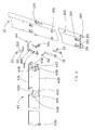
- FIG. 1 is an isometric view of an embodiment of a support assembly supporting photovoltaic panels in accordance with the present disclosure.
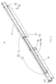
- FIG. 2 is a perspective view of the embodiment of a support unit when packaged and transported in accordance with the present disclosure.
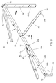
- FIG. 3 is a perspective view of the embodiment of the support unit when used in accordance with the present disclosure.
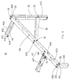
- FIG. 4 is an isometric view of the embodiment of the support unit when used in accordance with the present disclosure.
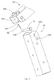
- FIG. 5 is a partially disassembled view of the embodiment of a support beam and a second standing post in accordance with the present disclosure.
- FIG. 6 is a partially disassembled view of the embodiment of the support beam and a first horizontal beam in accordance with the present disclosure.
- a support assembly 1000 for supporting photovoltaic panels 60 comprises a plurality of support units 11 connected one by one.
- Each of the plurality of support units 11 comprises a support beam 10, a pair of standing posts 20, a strengthening bar 30 and at least one horizontal beam 40.
- the pair of standing posts 20, the strengthening bar 30 and the at least one horizontal beam 40 are pivotably mounted on the support beam 10.
- the pair of standing post 20 and the strengthening bar 30 rotate relative to the support beam 10 and are received in the support beam 10 respectively, and the at least one horizontal beam 40 rotates relative to the support beam 10 and is disposed in parallel to the support beam 10, when each of the plurality of support units 11 is packaged and transported.
- the support unit 11 has a regular shape and is convenient for transportation when packaged in this way.
- the at least one horizontal beam 40 is connected to the neighboring support unit 11, the pair of standing posts 20 are unwound and disposed in parallel and the strengthening bar 30 rotates relative to the support beam 10 to constitute a triangle with the support beam 10 and one of the pair of standing posts 20 collectively.
- the support beam 10 comprises a top portion 100 and a pair of side portions 101 perpendicularly extending from two edges of the top portion 100 respectively.
- the top portion 100 and the pair of side portions 101 collectively define a receiving groove 102 used to receive the pair of standing posts 20 and the strengthening bar 30, as shown in FIG. 2 .
- a cross section of the receiving groove 102 is in a U shape.
- the top portion 100 comprises a plurality of latching portions 105 and a plurality of stopper portions 106 to secure the photovoltaic panels 60 thereon.
- the plurality of latching portions 105 and the plurality of stopper portions 106 are punched from the top portion 100 in two parallel rows, two of the plurality of latching portions 105 and two of the plurality of stopper portions 106 are disposed side by side, respectively.
- Each of the pair of the side portions 101 defines a plurality of fixing holes 103 arranged in order.
- the plurality of fixing holes 103 are configured to install the standing post 20 and the strengthening bar 30 by use of connecting shafts 51 onto the support beam 10 respectively.
- inclination of the support beam 10 is adjustable by matching one end of the strengthening bar 30 with different fixing holes 103 in the side portions 101.
- a connecting member 50 is used to pivotably mount the pair of standing posts 20, the strengthening bar 30 and the at least one horizontal beam 40 to the support beam 10 and comprises a connecting shaft 51 and a cotter pin 52.
- the connecting shaft 51 defines a plurality of shaft holes 510. Each of the plurality of shaft holes 510 is a through hole along the radial direction of the connecting shaft 51.
- the cotter pin 52 is inserted into the shaft hole 510 to engage with the connecting shaft 51 to prevent the connecting shaft 51 disengaging.
- the connecting member 50 may be a bolt with a nut or a rivet.
- the pair of standing posts 20 comprise a first standing post 21 and a second standing post 22 in parallel with each other.
- cross sections of the first standing post 21 and the second standing post 22 are in a U-shape, respectively.
- one end of the first standing post 21 is pivotably mounted on the support beam 10, and the other end is securely mounted on a mounting ground.
- the first standing post 21 defines a pair of first securing holes 210 and a plurality of first strengthen holes 212.
- the pair of first securing holes 210 are located on one end of the first standing post 21 and engage with the corresponding fixing hole 103 by use of connecting shafts 51 to pivotably mount the first standing post 21 onto the support beam 10, then the cotter pin 52 is inserted into the shaft hole 510 to prevent the connecting shaft 51 disengaging.
- the first standing post 21 rotates around the connecting shaft 51 and is received in the receiving groove 102 when packaged and/or transported. When used, the first standing post 21 should be rotated along the arrowhead direction as shown in FIG. 3 .
- the plurality of first strengthen holes 212 are evenly apart from each other and arranged in pairs to engage with the strengthening bar 30.
- the strengthening bar 30 with two ends is mounted to the support beam 10 and the first standing post 21 respectively.
- the strengthening bar 30 defines two pairs of second strengthen holes 300.
- the two pairs of second strengthen holes 300 are located on the two ends of the strengthening bar 30 and engage with the corresponding fixing hole 103 and the corresponding first strengthen hole 212 by use of connecting shafts 51 respectively.
- the cotter pin 52 is inserted into the corresponding shaft hole 510 to prevent the corresponding connecting shaft 51 disengaging.
- the support beam 10, the first standing post 21 and the strengthening bar 30 collectively configure a triangle to avoid distortion.
- one end of the strengthening bar 30 rotates around one connecting shaft 51 relative to the support beam 10 by disengaging with the first standing post 21 and is received in the receiving groove 102.
- the strengthening bar 30 should be rotated along the arrowhead direction as shown in FIG. 3 .
- the second standing post 22 and the first standing post 21 rotate around the respective connecting shaft 51 relative to the support beam 10.
- a length of the second standing post 22 is shorter than that of the first standing post 21 so that the support beam 10 is inclined to a certain angle.
- the second standing post 22 defines a pairs of second securing holes 220 and a pair of latching holes 222.
- the pair of the second securing holes 220 is defined in one end of the second standing post 22, and the pair of latching holes 222 are defined beside the pair of the second securing holes 220.
- the connecting shaft 51 passes through the fixing hole 103 and the pair of second securing holes 220 to pivotably mount the second standing post 22 onto the support beam 10, and the cotter pin 52 is inserted into the shaft hole 510 to prevent the connecting shaft 51 disengaging.
- the second standing post 22 rotates around the corresponding connecting shaft 51 relative to the support beam 10 and is received in the receiving groove 102.
- Each side portion 101 of the support beam 10 comprises a latching clip 107.
- the latching clip 107 is located on one end of the support beam 10 neighboring to the second standing post 22.
- the latching clip 107 is bent towards the receiving groove 102.
- the latching clip 107 is integrally formed with the side portion 101.
- each of the pair of the side portions 101 further comprises a plurality of roll portions 104 arranged in order.
- Each of the plurality of roll portions 104 is engaged with the at least one horizontal beam 40 to pivotably mount the at least one horizontal beam 40 onto the support beam 10.
- the plurality of roll portions 104 are integrally formed with the side portion 101.
- the at least one horizontal beam 40 with one end is pivotably mounted to the support beam 10 and the other end is configured to connect to a neighboring support unit 11.
- the at least one horizontal beam 40 comprises a first horizontal beam 41 and a second horizontal beam 42.
- cross sections of the first horizontal beam 41 and the second horizontal beam 42 are in a U shape, respectively.
- the first horizontal beam 41 is pivotably mounted between two neighboring support beams 10.
- the first horizontal beam 41 comprises a first bottom portion 410 and a pair of first side walls 412 bent in parallel from two edges of the first bottom portion 410 respectively.
- the first horizontal beam 41 defines two first double sleeves 414 on two ends thereof and on the same side of the side wall 412.
- the first double sleeve 414 matches with the corresponding roll portion 104 to pivotably connect one end of the first horizontal beam 41 to the support beam 10 by use of the connecting shaft 51.
- the cotter pin 52 is inserted into the corresponding shaft hole 510 to prevent the connecting shaft 51 disengaging.
- the other end of the first horizontal beam 41 is mounted onto the neighboring support beam 10 by the same method.
- the first horizontal beam 41 is mounted between two support units 11 to support the photovoltaic panel 60.
- one end of the first horizontal beam 41 rotates around the corresponding connecting shaft 51 relative to the support beam 10 by removing the other connecting shaft 51 and is folded to get close to the side portion 101 of the support beam 10.
- the first horizontal beam 41 should be rotated along the arrowhead direction as shown in FIG. 3 .
- the first horizontal beam 41 further defines a plurality of first drainage holes 416 on joint portions between the first bottom portion 410 and the pair of first side walls 412 for draining.
- the second horizontal beam 42 is parallel with the first horizontal beam 41 and pivotably mounted between two neighboring support beams 10.
- the second horizontal beam 42 comprises a support portion 43 and a connecting portion 44.
- One end of the support portion 43 is movably mounted on one end of the connecting portion 44 and the other end is mounted on the side portion 101 of the support beam 10.
- the other end of the connecting portion 44 is movably mounted on the side portion 101 of the neighboring support beam 10.
- rotation plane of the connecting portion 44 rotating relative to the support beam 10 is perpendicular to that of the support portion 43 rotating relative to the connecting portion 44, thus, it is convenient to mount or disassemble the support portion 43 and to fold the second horizontal beam 42 close to the support beam 10.
- the support portion 43 comprises a second bottom portion 430, a pair of second side walls 431 bent in parallel from two edges of the second bottom portion 430 respectively and a cover portion 432 parallel with the second bottom portion 430.
- the cover portion 432 is bent along one of the pair of second side walls 431 and is spaced apart from the other of the pair of second side walls 431.
- a receiving portion 433 is cooperatively defined by the second bottom portion 430, the pair of the second side walls 431 and the cover portion 432.
- the receiving portion 433 is used to receive power cords (not shown) from a jack box 61 of the photovoltaic panel 60 (as shown in FIG. 1 ).
- the support portion 43 defines a plurality of latching notches 434 to securely install the photovoltaic panel 60.
- Each of the plurality of latching notches 434 is formed by punching a part of the pair of second side walls 431 and the cover portion 432.
- the power cords are distributed into the receiving portion 433 through the plurality of latching notches 434.
- the second horizontal beam 42 defines a plurality of second watering drainage holes 435 on joint portions between the second bottom portion 430 and the pair of second side walls 431 for draining.
- a single sleeve 436 is defined on one of the pair of second side walls 431 to engage with the corresponding roll portion 104 so as to mount the second horizontal beam 42 on the support beam 10.
- the support assembly 1000 is configured by a plurality of support units 11 to enlarge support area for photovoltaic panels 60 freely.
- a pair of protruding walls 437 are disposed on two side walls 431 of the end of the support portion 43 respectively and define a pair of first through holes 439 correspondingly.
- a protruding post 438 is protruded outwardly from one of the pair of protruding walls 437 towards the receiving portion 433.
- the protruding post 438 and the single sleeve 436 are located on two opposite sides of the second side wall 431.
- the pair of first through holes 439 and the protruding post 438 are engaged with the connecting portion 44 to movably mount the support portion 43 onto the connecting portion 44.
- a cross section of the connecting portion 44 is in a U shape.
- the connecting portion 44 comprises a horizontal double sleeve 440 and a perpendicular double sleeve 441 perpendicular to the horizontal double sleeve 440, and defines a pair of second through holes 442.
- the horizontal double sleeve 440 is located on the bottom of the connecting portion 44 and engaged with the protruding post 438 to pivotably mount the connecting portion 44 onto the support portion 43 by use of the connecting shaft 51.
- the support portion 43 is rotated relative to the connecting portion 44 away from the photovoltaic panel 60.
- the pair of second through holes 442 are located on two sides of the connecting portion 44 and engaged with the pair of first through holes 439 to securely mount the support portion 43 onto the connecting portion 44 by use of the connecting shaft 51. Then, the cotter pin 52 is inserted into the corresponding shaft hole 510 to prevent the connecting shaft 51 disengaging.
- the perpendicular double sleeve 441 is located on the same side of the second horizontal beam 42 with the single sleeve 436. The perpendicular double sleeve 441 matches with the corresponding roll portion 104 to pivotably connect the connecting portion 44 to the side portion 101 by use of the connecting shaft 51, and the cotter pin 52 is inserted into the corresponding shaft hole 510 to prevent the connecting shaft 51 disengaging.
- the connecting portion 44 When packaged and/or transported, the connecting portion 44 is rotated around the connecting shaft 51 with the support portion 43 and the second horizontal beam 42 is folded to be close to the side portion 101.
- the second horizontal beam 42, the second horizontal beam 42 should be rotated along the arrowhead direction as shown in FIG. 3 .
- the first standing post 21, the second standing post 22 and the strengthening bar 30 are pivotably mounted on the support beam 10 by use of the connecting shafts 51 and rotate around the corresponding connecting shaft 51 relative to the support beam 10 to be received into the receiving groove 102 when packaged and/or transported.
- the first standing post 21, the second standing post 22 and the strengthening bar 30 rotate around the corresponding connecting shaft 51 to open each other respectively.
- the first horizontal beam 41 is pivotably mounted on the roll portion 104 by use of the connecting shaft 51 and rotates around the connecting shaft 51 to be folded to get close to the side portion 101 when packaged and/or transported.
- the connecting portion 44 and the support portion 43 are pivotably mounted on the support beam 10 by use of the connecting shaft 51.
- the connecting portion 44 rotates around the corresponding connecting shaft 51 to fold the second horizontal beam 42 to get close to the side portion 101.
- the support portion 43 rotates around the corresponding connecting shaft 51 relative to the connecting portion 44 to distribute the power cords conveniently.
Landscapes
- Engineering & Computer Science (AREA)
- Physics & Mathematics (AREA)
- Life Sciences & Earth Sciences (AREA)
- Sustainable Development (AREA)
- Sustainable Energy (AREA)
- Thermal Sciences (AREA)
- Chemical & Material Sciences (AREA)
- Combustion & Propulsion (AREA)
- Mechanical Engineering (AREA)
- General Engineering & Computer Science (AREA)
- Photovoltaic Devices (AREA)
- Packaging Frangible Articles (AREA)
Abstract
Description
- The present disclosure relates to a photovoltaic panel, and more particularly to a support assembly for photovoltaic panels.
- A support assembly for photovoltaic panels is designed to be foldable to reduce size during transport. Generally, the foldable support assembly is manufactured as individual components, where a great number of bolts are needed to assemble all the components together as finished product. It is often difficult and inconvenient to assemble all components together to form the support assembly. Therefore, how to make the support assembly take smaller space and be installed in convenience is a problem.
-
FIG. 1 is an isometric view of an embodiment of a support assembly supporting photovoltaic panels in accordance with the present disclosure. -
FIG. 2 is a perspective view of the embodiment of a support unit when packaged and transported in accordance with the present disclosure. -
FIG. 3 is a perspective view of the embodiment of the support unit when used in accordance with the present disclosure. -
FIG. 4 is an isometric view of the embodiment of the support unit when used in accordance with the present disclosure. -
FIG. 5 is a partially disassembled view of the embodiment of a support beam and a second standing post in accordance with the present disclosure. -
FIG. 6 is a partially disassembled view of the embodiment of the support beam and a first horizontal beam in accordance with the present disclosure. - Referring to
FIG. 1 andFIG. 2 , asupport assembly 1000 for supportingphotovoltaic panels 60 comprises a plurality ofsupport units 11 connected one by one. Each of the plurality ofsupport units 11 comprises asupport beam 10, a pair of standingposts 20, a strengtheningbar 30 and at least onehorizontal beam 40. The pair of standingposts 20, the strengtheningbar 30 and the at least onehorizontal beam 40 are pivotably mounted on thesupport beam 10. The pair of standingpost 20 and the strengtheningbar 30 rotate relative to thesupport beam 10 and are received in thesupport beam 10 respectively, and the at least onehorizontal beam 40 rotates relative to thesupport beam 10 and is disposed in parallel to thesupport beam 10, when each of the plurality ofsupport units 11 is packaged and transported. Thus, thesupport unit 11 has a regular shape and is convenient for transportation when packaged in this way. When the plurality ofsupport units 11 are assembled, the at least onehorizontal beam 40 is connected to the neighboringsupport unit 11, the pair of standingposts 20 are unwound and disposed in parallel and the strengtheningbar 30 rotates relative to thesupport beam 10 to constitute a triangle with thesupport beam 10 and one of the pair of standingposts 20 collectively. - Referring to
FIG. 3 andFIG. 4 , thesupport beam 10 comprises atop portion 100 and a pair ofside portions 101 perpendicularly extending from two edges of thetop portion 100 respectively. Thetop portion 100 and the pair ofside portions 101 collectively define a receivinggroove 102 used to receive the pair of standingposts 20 and the strengtheningbar 30, as shown inFIG. 2 . In the illustrated embodiment, a cross section of the receivinggroove 102 is in a U shape. Thetop portion 100 comprises a plurality oflatching portions 105 and a plurality ofstopper portions 106 to secure thephotovoltaic panels 60 thereon. In the illustrated embodiment, the plurality oflatching portions 105 and the plurality ofstopper portions 106 are punched from thetop portion 100 in two parallel rows, two of the plurality oflatching portions 105 and two of the plurality ofstopper portions 106 are disposed side by side, respectively. Each of the pair of theside portions 101 defines a plurality offixing holes 103 arranged in order. The plurality offixing holes 103 are configured to install the standingpost 20 and the strengtheningbar 30 by use of connectingshafts 51 onto thesupport beam 10 respectively. In the illustrated embodiment, inclination of thesupport beam 10 is adjustable by matching one end of the strengtheningbar 30 withdifferent fixing holes 103 in theside portions 101. - Referring to
FIG. 2 andFIG. 5 , a connectingmember 50 is used to pivotably mount the pair of standingposts 20, the strengtheningbar 30 and the at least onehorizontal beam 40 to thesupport beam 10 and comprises a connectingshaft 51 and acotter pin 52. The connectingshaft 51 defines a plurality ofshaft holes 510. Each of the plurality ofshaft holes 510 is a through hole along the radial direction of the connectingshaft 51. Thecotter pin 52 is inserted into theshaft hole 510 to engage with the connectingshaft 51 to prevent the connectingshaft 51 disengaging. In the illustrated embodiment, the connectingmember 50 may be a bolt with a nut or a rivet. - Referring to
FIG. 2 , the pair of standingposts 20 comprise a first standingpost 21 and a second standingpost 22 in parallel with each other. In the illustrated embodiment, cross sections of the first standingpost 21 and the second standingpost 22 are in a U-shape, respectively. Referring toFIG. 4 , one end of the first standingpost 21 is pivotably mounted on thesupport beam 10, and the other end is securely mounted on a mounting ground. The first standingpost 21 defines a pair offirst securing holes 210 and a plurality of first strengthenholes 212. The pair of first securingholes 210 are located on one end of the first standingpost 21 and engage with thecorresponding fixing hole 103 by use of connectingshafts 51 to pivotably mount the first standing post 21 onto thesupport beam 10, then thecotter pin 52 is inserted into theshaft hole 510 to prevent the connectingshaft 51 disengaging. The first standingpost 21 rotates around the connectingshaft 51 and is received in the receivinggroove 102 when packaged and/or transported. When used, the first standingpost 21 should be rotated along the arrowhead direction as shown inFIG. 3 . The plurality of first strengthenholes 212 are evenly apart from each other and arranged in pairs to engage with the strengtheningbar 30. - Referring to
FIG. 3 andFIG. 4 , the strengtheningbar 30 with two ends is mounted to thesupport beam 10 and the first standingpost 21 respectively. In the illustrated embodiment, the strengtheningbar 30 defines two pairs of second strengthenholes 300. The two pairs of second strengthenholes 300 are located on the two ends of the strengtheningbar 30 and engage with thecorresponding fixing hole 103 and the corresponding first strengthenhole 212 by use of connectingshafts 51 respectively. Then, thecotter pin 52 is inserted into thecorresponding shaft hole 510 to prevent the corresponding connectingshaft 51 disengaging. Thus, thesupport beam 10, the first standingpost 21 and the strengtheningbar 30 collectively configure a triangle to avoid distortion. When packaged and/or transported, one end of the strengtheningbar 30 rotates around one connectingshaft 51 relative to thesupport beam 10 by disengaging with the first standingpost 21 and is received in thereceiving groove 102. When used, the strengtheningbar 30 should be rotated along the arrowhead direction as shown inFIG. 3 . - Referring to
FIG. 4 , when used, the second standingpost 22 and the first standingpost 21 rotate around the respective connectingshaft 51 relative to thesupport beam 10. In the illustrated embodiment, a length of the second standingpost 22 is shorter than that of the first standingpost 21 so that thesupport beam 10 is inclined to a certain angle. Referring toFIG. 5 , the second standingpost 22 defines a pairs of second securingholes 220 and a pair oflatching holes 222. The pair of thesecond securing holes 220 is defined in one end of the second standingpost 22, and the pair oflatching holes 222 are defined beside the pair of thesecond securing holes 220. The connectingshaft 51 passes through thefixing hole 103 and the pair of second securingholes 220 to pivotably mount the second standingpost 22 onto thesupport beam 10, and thecotter pin 52 is inserted into theshaft hole 510 to prevent the connectingshaft 51 disengaging. When packaged and/or transported, the second standingpost 22 rotates around the corresponding connectingshaft 51 relative to thesupport beam 10 and is received in thereceiving groove 102. Eachside portion 101 of thesupport beam 10 comprises alatching clip 107. Thelatching clip 107 is located on one end of thesupport beam 10 neighboring to the second standingpost 22. Thelatching clip 107 is bent towards thereceiving groove 102. In the illustrated embodiment, thelatching clip 107 is integrally formed with theside portion 101. When used, the second standingpost 22 rotates along the arrowhead direction as shown inFIG. 3 , and thelatching clip 107 engages with thecorresponding latching hole 222 to securely mount the second standingpost 22 onto thesupport beam 10. - Referring to
FIG. 4 , each of the pair of theside portions 101 further comprises a plurality ofroll portions 104 arranged in order. Each of the plurality ofroll portions 104 is engaged with the at least onehorizontal beam 40 to pivotably mount the at least onehorizontal beam 40 onto thesupport beam 10. In the illustrated embodiment, the plurality ofroll portions 104 are integrally formed with theside portion 101. The at least onehorizontal beam 40 with one end is pivotably mounted to thesupport beam 10 and the other end is configured to connect to a neighboringsupport unit 11. The at least onehorizontal beam 40 comprises a firsthorizontal beam 41 and a secondhorizontal beam 42. In the illustrated embodiment, cross sections of the firsthorizontal beam 41 and the secondhorizontal beam 42 are in a U shape, respectively. - The first
horizontal beam 41 is pivotably mounted between two neighboring support beams 10. The firsthorizontal beam 41 comprises afirst bottom portion 410 and a pair offirst side walls 412 bent in parallel from two edges of thefirst bottom portion 410 respectively. The firsthorizontal beam 41 defines two firstdouble sleeves 414 on two ends thereof and on the same side of theside wall 412. The firstdouble sleeve 414 matches with thecorresponding roll portion 104 to pivotably connect one end of the firsthorizontal beam 41 to thesupport beam 10 by use of the connectingshaft 51. Then thecotter pin 52 is inserted into the correspondingshaft hole 510 to prevent the connectingshaft 51 disengaging. The other end of the firsthorizontal beam 41 is mounted onto the neighboringsupport beam 10 by the same method. Thus, the firsthorizontal beam 41 is mounted between twosupport units 11 to support thephotovoltaic panel 60. When packaged and/or transported, one end of the firsthorizontal beam 41 rotates around the corresponding connectingshaft 51 relative to thesupport beam 10 by removing the other connectingshaft 51 and is folded to get close to theside portion 101 of thesupport beam 10. When used, the firsthorizontal beam 41 should be rotated along the arrowhead direction as shown inFIG. 3 . The firsthorizontal beam 41 further defines a plurality of first drainage holes 416 on joint portions between thefirst bottom portion 410 and the pair offirst side walls 412 for draining. - Referring to
FIG. 4 , the secondhorizontal beam 42 is parallel with the firsthorizontal beam 41 and pivotably mounted between two neighboring support beams 10. The secondhorizontal beam 42 comprises asupport portion 43 and a connectingportion 44. One end of thesupport portion 43 is movably mounted on one end of the connectingportion 44 and the other end is mounted on theside portion 101 of thesupport beam 10. The other end of the connectingportion 44 is movably mounted on theside portion 101 of the neighboringsupport beam 10. In the illustrated embodiment, rotation plane of the connectingportion 44 rotating relative to thesupport beam 10 is perpendicular to that of thesupport portion 43 rotating relative to the connectingportion 44, thus, it is convenient to mount or disassemble thesupport portion 43 and to fold the secondhorizontal beam 42 close to thesupport beam 10. - Referring to
FIG. 6 , thesupport portion 43 comprises asecond bottom portion 430, a pair ofsecond side walls 431 bent in parallel from two edges of thesecond bottom portion 430 respectively and acover portion 432 parallel with thesecond bottom portion 430. Thecover portion 432 is bent along one of the pair ofsecond side walls 431 and is spaced apart from the other of the pair ofsecond side walls 431. A receivingportion 433 is cooperatively defined by thesecond bottom portion 430, the pair of thesecond side walls 431 and thecover portion 432. The receivingportion 433 is used to receive power cords (not shown) from ajack box 61 of the photovoltaic panel 60 (as shown inFIG. 1 ). Thesupport portion 43 defines a plurality of latchingnotches 434 to securely install thephotovoltaic panel 60. Each of the plurality of latchingnotches 434 is formed by punching a part of the pair ofsecond side walls 431 and thecover portion 432. The power cords are distributed into the receivingportion 433 through the plurality of latchingnotches 434. The secondhorizontal beam 42 defines a plurality of second watering drainage holes 435 on joint portions between thesecond bottom portion 430 and the pair ofsecond side walls 431 for draining. - A
single sleeve 436 is defined on one of the pair ofsecond side walls 431 to engage with thecorresponding roll portion 104 so as to mount the secondhorizontal beam 42 on thesupport beam 10. Thus, thesupport assembly 1000 is configured by a plurality ofsupport units 11 to enlarge support area forphotovoltaic panels 60 freely. A pair of protrudingwalls 437 are disposed on twoside walls 431 of the end of thesupport portion 43 respectively and define a pair of first throughholes 439 correspondingly. A protrudingpost 438 is protruded outwardly from one of the pair of protrudingwalls 437 towards the receivingportion 433. The protrudingpost 438 and thesingle sleeve 436 are located on two opposite sides of thesecond side wall 431. The pair of first throughholes 439 and the protrudingpost 438 are engaged with the connectingportion 44 to movably mount thesupport portion 43 onto the connectingportion 44. - In the illustrated embodiment, a cross section of the connecting
portion 44 is in a U shape. The connectingportion 44 comprises a horizontaldouble sleeve 440 and a perpendiculardouble sleeve 441 perpendicular to the horizontaldouble sleeve 440, and defines a pair of second throughholes 442. The horizontaldouble sleeve 440 is located on the bottom of the connectingportion 44 and engaged with the protrudingpost 438 to pivotably mount the connectingportion 44 onto thesupport portion 43 by use of the connectingshaft 51. To distribute the power cords (not shown), thesupport portion 43 is rotated relative to the connectingportion 44 away from thephotovoltaic panel 60. The pair of second throughholes 442 are located on two sides of the connectingportion 44 and engaged with the pair of first throughholes 439 to securely mount thesupport portion 43 onto the connectingportion 44 by use of the connectingshaft 51. Then, thecotter pin 52 is inserted into the correspondingshaft hole 510 to prevent the connectingshaft 51 disengaging. The perpendiculardouble sleeve 441 is located on the same side of the secondhorizontal beam 42 with thesingle sleeve 436. The perpendiculardouble sleeve 441 matches with thecorresponding roll portion 104 to pivotably connect the connectingportion 44 to theside portion 101 by use of the connectingshaft 51, and thecotter pin 52 is inserted into the correspondingshaft hole 510 to prevent the connectingshaft 51 disengaging. When packaged and/or transported, the connectingportion 44 is rotated around the connectingshaft 51 with thesupport portion 43 and the secondhorizontal beam 42 is folded to be close to theside portion 101. When used, the secondhorizontal beam 42, the secondhorizontal beam 42 should be rotated along the arrowhead direction as shown inFIG. 3 . - The first standing
post 21, the second standingpost 22 and the strengtheningbar 30 are pivotably mounted on thesupport beam 10 by use of the connectingshafts 51 and rotate around the corresponding connectingshaft 51 relative to thesupport beam 10 to be received into the receivinggroove 102 when packaged and/or transported. Similarly, the first standingpost 21, the second standingpost 22 and the strengtheningbar 30 rotate around the corresponding connectingshaft 51 to open each other respectively. The firsthorizontal beam 41 is pivotably mounted on theroll portion 104 by use of the connectingshaft 51 and rotates around the connectingshaft 51 to be folded to get close to theside portion 101 when packaged and/or transported. The connectingportion 44 and thesupport portion 43 are pivotably mounted on thesupport beam 10 by use of the connectingshaft 51. The connectingportion 44 rotates around the corresponding connectingshaft 51 to fold the secondhorizontal beam 42 to get close to theside portion 101. Thesupport portion 43 rotates around the corresponding connectingshaft 51 relative to the connectingportion 44 to distribute the power cords conveniently. - Although the features and elements of the present disclosure are described as embodiments in particular combinations, each feature or element is used alone or in other various combinations within the principles of the present disclosure to the full extent indicated by the broad general meaning of the terms in which the appended claims are expressed.
Claims (19)
- A support assembly for photovoltaic panels, the support assembly comprising a plurality of support units connected one by one, each of the plurality of support units comprising:a support beam, comprising a top portion and a pair of side portions perpendicularly extending from two edges of the top portion respectively, the top portion and the pair of side portions collectively defining a receiving groove;a pair of standing posts, each with one end pivotably mounted on the support beam;a strengthening bar, with two ends mounted to the support beam and one of the pair of standing posts respectively; andat least one horizontal beam, with one end pivotably mounted to the support beam, and the other end being configured to connect to a neighboring support unit;wherein the pair of standing posts and the strengthening bar rotate relative to the support beam and are received in the receiving groove respectively, and the at least one horizontal beam rotates relative to the support beam and is disposed in parallel to the support beam, when each of the plurality of support units is packaged;when the support units are assembled, the at least one horizontal beam is connected to the neighboring support unit, the pair of standing posts are unwound and disposed in parallel and, the strengthening bar rotates relative to the support beam to constitute a triangle with the support beam and one of the pair of standing posts collectively.
- The support assembly as claimed in claim 1, wherein each of the pair of the side portions defines a plurality of fixing holes arranged in order, the plurality of fixing holes are configured to install the standing post and the strengthening bar onto the support beam respectively.
- The support assembly as claimed in claim 2, wherein inclination of the support beam is adjustable by matching one end of the strengthening bar with different fixing holes in the side portions.
- The support assembly as claimed in claim 3, wherein the top portion comprises a plurality of latching portions and a plurality of stopper portions to secure the photovoltaic panels.
- The support assembly as claimed in claim 4, wherein the plurality of latching portions and the plurality of stopper portions are punched from the top portion in two parallel rows.
- The support assembly as claimed in any preceding claim, wherein a connect member is used to pivotably mount the pair of standing posts, the strengthening bar and the at least one horizontal beam to the support beam and comprises a connecting shaft and a cotter pin, the connecting shaft defines a plurality of shaft holes to engage with the cotter pins to prevent the connecting shaft disengaging.
- The support assembly as claimed in claim 6, wherein each of the plurality of shaft holes is a through hole along the radial direction of the connecting shaft.
- The support assembly as claimed in any preceding claim, wherein the pair of standing posts comprise a first standing post and a second standing post in parallel with each other, cross sections of the first standing post and the second standing post are in a U-shape, respectively.
- The support assembly as claimed in claim 8, wherein a length of the second standing post is shorter than that of the first standing post so that the support beam is inclined to a certain angle.
- The support assembly as claimed in claim 9, wherein the second standing post defines a pair of latching holes, each of the pair of side portions comprises a latching clip engaging with the corresponding latching hole to securely mount the second standing post onto the support beam.
- The support assembly as claimed in any preceding claim, wherein the at least one horizontal beam comprises a first horizontal bean and a second horizontal beam in parallel with each other, cross sections of the first horizontal beam and the second horizontal beam are in a U shape, respectively.
- The support assembly as claimed in claim 11, wherein each of the pair of the side portions comprises a plurality of roll portions arranged in orders, the first horizontal beam defines two first double sleeves on two ends thereof, the first double sleeves matches with the corresponding roll portion to pivotably connect the first horizontal beam to the support beam.
- The support assembly as claimed in claim 12, wherein the plurality of roll portions are integrally formed with the side portion.
- The support assembly as claimed in claim 13, wherein the second horizontal beam comprises a support portion and a connecting portion, the support portion is mounted between the support beam and the connecting portion, the connecting portion is mounted between the support portion and the neighboring support beam.
- The support assembly as claimed in claim 14, wherein rotation plane of the connecting portion rotating relative to the support beam is perpendicular to that of the support portion rotating relative to the connecting portion.
- The support assembly as claimed in claim 15, wherein the support portion comprises a receiving portion to receive power cords of the photovoltaic panel.
- The support assembly as claimed in claim 16, wherein the support portion comprises a protruding post protruded towards the receiving portion, the connecting portion comprises a horizontal double sleeve to engage with the protruding post to pivotably mount the connecting portion onto the support portion.
- The support assembly as claimed in claim 17, wherein the connecting portion further comprises a perpendicular double sleeve perpendicular to the horizontal double sleeve and matching with the corresponding roll portion to pivotably connect the connecting portion to the support beam, the support portion defines a single sleeve engaged with the corresponding roll portion to mount the second horizontal beam on the support beam.
- The support assembly as claimed in claim 18, wherein the first horizontal beam defines a plurality of first watering drainage holes and the second horizontal beam defines a plurality of second watering drainage holes for draining.
Applications Claiming Priority (1)
| Application Number | Priority Date | Filing Date | Title |
|---|---|---|---|
| CN201020230857XU CN201820766U (en) | 2010-06-21 | 2010-06-21 | Solar photovoltaic panel mounting bracket |
Publications (3)
| Publication Number | Publication Date |
|---|---|
| EP2398065A2 true EP2398065A2 (en) | 2011-12-21 |
| EP2398065A3 EP2398065A3 (en) | 2015-10-28 |
| EP2398065B1 EP2398065B1 (en) | 2019-12-25 |
Family
ID=43918710
Family Applications (1)
| Application Number | Title | Priority Date | Filing Date |
|---|---|---|---|
| EP10193176.4A Active EP2398065B1 (en) | 2010-06-21 | 2010-11-30 | Support assembly for photovoltaic panels |
Country Status (3)
| Country | Link |
|---|---|
| US (1) | US9115915B2 (en) |
| EP (1) | EP2398065B1 (en) |
| CN (1) | CN201820766U (en) |
Cited By (5)
| Publication number | Priority date | Publication date | Assignee | Title |
|---|---|---|---|---|
| WO2013153200A3 (en) * | 2012-04-13 | 2015-01-22 | Richard Brink Gmbh & Co. Kg | Kit for a device for retaining solar elements |
| CN105490623A (en) * | 2015-12-16 | 2016-04-13 | 常熟高嘉能源科技有限公司 | High-strength photovoltaic module bracket |
| CN107477053A (en) * | 2017-09-19 | 2017-12-15 | 中广核研究院有限公司 | Height support beam auxiliary member |
| EP4148339A1 (en) * | 2021-09-13 | 2023-03-15 | CEP-IP Ltd | Assembly for a portable solar energy system |
| EP4148979A1 (en) * | 2021-09-13 | 2023-03-15 | CEP-IP Ltd | Foldable photovoltaic assembly for a portable solar energy system |
Families Citing this family (40)
| Publication number | Priority date | Publication date | Assignee | Title |
|---|---|---|---|---|
| US8534007B2 (en) * | 2009-02-24 | 2013-09-17 | Sunpower Corporation | Photovoltaic assemblies and methods for transporting |
| US8413824B2 (en) * | 2009-11-23 | 2013-04-09 | Albert Louis Cabassa | Vertically-oriented folding wire caddy |
| US9462734B2 (en) | 2010-04-27 | 2016-10-04 | Alion Energy, Inc. | Rail systems and methods for installation and operation of photovoltaic arrays |
| US9343592B2 (en) | 2010-08-03 | 2016-05-17 | Alion Energy, Inc. | Electrical interconnects for photovoltaic modules and methods thereof |
| US20120145848A1 (en) * | 2010-12-10 | 2012-06-14 | David Schuff | Pier cap cleat |
| US9641123B2 (en) | 2011-03-18 | 2017-05-02 | Alion Energy, Inc. | Systems for mounting photovoltaic modules |
| WO2012167775A2 (en) * | 2011-06-08 | 2012-12-13 | Schletter Gmbh | Assembly of a stand for pv modules |
| TWI433333B (en) * | 2011-07-05 | 2014-04-01 | Au Optronics Corp | Solar panel module |
| CN102983184B (en) * | 2011-09-05 | 2015-07-08 | 日轻金Act株式会社 | Solar panel stand |
| CN102983183A (en) * | 2011-09-05 | 2013-03-20 | 杜邦太阳能有限公司 | Adjustable mounting structure of solar energy system |
| US9003726B2 (en) * | 2011-11-14 | 2015-04-14 | The RAQ, LLC | System and method for establishing a self-aligning mounting system for mounting photovoltaic modules |
| CN102494421B (en) * | 2011-12-01 | 2013-11-13 | 苏州瑞得恩光能科技有限公司 | Guide rail installation frame |
| CN103187463A (en) * | 2011-12-29 | 2013-07-03 | 富昱能源科技(昆山)有限公司 | Support device |
| WO2013138444A1 (en) * | 2012-03-15 | 2013-09-19 | Magna International Inc. | Solar panel mounting structure |
| US9352941B2 (en) | 2012-03-20 | 2016-05-31 | Alion Energy, Inc. | Gantry crane vehicles and methods for photovoltaic arrays |
| IN2014DN10302A (en) * | 2012-05-03 | 2015-08-07 | Changzhou Trina Solar Energy | |
| CN104412026A (en) * | 2012-05-16 | 2015-03-11 | 阿利昂能源公司 | Rotatable support systems for photovoltaic modules and methods thereof |
| US8936164B2 (en) * | 2012-07-06 | 2015-01-20 | Industrial Origami, Inc. | Solar panel rack |
| CN102916063A (en) * | 2012-10-15 | 2013-02-06 | 东莞市中海光电材料有限公司 | Solar panel assembly, solar panel mounting system and mounting method thereof |
| CN103056861A (en) * | 2013-01-23 | 2013-04-24 | 上海理工大学 | Detachable and foldable tool cart |
| CN103050893A (en) * | 2013-01-24 | 2013-04-17 | 青岛乾程电子科技有限公司 | Electric ring main unit terminal device |
| JP5499194B1 (en) * | 2013-02-12 | 2014-05-21 | 株式会社 沢木組 | Solar panel mounting base |
| AU2014315407B2 (en) | 2013-09-05 | 2018-12-13 | Alion Energy, Inc. | Systems, vehicles, and methods for maintaining rail-based arrays of photovoltaic modules |
| US9453660B2 (en) | 2013-09-11 | 2016-09-27 | Alion Energy, Inc. | Vehicles and methods for magnetically managing legs of rail-based photovoltaic modules during installation |
| JP6146880B2 (en) * | 2014-06-23 | 2017-06-14 | 株式会社ソーラーリソースジャパン | Solar panel mount |
| JP6478383B2 (en) * | 2014-09-17 | 2019-03-06 | 株式会社タナック | Module mounting frame and frame set |
| JP6442739B2 (en) * | 2014-11-21 | 2018-12-26 | 日本エフ・アール・ピー株式会社 | Support assembly for solar panels |
| US10171027B2 (en) | 2015-03-02 | 2019-01-01 | Sunpower Corporation | Photovoltaic module mount |
| US20160365823A1 (en) * | 2015-05-18 | 2016-12-15 | Alion Energy, Inc. | Systems and methods for mounting photovoltaic modules |
| WO2017044566A1 (en) | 2015-09-11 | 2017-03-16 | Alion Energy, Inc. | Wind screens for photovoltaic arrays and methods thereof |
| US20170126168A1 (en) * | 2015-11-03 | 2017-05-04 | Gamechange Solar Llc | Grid-lite roof system for solar panel installations |
| JP6698331B2 (en) * | 2015-12-14 | 2020-05-27 | アルファブロス株式会社 | Solar panel mount |
| IT201800004039A1 (en) * | 2018-03-28 | 2019-09-28 | Elianto S R L | SUPPORT STRUCTURE OF A THERMODYNAMIC LINEAR CONCENTRATION SOLAR SYSTEM EQUIPPED WITH FRESNEL REFLECTORS |
| CN110601641B (en) * | 2019-09-17 | 2022-12-20 | 江苏凯撒型材科技有限公司 | Standardized photovoltaic mounting system |
| ES1248271Y (en) * | 2020-05-07 | 2020-09-14 | Manonelles Montserrat Bonjoch | SUPPORT OF PHOTOVOLTAIC MODULES |
| CN112923584B (en) * | 2021-03-25 | 2022-03-04 | 中国科学院西北生态环境资源研究院 | Photo-convergent anti-freeze-heave heat-gathering device and its roadbed |
| US11817814B2 (en) * | 2021-04-28 | 2023-11-14 | James E. Straeter | Ground mounted solar power assembly |
| EP4148984A1 (en) * | 2021-09-13 | 2023-03-15 | CEP-IP Ltd | Photovoltaic assembly for a portable solar energy system |
| CN114135746B (en) * | 2021-12-01 | 2024-05-07 | 四川波凡同创机器人有限公司 | Wooden tripod, production method and production line |
| DE202022105414U1 (en) | 2022-09-27 | 2022-10-06 | König GmbH & Co. KG | Supporting structure assembly system for photovoltaic modules |
Family Cites Families (12)
| Publication number | Priority date | Publication date | Assignee | Title |
|---|---|---|---|---|
| US1714698A (en) * | 1926-11-08 | 1929-05-28 | Frank M Stoll | Latch mechanism for hinge members |
| US4269173A (en) * | 1978-04-27 | 1981-05-26 | Libbey-Owens-Ford Company | System for mounting solar collector panels |
| JPS6140063A (en) * | 1984-07-31 | 1986-02-26 | Toshiba Electric Equip Corp | Solar cell mounting apparatus |
| GB2238827B (en) * | 1989-12-08 | 1994-03-30 | Heywood Williams Ltd | Hinge |
| JPH09235844A (en) * | 1996-02-29 | 1997-09-09 | Shiroki Corp | Solar cell mounting structure |
| BE1013890A3 (en) * | 2001-01-04 | 2002-11-05 | Verheyen Hugo Gerard | Work table. |
| DE102004023043B4 (en) * | 2004-05-06 | 2007-01-18 | Doko, Gilbert, Dr.-Ing. | Transportable plant for solar power generation |
| US20080030029A1 (en) * | 2006-06-19 | 2008-02-07 | Mcginnis Glenn M | Double hung entry door bracing system |
| US7717376B2 (en) * | 2006-10-17 | 2010-05-18 | Sparks Jr Douglas M | Bracket devices and systems |
| CA2761367A1 (en) * | 2008-05-08 | 2009-11-12 | Solar Power, Inc. | Flat roof mounted solar panel support system |
| US8256169B2 (en) * | 2009-03-20 | 2012-09-04 | Northern States Metals Company | Support system for solar panels |
| US8272189B2 (en) * | 2009-04-29 | 2012-09-25 | Wuxi Suntech Power Co., Ltd. | PV module frame, PV module and installation system thereof |
-
2010
- 2010-06-21 CN CN201020230857XU patent/CN201820766U/en not_active Expired - Lifetime
- 2010-09-23 US US12/888,416 patent/US9115915B2/en active Active
- 2010-11-30 EP EP10193176.4A patent/EP2398065B1/en active Active
Non-Patent Citations (1)
| Title |
|---|
| None |
Cited By (8)
| Publication number | Priority date | Publication date | Assignee | Title |
|---|---|---|---|---|
| WO2013153200A3 (en) * | 2012-04-13 | 2015-01-22 | Richard Brink Gmbh & Co. Kg | Kit for a device for retaining solar elements |
| CN105490623A (en) * | 2015-12-16 | 2016-04-13 | 常熟高嘉能源科技有限公司 | High-strength photovoltaic module bracket |
| CN107477053A (en) * | 2017-09-19 | 2017-12-15 | 中广核研究院有限公司 | Height support beam auxiliary member |
| EP4148339A1 (en) * | 2021-09-13 | 2023-03-15 | CEP-IP Ltd | Assembly for a portable solar energy system |
| EP4148979A1 (en) * | 2021-09-13 | 2023-03-15 | CEP-IP Ltd | Foldable photovoltaic assembly for a portable solar energy system |
| WO2023037001A1 (en) * | 2021-09-13 | 2023-03-16 | CEP-IP Ltd | Foldable photovoltaic assembly for a portable solar energy system |
| WO2023037003A1 (en) * | 2021-09-13 | 2023-03-16 | CEP-IP Ltd | Assembly for a portable solar energy system |
| US20240396492A1 (en) * | 2021-09-13 | 2024-11-28 | CEP-IP Ltd | Assembly for a portable solar energy system |
Also Published As
| Publication number | Publication date |
|---|---|
| EP2398065A3 (en) | 2015-10-28 |
| US20110309215A1 (en) | 2011-12-22 |
| EP2398065B1 (en) | 2019-12-25 |
| CN201820766U (en) | 2011-05-04 |
| US9115915B2 (en) | 2015-08-25 |
Similar Documents
| Publication | Publication Date | Title |
|---|---|---|
| US9115915B2 (en) | Support assembly for photovoltaic panels | |
| CN106175134B (en) | Utility bracket with end supports including folding cross members | |
| US10508005B2 (en) | Assembly for lifting or supporting a load, and members and connectors for use in same | |
| US20140291462A1 (en) | System for mounting solar modules | |
| US20180087287A1 (en) | Wind Turbine Tower Section, Wind Turbine Tower and Assembly Method | |
| EP3212358B1 (en) | Link-plate connection for monopole reinforcing bars | |
| US20040111999A1 (en) | Foldable support structure with hinged wall members | |
| US20130270332A1 (en) | Modular Panel-Packing Box | |
| GB2543581A (en) | Single axis solar tracking assembly and method of installing such single axis solar tracking assembly | |
| US6283045B1 (en) | Foldable table | |
| KR101583141B1 (en) | Foldable outside article institution a stand for airconditioner | |
| CN106677510B (en) | Operation platform, tower section of thick bamboo lamellar body, tower section of thick bamboo section, tower section of thick bamboo and wind generating set | |
| US20210115903A1 (en) | Wind turbine mast section, wind turbine mast and assembly method | |
| US20190203492A1 (en) | Banner frame with anchor stakes | |
| CN112969852B (en) | Wind turbine mast section, wind turbine mast and assembly method | |
| CA3015262C (en) | Play structure and bracket for play structure | |
| JP2008174956A (en) | Support structure | |
| WO2019057669A1 (en) | Shelter comprising a plurality of modules suitable for being solidly connected together to form a gridshell lattice structure | |
| EP2843157A1 (en) | A modular staging system with a trolley | |
| AU2016343293A1 (en) | A portable frame for supporting a solar panel | |
| US20250374467A1 (en) | Mounting assemblies for remote radio units | |
| KR20130005096U (en) | Big type tent frame utilizing connecting adapter | |
| JP2007169025A (en) | Wheel conveyor | |
| KR101172993B1 (en) | Folding Desk | |
| KR20120013561A (en) | Adjustable rack structure |
Legal Events
| Date | Code | Title | Description |
|---|---|---|---|
| AK | Designated contracting states |
Kind code of ref document: A2 Designated state(s): AL AT BE BG CH CY CZ DE DK EE ES FI FR GB GR HR HU IE IS IT LI LT LU LV MC MK MT NL NO PL PT RO RS SE SI SK SM TR |
|
| AX | Request for extension of the european patent |
Extension state: BA ME |
|
| PUAI | Public reference made under article 153(3) epc to a published international application that has entered the european phase |
Free format text: ORIGINAL CODE: 0009012 |
|
| PUAL | Search report despatched |
Free format text: ORIGINAL CODE: 0009013 |
|
| AK | Designated contracting states |
Kind code of ref document: A3 Designated state(s): AL AT BE BG CH CY CZ DE DK EE ES FI FR GB GR HR HU IE IS IT LI LT LU LV MC MK MT NL NO PL PT RO RS SE SI SK SM TR |
|
| AX | Request for extension of the european patent |
Extension state: BA ME |
|
| 17P | Request for examination filed |
Effective date: 20160426 |
|
| RBV | Designated contracting states (corrected) |
Designated state(s): AL AT BE BG CH CY CZ DE DK EE ES FI FR GB GR HR HU IE IS IT LI LT LU LV MC MK MT NL NO PL PT RO RS SE SI SK SM TR |
|
| STAA | Information on the status of an ep patent application or granted ep patent |
Free format text: STATUS: EXAMINATION IS IN PROGRESS |
|
| 17Q | First examination report despatched |
Effective date: 20180718 |
|
| REG | Reference to a national code |
Ref country code: DE Ref legal event code: R079 Ref document number: 602010062494 Country of ref document: DE Free format text: PREVIOUS MAIN CLASS: H01L0031042000 Ipc: H02S0030200000 |
|
| GRAP | Despatch of communication of intention to grant a patent |
Free format text: ORIGINAL CODE: EPIDOSNIGR1 |
|
| STAA | Information on the status of an ep patent application or granted ep patent |
Free format text: STATUS: GRANT OF PATENT IS INTENDED |
|
| RIC1 | Information provided on ipc code assigned before grant |
Ipc: F24S 25/65 20180101ALI20190716BHEP Ipc: H02S 30/20 20140101AFI20190716BHEP |
|
| RIC1 | Information provided on ipc code assigned before grant |
Ipc: F24S 25/632 20180101ALI20190729BHEP Ipc: F24S 25/12 20180101ALI20190729BHEP Ipc: H02S 20/10 20140101ALI20190729BHEP Ipc: F24S 25/65 20180101ALI20190729BHEP Ipc: H02S 30/20 20140101AFI20190729BHEP |
|
| INTG | Intention to grant announced |
Effective date: 20190813 |
|
| RIN1 | Information on inventor provided before grant (corrected) |
Inventor name: WANG, REN Inventor name: LU, KAI-MING |
|
| GRAS | Grant fee paid |
Free format text: ORIGINAL CODE: EPIDOSNIGR3 |
|
| GRAA | (expected) grant |
Free format text: ORIGINAL CODE: 0009210 |
|
| STAA | Information on the status of an ep patent application or granted ep patent |
Free format text: STATUS: THE PATENT HAS BEEN GRANTED |
|
| AK | Designated contracting states |
Kind code of ref document: B1 Designated state(s): AL AT BE BG CH CY CZ DE DK EE ES FI FR GB GR HR HU IE IS IT LI LT LU LV MC MK MT NL NO PL PT RO RS SE SI SK SM TR |
|
| REG | Reference to a national code |
Ref country code: GB Ref legal event code: FG4D |
|
| REG | Reference to a national code |
Ref country code: CH Ref legal event code: EP |
|
| REG | Reference to a national code |
Ref country code: AT Ref legal event code: REF Ref document number: 1218254 Country of ref document: AT Kind code of ref document: T Effective date: 20200115 |
|
| REG | Reference to a national code |
Ref country code: DE Ref legal event code: R096 Ref document number: 602010062494 Country of ref document: DE |
|
| REG | Reference to a national code |
Ref country code: IE Ref legal event code: FG4D |
|
| REG | Reference to a national code |
Ref country code: CH Ref legal event code: NV Representative=s name: RENTSCH PARTNER AG, CH |
|
| RAP2 | Party data changed (patent owner data changed or rights of a patent transferred) |
Owner name: HON HAI PRECISION INDUSTRY CO., LTD. Owner name: HONG FU JIN PRECISION INDUSTRY (SHENZHEN) CO., LTD. |
|
| REG | Reference to a national code |
Ref country code: NL Ref legal event code: MP Effective date: 20191225 |
|
| PG25 | Lapsed in a contracting state [announced via postgrant information from national office to epo] |
Ref country code: LV Free format text: LAPSE BECAUSE OF FAILURE TO SUBMIT A TRANSLATION OF THE DESCRIPTION OR TO PAY THE FEE WITHIN THE PRESCRIBED TIME-LIMIT Effective date: 20191225 Ref country code: SE Free format text: LAPSE BECAUSE OF FAILURE TO SUBMIT A TRANSLATION OF THE DESCRIPTION OR TO PAY THE FEE WITHIN THE PRESCRIBED TIME-LIMIT Effective date: 20191225 Ref country code: GR Free format text: LAPSE BECAUSE OF FAILURE TO SUBMIT A TRANSLATION OF THE DESCRIPTION OR TO PAY THE FEE WITHIN THE PRESCRIBED TIME-LIMIT Effective date: 20200326 Ref country code: NO Free format text: LAPSE BECAUSE OF FAILURE TO SUBMIT A TRANSLATION OF THE DESCRIPTION OR TO PAY THE FEE WITHIN THE PRESCRIBED TIME-LIMIT Effective date: 20200325 Ref country code: LT Free format text: LAPSE BECAUSE OF FAILURE TO SUBMIT A TRANSLATION OF THE DESCRIPTION OR TO PAY THE FEE WITHIN THE PRESCRIBED TIME-LIMIT Effective date: 20191225 Ref country code: BG Free format text: LAPSE BECAUSE OF FAILURE TO SUBMIT A TRANSLATION OF THE DESCRIPTION OR TO PAY THE FEE WITHIN THE PRESCRIBED TIME-LIMIT Effective date: 20200325 Ref country code: FI Free format text: LAPSE BECAUSE OF FAILURE TO SUBMIT A TRANSLATION OF THE DESCRIPTION OR TO PAY THE FEE WITHIN THE PRESCRIBED TIME-LIMIT Effective date: 20191225 |
|
| REG | Reference to a national code |
Ref country code: LT Ref legal event code: MG4D |
|
| PG25 | Lapsed in a contracting state [announced via postgrant information from national office to epo] |
Ref country code: HR Free format text: LAPSE BECAUSE OF FAILURE TO SUBMIT A TRANSLATION OF THE DESCRIPTION OR TO PAY THE FEE WITHIN THE PRESCRIBED TIME-LIMIT Effective date: 20191225 Ref country code: RS Free format text: LAPSE BECAUSE OF FAILURE TO SUBMIT A TRANSLATION OF THE DESCRIPTION OR TO PAY THE FEE WITHIN THE PRESCRIBED TIME-LIMIT Effective date: 20191225 |
|
| PG25 | Lapsed in a contracting state [announced via postgrant information from national office to epo] |
Ref country code: AL Free format text: LAPSE BECAUSE OF FAILURE TO SUBMIT A TRANSLATION OF THE DESCRIPTION OR TO PAY THE FEE WITHIN THE PRESCRIBED TIME-LIMIT Effective date: 20191225 |
|
| PG25 | Lapsed in a contracting state [announced via postgrant information from national office to epo] |
Ref country code: EE Free format text: LAPSE BECAUSE OF FAILURE TO SUBMIT A TRANSLATION OF THE DESCRIPTION OR TO PAY THE FEE WITHIN THE PRESCRIBED TIME-LIMIT Effective date: 20191225 Ref country code: PT Free format text: LAPSE BECAUSE OF FAILURE TO SUBMIT A TRANSLATION OF THE DESCRIPTION OR TO PAY THE FEE WITHIN THE PRESCRIBED TIME-LIMIT Effective date: 20200520 Ref country code: NL Free format text: LAPSE BECAUSE OF FAILURE TO SUBMIT A TRANSLATION OF THE DESCRIPTION OR TO PAY THE FEE WITHIN THE PRESCRIBED TIME-LIMIT Effective date: 20191225 Ref country code: RO Free format text: LAPSE BECAUSE OF FAILURE TO SUBMIT A TRANSLATION OF THE DESCRIPTION OR TO PAY THE FEE WITHIN THE PRESCRIBED TIME-LIMIT Effective date: 20191225 Ref country code: CZ Free format text: LAPSE BECAUSE OF FAILURE TO SUBMIT A TRANSLATION OF THE DESCRIPTION OR TO PAY THE FEE WITHIN THE PRESCRIBED TIME-LIMIT Effective date: 20191225 |
|
| PG25 | Lapsed in a contracting state [announced via postgrant information from national office to epo] |
Ref country code: SM Free format text: LAPSE BECAUSE OF FAILURE TO SUBMIT A TRANSLATION OF THE DESCRIPTION OR TO PAY THE FEE WITHIN THE PRESCRIBED TIME-LIMIT Effective date: 20191225 Ref country code: SK Free format text: LAPSE BECAUSE OF FAILURE TO SUBMIT A TRANSLATION OF THE DESCRIPTION OR TO PAY THE FEE WITHIN THE PRESCRIBED TIME-LIMIT Effective date: 20191225 Ref country code: IS Free format text: LAPSE BECAUSE OF FAILURE TO SUBMIT A TRANSLATION OF THE DESCRIPTION OR TO PAY THE FEE WITHIN THE PRESCRIBED TIME-LIMIT Effective date: 20200425 |
|
| REG | Reference to a national code |
Ref country code: DE Ref legal event code: R097 Ref document number: 602010062494 Country of ref document: DE |
|
| PG25 | Lapsed in a contracting state [announced via postgrant information from national office to epo] |
Ref country code: DK Free format text: LAPSE BECAUSE OF FAILURE TO SUBMIT A TRANSLATION OF THE DESCRIPTION OR TO PAY THE FEE WITHIN THE PRESCRIBED TIME-LIMIT Effective date: 20191225 Ref country code: ES Free format text: LAPSE BECAUSE OF FAILURE TO SUBMIT A TRANSLATION OF THE DESCRIPTION OR TO PAY THE FEE WITHIN THE PRESCRIBED TIME-LIMIT Effective date: 20191225 |
|
| PLBE | No opposition filed within time limit |
Free format text: ORIGINAL CODE: 0009261 |
|
| STAA | Information on the status of an ep patent application or granted ep patent |
Free format text: STATUS: NO OPPOSITION FILED WITHIN TIME LIMIT |
|
| REG | Reference to a national code |
Ref country code: AT Ref legal event code: MK05 Ref document number: 1218254 Country of ref document: AT Kind code of ref document: T Effective date: 20191225 |
|
| PG25 | Lapsed in a contracting state [announced via postgrant information from national office to epo] |
Ref country code: SI Free format text: LAPSE BECAUSE OF FAILURE TO SUBMIT A TRANSLATION OF THE DESCRIPTION OR TO PAY THE FEE WITHIN THE PRESCRIBED TIME-LIMIT Effective date: 20191225 |
|
| 26N | No opposition filed |
Effective date: 20200928 |
|
| PG25 | Lapsed in a contracting state [announced via postgrant information from national office to epo] |
Ref country code: AT Free format text: LAPSE BECAUSE OF FAILURE TO SUBMIT A TRANSLATION OF THE DESCRIPTION OR TO PAY THE FEE WITHIN THE PRESCRIBED TIME-LIMIT Effective date: 20191225 Ref country code: IT Free format text: LAPSE BECAUSE OF FAILURE TO SUBMIT A TRANSLATION OF THE DESCRIPTION OR TO PAY THE FEE WITHIN THE PRESCRIBED TIME-LIMIT Effective date: 20191225 |
|
| PG25 | Lapsed in a contracting state [announced via postgrant information from national office to epo] |
Ref country code: PL Free format text: LAPSE BECAUSE OF FAILURE TO SUBMIT A TRANSLATION OF THE DESCRIPTION OR TO PAY THE FEE WITHIN THE PRESCRIBED TIME-LIMIT Effective date: 20191225 |
|
| PG25 | Lapsed in a contracting state [announced via postgrant information from national office to epo] |
Ref country code: MC Free format text: LAPSE BECAUSE OF FAILURE TO SUBMIT A TRANSLATION OF THE DESCRIPTION OR TO PAY THE FEE WITHIN THE PRESCRIBED TIME-LIMIT Effective date: 20191225 |
|
| PG25 | Lapsed in a contracting state [announced via postgrant information from national office to epo] |
Ref country code: LU Free format text: LAPSE BECAUSE OF NON-PAYMENT OF DUE FEES Effective date: 20201130 |
|
| REG | Reference to a national code |
Ref country code: BE Ref legal event code: MM Effective date: 20201130 |
|
| REG | Reference to a national code |
Ref country code: IE Ref legal event code: MM4A |
|
| PG25 | Lapsed in a contracting state [announced via postgrant information from national office to epo] |
Ref country code: IE Free format text: LAPSE BECAUSE OF NON-PAYMENT OF DUE FEES Effective date: 20201130 |
|
| PGFP | Annual fee paid to national office [announced via postgrant information from national office to epo] |
Ref country code: DE Payment date: 20211019 Year of fee payment: 12 Ref country code: FR Payment date: 20211109 Year of fee payment: 12 Ref country code: GB Payment date: 20211021 Year of fee payment: 12 |
|
| PGFP | Annual fee paid to national office [announced via postgrant information from national office to epo] |
Ref country code: CH Payment date: 20211116 Year of fee payment: 12 |
|
| PG25 | Lapsed in a contracting state [announced via postgrant information from national office to epo] |
Ref country code: TR Free format text: LAPSE BECAUSE OF FAILURE TO SUBMIT A TRANSLATION OF THE DESCRIPTION OR TO PAY THE FEE WITHIN THE PRESCRIBED TIME-LIMIT Effective date: 20191225 Ref country code: MT Free format text: LAPSE BECAUSE OF FAILURE TO SUBMIT A TRANSLATION OF THE DESCRIPTION OR TO PAY THE FEE WITHIN THE PRESCRIBED TIME-LIMIT Effective date: 20191225 Ref country code: CY Free format text: LAPSE BECAUSE OF FAILURE TO SUBMIT A TRANSLATION OF THE DESCRIPTION OR TO PAY THE FEE WITHIN THE PRESCRIBED TIME-LIMIT Effective date: 20191225 |
|
| PG25 | Lapsed in a contracting state [announced via postgrant information from national office to epo] |
Ref country code: MK Free format text: LAPSE BECAUSE OF FAILURE TO SUBMIT A TRANSLATION OF THE DESCRIPTION OR TO PAY THE FEE WITHIN THE PRESCRIBED TIME-LIMIT Effective date: 20191225 |
|
| PG25 | Lapsed in a contracting state [announced via postgrant information from national office to epo] |
Ref country code: BE Free format text: LAPSE BECAUSE OF NON-PAYMENT OF DUE FEES Effective date: 20201130 |
|
| REG | Reference to a national code |
Ref country code: DE Ref legal event code: R119 Ref document number: 602010062494 Country of ref document: DE |
|
| REG | Reference to a national code |
Ref country code: CH Ref legal event code: PL |
|
| GBPC | Gb: european patent ceased through non-payment of renewal fee |
Effective date: 20221130 |
|
| PG25 | Lapsed in a contracting state [announced via postgrant information from national office to epo] |
Ref country code: LI Free format text: LAPSE BECAUSE OF NON-PAYMENT OF DUE FEES Effective date: 20221130 Ref country code: CH Free format text: LAPSE BECAUSE OF NON-PAYMENT OF DUE FEES Effective date: 20221130 |
|
| PG25 | Lapsed in a contracting state [announced via postgrant information from national office to epo] |
Ref country code: GB Free format text: LAPSE BECAUSE OF NON-PAYMENT OF DUE FEES Effective date: 20221130 Ref country code: DE Free format text: LAPSE BECAUSE OF NON-PAYMENT OF DUE FEES Effective date: 20230601 |
|
| PG25 | Lapsed in a contracting state [announced via postgrant information from national office to epo] |
Ref country code: FR Free format text: LAPSE BECAUSE OF NON-PAYMENT OF DUE FEES Effective date: 20221130 |