EP2397965A2 - Mobile Vorrichtung mit Stromquelle mit kurzem Zyklus - Google Patents
Mobile Vorrichtung mit Stromquelle mit kurzem Zyklus Download PDFInfo
- Publication number
- EP2397965A2 EP2397965A2 EP20110169203 EP11169203A EP2397965A2 EP 2397965 A2 EP2397965 A2 EP 2397965A2 EP 20110169203 EP20110169203 EP 20110169203 EP 11169203 A EP11169203 A EP 11169203A EP 2397965 A2 EP2397965 A2 EP 2397965A2
- Authority
- EP
- European Patent Office
- Prior art keywords
- mobile device
- cell battery
- electrochemical cell
- power
- closed electrochemical
- Prior art date
- Legal status (The legal status is an assumption and is not a legal conclusion. Google has not performed a legal analysis and makes no representation as to the accuracy of the status listed.)
- Granted
Links
Images




Classifications
-
- G—PHYSICS
- G06—COMPUTING OR CALCULATING; COUNTING
- G06K—GRAPHICAL DATA READING; PRESENTATION OF DATA; RECORD CARRIERS; HANDLING RECORD CARRIERS
- G06K7/00—Methods or arrangements for sensing record carriers, e.g. for reading patterns
- G06K7/0008—General problems related to the reading of electronic memory record carriers, independent of its reading method, e.g. power transfer
Definitions
- a platform that may be utilized to house and indicia reader is a mobile device.
- Mobile devices also referred to as smart phones, handheld devices, handheld computers, PDAs, PDTs, etc.
- Mobile devices are widely used worldwide, and may be described as pocket-sized computing devices, typically having a display screen with touch input or a miniature keypad. In some mobile devices the input and output are combined into a touch-screen interface.
- Mobile devices are popular because they provide the assistance and convenience of a conventional computer (laptop, notebook or otherwise) in environments where carrying one would not be practical.
- Enterprise digital assistants further extend the available functionality of mobile devices.
- a PDT generally comprises a mobile computer, a keypad and a data acquisition device.
- the mobile computer generally comprises a hand held (or "pocket") computing device. Keypads come in a variety of alpha-numeric and numeric configurations.
- the data acquisition device generally comprises a device that captures data from, for example, radio frequency IDs (RFID), images, and bar codes. Data may also be captured via keypad entry and utilization of a touch pad associated with the mobile computer.
- RFID radio frequency IDs
- Fig. 2 is a plan view of an exemplary mobile device.
- Fig. 3 is a simplified schematic block diagram of an exemplary mobile device.
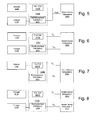
- Fig. 5 is a schematic block diagram of an exemplary mobile device power supply system.
- Fig. 6 is a schematic block diagram of an exemplary mobile device power supply system.
- Fig. 7 is a schematic block diagram of an exemplary mobile device power supply system.
- Fig. 8 is a schematic block diagram of an exemplary mobile device power supply system.
- Fig. 10 is a schematic block diagram of an exemplary mobile device power supply system.
- Fig. 12 is a schematic block diagram of an exemplary mobile device power supply system.
- Fig. 13 is a schematic block diagram of an exemplary mobile device power supply system.
- a method is here, and generally, conceived to be a sequence of steps or actions leading to a desired result and may be implemented as software. While it may prove convenient to discuss such software as if were embodied by a single program, most implementations will distribute the described functions among discrete (and some not so discrete) pieces of software. These pieces are often described using such terms of art as "programs.” “objects.” “functions.” “subroutines,” “libraries,” “.dlls.” “APIs.” and “procedures.” While one or more of these terms may find favor in the present description, there is no intention to limit the invention to the described configurations.
- an element number followed by a letter generally indicates multiple occurrences of similar, either in structure or function, elements.
- an italicized "n" (e.g. n) associated with an element number generally denotes either an unspecified one of such elements or a partial or complete group of such elements, the meaning of which is to be drawn from the context of such use.
- FIG.s 1 and 2 illustrate an exemplary mobile device 100 having a body 102 and a handle 101.
- the body 102 generally supports a variety of components, including: a battery 105; a LCD with touch screen 106; a keyboard 108 (including a scan button 109); a scan engine 110; a data/charging port 112 and a battery pack 120.
- the scan engine 110 may comprise, for example, an image engine or a laser engine.
- the data/charging port 112 may comprise an interface with pins or pads for the transmitting and receiving of data and receiving power for charging the battery.
- FIG. 3 is a simplified block diagram of an exemplary mobile device 1000 which may include a number of subsystems (collectively referred to as 2000) central processing unit (CPU) 1010 which receives data from and outputs data to other sub-systems for storage, transmission and additional processing.
- CPU 1010 may be implemented using any number of off the shelf solutions including: embedded processors; general purpose processors; custom solutions such as pre-configured field programmable gate arrays (FPGAs) and application specific integrated circuits (ASICs).
- FPGAs field programmable gate arrays
- ASICs application specific integrated circuits
- Communication to and from the CPU 1010 and the various subcomponents may be via one or more ports or busses, including a main system bus 1012; l 2 C busses 1013a and 1013b; a plurality of Universal Asynchronous Receivers/Transmitter (UART) ports 1014n, a Universal Serial Bus (USB) 1015n, and an RS-232 port 1016.
- UART Universal Asynchronous Receivers/Transmitter
- USB Universal Serial Bus
- the image signal generating system 1028 generally comprises a two dimensional solid state image sensor 1029 utilizing such technologies as CCD, CMOS, and CID, for capturing an image containing data, e.g. a bar code or signature.
- Two-dimensional solid state image sensors generally have a plurality of photo sensor picture elements ("pixels") which are formed in a pattern including a plurality of rows and a plurality of columns of pixels.
- the image signal generating system 1028 further includes an imaging optics (not shown) focusing an image onto an active surface of the image sensor 1029.
- Image sensor 1029 may be incorporated on an image sensor IC chip having disposed thereon image sensor control circuitry, image signal conditioning circuitry, and an analog-to-digital converter.
- FPGA 1022 manages the capture and transfer of image data into RAM 1017n. Decoding may be performed by the CPU 1010 or any suitable secondary processor. A variety of alternatives, including a dedicated laser barcode scanner 1035 may also be utilized.
- One use of the image signal generating system 1028 is for reading and interpreting bar codes such as bar code 1051 a on an item 1050.
- the CPU 1010 causes the appropriate control signals to be sent to the image sensor 1029.
- the image sensor 1029 outputs digital image data including (hopefully) an adequate representation of the bar code symbol 1050.
- the digital image data is streamed to the FPGA 1022 where it is collected and subsequently deposited in memory 1017n.
- a decoding program (not specifically illustrated) an attempt may be made to decode the bar code represented in the captured electronic image representation.
- the capture and decoding of image data may occur automatically in response to a trigger signal being generated, usually by activation of the scan button 1036 or a pre-selected key on keyboard 1034.
- the CPU 1010 may be configured, typically through execution of a program resident in memory 1017n, to continuously capture and decode bar code symbols represented therein as long as scan button 1036 is actuated. The cycle may be terminated upon successfully decoding the bar code symbol or by timing out after a number of unsuccessful attempts.
- the image signal generation system 1028 may also be configured for an image capture operation.
- control circuit 1010 captures an electronic image representation in response to the scan button 1036 being actuated without attempting to decode a decodable symbol represented therein.
- the captured electronic image representation may be one or more of (i) stored into a designated memory location of memory 1017n, (ii) transmitted to an external spaced apart device, or (iii) displayed on LCD 1020. This mode may be used to capture, for example an image of a signature or damage to a package.
- the image signal generation system 1028 may be operated in two distinct stages: aiming and final capture.
- aiming stage frames output by the image signal generation system 1028 are displayed on the LCD display 1020. These frames are not saved.
- final capture stage a frame (either the frame currently in the buffer or a next frame) is saved and typically displayed on the LCD 1020.
- the aiming stage is initiated by pressing a designated button (such as a scan button 1036) with the final capture stage being initiated by releasing the designated button.
- the mobile device 1000 may include a card reader unit 1040 for reading data from a card 1052.
- Card reader unit 1040 generally comprises a signal detection circuit 1042a and a data decode circuit 1042b.
- the signal detection circuit 1042a detects data, from for example a magnetic strip 1053 on a card 1052.
- the data decode circuit 1042b decodes the data.
- the decoded data may be transmitted to the CPU 1010 for further processing via the FPGA 1022.
- the card reader unit 1040 can be selected to be of a type that reads card information encoded in more than one data format, such as magnetic stripe data, smart card or Integrated circuit card (IC card) data, and RF transmitted data.
- An exemplary power circuit 1100 supplies power to the mobile device 1000.
- the power circuit 1100 generally comprises a series of power regulators 1102n that regulate the power supplied to the various components of the mobile device 1000.
- the power regulators 1102n each generally comprise step up or step down circuits which are in turn connected to each of the various components in the mobile device 1000 that require the particular voltage output by that power regulator 1102n.
- the power regulators receive current from a power bus 1103 which is, in turn, supplied by an exemplary power source 1104, a first power input 1106 or a connector 1108 that includes a second power input.
- the first power input 1106 may comprise a DC power jack, for example, a 2.5 mm coaxial DC power plug which receives 9.5 volts from a conventional AC/DC transformer.
- the connector 1108 may comprise any number of known connection technologies. Certain pins of the connector 1108 may be dedicated to receiving DC power while other pins are dedicated to one or more communication paths, such as RS-232 and USB. It may also prove advantageous to provide DC power out, for example from a power supply 1102a, so as to power tethered accessories, such as external magnetic stripe or RFID readers (not shown). It may prove further advantageous to add circuitry to insulate the first power input 1106 from the second power input on the connector 1108 and other components in the mobile device 1000 in the event that a user attempts to supply power to both power inputs.
- the power source 1104 may be charged by a charge circuit 1110 which receives power from either the first power input 1106 or the second power input on the connector 1108. Control may be provided to the CPU 1010 which may modify the charging behavior of the charge circuit 1110 based on information generated by the auxiliary processor 1024. In an exemplary embodiment, the auxiliary processor 1024 monitors parameters via an interface. A switch 1112 may control the power source based upon the presence of power from the first power input 1106 or the second power input on the connector 1108. Thus, when an external power supply is connected to either the power input 1106 or the second power input on the connector 1108, the power source is isolated from the power regulators 1102n and may be charged via the charge circuit 1110. Once power is removed from the power input 1106 and the connector 1108, the power source is connected to the power regulators 1102n.
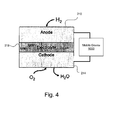
- An exemplary power source 1104 may be comprised of an energy storage system with a rapid or short charge cycle, such as a fuel cell which, as illustrated in Fig. 4 , is at least one open electrochemical cell comprised of an anode 210 and cathode 214 separated by an electrolyte 218 that converts a source fuel into an electrical current and water. It generates electricity inside a cell through reactions between a fuel and an oxidant, triggered in the presence of an electrolyte. The reactants flow into the cell, and the reaction products flow out of it, while the electrolyte remains within it.
- Fuel cells are thermodynamically open electrochemical cell systems that consume a reactant from an external source, which must be replenished. Many combinations of fuels and oxidants are possible.
- a hydrogen fuel cell uses hydrogen as its fuel and oxygen as its oxidant.
- Other fuels may include hydrocarbons and alcohols.
- Other oxidants may include chlorine and chlorine dioxide.
- power source 1104 may be comprised of a hybrid battery pack 1104 comprising a fuel cell 1410 and a thermodynamically closed electrochemical cell battery 1414, such as a NiMh, NiCd, Li Ion, or Li Polymer cell battery connected to generate a single output voltage Vout.
- a hybrid battery pack 1104 comprising a fuel cell 1410 and a thermodynamically closed electrochemical cell battery 1414, such as a NiMh, NiCd, Li Ion, or Li Polymer cell battery connected to generate a single output voltage Vout.
- Steady state conditions may be those conditions wherein a specified characteristic of a condition, such as a value, rate, periodicity, or amplitude, exhibits only negligible change over a predetermined period of time.
- a steady state condition may exist after all initial transients or fluctuating conditions have damped out, and all currents, voltages, or fields remain essentially constant, or oscillate uniformly.
- power source 1104 may be comprised of a hybrid battery pack 1104 comprising a fuel cell 1410 and a thermodynamically closed electrochemical cell battery 1414, such as a NiMh, NiCd, Li Ion, or Li Polymer cell battery wherein the fuel cell 1410 powers the mobile device during times of high current load requirements and the thermodynamically closed electrochemical cell battery powers the mobile device during lower current load requirements, such as steady state type conditions.
- a hybrid battery pack 1104 comprising a fuel cell 1410 and a thermodynamically closed electrochemical cell battery 1414, such as a NiMh, NiCd, Li Ion, or Li Polymer cell battery wherein the fuel cell 1410 powers the mobile device during times of high current load requirements and the thermodynamically closed electrochemical cell battery powers the mobile device during lower current load requirements, such as steady state type conditions.
- power source 1104 may be comprised of a hybrid battery pack 1104 comprising a fuel cell 1410 which charges a thermodynamically closed electrochemical cell battery 1414, such as a NiMh, NiCd, Li Ion, or Li Polymer cell battery.
- a thermodynamically closed electrochemical cell battery 1414 such as a NiMh, NiCd, Li Ion, or Li Polymer cell battery.
- power source may be comprised of a hybrid battery pack 1104 comprising a fuel cell and a thermodynamically closed electrochemical cell battery 1414, such as a NiMh, NiCd, Li Ion, or Li Polymer cell battery, wherein the fuel cell may be removed from the mobile device and placed into a charging station separate from the mobile device, at which time power for any onboard systems of the mobile device that need to continue in an "active" state (such as WiFi, GPS, etc) may be provided by the thermodynamically closed electrochemical cell battery.
- a hybrid battery pack 1104 comprising a fuel cell and a thermodynamically closed electrochemical cell battery 1414, such as a NiMh, NiCd, Li Ion, or Li Polymer cell battery
- an exemplary ultracapacitor may be described and illustrated as an electrolyte suspended between two nonreactive porous electrodes (or plates or collectors) with a voltage potential applied across the collectors.
- the applied potential on a positive electrode attracts negative ions in the electrolyte, while the potential on the negative electrode attracts the positive ions.
- a dielectric separator between the two electrodes prevents charge from moving between the two electrodes.
- the ultracapacitor relies on the microscopic charge separation at an electrochemical interface to store energy. Since the capacitance of these devices is proportional to the active electrode area, increasing the electrode surface area increase the capacitance, hence increasing the amount of energy that can be stored. High surface area is achieved by utilizing nanoporous material as the electrolyte, such as activated carbon or sintered metal powders. Use of nanoporous material results in an effective separation of charge despite the thin (on the order of nanometers) physical separation of the layers. The lack of need for a bulky layer of dielectric permits the packing of "plates" with much larger surface area into a given size, resulting in high capacitances in small packages.
- Ultracapacitors have a high energy density when compared to common capacitors, typically on the order of thousands of times greater than a high capacity electrolytic capacitor.
- a typical D-cell sized electrolytic capacitor will have a capacitance in the range of tens of millifarads.
- the same size electric double-layer capacitor would have a capacitance of several farads, an improvement of about two or three orders of magnitude in capacitance, but usually at a lower working voltage.
- power source 1104 may be comprised of a hybrid battery pack 1104 comprising an ultracapacitor 1420 and a thermodynamically closed electrochemical cell battery 1414, such as a NiMh, NiCd, Li Ion, or Li Polymer cell battery, wherein the ultracapacitor powers the mobile device during times of high current load requirements and the thermodynamically closed electrochemical cell battery provides power during lower current load requirements, such as steady state type conditions.
- a hybrid battery pack 1104 comprising an ultracapacitor 1420 and a thermodynamically closed electrochemical cell battery 1414, such as a NiMh, NiCd, Li Ion, or Li Polymer cell battery, wherein the ultracapacitor powers the mobile device during times of high current load requirements and the thermodynamically closed electrochemical cell battery provides power during lower current load requirements, such as steady state type conditions.
- power source 1104 may be comprised of a hybrid battery pack 1104 comprising an ultracapacitor 1420 and a thermodynamically closed electrochemical cell battery 1414, such as a NiMh, NiCd, Li Ion, or Li Polymer cell battery, which charges an ultracapacitor 1420.
- a hybrid battery pack 1104 comprising an ultracapacitor 1420 and a thermodynamically closed electrochemical cell battery 1414, such as a NiMh, NiCd, Li Ion, or Li Polymer cell battery, which charges an ultracapacitor 1420.
- the ultracapacitor may be internal to the body or housing of the mobile device.
- the ultracapacitor would charge through a connector provided on the mobile device.
Landscapes
- Engineering & Computer Science (AREA)
- Artificial Intelligence (AREA)
- Computer Vision & Pattern Recognition (AREA)
- Physics & Mathematics (AREA)
- General Physics & Mathematics (AREA)
- Theoretical Computer Science (AREA)
- Telephone Function (AREA)
- Charge And Discharge Circuits For Batteries Or The Like (AREA)
- Power Sources (AREA)
- Mobile Radio Communication Systems (AREA)
Applications Claiming Priority (1)
| Application Number | Priority Date | Filing Date | Title |
|---|---|---|---|
| US12/819,671 US8333323B2 (en) | 2010-06-21 | 2010-06-21 | Mobile device using short cycle power source |
Publications (3)
| Publication Number | Publication Date |
|---|---|
| EP2397965A2 true EP2397965A2 (de) | 2011-12-21 |
| EP2397965A3 EP2397965A3 (de) | 2012-02-01 |
| EP2397965B1 EP2397965B1 (de) | 2013-09-11 |
Family
ID=44546281
Family Applications (1)
| Application Number | Title | Priority Date | Filing Date |
|---|---|---|---|
| EP20110169203 Not-in-force EP2397965B1 (de) | 2010-06-21 | 2011-06-08 | Mobile Vorrichtung mit Stromquelle mit kurzem Zyklus |
Country Status (3)
| Country | Link |
|---|---|
| US (1) | US8333323B2 (de) |
| EP (1) | EP2397965B1 (de) |
| CN (1) | CN102426474B (de) |
Families Citing this family (19)
| Publication number | Priority date | Publication date | Assignee | Title |
|---|---|---|---|---|
| US7813047B2 (en) | 2006-12-15 | 2010-10-12 | Hand Held Products, Inc. | Apparatus and method comprising deformable lens element |
| US8027096B2 (en) | 2006-12-15 | 2011-09-27 | Hand Held Products, Inc. | Focus module and components with actuator polymer control |
| US8305691B2 (en) | 2009-04-29 | 2012-11-06 | Hand Held Products, Inc. | Fluid lens element for use in changing thermal operating environment |
| US9047531B2 (en) | 2010-05-21 | 2015-06-02 | Hand Held Products, Inc. | Interactive user interface for capturing a document in an image signal |
| US8600167B2 (en) | 2010-05-21 | 2013-12-03 | Hand Held Products, Inc. | System for capturing a document in an image signal |
| US8366002B2 (en) | 2010-05-26 | 2013-02-05 | Hand Held Products, Inc. | Solid elastic lens element and method of making same |
| US8718718B2 (en) * | 2012-03-20 | 2014-05-06 | Alan Siu Kit LEUNG | Power WiFi device |
| US10475024B1 (en) | 2012-10-15 | 2019-11-12 | Square, Inc. | Secure smart card transactions |
| US9760740B1 (en) | 2014-06-23 | 2017-09-12 | Square, Inc. | Terminal case with integrated dual reader stack |
| EP3167404B1 (de) | 2014-07-08 | 2020-11-04 | Aila Technologies, Inc. | Bildgebungs- und peripherieverbesserungen für mobile vorrichtungen |
| US9870491B1 (en) * | 2014-08-01 | 2018-01-16 | Square, Inc. | Multiple battery management |
| US10753982B2 (en) | 2014-12-09 | 2020-08-25 | Square, Inc. | Monitoring battery health of a battery used in a device |
| US10153650B2 (en) * | 2015-12-15 | 2018-12-11 | Intel Corporation | Energy harvesting system for IoT devices |
| US10325436B2 (en) | 2015-12-31 | 2019-06-18 | Hand Held Products, Inc. | Devices, systems, and methods for optical validation |
| DE102016203355A1 (de) | 2016-03-01 | 2017-09-07 | Kuka Roboter Gmbh | Elektrische Vorrichtung mit einem getakteten Netzteil und Verfahren zum Überprüfen des Netzteils der elektrischen Vorrichtung |
| US9864887B1 (en) * | 2016-07-07 | 2018-01-09 | Hand Held Products, Inc. | Energizing scanners |
| JP2018180754A (ja) * | 2017-04-07 | 2018-11-15 | 日立オムロンターミナルソリューションズ株式会社 | カード処理装置および自動取引機 |
| CN110718966B (zh) * | 2019-10-25 | 2020-12-25 | 云南电网有限责任公司信息中心 | 一种电力设备数据采集及管理方法 |
| CN110768369B (zh) * | 2019-11-29 | 2021-01-22 | 贵州梅岭电源有限公司 | 一种超大功率热电池稳压电源系统 |
Family Cites Families (8)
| Publication number | Priority date | Publication date | Assignee | Title |
|---|---|---|---|---|
| US6628107B1 (en) | 2001-10-31 | 2003-09-30 | Symbol Technologies, Inc. | Power management for a portable electronic device |
| JP2004297753A (ja) | 2003-02-07 | 2004-10-21 | Nec Tokin Corp | 電源回路、及び該電源回路を備えた通信機器 |
| US7932634B2 (en) * | 2003-03-05 | 2011-04-26 | The Gillette Company | Fuel cell hybrid power supply |
| FR2878087A1 (fr) * | 2004-11-15 | 2006-05-19 | France Telecom | Chargeur electrique autonome |
| US7551087B2 (en) * | 2005-08-19 | 2009-06-23 | Adasa, Inc. | Handheld and cartridge-fed applicator for commissioning wireless sensors |
| US7798408B2 (en) | 2006-07-10 | 2010-09-21 | Hand Held Products, Inc. | Apparatus and methods for controlling an imager |
| GB2445002A (en) | 2006-12-22 | 2008-06-25 | Nokia Corp | Power supply for a Portable device |
| CN101685963B (zh) * | 2008-09-22 | 2012-06-06 | 联想(北京)有限公司 | 一种供电方法、供电装置及供电系统 |
-
2010
- 2010-06-21 US US12/819,671 patent/US8333323B2/en active Active
-
2011
- 2011-06-08 EP EP20110169203 patent/EP2397965B1/de not_active Not-in-force
- 2011-06-20 CN CN201110209519.7A patent/CN102426474B/zh not_active Expired - Fee Related
Non-Patent Citations (1)
| Title |
|---|
| None |
Also Published As
| Publication number | Publication date |
|---|---|
| EP2397965B1 (de) | 2013-09-11 |
| US20110309145A1 (en) | 2011-12-22 |
| EP2397965A3 (de) | 2012-02-01 |
| CN102426474A (zh) | 2012-04-25 |
| CN102426474B (zh) | 2015-12-16 |
| US8333323B2 (en) | 2012-12-18 |
Similar Documents
| Publication | Publication Date | Title |
|---|---|---|
| US8333323B2 (en) | Mobile device using short cycle power source | |
| US9411386B2 (en) | Mobile device with tamper detection | |
| US7748632B2 (en) | Portable data terminal and battery therefor | |
| US7571857B2 (en) | Apparatus and methods for acquiring GPS data for use with portable data terminals | |
| US10049246B2 (en) | Mini-barcode reading module with flash memory management | |
| US8548420B2 (en) | Panic button for data collection device | |
| US9135483B2 (en) | Terminal having image data format conversion | |
| US8881983B2 (en) | Optical readers and methods employing polarization sensing of light from decodable indicia | |
| EP2360618B1 (de) | Datenerfassungsmodul und -system | |
| EP3018557A1 (de) | Strichcodeabtastsystem mit tragbarer vorrichtung mit eingebetteter kamera | |
| US7577516B2 (en) | Power management apparatus and methods for portable data terminals | |
| US20160204638A1 (en) | Charger with an energy storage element | |
| US20080181465A1 (en) | Apparatus and methods for identifying patients | |
| CN101799880B (zh) | 信息处理装置、信息处理方法和信息处理系统 | |
| US8098237B2 (en) | Stylus for data collection devices | |
| US8392260B2 (en) | Short-charge cordless scanner for retail terminals | |
| US10523038B2 (en) | System and method for wireless charging of a beacon and/or sensor device | |
| EP2466417B1 (de) | Batterieabschaltschema für ein tragbares Datenendgerät | |
| JP2013156755A (ja) | ハンディターミナル及びハンディターミナル用充電器並びにハンディターミナルの充電方法 | |
| US7798408B2 (en) | Apparatus and methods for controlling an imager | |
| CN219085436U (zh) | 一种支持双sensor扫描引擎的无线数据终端设备 | |
| RU214842U1 (ru) | Мобильный терминал товарной корзины | |
| CN218450554U (zh) | 一种防止换电池丢失数据的无线数据终端设备 | |
| CN106879077A (zh) | 简单的wi-fi连接系统和方法 | |
| GB2535845A (en) | Charger with energy storage element |
Legal Events
| Date | Code | Title | Description |
|---|---|---|---|
| 17P | Request for examination filed |
Effective date: 20110608 |
|
| AK | Designated contracting states |
Kind code of ref document: A2 Designated state(s): AL AT BE BG CH CY CZ DE DK EE ES FI FR GB GR HR HU IE IS IT LI LT LU LV MC MK MT NL NO PL PT RO RS SE SI SK SM TR |
|
| AX | Request for extension of the european patent |
Extension state: BA ME |
|
| PUAI | Public reference made under article 153(3) epc to a published international application that has entered the european phase |
Free format text: ORIGINAL CODE: 0009012 |
|
| PUAL | Search report despatched |
Free format text: ORIGINAL CODE: 0009013 |
|
| AK | Designated contracting states |
Kind code of ref document: A3 Designated state(s): AL AT BE BG CH CY CZ DE DK EE ES FI FR GB GR HR HU IE IS IT LI LT LU LV MC MK MT NL NO PL PT RO RS SE SI SK SM TR |
|
| AX | Request for extension of the european patent |
Extension state: BA ME |
|
| RIC1 | Information provided on ipc code assigned before grant |
Ipc: G06K 7/00 20060101AFI20111223BHEP |
|
| 17Q | First examination report despatched |
Effective date: 20120323 |
|
| GRAP | Despatch of communication of intention to grant a patent |
Free format text: ORIGINAL CODE: EPIDOSNIGR1 |
|
| INTG | Intention to grant announced |
Effective date: 20130419 |
|
| RIN1 | Information on inventor provided before grant (corrected) |
Inventor name: RICHARDSON, NEIL Inventor name: HINSON, DOUGLAS Inventor name: SAUERWEIN, JR., JAMES TIMOTHY Inventor name: WANG, YNJIUN PAUL |
|
| GRAS | Grant fee paid |
Free format text: ORIGINAL CODE: EPIDOSNIGR3 |
|
| GRAA | (expected) grant |
Free format text: ORIGINAL CODE: 0009210 |
|
| AK | Designated contracting states |
Kind code of ref document: B1 Designated state(s): AL AT BE BG CH CY CZ DE DK EE ES FI FR GB GR HR HU IE IS IT LI LT LU LV MC MK MT NL NO PL PT RO RS SE SI SK SM TR |
|
| REG | Reference to a national code |
Ref country code: GB Ref legal event code: FG4D |
|
| REG | Reference to a national code |
Ref country code: CH Ref legal event code: EP |
|
| REG | Reference to a national code |
Ref country code: AT Ref legal event code: REF Ref document number: 631988 Country of ref document: AT Kind code of ref document: T Effective date: 20130915 |
|
| REG | Reference to a national code |
Ref country code: IE Ref legal event code: FG4D |
|
| REG | Reference to a national code |
Ref country code: DE Ref legal event code: R096 Ref document number: 602011002974 Country of ref document: DE Effective date: 20131107 |
|
| PG25 | Lapsed in a contracting state [announced via postgrant information from national office to epo] |
Ref country code: CY Free format text: LAPSE BECAUSE OF FAILURE TO SUBMIT A TRANSLATION OF THE DESCRIPTION OR TO PAY THE FEE WITHIN THE PRESCRIBED TIME-LIMIT Effective date: 20130731 Ref country code: LT Free format text: LAPSE BECAUSE OF FAILURE TO SUBMIT A TRANSLATION OF THE DESCRIPTION OR TO PAY THE FEE WITHIN THE PRESCRIBED TIME-LIMIT Effective date: 20130911 Ref country code: NO Free format text: LAPSE BECAUSE OF FAILURE TO SUBMIT A TRANSLATION OF THE DESCRIPTION OR TO PAY THE FEE WITHIN THE PRESCRIBED TIME-LIMIT Effective date: 20131211 Ref country code: SE Free format text: LAPSE BECAUSE OF FAILURE TO SUBMIT A TRANSLATION OF THE DESCRIPTION OR TO PAY THE FEE WITHIN THE PRESCRIBED TIME-LIMIT Effective date: 20130911 Ref country code: HR Free format text: LAPSE BECAUSE OF FAILURE TO SUBMIT A TRANSLATION OF THE DESCRIPTION OR TO PAY THE FEE WITHIN THE PRESCRIBED TIME-LIMIT Effective date: 20130911 |
|
| REG | Reference to a national code |
Ref country code: NL Ref legal event code: VDEP Effective date: 20130911 |
|
| REG | Reference to a national code |
Ref country code: AT Ref legal event code: MK05 Ref document number: 631988 Country of ref document: AT Kind code of ref document: T Effective date: 20130911 |
|
| REG | Reference to a national code |
Ref country code: LT Ref legal event code: MG4D |
|
| PG25 | Lapsed in a contracting state [announced via postgrant information from national office to epo] |
Ref country code: GR Free format text: LAPSE BECAUSE OF FAILURE TO SUBMIT A TRANSLATION OF THE DESCRIPTION OR TO PAY THE FEE WITHIN THE PRESCRIBED TIME-LIMIT Effective date: 20131212 Ref country code: SI Free format text: LAPSE BECAUSE OF FAILURE TO SUBMIT A TRANSLATION OF THE DESCRIPTION OR TO PAY THE FEE WITHIN THE PRESCRIBED TIME-LIMIT Effective date: 20130911 Ref country code: LV Free format text: LAPSE BECAUSE OF FAILURE TO SUBMIT A TRANSLATION OF THE DESCRIPTION OR TO PAY THE FEE WITHIN THE PRESCRIBED TIME-LIMIT Effective date: 20130911 Ref country code: FI Free format text: LAPSE BECAUSE OF FAILURE TO SUBMIT A TRANSLATION OF THE DESCRIPTION OR TO PAY THE FEE WITHIN THE PRESCRIBED TIME-LIMIT Effective date: 20130911 |
|
| PG25 | Lapsed in a contracting state [announced via postgrant information from national office to epo] |
Ref country code: CY Free format text: LAPSE BECAUSE OF FAILURE TO SUBMIT A TRANSLATION OF THE DESCRIPTION OR TO PAY THE FEE WITHIN THE PRESCRIBED TIME-LIMIT Effective date: 20130911 Ref country code: BE Free format text: LAPSE BECAUSE OF FAILURE TO SUBMIT A TRANSLATION OF THE DESCRIPTION OR TO PAY THE FEE WITHIN THE PRESCRIBED TIME-LIMIT Effective date: 20130911 |
|
| PG25 | Lapsed in a contracting state [announced via postgrant information from national office to epo] |
Ref country code: RO Free format text: LAPSE BECAUSE OF FAILURE TO SUBMIT A TRANSLATION OF THE DESCRIPTION OR TO PAY THE FEE WITHIN THE PRESCRIBED TIME-LIMIT Effective date: 20130911 Ref country code: EE Free format text: LAPSE BECAUSE OF FAILURE TO SUBMIT A TRANSLATION OF THE DESCRIPTION OR TO PAY THE FEE WITHIN THE PRESCRIBED TIME-LIMIT Effective date: 20130911 Ref country code: IS Free format text: LAPSE BECAUSE OF FAILURE TO SUBMIT A TRANSLATION OF THE DESCRIPTION OR TO PAY THE FEE WITHIN THE PRESCRIBED TIME-LIMIT Effective date: 20140111 Ref country code: SK Free format text: LAPSE BECAUSE OF FAILURE TO SUBMIT A TRANSLATION OF THE DESCRIPTION OR TO PAY THE FEE WITHIN THE PRESCRIBED TIME-LIMIT Effective date: 20130911 Ref country code: NL Free format text: LAPSE BECAUSE OF FAILURE TO SUBMIT A TRANSLATION OF THE DESCRIPTION OR TO PAY THE FEE WITHIN THE PRESCRIBED TIME-LIMIT Effective date: 20130911 Ref country code: CZ Free format text: LAPSE BECAUSE OF FAILURE TO SUBMIT A TRANSLATION OF THE DESCRIPTION OR TO PAY THE FEE WITHIN THE PRESCRIBED TIME-LIMIT Effective date: 20130911 |
|
| PG25 | Lapsed in a contracting state [announced via postgrant information from national office to epo] |
Ref country code: PL Free format text: LAPSE BECAUSE OF FAILURE TO SUBMIT A TRANSLATION OF THE DESCRIPTION OR TO PAY THE FEE WITHIN THE PRESCRIBED TIME-LIMIT Effective date: 20130911 Ref country code: ES Free format text: LAPSE BECAUSE OF FAILURE TO SUBMIT A TRANSLATION OF THE DESCRIPTION OR TO PAY THE FEE WITHIN THE PRESCRIBED TIME-LIMIT Effective date: 20130911 Ref country code: AT Free format text: LAPSE BECAUSE OF FAILURE TO SUBMIT A TRANSLATION OF THE DESCRIPTION OR TO PAY THE FEE WITHIN THE PRESCRIBED TIME-LIMIT Effective date: 20130911 |
|
| REG | Reference to a national code |
Ref country code: DE Ref legal event code: R097 Ref document number: 602011002974 Country of ref document: DE |
|
| PG25 | Lapsed in a contracting state [announced via postgrant information from national office to epo] |
Ref country code: PT Free format text: LAPSE BECAUSE OF FAILURE TO SUBMIT A TRANSLATION OF THE DESCRIPTION OR TO PAY THE FEE WITHIN THE PRESCRIBED TIME-LIMIT Effective date: 20140113 |
|
| PLBE | No opposition filed within time limit |
Free format text: ORIGINAL CODE: 0009261 |
|
| STAA | Information on the status of an ep patent application or granted ep patent |
Free format text: STATUS: NO OPPOSITION FILED WITHIN TIME LIMIT |
|
| 26N | No opposition filed |
Effective date: 20140612 |
|
| PG25 | Lapsed in a contracting state [announced via postgrant information from national office to epo] |
Ref country code: IT Free format text: LAPSE BECAUSE OF FAILURE TO SUBMIT A TRANSLATION OF THE DESCRIPTION OR TO PAY THE FEE WITHIN THE PRESCRIBED TIME-LIMIT Effective date: 20130911 |
|
| REG | Reference to a national code |
Ref country code: DE Ref legal event code: R097 Ref document number: 602011002974 Country of ref document: DE Effective date: 20140612 |
|
| PG25 | Lapsed in a contracting state [announced via postgrant information from national office to epo] |
Ref country code: DK Free format text: LAPSE BECAUSE OF FAILURE TO SUBMIT A TRANSLATION OF THE DESCRIPTION OR TO PAY THE FEE WITHIN THE PRESCRIBED TIME-LIMIT Effective date: 20130911 |
|
| PG25 | Lapsed in a contracting state [announced via postgrant information from national office to epo] |
Ref country code: LU Free format text: LAPSE BECAUSE OF FAILURE TO SUBMIT A TRANSLATION OF THE DESCRIPTION OR TO PAY THE FEE WITHIN THE PRESCRIBED TIME-LIMIT Effective date: 20140608 Ref country code: MC Free format text: LAPSE BECAUSE OF FAILURE TO SUBMIT A TRANSLATION OF THE DESCRIPTION OR TO PAY THE FEE WITHIN THE PRESCRIBED TIME-LIMIT Effective date: 20130911 |
|
| REG | Reference to a national code |
Ref country code: CH Ref legal event code: PL |
|
| REG | Reference to a national code |
Ref country code: IE Ref legal event code: MM4A |
|
| PG25 | Lapsed in a contracting state [announced via postgrant information from national office to epo] |
Ref country code: LI Free format text: LAPSE BECAUSE OF NON-PAYMENT OF DUE FEES Effective date: 20140630 Ref country code: IE Free format text: LAPSE BECAUSE OF NON-PAYMENT OF DUE FEES Effective date: 20140608 Ref country code: CH Free format text: LAPSE BECAUSE OF NON-PAYMENT OF DUE FEES Effective date: 20140630 |
|
| PG25 | Lapsed in a contracting state [announced via postgrant information from national office to epo] |
Ref country code: MT Free format text: LAPSE BECAUSE OF FAILURE TO SUBMIT A TRANSLATION OF THE DESCRIPTION OR TO PAY THE FEE WITHIN THE PRESCRIBED TIME-LIMIT Effective date: 20130911 |
|
| PG25 | Lapsed in a contracting state [announced via postgrant information from national office to epo] |
Ref country code: SM Free format text: LAPSE BECAUSE OF FAILURE TO SUBMIT A TRANSLATION OF THE DESCRIPTION OR TO PAY THE FEE WITHIN THE PRESCRIBED TIME-LIMIT Effective date: 20130911 |
|
| REG | Reference to a national code |
Ref country code: FR Ref legal event code: PLFP Year of fee payment: 6 |
|
| PG25 | Lapsed in a contracting state [announced via postgrant information from national office to epo] |
Ref country code: BG Free format text: LAPSE BECAUSE OF FAILURE TO SUBMIT A TRANSLATION OF THE DESCRIPTION OR TO PAY THE FEE WITHIN THE PRESCRIBED TIME-LIMIT Effective date: 20130911 Ref country code: RS Free format text: LAPSE BECAUSE OF NON-PAYMENT OF DUE FEES Effective date: 20130911 |
|
| PG25 | Lapsed in a contracting state [announced via postgrant information from national office to epo] |
Ref country code: HU Free format text: LAPSE BECAUSE OF FAILURE TO SUBMIT A TRANSLATION OF THE DESCRIPTION OR TO PAY THE FEE WITHIN THE PRESCRIBED TIME-LIMIT; INVALID AB INITIO Effective date: 20110608 Ref country code: TR Free format text: LAPSE BECAUSE OF FAILURE TO SUBMIT A TRANSLATION OF THE DESCRIPTION OR TO PAY THE FEE WITHIN THE PRESCRIBED TIME-LIMIT Effective date: 20130911 |
|
| REG | Reference to a national code |
Ref country code: FR Ref legal event code: PLFP Year of fee payment: 7 |
|
| REG | Reference to a national code |
Ref country code: FR Ref legal event code: PLFP Year of fee payment: 8 |
|
| PG25 | Lapsed in a contracting state [announced via postgrant information from national office to epo] |
Ref country code: MK Free format text: LAPSE BECAUSE OF FAILURE TO SUBMIT A TRANSLATION OF THE DESCRIPTION OR TO PAY THE FEE WITHIN THE PRESCRIBED TIME-LIMIT Effective date: 20130911 |
|
| PG25 | Lapsed in a contracting state [announced via postgrant information from national office to epo] |
Ref country code: AL Free format text: LAPSE BECAUSE OF FAILURE TO SUBMIT A TRANSLATION OF THE DESCRIPTION OR TO PAY THE FEE WITHIN THE PRESCRIBED TIME-LIMIT Effective date: 20130911 |
|
| PGFP | Annual fee paid to national office [announced via postgrant information from national office to epo] |
Ref country code: DE Payment date: 20210628 Year of fee payment: 11 |
|
| REG | Reference to a national code |
Ref country code: DE Ref legal event code: R119 Ref document number: 602011002974 Country of ref document: DE |
|
| PG25 | Lapsed in a contracting state [announced via postgrant information from national office to epo] |
Ref country code: DE Free format text: LAPSE BECAUSE OF NON-PAYMENT OF DUE FEES Effective date: 20230103 |
|
| PGFP | Annual fee paid to national office [announced via postgrant information from national office to epo] |
Ref country code: FR Payment date: 20230622 Year of fee payment: 13 |
|
| PGFP | Annual fee paid to national office [announced via postgrant information from national office to epo] |
Ref country code: GB Payment date: 20230620 Year of fee payment: 13 |
|
| GBPC | Gb: european patent ceased through non-payment of renewal fee |
Effective date: 20240608 |
|
| PG25 | Lapsed in a contracting state [announced via postgrant information from national office to epo] |
Ref country code: FR Free format text: LAPSE BECAUSE OF NON-PAYMENT OF DUE FEES Effective date: 20240630 |
|
| PG25 | Lapsed in a contracting state [announced via postgrant information from national office to epo] |
Ref country code: GB Free format text: LAPSE BECAUSE OF NON-PAYMENT OF DUE FEES Effective date: 20240608 |