EP2397805A2 - Device for re-cooling of heat transfer media and coolants used in cooling technology and liquid coolers and cold recovery in ventilation technology - Google Patents
Device for re-cooling of heat transfer media and coolants used in cooling technology and liquid coolers and cold recovery in ventilation technology Download PDFInfo
- Publication number
- EP2397805A2 EP2397805A2 EP11004985A EP11004985A EP2397805A2 EP 2397805 A2 EP2397805 A2 EP 2397805A2 EP 11004985 A EP11004985 A EP 11004985A EP 11004985 A EP11004985 A EP 11004985A EP 2397805 A2 EP2397805 A2 EP 2397805A2
- Authority
- EP
- European Patent Office
- Prior art keywords
- heat exchanger
- heat
- flow
- cooling
- air
- Prior art date
- Legal status (The legal status is an assumption and is not a legal conclusion. Google has not performed a legal analysis and makes no representation as to the accuracy of the status listed.)
- Granted
Links
Images


Classifications
-
- F—MECHANICAL ENGINEERING; LIGHTING; HEATING; WEAPONS; BLASTING
- F28—HEAT EXCHANGE IN GENERAL
- F28D—HEAT-EXCHANGE APPARATUS, NOT PROVIDED FOR IN ANOTHER SUBCLASS, IN WHICH THE HEAT-EXCHANGE MEDIA DO NOT COME INTO DIRECT CONTACT
- F28D5/00—Heat-exchange apparatus having stationary conduit assemblies for one heat-exchange medium only, the media being in contact with different sides of the conduit wall, using the cooling effect of natural or forced evaporation
- F28D5/02—Heat-exchange apparatus having stationary conduit assemblies for one heat-exchange medium only, the media being in contact with different sides of the conduit wall, using the cooling effect of natural or forced evaporation in which the evaporating medium flows in a continuous film or trickles freely over the conduits
-
- F—MECHANICAL ENGINEERING; LIGHTING; HEATING; WEAPONS; BLASTING
- F28—HEAT EXCHANGE IN GENERAL
- F28C—HEAT-EXCHANGE APPARATUS, NOT PROVIDED FOR IN ANOTHER SUBCLASS, IN WHICH THE HEAT-EXCHANGE MEDIA COME INTO DIRECT CONTACT WITHOUT CHEMICAL INTERACTION
- F28C3/00—Other direct-contact heat-exchange apparatus
- F28C3/06—Other direct-contact heat-exchange apparatus the heat-exchange media being a liquid and a gas or vapour
- F28C3/08—Other direct-contact heat-exchange apparatus the heat-exchange media being a liquid and a gas or vapour with change of state, e.g. absorption, evaporation, condensation
Definitions
- the invention relates to a method for reducing the air volume flow in the recooling of heat transfer fluids and working fluids from refrigeration and liquid cooling and cooling recovery in ventilation technology from an air stream according to claim 1 and a device with a plurality of air streams, which are combined to form an air stream according to claim 2.
- DE 202 21 407 U1 (also DE 101 40 279 A1 ) describes a device for the recooling of coolants or recooling media or for cooling.
- the known recooling devices such as, for example, a cooling tower, hybrid coolers or dry coolers, are just as single-stage as a device that is designed in accordance with DE 202 21 407 U1 is constructed.
- the said recooling devices require a large airflow. For this reason, in the device according to DE 202 21 407 U1 the air flow is supersaturated with aerosols, which then change the physical state in the heat exchanger and evaporate under heat extraction, which can lead to a reduction of the air volume flow.
- the water absorption of the air is limited by its saturation state.
- the surface of the heat exchanger can not be wetted with water.
- it is not usable for the evaporation of water.
- a division or an adjustment of the recooling of the individual heat exchanger by admixture of at least one air flow is not possible.
- the object of the invention is to cool the air flow as far as possible by evaporative cooling before entering the first heat exchanger and cool the air again by evaporative cooling before entering the at least one other heat exchanger and the heat exchanger surface also during the further course of the re-cooling of heat transfer and working fluids from refrigeration by moistening the heat exchanger surface for the energy extraction to use.
- the object is achieved in a method according to the features of claim 1 and in a device according to the features of claim 2.
- the recooling of heat transfer fluids and agents with a multi-stage process of humidification and wetting the heat exchanger surface with water by the air is cooled before entering the first heat exchanger by evaporative cooling, then the air is reheated by at least one other heat exchanger and then removes the heat exchanger surface by wetting with water also the heat carrier or the working fluid further energy. It is particularly advantageous if the air from the first heat exchanger is heated so far that the air temperature after the first heat exchanger is higher than the air intake temperature of the first shipsbefeuchtungs thanks.
- the heat transfer medium enters the recooling device when the last heat exchanger in the direction of air flow a, then flows through each further series-connected heat exchanger and leaves the recooling device at the air inlet of the first heat exchanger.
- the invention is designed in a preferred construction by a series of heat exchangers and humidifiers in an air flow which is passed through a channel. To increase performance and control the energy output of individual heat exchangers, one or more air flow rates can be mixed in a preferred manner.
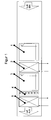
- FIG. 1 the preferred arrangement with two humidifiers 1 and 3, two heat exchangers 2 and 5 and a wetting device 4 is shown.
- FIG. 2 the preferred arrangement is shown with two humidifiers 1 and 3, two heat exchangers 2 and 5, a wetting device 4 and a connecting pipe 6 between the heat exchangers 2 and 5 in a circuit according to the countercurrent principle.
- FIG. 3 the preferred arrangement with two humidifiers 1 and 3, two heat exchangers 2 and 5 two wetting devices 4 and 9 is shown.
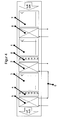
- FIG. 4 the preferred arrangement is shown with three humidifiers 1, 3 and 7, three heat exchangers 2, 5 and 8, two wetting devices 4 and 9 and a connecting pipe 6 between the heat exchangers 2 and 5 in a countercurrent circuit.
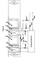
- FIG. 5 the preferred arrangement is shown with two humidifiers 1 and 3, two heat exchangers 2 and 5, two wetting devices 4 and 9 and a connecting pipe 6 between the heat exchangers 2 and 5 in a countercurrent circuit.
- This arrangement is designed for the operation of a liquid chiller with free cooling.
- the heat transfer medium flows through the heat exchanger 5, the pipeline 6, a valve 13, the heat exchanger 2 and a valve 12 to dissipate the condensation energy at warm air intake temperatures.
- a valve 10, a valve 11 and a valve 15 are closed here.
- the heat transfer medium to be cooled flows through a valve 14 is cooled by the liquid cooler and exits via a pipe 16 again.
- the fluid 2 is pre-cooled with the heat exchanger 2, the so-called free cooling takes place.
- the valves 14, 13 and 12 are closed and valves 11 and 15 are opened.
- the condensation energy is removed via the heat exchanger 5 by the valve 10 is opened.
- FIG. 8 For example, the preferred arrangement with two humidifiers 1 and 3, two heat exchangers 2 and 5, two humidifiers 4 and 9 and the piping 6 connecting the devices between the heat exchangers 2 and 5 are shown in parallel operation in a circuit.
- This arrangement is designed for the operation of a liquid chiller for high energy output to the air flow.
- the air By means of the heat exchanger 2, the air is heated, so that they can absorb more water after the heat exchanger 2 by means of the humidifier 3 again.
- the heat transfer in the following stage is, as before, improved by the wetting device 1 on the heat exchanger 2 in turn by the wetting device 3 on the heat exchanger 5.
- FIG. 9 a closed cooling tower 18 is shown, which has a cooling water device 19, an air supply 20, which generates a cooling air flow K, and a standard heat exchanger 21.
- the cooling water device 19 is provided as standard with a fresh water supply, an overflow and a discharge device.
- the standard heat exchanger 20 is preferably sprinkled by means of a sprinkler 22 with supplied or separated from the cooling air flow K water and thus recovers the energy from the heat transfer or working fluid from the refrigeration for the cooling tower 18 to be cooled plant 24.
- the heat carrier is in a closed heat transfer circuit 23 and is provided with a corresponding pump and control 25.
- an additional heat exchanger 2 is arranged above the sprinkler 22 (also in FIG FIG. 4 shown as heat exchanger 2).
- a moistening device 3 and, according to the invention, a further heat exchanger 5 (also in FIG FIG. 4 shown as heat exchanger 5).
- the heat exchanger 2 is connected by means of a pipe 26 and a three-way valve 28 to the heat transfer circuit 23 of the cooling tower 18.
- the heat exchanger 5 is connected by means of a pipe 27 and a three-way valve 29 to the heat transfer circuit 23 of the cooling tower 18.
- the moistening device 3 is connected by means of a pipe 30 to a water outlet of the cooling water device 19 and is thus supplied with existing already in the system moistening water.
- the cooling tower 18 can be better utilized. Either higher power can be guaranteed. Furthermore, the cooling tower can be made smaller. But above all, the power consumption of the air supply 20 can be significantly reduced, since by means of the additional heat exchanger 2, 5 in the leadership of the cooling air flow significantly improved cooling of the heat carrier succeeds.
Abstract
Description
Die Erfindung betrifft ein Verfahren zur Verringerung des Luftvolumenstromes bei der Rückkühlung von Wärmeträgern und Arbeitsstoffen aus der Kältetechnik und Flüssigkeitskühlern sowie Kälterückgewinnung in der Lüftungstechnik aus einem Luftstrom nach Anspruch 1 und eine Vorrichtung mit mehreren Luftströmen, die zu einem Luftstrom zusammengeführt werden nach Anspruch 2.The invention relates to a method for reducing the air volume flow in the recooling of heat transfer fluids and working fluids from refrigeration and liquid cooling and cooling recovery in ventilation technology from an air stream according to
Die Rückkühlung von Wärmeträgern und Arbeitsstoffen aus der Kältetechnik vor dem erneuten Einsatz für den Wärmetransport findet in der Regel über so genannte Trockenkühler und Kühltürme statt.The recooling of heat transfer fluids and working fluids from refrigeration before reuse for heat transport usually takes place via so-called dry coolers and cooling towers.
In diesem Zusammenhang ist in
Aus dem beschriebenen Stand der Technik ist die Wasseraufnahme der Luft begrenzt durch deren Sättigungszustand. Bei der Vorrichtung nach
Aufgabe der Erfindung ist es den Luftvolumenstrom möglichst weit durch Verdunstungskälte vor Eintritt in den ersten Wärmeaustauscher abzukühlen und während des weiteren Verlaufs der Rückkühlung von Wärmeträgern und Arbeitsstoffen aus der Kältetechnik die Luft erneut durch Verdunstungskälte vor Eintritt in den mindestens einen weiteren Wärmeaustauscher abzukühlen und die Wärmeaustauscherfläche ebenfalls durch befeuchten der Wärmeaustauscheroberfläche für den Energieentzug zu nutzen.The object of the invention is to cool the air flow as far as possible by evaporative cooling before entering the first heat exchanger and cool the air again by evaporative cooling before entering the at least one other heat exchanger and the heat exchanger surface also during the further course of the re-cooling of heat transfer and working fluids from refrigeration by moistening the heat exchanger surface for the energy extraction to use.
Die Lösung der Aufgabe gestaltet sich in einem Verfahren nach den Merkmalen von Anspruch 1 und in einer Vorrichtung nach den Merkmalen von Anspruch 2.The object is achieved in a method according to the features of
Dabei wird zur Rückkühlung von Wärmeträgern und Arbeitsstoffen mit einem mehrstufigen Verfahren der Luftbefeuchtung und Benetzung der Wärmeaustauscherfläche mit Wasser, indem die Luft vor Eintritt in den ersten Wärmeaustauscher durch Verdunstungskühlung abgekühlt wird, anschließend die Luft durch mindestens einen weiteren Wärmeaustauscher erneut erwärmt und danach entzieht die Wärmeaustauscheroberfläche durch Benetzung mit Wasser ebenfalls dem Wärmeträger oder dem Arbeitsstoff weitere Energie. Dabei ist es besonders vorteilhaft, wenn die Luft vom ersten Wärmeaustauscher soweit erwärmt wird, dass die Lufttemperatur nach dem ersten Wärmeaustauscher höher ist als die Luftansaugtemperatur der ersten Luftbefeuchtungseinrichtung.In this case, the recooling of heat transfer fluids and agents with a multi-stage process of humidification and wetting the heat exchanger surface with water by the air is cooled before entering the first heat exchanger by evaporative cooling, then the air is reheated by at least one other heat exchanger and then removes the heat exchanger surface by wetting with water also the heat carrier or the working fluid further energy. It is particularly advantageous if the air from the first heat exchanger is heated so far that the air temperature after the first heat exchanger is higher than the air intake temperature of the first Luftbefeuchtungseinrichtung.
Eine vorteilhafte Weiterbildung ergibt sich nach Anspruch 2 durch Beimischung von mindestens einem weiteren Luftvolumenstrom nach dem ersten beziehungsweise weiteren Wärmeaustauschern.An advantageous development results according to
Eine weitere vorteilhafte Weiterbildung ergibt sich nach Anspruch 3 durch Schaltung des Wärmeträgerstromes in Reihe nach dem Gegenstromprinzip. Der Wärmeträger tritt dabei in die Rückkühleinrichtung beim in Luftrichtung letzten Wärmeaustauscher ein, durchströmt dann jeden weiteren in Reihe geschalteten Wärmeaustauscher und verlässt die Rückkühleinrichtung beim Lufteintritt des ersten Wärmeaustauschers. Die Erfindung gestaltet sich in bevorzugter Bauweise durch eine Anreihung von Wärmeaustauschern und Befeuchtungseinrichtungen in einem Luftvolumenstrom der durch einen Kanal geführt wird. Zur Leistungssteigerung und Regelung der Energieabgabe einzelner Wärmeaustauscher können in bevorzugter Weise ein oder mehrere Luftvolumenströme beigemischt werden können.A further advantageous development results according to
Die Ausgestaltung des Verfahrens kann gemäß den jeweils vorliegenden Erfordernissen nachfolgend angepasst werden:
- 1. In Luftrichtung angeordnet einen Luftbefeuchter für die Verdunstungskühlung, anschließend ein Wärmeaustauscher, ein Luftbefeuchter für die Verdunstungskühlung die und eine Vorrichtung zur Benetzung des nachfolgenden Wärmeaustauschers mit Wasser.
- 2. In Luftrichtung angeordnet einen Luftbefeuchter für die Verdunstungskühlung, eine Vorrichtung zur Benetzung des nachfolgenden Wärmeaustauschers mit Wasser, anschließend ein Wärmeaustauscher, ein Luftbefeuchter für die Verdunstungskühlung die und eine Vorrichtung zur Benetzung des nachfolgenden Wärmeaustauschers mit Wasser.
- 3. Eine Anordnung in Luftrichtung von mindestens drei Luftbefeuchtungseinrichtungen und mindestens drei Wärmeaustauschern sowie mindestens eine Vorrichtung zur Benetzung eines nachfolgenden Wärmeaustauschers mit Wasser.
- 4. Eine Anordnung in Luftrichtung von mindestens zwei Luftbefeuchtungseinrichtungen und mindestens zwei Wärmeaustauschern sowie mindestens einer Vorrichtung zur Benetzung eines nachfolgenden Wärmeaustauschers mit Wasser sowie mindestens eine Vorrichtung zur Beimischung eines Luftvolumenstroms nach dem ersten Wärmeaustauscher zur Regelung der Leistung des nachfolgenden Wärmeaustauschers.
- 1. In the air direction arranged a humidifier for the evaporative cooling, then a heat exchanger, a humidifier for evaporative cooling and a device for wetting the subsequent heat exchanger with water.
- 2. In the air direction arranged a humidifier for evaporative cooling, a device for wetting the subsequent heat exchanger with water, then a heat exchanger, a humidifier for evaporative cooling and a device for wetting the subsequent heat exchanger with water.
- 3. An arrangement in the direction of air of at least three humidifiers and at least three heat exchangers and at least one device for wetting a subsequent heat exchanger with water.
- 4. An arrangement in the direction of air flow of at least two humidifiers and at least two heat exchangers and at least one device for wetting a subsequent heat exchanger with water and at least one device for admixing an air flow after the first heat exchanger to control the performance of the subsequent heat exchanger.
Die mit der Erfindung erzielbaren Vorteile bestehen unter anderem in den im Folgenden beschriebenen vorteilhaften Wirkungen:
- a) Der Luftvolumenstrom wird vermindert
- b) Die Leistungsaufnahme der Ventilatoren zur Förderung der Luft wird vermindert
- c) Es können verschiedene Wärmeträger in einer Vorrichtung gekühlt werden, so kann zum Beispiel der erste Wärmeaustauscher für die freie Kühlung des Wärmeträgers eines Flüssigkeitskühlers genutzt werden und der zweite Wärmeaustauscher um die Kondensationsenergie der Verdichter abzuführen.
- d) Die Temperaturspreizung des Wärmeträgers kann bei der Gegenstromanordnung größer ausgelegt werden, damit verringern sich die Volumenströme des Wärmeträgers und die Leistungsaufnahme der Umwälzpumpen wird verringert.
- a) The air volume flow is reduced
- b) The power consumption of fans to move the air is reduced
- c) Various heat transfer media can be cooled in one device, for example the first heat exchanger can be used for the free cooling of the heat carrier of a liquid cooler and the second heat exchanger can be removed by the condensation energy of the compressors.
- d) The temperature spread of the heat carrier can be designed to be larger in the counterflow arrangement, thus reducing the volume flows of the heat carrier and the power consumption of the circulation pump is reduced.
Die Erfindung wird im Folgenden anhand von zeichnerischen Darstellungen näher erläutert.The invention is explained in more detail below with reference to drawings.
Dabei zeigen
Figur 1- eine erfindungsgemäße Anordnung mit zwei Befeuchtern, zwei Wärmeaustauschern und einer Benetzungsvorrichtung,
Figur 2- eine erfindungsgemäße Anordnung nach
Figur 1 Figur 3- eine erfindungsgemäße Anordnung nach
Figur 1
Figur 4- eine erfindungsgemäße Anordnung nach
Figur 2 Figur 5- eine erfindungsgemäße Anordnung nach
Figur 3Verbindung 6 zwischen den Wärmeaustauschern im Gegenstromprinzip mit einem Flüssigkeitskühler mit freier Kühlung, Figur 6- eine erfindungsgemäße Anordnung zur Beimischung eines Luftvolumenstromes,
Figur 7- einen beispielhaften Verlauf des Luftzustands in einer Vorrichtung nach
Figur 1 Figur 8- eine Ausführungsform der Erfindung mit paralleler Anordnung der Wärmetauscher und
Figur 9- eine Ausführungsform der Erfindung mit einem geschlossenen Kühlturm.
- FIG. 1
- an inventive arrangement with two humidifiers, two heat exchangers and a wetting device,
- FIG. 2
- an inventive arrangement according to
FIG. 1 with a connection between the heat exchangers in the counterflow principle, - FIG. 3
- an inventive arrangement according to
FIG. 1 with two wetting devices,
- FIG. 4
- an inventive arrangement according to
FIG. 2 with three humidifiers, three heat exchangers and two wetting devices, - FIG. 5
- an inventive arrangement according to
FIG. 3 with aconnection 6 between the heat exchangers in counterflow principle with a liquid cooler with free cooling, - FIG. 6
- an arrangement according to the invention for admixing an air volume flow,
- FIG. 7
- an exemplary course of the air condition in a device according to
FIG. 1 in a H, x-diagram, - FIG. 8
- an embodiment of the invention with a parallel arrangement of the heat exchanger and
- FIG. 9
- an embodiment of the invention with a closed cooling tower.
In
In
In
In
In
Hierbei durchströmt der Wärmeträger (Fluid 1) zur Ableitung der Kondensationsenergie bei warmen Luftansaugtemperaturen den Wärmeaustauscher 5, die Rohrleitung 6, ein Ventil 13, den Wärmeaustauscher 2 und ein Ventil 12. Ein Ventil 10, ein Ventil 11 und ein Ventil 15 sind hier geschlossen. Der zu kühlende Wärmeträger (Fluid 2) durchströmt ein Ventil 14 wird vom Flüssigkeitskühler gekühlt und tritt über eine Rohrleitung 16 wieder aus.In this case, the heat transfer medium (fluid 1) flows through the
Wenn die Luftansaugtemperatur am Eintritt des Wärmeaustauschers 2 niedriger als die Eintrittstemperatur von Fluid 2 ist wird mit dem Wärmeaustauscher 2 das Fluid 2 vorgekühlt, es erfolgt die so genannte freie Kühlung. Hierzu werden die Ventile 14, 13 und 12 geschlossen und Ventile 11 und 15 geöffnet. Die Kondensationsenergie wird über den Wärmeaustauscher 5 abgeführt, indem das Ventil 10 geöffnet wird.If the air intake temperature at the inlet of the
In
- 1
- Luftbefeuchtungseinrichtungen für die Verdunstungskühlung
- 2
- Wärmeaustauscher
- 3
- Luftbefeuchtungseinrichtungen für die Verdunstungskühlung
- 4
- Benetzungsvorrichtungen für die Oberfläche des Wärmeaustauschers
- 5
- Wärmeaustauscher
- 6
- Verbindungsrohr zur Gegenstromschaltung der Wärmeaustauscher
- 7
- Luftbefeuchtungseinrichtungen für die Verdunstungskühlung
- 8
- Wärmeaustauscher
- 9
- Benetzungsvorrichtungen für die Oberfläche des Wärmeaustauschers
- 10
- Ventil
- 11
- Ventil
- 12
- Ventil
- 13
- Ventil
- 14
- Ventil
- 15
- Ventil
- 16
- Austritt des vom Flüssigkeitskühler zu kühlende Wärmeträger (Fluid 2)
- 17
- Vorrichtung zur Beimischung eines Luftvolumenstromes
- 1
- Humidifiers for evaporative cooling
- 2
- heat exchangers
- 3
- Humidifiers for evaporative cooling
- 4
- Wetting devices for the surface of the heat exchanger
- 5
- heat exchangers
- 6
- Connecting pipe for countercurrent circuit of the heat exchanger
- 7
- Humidifiers for evaporative cooling
- 8th
- heat exchangers
- 9
- Wetting devices for the surface of the heat exchanger
- 10
- Valve
- 11
- Valve
- 12
- Valve
- 13
- Valve
- 14
- Valve
- 15
- Valve
- 16
- Outlet of the heat transfer medium to be cooled by the liquid cooler (fluid 2)
- 17
- Device for admixing an air volume flow
In
- 1
- Luftzustand am
Eintritt der Luftbefeuchtungseinrichtung 1 für die Verdunstungskühlung - 2
- Luftzustand am
Austritt der Luftbefeuchtungseinrichtung 1 für die Verdunstungskühlung - 3
- Luftzustand am Austritt
aus dem Wärmeaustauscher 2 - 4
- Luftzustand am
Austritt der Luftbefeuchtungseinrichtung 3 für die Verdunstungskühlung - 5
- Luftzustand am
Austritt des Wärmeaustauschers 5
- 1
- Air condition at the entrance of the
humidifier 1 for evaporative cooling - 2
- Air condition at the outlet of the
humidifier 1 for evaporative cooling - 3
- Air condition at the exit from the
heat exchanger 2 - 4
- Air condition at the outlet of the
humidifier 3 for evaporative cooling - 5
- Air condition at the outlet of the
heat exchanger 5
in
In
Der Wärmeaustauscher 2 ist mittels einer Rohrleitung 26 und ein Dreiwegeventil 28 an den Wärmeträgerkreislauf 23 des Kühlturms 18 angeschlossen.
Der Wärmeaustauscher 5 ist mittels einer Rohrleitung 27 und ein Dreiwegeventil 29 an den Wärmeträgerkreislauf 23 des Kühlturms 18 angeschlossen.In
The
The
Die Befeuchtungseinrichtung 3 ist mittels einer Rohrleitung 30 an einen Wasseraustritt der Kühlwassereinrichtung 19 angeschlossen und wird so mit bereits in der Anlage vorhandenem Befeuchtungswasser versorgt.The
Durch die erfindungsgemäße Einrichtung kann der Kühlturm 18 besser ausgenutzt werden. Entweder kann damit höherer Leistungsumsatz gewährleistet werden. Weiterhin kann der Kühlturm kleiner dimensioniert werden. Vor allem aber kann der Stromverbrauch der Luftversorgung 20 deutlich verringert werden, da mittels der zusätzlichen Wärmeaustauscher 2, 5 in der Führung des Kühlluftstroms eine deutlich verbesserte Kühlung des Wärmeträgers gelingt.The inventive device, the
- 11
- Luftbefeuchtungseinrichtungen für die VerdunstungskühlungHumidifiers for evaporative cooling
- 22
- Wärmeaustauscherheat exchangers
- 33
- Luftbefeuchtungseinrichtungen für die VerdunstungskühlungHumidifiers for evaporative cooling
- 44
- Benetzungsvorrichtungen für die Oberfläche des WärmeaustauschersWetting devices for the surface of the heat exchanger
- 55
- Wärmeaustauscherheat exchangers
- 66
- Verbindungsrohr zur Gegenstromschaltung der WärmeaustauscherConnecting pipe for countercurrent circuit of the heat exchanger
- 77
- Luftbefeuchtungseinrichtungen für die VerdunstungskühlungHumidifiers for evaporative cooling
- 88th
- Wärmeaustauscherheat exchangers
- 99
- Benetzungsvorrichtungen für die Oberfläche des WärmeaustauschersWetting devices for the surface of the heat exchanger
- 10 bis 1510 to 15
- VentilValve
- 1616
- Austritt des vom Flüssigkeitskühler zu kühlende Wärmeträger (Fluid 2)Outlet of the heat transfer medium to be cooled by the liquid cooler (fluid 2)
- 1717
- Vorrichtung zur Beimischung eines LuftvolumenstromesDevice for admixing an air volume flow
- 1818
- geschlossener Kühlturmclosed cooling tower
- 1919
- KühlwassereinrichtungCooling water pipe
- 2020
- Luftversorgungair supply
- 2121
- Standard-WärmeaustauscherStandard heat exchanger
- 2222
- Berieselungseinrichtungsprinkler
- 2323
- geschlossener Wärmeträgerkreislaufclosed heat transfer circuit
- 2424
- Verbraucher, zu kühlende AnlageConsumer, system to be cooled
- 2525
- Energieversorgung, SteuerungPower supply, control
- 2626
- Rohrleitungenpiping
- 2727
- Rohrleitungenpiping
- 2828
- DreiwegeventilThree-way valve
- 2929
- DreiwegeventilThree-way valve
- 3030
- Rohrleitungpipeline
- KK
- KühlluftstromCooling air flow
Claims (14)
dass der aus dem Wärmeaustauscher (8, 2) austretende Luftvolumenstrom erneut angefeuchtet wird und mindestens einem weiteren Wärmeaustauscher (2, 5) zugeleitet wird und dass zur Steigerung der Kühlwirkung mittels wenigstens einer Benetzungsvorrichtung (4, 9) eine direkte Befeuchtung der Oberfläche des Wärmeaustauschers (2, 5) erfolgt und dass die Verdunstung der Oberflächenbenetzung im Wärmeaustauscher (2, 5) erfolgt und die Feuchte mittels des Luftvolumenstroms aus dem Wärmetauscher transportiert wird.Method for reducing the air volume flow during the recooling of heat transfer fluids and refrigerants, with at least one air duct, at least one heat exchanger (8, 2) and a humidifier (1, 7) upstream thereof, wherein the humidifier (1, 7) is an aerosol produced in the air volume flow upstream of the downstream heat exchanger (8, 2) which evaporates in the air volume flow, characterized
that from the heat exchanger (8, 2) exiting air flow is re-wetted and at least one further heat exchanger (2, 5) is supplied and that to increase the cooling effect by means of at least one wetting device (4, 9) is a direct wetting of the surface of the heat exchanger ( 2, 5) takes place and that the evaporation of the surface wetting in the heat exchanger (2, 5) takes place and the moisture is transported by means of the air volume flow from the heat exchanger.
dass mindestens einem ersten Wärmeaustauscher (8, 2) ein zweiter Wärmeaustauscher (5; 2, 5) im Luftkanal nachgeordnet ist und dass mindestens einem ersten Wärmeaustauscher (8, 2) nachgeschaltet ein Befeuchter (3; 1, 3) für die Verdunstungskühlung und dass mindestens einem Befeuchter (3; 1, 3) eine Vorrichtung (4: 9, 4) zur Benetzung der Oberfläche des nachgeschalteten zweiten Wärmeaustauschers (5; 2, 5) vorgesehen ist.Apparatus for carrying out a method according to claim 1 with at least one air duct, a heat exchanger (8, 2) and a humidifier (7, 1), characterized
in that at least one first heat exchanger (8, 2) is arranged downstream of a second heat exchanger (5, 2, 5) in the air duct and that at least one first heat exchanger (8, 2) is followed by a humidifier (3, 1, 3) for the evaporative cooling and at least one humidifier (3; 1, 3) is provided with a device (4: 9, 4) for wetting the surface of the downstream second heat exchanger (5; 2, 5).
Applications Claiming Priority (2)
| Application Number | Priority Date | Filing Date | Title |
|---|---|---|---|
| DE102010024281 | 2010-06-18 | ||
| DE201110103625 DE102011103625A1 (en) | 2010-06-18 | 2011-06-08 | Device for the recooling of heat carriers and working materials from the refrigeration technology and liquid coolers as well as cold recovery in the ventilation technology |
Publications (3)
| Publication Number | Publication Date |
|---|---|
| EP2397805A2 true EP2397805A2 (en) | 2011-12-21 |
| EP2397805A3 EP2397805A3 (en) | 2014-07-16 |
| EP2397805B1 EP2397805B1 (en) | 2017-09-06 |
Family
ID=44512490
Family Applications (1)
| Application Number | Title | Priority Date | Filing Date |
|---|---|---|---|
| EP11004985.5A Active EP2397805B1 (en) | 2010-06-18 | 2011-06-18 | Device for re-cooling of heat transfer media and coolants used in cooling technology and liquid coolers and cold recovery in ventilation technology |
Country Status (2)
| Country | Link |
|---|---|
| EP (1) | EP2397805B1 (en) |
| DE (1) | DE102011103625A1 (en) |
Cited By (2)
| Publication number | Priority date | Publication date | Assignee | Title |
|---|---|---|---|---|
| FR2986858A1 (en) * | 2012-02-13 | 2013-08-16 | Edouard Serras | METHOD AND DEVICE FOR REGULATING TEMPERATURE AND RELATIVE HUMIDITY IN A BUILDING |
| WO2015173767A1 (en) | 2014-05-15 | 2015-11-19 | Frigel Firenze S.P.A. | Combined convector |
Citations (1)
| Publication number | Priority date | Publication date | Assignee | Title |
|---|---|---|---|---|
| DE10140279A1 (en) | 2001-08-16 | 2003-03-06 | Ludwig Michelbach | Device and method for recooling coolants or recooling media or for extracting cold |
Family Cites Families (5)
| Publication number | Priority date | Publication date | Assignee | Title |
|---|---|---|---|---|
| DE1051296B (en) * | 1956-06-25 | 1959-02-26 | Escher Wyss Gmbh | Evaporative cooler |
| GB845844A (en) * | 1959-02-11 | 1960-08-24 | Gea Luftkuhler Gesselschaft M | Evaporating cooling plant |
| US3659623A (en) * | 1969-12-02 | 1972-05-02 | Baltimore Aircoil Co Inc | Water supply system |
| DE10258066A1 (en) * | 2002-12-11 | 2004-06-24 | Thyssenkrupp Encoke Gmbh | Gas cooler for coke oven with condensed by-products has upright or horizontal battery of heat exchanger panels located in gas passage |
| US20100032850A1 (en) * | 2008-08-05 | 2010-02-11 | Lin sui-ming | De-Fouling Tubes for Cooling Tower |
-
2011
- 2011-06-08 DE DE201110103625 patent/DE102011103625A1/en not_active Withdrawn
- 2011-06-18 EP EP11004985.5A patent/EP2397805B1/en active Active
Patent Citations (2)
| Publication number | Priority date | Publication date | Assignee | Title |
|---|---|---|---|---|
| DE10140279A1 (en) | 2001-08-16 | 2003-03-06 | Ludwig Michelbach | Device and method for recooling coolants or recooling media or for extracting cold |
| DE20221407U1 (en) | 2001-08-16 | 2005-10-20 | Michelbach, Ludwig | Device for re-cooling of coolants or recooling media or for cooling |
Cited By (8)
| Publication number | Priority date | Publication date | Assignee | Title |
|---|---|---|---|---|
| FR2986858A1 (en) * | 2012-02-13 | 2013-08-16 | Edouard Serras | METHOD AND DEVICE FOR REGULATING TEMPERATURE AND RELATIVE HUMIDITY IN A BUILDING |
| WO2013121138A1 (en) * | 2012-02-13 | 2013-08-22 | Edouard Serras | Method and device for regulating the temperature and relative humidity in a building |
| WO2015173767A1 (en) | 2014-05-15 | 2015-11-19 | Frigel Firenze S.P.A. | Combined convector |
| CN106662405A (en) * | 2014-05-15 | 2017-05-10 | 弗里格佛罗伦萨股份公司 | Combined convector |
| RU2675169C1 (en) * | 2014-05-15 | 2018-12-17 | Фриджель Фиренце С.П.А. | Combined convector |
| CN106662405B (en) * | 2014-05-15 | 2020-07-31 | 弗里格佛罗伦萨股份公司 | Combined convector |
| EP3143358B1 (en) | 2014-05-15 | 2020-10-21 | Frigel Firenze S.p.A. | Combined convector |
| US11365938B2 (en) | 2014-05-15 | 2022-06-21 | Frigel Firenze S. P. A. | Combined convector |
Also Published As
| Publication number | Publication date |
|---|---|
| EP2397805A3 (en) | 2014-07-16 |
| DE102011103625A1 (en) | 2012-06-14 |
| EP2397805B1 (en) | 2017-09-06 |
Similar Documents
| Publication | Publication Date | Title |
|---|---|---|
| DE3112063C2 (en) | ||
| DE60104954T2 (en) | METHOD FOR THE HEAT AND MOISTURE EXCHANGE OF TWO AIR FLOWS AND DEVICE THEREFOR | |
| EP1821042A2 (en) | Dehumidification device | |
| DE3005291A1 (en) | METHOD AND DEVICE FOR CONDITIONING AIR BY DRYING WITH A SORBENT MATERIAL | |
| DE1619851B2 (en) | DEVICE FOR DRYING COMPRESSED GAS | |
| DE10255530B3 (en) | Method and device for cooling circulating air | |
| DE2606072A1 (en) | PROCESS AND SYSTEM FOR CONTROLLING THE TEMPERATURE IN SEVERAL ROOMS THAT HAVE ALTERNATELY DIFFERENT AND CHANGING HEAT REQUIREMENTS, SOME OF THE ROOMS NORMALLY HAVE A COOLING REQUIREMENT | |
| DE2902369A1 (en) | Wood drying chamber operated as heat pump - has inlet air divided into main flow and by=pass flow for precooler | |
| EP2397805B1 (en) | Device for re-cooling of heat transfer media and coolants used in cooling technology and liquid coolers and cold recovery in ventilation technology | |
| WO2013023722A1 (en) | Cooling device for outside air used for production of a supply air flow and method for cooling same | |
| DE4408087C2 (en) | Process for operating a heat exchanger system for recuperative heat exchange | |
| DE102010024624A1 (en) | Method for operating a sorption heat exchanger system and sorption heat exchanger system therefor | |
| WO2017129211A1 (en) | Air-conditioning unit having an air/air plate-type heat exchanger | |
| DE102009057159B4 (en) | Sorption heat exchanger and control for this | |
| DE2219083C3 (en) | Absorption refrigeration system | |
| EP2913599B1 (en) | Air conditioning device | |
| DE2150952A1 (en) | Air conditioning systems and air conditioning methods | |
| DE2119107C3 (en) | System for cooling interiors | |
| DE3314890C2 (en) | System for multi-stage indirect evaporative cooling | |
| DE10203229C1 (en) | Heat exchanger, for cooling towers and room ventilation, has an assembly of tubes to carry one fluid through them and a second fluid around them in a counter flow, with an air flow against the second fluid flow | |
| DE1454653B2 (en) | air conditioning | |
| DE10336430A1 (en) | Heat exchanger device used in refrigeration, air-conditioning, controlled room ventilation and in industry as an air cooler comprises a plate heat exchanger | |
| DE1943067A1 (en) | Cooling tower secondary condensation - prevention | |
| DE970300C (en) | Device for cooling back the coolant of power plants, in particular of vehicle engines | |
| DE202018103180U1 (en) | Cooling arrangement for the hybrid recooling or liquefaction of a coolant or refrigerant |
Legal Events
| Date | Code | Title | Description |
|---|---|---|---|
| AK | Designated contracting states |
Kind code of ref document: A2 Designated state(s): AL AT BE BG CH CY CZ DE DK EE ES FI FR GB GR HR HU IE IS IT LI LT LU LV MC MK MT NL NO PL PT RO RS SE SI SK SM TR |
|
| AX | Request for extension of the european patent |
Extension state: BA ME |
|
| PUAI | Public reference made under article 153(3) epc to a published international application that has entered the european phase |
Free format text: ORIGINAL CODE: 0009012 |
|
| PUAL | Search report despatched |
Free format text: ORIGINAL CODE: 0009013 |
|
| AK | Designated contracting states |
Kind code of ref document: A3 Designated state(s): AL AT BE BG CH CY CZ DE DK EE ES FI FR GB GR HR HU IE IS IT LI LT LU LV MC MK MT NL NO PL PT RO RS SE SI SK SM TR |
|
| AX | Request for extension of the european patent |
Extension state: BA ME |
|
| RIC1 | Information provided on ipc code assigned before grant |
Ipc: F24F 5/00 20060101ALI20140611BHEP Ipc: F28D 5/02 20060101ALI20140611BHEP Ipc: F28C 3/08 20060101AFI20140611BHEP |
|
| 17P | Request for examination filed |
Effective date: 20150113 |
|
| 18D | Application deemed to be withdrawn |
Effective date: 20150117 |
|
| 18RA | Request filed for re-establishment of rights before grant |
Effective date: 20150617 |
|
| 18RA | Request filed for re-establishment of rights before grant |
Effective date: 20150617 |
|
| D18D | Application deemed to be withdrawn (deleted) | ||
| RBV | Designated contracting states (corrected) |
Designated state(s): AL AT BE BG CH CY CZ DE DK EE ES FI FR GB GR HR HU IE IS IT LI LT LU LV MC MK MT NL NO PL PT RO RS SE SI SK SM TR |
|
| RBV | Designated contracting states (corrected) |
Designated state(s): AL AT BE BG CH CY CZ DE DK EE ES FI FR GB GR HR HU IE IS IT LI LT LU LV MC MK MT NL NO PL PT RO RS SE SI SK SM TR |
|
| GRAP | Despatch of communication of intention to grant a patent |
Free format text: ORIGINAL CODE: EPIDOSNIGR1 |
|
| INTG | Intention to grant announced |
Effective date: 20170515 |
|
| GRAS | Grant fee paid |
Free format text: ORIGINAL CODE: EPIDOSNIGR3 |
|
| GRAA | (expected) grant |
Free format text: ORIGINAL CODE: 0009210 |
|
| AK | Designated contracting states |
Kind code of ref document: B1 Designated state(s): AL AT BE BG CH CY CZ DE DK EE ES FI FR GB GR HR HU IE IS IT LI LT LU LV MC MK MT NL NO PL PT RO RS SE SI SK SM TR |
|
| REG | Reference to a national code |
Ref country code: CH Ref legal event code: EP Ref country code: AT Ref legal event code: REF Ref document number: 926336 Country of ref document: AT Kind code of ref document: T Effective date: 20170915 |
|
| REG | Reference to a national code |
Ref country code: IE Ref legal event code: FG4D Free format text: LANGUAGE OF EP DOCUMENT: GERMAN |
|
| REG | Reference to a national code |
Ref country code: DE Ref legal event code: R096 Ref document number: 502011012932 Country of ref document: DE |
|
| REG | Reference to a national code |
Ref country code: NL Ref legal event code: MP Effective date: 20170906 |
|
| REG | Reference to a national code |
Ref country code: LT Ref legal event code: MG4D |
|
| PG25 | Lapsed in a contracting state [announced via postgrant information from national office to epo] |
Ref country code: HR Free format text: LAPSE BECAUSE OF FAILURE TO SUBMIT A TRANSLATION OF THE DESCRIPTION OR TO PAY THE FEE WITHIN THE PRESCRIBED TIME-LIMIT Effective date: 20170906 Ref country code: FI Free format text: LAPSE BECAUSE OF FAILURE TO SUBMIT A TRANSLATION OF THE DESCRIPTION OR TO PAY THE FEE WITHIN THE PRESCRIBED TIME-LIMIT Effective date: 20170906 Ref country code: SE Free format text: LAPSE BECAUSE OF FAILURE TO SUBMIT A TRANSLATION OF THE DESCRIPTION OR TO PAY THE FEE WITHIN THE PRESCRIBED TIME-LIMIT Effective date: 20170906 Ref country code: NO Free format text: LAPSE BECAUSE OF FAILURE TO SUBMIT A TRANSLATION OF THE DESCRIPTION OR TO PAY THE FEE WITHIN THE PRESCRIBED TIME-LIMIT Effective date: 20171206 Ref country code: LT Free format text: LAPSE BECAUSE OF FAILURE TO SUBMIT A TRANSLATION OF THE DESCRIPTION OR TO PAY THE FEE WITHIN THE PRESCRIBED TIME-LIMIT Effective date: 20170906 |
|
| PG25 | Lapsed in a contracting state [announced via postgrant information from national office to epo] |
Ref country code: BG Free format text: LAPSE BECAUSE OF FAILURE TO SUBMIT A TRANSLATION OF THE DESCRIPTION OR TO PAY THE FEE WITHIN THE PRESCRIBED TIME-LIMIT Effective date: 20171206 Ref country code: ES Free format text: LAPSE BECAUSE OF FAILURE TO SUBMIT A TRANSLATION OF THE DESCRIPTION OR TO PAY THE FEE WITHIN THE PRESCRIBED TIME-LIMIT Effective date: 20170906 Ref country code: GR Free format text: LAPSE BECAUSE OF FAILURE TO SUBMIT A TRANSLATION OF THE DESCRIPTION OR TO PAY THE FEE WITHIN THE PRESCRIBED TIME-LIMIT Effective date: 20171207 Ref country code: LV Free format text: LAPSE BECAUSE OF FAILURE TO SUBMIT A TRANSLATION OF THE DESCRIPTION OR TO PAY THE FEE WITHIN THE PRESCRIBED TIME-LIMIT Effective date: 20170906 Ref country code: RS Free format text: LAPSE BECAUSE OF FAILURE TO SUBMIT A TRANSLATION OF THE DESCRIPTION OR TO PAY THE FEE WITHIN THE PRESCRIBED TIME-LIMIT Effective date: 20170906 |
|
| PG25 | Lapsed in a contracting state [announced via postgrant information from national office to epo] |
Ref country code: NL Free format text: LAPSE BECAUSE OF FAILURE TO SUBMIT A TRANSLATION OF THE DESCRIPTION OR TO PAY THE FEE WITHIN THE PRESCRIBED TIME-LIMIT Effective date: 20170906 |
|
| PG25 | Lapsed in a contracting state [announced via postgrant information from national office to epo] |
Ref country code: PL Free format text: LAPSE BECAUSE OF FAILURE TO SUBMIT A TRANSLATION OF THE DESCRIPTION OR TO PAY THE FEE WITHIN THE PRESCRIBED TIME-LIMIT Effective date: 20170906 Ref country code: CZ Free format text: LAPSE BECAUSE OF FAILURE TO SUBMIT A TRANSLATION OF THE DESCRIPTION OR TO PAY THE FEE WITHIN THE PRESCRIBED TIME-LIMIT Effective date: 20170906 |
|
| PG25 | Lapsed in a contracting state [announced via postgrant information from national office to epo] |
Ref country code: IS Free format text: LAPSE BECAUSE OF FAILURE TO SUBMIT A TRANSLATION OF THE DESCRIPTION OR TO PAY THE FEE WITHIN THE PRESCRIBED TIME-LIMIT Effective date: 20180106 Ref country code: SK Free format text: LAPSE BECAUSE OF FAILURE TO SUBMIT A TRANSLATION OF THE DESCRIPTION OR TO PAY THE FEE WITHIN THE PRESCRIBED TIME-LIMIT Effective date: 20170906 Ref country code: EE Free format text: LAPSE BECAUSE OF FAILURE TO SUBMIT A TRANSLATION OF THE DESCRIPTION OR TO PAY THE FEE WITHIN THE PRESCRIBED TIME-LIMIT Effective date: 20170906 Ref country code: IT Free format text: LAPSE BECAUSE OF FAILURE TO SUBMIT A TRANSLATION OF THE DESCRIPTION OR TO PAY THE FEE WITHIN THE PRESCRIBED TIME-LIMIT Effective date: 20170906 Ref country code: SM Free format text: LAPSE BECAUSE OF FAILURE TO SUBMIT A TRANSLATION OF THE DESCRIPTION OR TO PAY THE FEE WITHIN THE PRESCRIBED TIME-LIMIT Effective date: 20170906 |
|
| REG | Reference to a national code |
Ref country code: DE Ref legal event code: R097 Ref document number: 502011012932 Country of ref document: DE |
|
| PLBE | No opposition filed within time limit |
Free format text: ORIGINAL CODE: 0009261 |
|
| STAA | Information on the status of an ep patent application or granted ep patent |
Free format text: STATUS: NO OPPOSITION FILED WITHIN TIME LIMIT |
|
| PG25 | Lapsed in a contracting state [announced via postgrant information from national office to epo] |
Ref country code: DK Free format text: LAPSE BECAUSE OF FAILURE TO SUBMIT A TRANSLATION OF THE DESCRIPTION OR TO PAY THE FEE WITHIN THE PRESCRIBED TIME-LIMIT Effective date: 20170906 |
|
| 26N | No opposition filed |
Effective date: 20180607 |
|
| PG25 | Lapsed in a contracting state [announced via postgrant information from national office to epo] |
Ref country code: SI Free format text: LAPSE BECAUSE OF FAILURE TO SUBMIT A TRANSLATION OF THE DESCRIPTION OR TO PAY THE FEE WITHIN THE PRESCRIBED TIME-LIMIT Effective date: 20170906 |
|
| PG25 | Lapsed in a contracting state [announced via postgrant information from national office to epo] |
Ref country code: MT Free format text: LAPSE BECAUSE OF FAILURE TO SUBMIT A TRANSLATION OF THE DESCRIPTION OR TO PAY THE FEE WITHIN THE PRESCRIBED TIME-LIMIT Effective date: 20170906 |
|
| GBPC | Gb: european patent ceased through non-payment of renewal fee |
Effective date: 20180618 |
|
| REG | Reference to a national code |
Ref country code: BE Ref legal event code: MM Effective date: 20180630 |
|
| REG | Reference to a national code |
Ref country code: IE Ref legal event code: MM4A |
|
| PG25 | Lapsed in a contracting state [announced via postgrant information from national office to epo] |
Ref country code: MC Free format text: LAPSE BECAUSE OF FAILURE TO SUBMIT A TRANSLATION OF THE DESCRIPTION OR TO PAY THE FEE WITHIN THE PRESCRIBED TIME-LIMIT Effective date: 20170906 Ref country code: LU Free format text: LAPSE BECAUSE OF NON-PAYMENT OF DUE FEES Effective date: 20180618 |
|
| PG25 | Lapsed in a contracting state [announced via postgrant information from national office to epo] |
Ref country code: GB Free format text: LAPSE BECAUSE OF NON-PAYMENT OF DUE FEES Effective date: 20180618 Ref country code: IE Free format text: LAPSE BECAUSE OF NON-PAYMENT OF DUE FEES Effective date: 20180618 Ref country code: FR Free format text: LAPSE BECAUSE OF NON-PAYMENT OF DUE FEES Effective date: 20180630 |
|
| PG25 | Lapsed in a contracting state [announced via postgrant information from national office to epo] |
Ref country code: BE Free format text: LAPSE BECAUSE OF NON-PAYMENT OF DUE FEES Effective date: 20180630 |
|
| PG25 | Lapsed in a contracting state [announced via postgrant information from national office to epo] |
Ref country code: TR Free format text: LAPSE BECAUSE OF FAILURE TO SUBMIT A TRANSLATION OF THE DESCRIPTION OR TO PAY THE FEE WITHIN THE PRESCRIBED TIME-LIMIT Effective date: 20170906 |
|
| PG25 | Lapsed in a contracting state [announced via postgrant information from national office to epo] |
Ref country code: HU Free format text: LAPSE BECAUSE OF FAILURE TO SUBMIT A TRANSLATION OF THE DESCRIPTION OR TO PAY THE FEE WITHIN THE PRESCRIBED TIME-LIMIT; INVALID AB INITIO Effective date: 20110618 Ref country code: PT Free format text: LAPSE BECAUSE OF FAILURE TO SUBMIT A TRANSLATION OF THE DESCRIPTION OR TO PAY THE FEE WITHIN THE PRESCRIBED TIME-LIMIT Effective date: 20170906 |
|
| PG25 | Lapsed in a contracting state [announced via postgrant information from national office to epo] |
Ref country code: RO Free format text: LAPSE BECAUSE OF FAILURE TO SUBMIT A TRANSLATION OF THE DESCRIPTION OR TO PAY THE FEE WITHIN THE PRESCRIBED TIME-LIMIT Effective date: 20170906 Ref country code: MK Free format text: LAPSE BECAUSE OF NON-PAYMENT OF DUE FEES Effective date: 20170906 Ref country code: CY Free format text: LAPSE BECAUSE OF FAILURE TO SUBMIT A TRANSLATION OF THE DESCRIPTION OR TO PAY THE FEE WITHIN THE PRESCRIBED TIME-LIMIT Effective date: 20170906 |
|
| PG25 | Lapsed in a contracting state [announced via postgrant information from national office to epo] |
Ref country code: AL Free format text: LAPSE BECAUSE OF FAILURE TO SUBMIT A TRANSLATION OF THE DESCRIPTION OR TO PAY THE FEE WITHIN THE PRESCRIBED TIME-LIMIT Effective date: 20170906 |
|
| P01 | Opt-out of the competence of the unified patent court (upc) registered |
Effective date: 20230620 |
|
| PGFP | Annual fee paid to national office [announced via postgrant information from national office to epo] |
Ref country code: DE Payment date: 20230620 Year of fee payment: 13 |
|
| PGFP | Annual fee paid to national office [announced via postgrant information from national office to epo] |
Ref country code: AT Payment date: 20230621 Year of fee payment: 13 |
|
| PGFP | Annual fee paid to national office [announced via postgrant information from national office to epo] |
Ref country code: CH Payment date: 20230702 Year of fee payment: 13 |