EP2397743B1 - Einstellbare Montagevorrichtung für ein Peripheriegerät einer Warenregistrierstation im Selbstbedienungseinzelhandel - Google Patents
Einstellbare Montagevorrichtung für ein Peripheriegerät einer Warenregistrierstation im Selbstbedienungseinzelhandel Download PDFInfo
- Publication number
- EP2397743B1 EP2397743B1 EP11168569.9A EP11168569A EP2397743B1 EP 2397743 B1 EP2397743 B1 EP 2397743B1 EP 11168569 A EP11168569 A EP 11168569A EP 2397743 B1 EP2397743 B1 EP 2397743B1
- Authority
- EP
- European Patent Office
- Prior art keywords
- mounting portion
- customer
- slidable mounting
- self
- peripheral device
- Prior art date
- Legal status (The legal status is an assumption and is not a legal conclusion. Google has not performed a legal analysis and makes no representation as to the accuracy of the status listed.)
- Active
Links
Images




Classifications
-
- F—MECHANICAL ENGINEERING; LIGHTING; HEATING; WEAPONS; BLASTING
- F16—ENGINEERING ELEMENTS AND UNITS; GENERAL MEASURES FOR PRODUCING AND MAINTAINING EFFECTIVE FUNCTIONING OF MACHINES OR INSTALLATIONS; THERMAL INSULATION IN GENERAL
- F16M—FRAMES, CASINGS OR BEDS OF ENGINES, MACHINES OR APPARATUS, NOT SPECIFIC TO ENGINES, MACHINES OR APPARATUS PROVIDED FOR ELSEWHERE; STANDS; SUPPORTS
- F16M13/00—Other supports for positioning apparatus or articles; Means for steadying hand-held apparatus or articles
- F16M13/02—Other supports for positioning apparatus or articles; Means for steadying hand-held apparatus or articles for supporting on, or attaching to, an object, e.g. tree, gate, window-frame, cycle
-
- F—MECHANICAL ENGINEERING; LIGHTING; HEATING; WEAPONS; BLASTING
- F16—ENGINEERING ELEMENTS AND UNITS; GENERAL MEASURES FOR PRODUCING AND MAINTAINING EFFECTIVE FUNCTIONING OF MACHINES OR INSTALLATIONS; THERMAL INSULATION IN GENERAL
- F16M—FRAMES, CASINGS OR BEDS OF ENGINES, MACHINES OR APPARATUS, NOT SPECIFIC TO ENGINES, MACHINES OR APPARATUS PROVIDED FOR ELSEWHERE; STANDS; SUPPORTS
- F16M11/00—Stands or trestles as supports for apparatus or articles placed thereon ; Stands for scientific apparatus such as gravitational force meters
- F16M11/02—Heads
- F16M11/04—Means for attachment of apparatus; Means allowing adjustment of the apparatus relatively to the stand
- F16M11/043—Allowing translations
- F16M11/046—Allowing translations adapted to upward-downward translation movement
-
- F—MECHANICAL ENGINEERING; LIGHTING; HEATING; WEAPONS; BLASTING
- F16—ENGINEERING ELEMENTS AND UNITS; GENERAL MEASURES FOR PRODUCING AND MAINTAINING EFFECTIVE FUNCTIONING OF MACHINES OR INSTALLATIONS; THERMAL INSULATION IN GENERAL
- F16M—FRAMES, CASINGS OR BEDS OF ENGINES, MACHINES OR APPARATUS, NOT SPECIFIC TO ENGINES, MACHINES OR APPARATUS PROVIDED FOR ELSEWHERE; STANDS; SUPPORTS
- F16M11/00—Stands or trestles as supports for apparatus or articles placed thereon ; Stands for scientific apparatus such as gravitational force meters
- F16M11/02—Heads
- F16M11/04—Means for attachment of apparatus; Means allowing adjustment of the apparatus relatively to the stand
- F16M11/06—Means for attachment of apparatus; Means allowing adjustment of the apparatus relatively to the stand allowing pivoting
- F16M11/10—Means for attachment of apparatus; Means allowing adjustment of the apparatus relatively to the stand allowing pivoting around a horizontal axis
-
- G—PHYSICS
- G06—COMPUTING OR CALCULATING; COUNTING
- G06Q—INFORMATION AND COMMUNICATION TECHNOLOGY [ICT] SPECIALLY ADAPTED FOR ADMINISTRATIVE, COMMERCIAL, FINANCIAL, MANAGERIAL OR SUPERVISORY PURPOSES; SYSTEMS OR METHODS SPECIALLY ADAPTED FOR ADMINISTRATIVE, COMMERCIAL, FINANCIAL, MANAGERIAL OR SUPERVISORY PURPOSES, NOT OTHERWISE PROVIDED FOR
- G06Q20/00—Payment architectures, schemes or protocols
- G06Q20/08—Payment architectures
- G06Q20/10—Payment architectures specially adapted for electronic funds transfer [EFT] systems; specially adapted for home banking systems
Definitions
- the present invention relates to self-service retail item checkout stations, and is particularly directed to an adjustable mounting apparatus for a peripheral device of a self-service retail item checkout station.
- a typical peripheral device of a self-service retail item checkout station is usually intended for customer use while the customer is conducting a self-service retail item checkout transaction.
- Examples of such different peripheral devices include a signature capture pad, a personal identification number (PIN) pad, a magnetic stripe reader (MSR), a smart card reader, and a customer interface display (CID).
- PIN personal identification number
- MSR magnetic stripe reader
- CID customer interface display
- Each peripheral device is usually positioned so that a customer can easily interact with the peripheral device from a standing position. While the peripheral device is located so that a customer in a standing position can easily interact with the device, a seated person is unable to easily interact with the device in the same location. Since the seated customer may not be able to easily interact with the peripheral device in the seated position, the location of the device may not comply with American with Disabilities Act (ADA) guidelines.
- ADA American with Disabilities Act
- a known solution to comply with ADA guidelines is to mount the peripheral device on an adjustable swivel mechanism which allows the device to be moved between a first position in which a standing person can easily interact with the device and a second position in which a seated person can easily interact with the device.
- Swivel mechanisms allowing angular adjustment of electronic display devices are known for example, from US2007/009250A1 and GB2427127 .
- a drawback in mounting the peripheral device on an adjustable swivel mechanism is that such a mechanism tends to shift position while using the device. Accordingly, an adjustable swivel mechanism tends to need re-adjusting from time to time. It would be desirable to provide an improved adjustable mechanism on which a peripheral device of a self-service retail item checkout station can be mounted.
- a self service retail item checkout station comprising: a feder unit and a checkstand unit, a peripheral device for interacting with a customer while the customer is conducting a self-service retail item checkout transaction at the station, and a non-swiveling mounting mechanism including (i) a slidable mounting portion on which the peripheral device is mounted, and (ii) a fixed mounting portion on which the slidable mounting portion is supported for sliding movement between a retracted position in which a customer in a standing position at the station can more easily interact with the peripheral device an extended position in which a customer in a seated position at the station can more easily interact with the peripheral device.
- a self-service retail item checkout station comprising: a signature capture pad having a writing surface; and a mounting mechanism, without any swiveling parts, including (i) a slidable mounting portion on which the signature capture pad is mounted, and (ii) a fixed mounting portion on which the slidable mounting portion is supported for sliding movement between a retracted position in which a customer in a standing position at the station can more easily view the writing surface of the signature capture pad and an extended position in which a customer in a seated position at the station can more easily view the writing surface of the signature capture pad.
- the fixed mounting portion has at least one elongate opening in which a fastener connected to one portion of the slidable mounting portion slides, and (ii) at least one arcuate opening in which a fastener connected to another portion of the slidable mounting portion slides so that both the spatial position and the viewing angle of the peripheral device changes at the same time when the signature capture pad is moved between the retracted and extended positions.
- the self-service retail item checkout station optionally further comprises a magnet secured to one of the fasteners such that (i) the slidable mounting portion is magnetically attached to the fixed mounting portion when the signature capture pad is in the retracted position, and (ii) the slidable mounting portion moves away from the fixed mounting portion when the customer lifts and pulls the slidable mounting portion to move the slidable mounting portion from the retracted position to the extended position.
- the slidable mounting portion may move towards the fixed mounting portion when the customer lifts and pushes the slidable mounting portion to move the slidable mounting portion from the extended position to the retracted position.
- Each of the fasteners may comprise a threadlock screw.
- a self-service retail item checkout station comprising: a peripheral device for interacting with a customer while the customer is conducting a self-service retail item checkout transaction at the station; and a mechanism including (i) a slidable mounting portion on which the peripheral device is mounted, and (ii) a fixed mounting portion on which the slidable mounting portion is supported for sliding movement between a retracted position in which a customer in a standing position at the station can more easily interact with the peripheral device and an extended position in which a customer in a seated position at the station can more easily interact with the peripheral device, wherein both spatial position and viewing angle of the peripheral device changes at the same time when the peripheral device is moved between the retracted and extended positions.
- Each of the fasteners optionally comprises a threadlock screw.
- the self-service retail item checkout station optionally further comprises a magnet secured to one of the fasteners such that (i) the slidable mounting portion is magnetically attached to the fixed mounting portion when the peripheral device is in the retracted position, and (ii) the slidable mounting portion moves away from the fixed mounting portion when the customer lifts and pulls the slidable mounting portion to move the slidable mounting portion from the retracted position to the extended position.
- the slidable mounting portion optionally moves towards the fixed mounting portion when the customer lifts and pushes the slidable mounting portion to move the slidable mounting portion from the extended position to the retracted position.
- the peripheral device optionally comprises an integrated device including a card reader and a signature capture pad.
- Fig 1 illustrates a self-service retail item checkout station 50.
- the embodiment shown in Fig 1 is particularly directed to an adjustable mounting apparatus for a peripheral device of the self-service retail item checkout station 50.
- the checkout station 50 may comprise any type of station which allows a customer to conduct a self-service retail item checkout transaction which involves a sale of retail items (such as groceries) to the customer.
- the customer may make cash payment for the purchase of such goods, and receive cash change back after cash payment has been made.
- the checkout station 50 may include a feeder unit 54 and a checkstand unit 58.
- Feeder unit 54 includes a feeder belt 60 and housing 62 for motor and control circuitry that operates the feeder belt 54.
- Feeder unit 54 is movably coupled to checkstand unit 58 so the feeder belt 60 may be aligned with a scanner/scale module 66 of the checkstand unit 58.
- Checkstand unit 58 includes the scanner/scale module 66, a customer interface terminal 74, an upper currency module 80, a lower currency module 82, and a receipt printer module 84.
- Scanner/scale module 66 uses a laser shining on a glass or other transparent platen to input data from bar codes applied to products or packages.
- Scanner/scale module 66 may also include a scale for measuring the weight of articles that are sold on a price/unit of weight basis.
- Customer interface terminal 74 displays article data as it is entered through the scanner/scale module 66.
- the upper currency module 80 receives currency and coins from a customer as payment for a transaction.
- the upper currency module 80 also includes a coin dispenser 81 that returns the coin portion of the customer's change while the lower currency module 82 returns the bill portion of the customer's change.
- the upper currency module 80 may also include a cash recycling unit (not shown) to provide cash received from customers in the change dispensed to customers.
- the receipt printer module 84 has a receipt dispense slot 85 through which a transaction receipt can be delivered to a customer. The receipt itemizes the articles purchased and the method of payment.
- Receipt printer module 84 and scanner/scale module 66 may be separated by a bag well 86 having a security scale 88 for its floor. Bags for storing articles that customers have scanned and weighed are hung from hanging rails 87 in bag well 86.
- Security scale 88 uses article weight data derived from scanner/scale 66 or a database using a scanned unit product code (UPC) to verify that only the articles scanned are placed on the security scale.
- UPC scanned unit product code
- Security application programs operating within customer interface terminal 74 monitor security scale 88 to determine whether articles not scanned have been added to the security scale area.
- a database, disk drive, or other computer peripheral required for station operation may be housed within peripheral tray 89 located within checkstand unit 58.
- the self-service checkout station 50 further includes a card reader 76 which enables a customer to make payment for purchased items.
- the card reader 76 may support credit card, debit card, and other payment methods.
- the card reader 76 may be of the type which reads a magnetic-striped card.
- the card reader 76 may be of the type which reads a smart card (i.e., a card which has an embedded integrated chip). It is also conceivable that the card reader 76 may be of the type which is capable of reading more than one type of card. Structure and operation of various types of card readers are conventional and well known and, therefore, will not be described further.
- a signature capture pad 78 is integrated with the card reader 76.
- the signature capture pad 78 captures a customer's signature while the customer is conducting a self-service retail item checkout transaction at the checkout station 50. Structure and operation of the signature capture pad 78 is conventional and well known and, therefore, will not be described further.
- the integrated peripheral device comprising the combination of the card reader 76 and the signature capture pad 78 is referred to herein as "the integrated device 77".
- the integrated device 77 is mounted on an adjustable mounting apparatus 30 which will be described in detail hereinbelow.
- a customer may place articles on feeder belt 60 which is driven in the direction of arrow X to bring articles to the end of the belt where a shut-off mechanism stops the belt.
- the customer may then remove articles from belt 60 and move them, one at a time, over scanner/scale module 66 for article product data retrieval and/or weighing.
- the customer may pull a cart containing articles for purchase so it is adjacent feeder unit 62 and place articles from the cart onto scanner/scale module 66. It should be apparent that the flow of the customer is from left to right (as viewed looking at Fig. 1 ) while the customer is conducting the self-service retail item checkout transaction.
- the scanned articles may then be placed in bags on security scale 88. Once all of the articles are scanned, the customer may provide payment through the card reader 76 or the upper currency module 80, receive change from the coin dispenser 81 and the lower currency module 82, and a receipt from the receipt printer module 84. The customer may then remove the bags from the security scale 88 and leave the checkout station 50. Operation of checkout station 50 is controlled by a processor that is typically incorporated within customer interface terminal 74.
- the integrated device 77 is mounted on the adjustable mounting apparatus 30 which is constructed in accordance with one embodiment of the present invention.
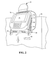
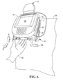
- the integrated device 77 is movable between a retracted or closed position (as shown in Fig. 2 ) to an extended or open position (as shown in Fig. 3 ).
- a writing surface 79 of the signature capture pad 78 can be easily viewed by a customer in a standing position at the checkout station 50.
- the writing surface 79 of the signature capture pad 78 can be easily viewed by a customer in a seated position at the checkout station 50.
- components of the adjustable mounting apparatus 30 includes: a fixed mount portion 1; a slidable mount portion 2; a first plastic grommet 3; a second plastic grommet 4; four plastic spacers with shoulder 5; two cable clamps 6; two steel, blue zinc nuts 7; a spadehead thumbscrew 8; four threadlock screws 9; a pair of Phil flat screws 10; a pair of neodymium disc magnets 11; a pair of steel cups for magnets 12; and four wing nuts 13.
- a first one of the spacers 5 and a first one of the screws 9 are connected and slide within a first elongate opening 31; a second one of the spacers 5 and a second one of the screws 9 are connected and slide within a second elongate opening 32; a third one of the spacers 5 and a third one of the screws 9 are connected and slide within a first arcuate opening 33; and a fourth one of the spacers 5 and a fourth one of the screws 9 are connected and slide within a second arcuate opening 34.
- the four pairs of spacers 5 and screws 9 are held together with a suitable threadlike-type adhesive material such as Loctite 290 (trademark).
- the adjustable mounting apparatus 30 described hereinabove is without any swiveling parts.
- the apparatus 30 provides a non-swiveling type of mechanism in which a peripheral device (such as the integrated device 77 described hereinabove) can be discretely positioned such that both the location and the viewing angle of the writing surface 79 of the signature capture pad 78 are adjusted at the same time. Since the adjustable mounting apparatus 30 is swivelless, there is no need to re-adjust parts which swivel relative to each other and change position relative to each other over time.
- the transaction receipt dispense slot 85 is not blocked when adjustable mounting apparatus 30 is in either the retracted position shown in Fig. 2 or the extended position shown in Fig. 3 .
- the receipt dispense slot 85 is not blocked because the slidable mount portion 2 is not positioned in front of the slot.
- the receipt dispense slot 85 is also not blocked even though the slidable mount portion 2 is in front of the slot 85. This is because the slidable mount portion 2 is at a sufficient distance away from the slot 85 such that the slot is not blocked and a customer can still access the slot to remove a transaction receipt which has been dispensed.
- a standing customer can better view the writing surface 79 of the signature capture pad 78 when the apparatus 30 is in the retracted position of Fig. 2 and a seated customer can better view the writing surface 79 of the signature capture pad 78 when the apparatus 30 is in the extended position of Fig. 3 .
- location of the signature capture pad 78 complies with ADA guidelines.
- a simple process i.e., either lifting/pulling or lifting/pushing
- the adjustable mounting apparatus 30 may be used with other peripheral devices.
- peripheral devices include personal identification number (PIN) pads, magnetic stripe readers (MSRs), smart card readers (which can be of either the contact-type or the contactless-type), and customer interface displays (CIDs), and any combination of such peripheral devices.
- PIN personal identification number
- MSRs magnetic stripe readers
- CIDs customer interface displays
- the signature capture pad 78 and the card reader 76 may be separate from each other, or either one may be integrated with another peripheral device.
- fasteners in the form of threadlock screws 9 which slide within the first and second elongate openings 31, 32 and the first and second arcuate openings 33, 34, it is conceivable that other types of fasteners be used.
Landscapes
- Engineering & Computer Science (AREA)
- General Engineering & Computer Science (AREA)
- Business, Economics & Management (AREA)
- Mechanical Engineering (AREA)
- Accounting & Taxation (AREA)
- Finance (AREA)
- Economics (AREA)
- Development Economics (AREA)
- Strategic Management (AREA)
- Physics & Mathematics (AREA)
- General Business, Economics & Management (AREA)
- General Physics & Mathematics (AREA)
- Theoretical Computer Science (AREA)
- Cash Registers Or Receiving Machines (AREA)
Claims (6)
- Selbstbedienungs-Einzelhandelsposten-Checkout-Station (50), umfassend:eine Beschickungseinheit (54) und eine Kassentischeinheit (58);ein Peripheriegerät (77) zur Interaktion mit einem Kunden, während der Kunde eine Selbstbedienungs-Einzelhandelsposten-Checkout-Transaktion an der Station (50) ausführt; undeinen nicht schwenkbaren Halterungsmechanismus (30), der (i) einen verschiebbaren Halterungsabschnitt (2) umfasst, auf dem das Peripheriegerät (77) angebracht ist, und (ii) einen feststehenden Halterungsabschnitt (1), auf dem der verschiebbare Halterungsabschnitt (2) für eine gleitende Bewegung zwischen einer eingefahrenen Position, in der ein Kunde in einer stehenden Position an der Station (50) leichter mit dem Peripheriegerät (77) interagieren kann, und einer ausgefahrenen Position, in der ein Kunde in einer sitzenden Position an der Station (50) leichter mit dem Peripheriegerät (77) interagieren kann, abgestützt ist.
- Selbstbedienungs-Einzelhandelsposten-Checkout-Station (50) nach Anspruch 1, wobei (i) der feststehende Halterungsabschnitt eine längliche Öffnung (31 oder 32) aufweist, in der ein mit einem Abschnitt des verschiebbaren Halterungsabschnitts (2) verbundenes Befestigungselement (9) gleitet, und (ii) mindestens eine bogenförmige Öffnung (33 oder 34), in der ein mit einem anderen Abschnitt des verschiebbaren Halterungsabschnitts (2) verbundenes Befestigungselement (9) gleitet, sodass sich sowohl die räumliche Position als auch der Betrachtungswinkel des Peripheriegeräts (77) gleichzeitig ändern, wenn der verschiebbare Halterungsabschnitt (2) zwischen der eingefahrenen und der ausgefahrenen Position bewegt wird.
- Selbstbedienungs-Einzelhandelsposten-Checkout-Station (50) nach Anspruch 2, weiterhin umfassend einen Magneten (11), der an einem der Befestigungselemente (9) derart befestigt ist, dass (i) der verschiebbare Halterungsabschnitt (2) magnetisch an dem feststehenden Halterungsabschnitt (1) befestigt ist, wenn sich der verschiebbare Halterungsabschnitt (2) in der eingefahrenen Position befindet, und (ii) sich der verschiebbare Halterungsabschnitt (2) von dem feststehenden Halterungsabschnitt (1) weg bewegt, wenn der Kunde den verschiebbaren Halterungsabschnitt (2) anhebt und zieht, um den verschiebbaren Halterungsbschnitt (2) von der eingefahrenen Position in die ausgefahrene Position zu bewegen.
- Selbstbedienungs-Einzelhandelsposten-Checkout-Station (50) nach Anspruch 3, wobei sich der verschiebbare Halterungsabschnitt (2) zu dem feststehenden Halterungsabschnitt (1) bewegt, wenn der Kunde den verschiebbaren Halterungsabschnitt (2) anhebt und drückt, um den verschiebbaren Halterungsbschnitt (2) von der ausgefahrenen Position in die eingefahrene Position zu bewegen.
- Selbstbedienungs-Einzelhandelsposten-Checkout-Station (50) nach einem der Ansprüche 2 bis 4, wobei jedes der Befestigungselemente (9) eine gesicherte Schraube umfasst.
- Selbstbedienungs-Einzelhandelsposten-Checkout-Station (50) nach einem der vorangegangenen Ansprüche, wobei das Peripheriegerät (77) eine integrierte Vorrichtung umfasst, die einen Kartenleser (76) und ein Unterschriften-Erfassungs-Pad (79) umfasst.
Applications Claiming Priority (1)
| Application Number | Priority Date | Filing Date | Title |
|---|---|---|---|
| US12/817,253 US8321340B2 (en) | 2010-06-17 | 2010-06-17 | Adjustable mounting apparatus for a peripheral device of a self-service retail item checkout station |
Publications (3)
| Publication Number | Publication Date |
|---|---|
| EP2397743A2 EP2397743A2 (de) | 2011-12-21 |
| EP2397743A3 EP2397743A3 (de) | 2012-12-19 |
| EP2397743B1 true EP2397743B1 (de) | 2015-09-02 |
Family
ID=44583939
Family Applications (1)
| Application Number | Title | Priority Date | Filing Date |
|---|---|---|---|
| EP11168569.9A Active EP2397743B1 (de) | 2010-06-17 | 2011-06-02 | Einstellbare Montagevorrichtung für ein Peripheriegerät einer Warenregistrierstation im Selbstbedienungseinzelhandel |
Country Status (2)
| Country | Link |
|---|---|
| US (1) | US8321340B2 (de) |
| EP (1) | EP2397743B1 (de) |
Families Citing this family (6)
| Publication number | Priority date | Publication date | Assignee | Title |
|---|---|---|---|---|
| IT201900004019A1 (it) * | 2019-03-20 | 2020-09-20 | Microgeo S R L | Supporto per un dispositivo di rilevazione |
| CN112562107B (zh) * | 2020-11-17 | 2022-06-14 | 苏州伊伯菲信息科技有限公司 | 一种带有墙挂结构的考勤机 |
| US12590667B2 (en) | 2020-12-18 | 2026-03-31 | Ergonomic Solutions International Limited | Height adjustable holder for a multiplate |
| US11723480B2 (en) | 2021-08-04 | 2023-08-15 | Target Brands, Inc. | Self-checkout system |
| USD1027519S1 (en) | 2021-08-04 | 2024-05-21 | Target Brands, Inc. | Self-checkout station |
| FR3152561B1 (fr) * | 2023-08-29 | 2025-07-18 | Snef | Dispositif de fixation configuré pour solidariser un équipement électrique avec une paroi. |
Family Cites Families (16)
| Publication number | Priority date | Publication date | Assignee | Title |
|---|---|---|---|---|
| US4768744A (en) * | 1986-08-27 | 1988-09-06 | Richard Leeds | Apparatus for supporting a load in a dynamically balanced condition |
| US5713549A (en) * | 1995-05-22 | 1998-02-03 | Shieh; En-Ru | Monitor support device |
| US5842672A (en) * | 1996-06-07 | 1998-12-01 | Ergotron, Inc. | Mounting system for flat panel display, keyboard and stand |
| US5917741A (en) * | 1996-08-29 | 1999-06-29 | Intel Corporation | Method and apparatus for performing floating-point rounding operations for multiple precisions using incrementers |
| US6347776B1 (en) * | 2000-06-30 | 2002-02-19 | Po-An Chuang | Multi-directional mounting bracket |
| US6367756B1 (en) * | 2000-07-07 | 2002-04-09 | James Wang | Adjustable device support and anchor means arrangement |
| US6484987B2 (en) * | 2000-12-29 | 2002-11-26 | Bellsouth Intellectual Property Corporation | Mounting bracket |
| JP2002347474A (ja) * | 2001-05-29 | 2002-12-04 | Matsushita Electric Ind Co Ltd | 表示装置 |
| TW540981U (en) * | 2001-12-20 | 2003-07-01 | Mitac Int Corp | Display disposition device |
| US6592090B1 (en) * | 2002-08-23 | 2003-07-15 | Chin-Chu Li | Object supporting structure |
| US7322653B2 (en) * | 2003-06-13 | 2008-01-29 | Vlad Dragusin | Integrated videogaming and computer workstation |
| USD495713S1 (en) * | 2004-01-02 | 2004-09-07 | Decade Industries, Inc. | Display mount |
| JP5226316B2 (ja) * | 2004-10-19 | 2013-07-03 | エルゴトロン,インコーポレイティド | ディスプレイ取付システムおよび方法 |
| US7172114B2 (en) * | 2004-12-30 | 2007-02-06 | Hand Held Products, Inc. | Tamperproof point of sale transaction terminal |
| GB2427127A (en) * | 2005-06-16 | 2006-12-20 | Scanstrut Ltd | Mounting for a retractable user interface |
| US7641163B2 (en) * | 2005-10-21 | 2010-01-05 | Peerless Industries, Inc. | Tilt mounting system |
-
2010
- 2010-06-17 US US12/817,253 patent/US8321340B2/en active Active
-
2011
- 2011-06-02 EP EP11168569.9A patent/EP2397743B1/de active Active
Also Published As
| Publication number | Publication date |
|---|---|
| US8321340B2 (en) | 2012-11-27 |
| EP2397743A3 (de) | 2012-12-19 |
| EP2397743A2 (de) | 2011-12-21 |
| US20110313914A1 (en) | 2011-12-22 |
Similar Documents
| Publication | Publication Date | Title |
|---|---|---|
| EP1273250B1 (de) | Zwischen unterstützten und nicht unterstützten Konfigurationen verwandelbares Warenauszahlsystem | |
| US9741211B2 (en) | Checkout station | |
| EP2397743B1 (de) | Einstellbare Montagevorrichtung für ein Peripheriegerät einer Warenregistrierstation im Selbstbedienungseinzelhandel | |
| US8985444B2 (en) | Checkout stand with a barcode reader on a bagging end | |
| CA2197042C (en) | Self-service checkout system | |
| CA2578239C (en) | Rf point of purchase apparatus and method of using same | |
| US6394345B1 (en) | Checkout terminal and associated method having movable scanner | |
| US20040041021A1 (en) | Modular self checkout system | |
| US10748388B2 (en) | Sales data processing apparatus | |
| US6550582B2 (en) | Method and apparatus for processing a large number of items with a self-service checkout terminal | |
| US7059513B2 (en) | POS podium incorporating a short depth cash drawer | |
| US20090283593A1 (en) | Merchandise sales data processing apparatus | |
| EP1784717A2 (de) | Verkaufsstellen-abgabevorrichtung mit behälter und verfahren zu dessen nutzung | |
| JP5291688B2 (ja) | 袋保持装置及びチェックアウト装置 | |
| EP3970569A1 (de) | Kassenvorrichtung | |
| US9700159B2 (en) | Non-linear checkout stand | |
| US20110309142A1 (en) | Payment card reader apparatus and method of operating a payment card reader apparatus | |
| GB2457315A (en) | Self-service checkout terminal | |
| WO1999065000A1 (en) | Check-out apparatus | |
| KR102818593B1 (ko) | 멀티 포스 판매대 | |
| JP2549502B2 (ja) | 商品情報読取装置 | |
| EP3361458A1 (de) | Registrierkassenstation | |
| JP4877949B2 (ja) | チェックアウト装置 | |
| JP2026023607A (ja) | チェックアウトシステム |
Legal Events
| Date | Code | Title | Description |
|---|---|---|---|
| AK | Designated contracting states |
Kind code of ref document: A2 Designated state(s): AL AT BE BG CH CY CZ DE DK EE ES FI FR GB GR HR HU IE IS IT LI LT LU LV MC MK MT NL NO PL PT RO RS SE SI SK SM TR |
|
| AX | Request for extension of the european patent |
Extension state: BA ME |
|
| PUAI | Public reference made under article 153(3) epc to a published international application that has entered the european phase |
Free format text: ORIGINAL CODE: 0009012 |
|
| PUAL | Search report despatched |
Free format text: ORIGINAL CODE: 0009013 |
|
| AK | Designated contracting states |
Kind code of ref document: A3 Designated state(s): AL AT BE BG CH CY CZ DE DK EE ES FI FR GB GR HR HU IE IS IT LI LT LU LV MC MK MT NL NO PL PT RO RS SE SI SK SM TR |
|
| AX | Request for extension of the european patent |
Extension state: BA ME |
|
| RIC1 | Information provided on ipc code assigned before grant |
Ipc: F16M 11/10 20060101AFI20121114BHEP Ipc: F16M 13/02 20060101ALI20121114BHEP |
|
| 17P | Request for examination filed |
Effective date: 20130619 |
|
| RBV | Designated contracting states (corrected) |
Designated state(s): AL AT BE BG CH CY CZ DE DK EE ES FI FR GB GR HR HU IE IS IT LI LT LU LV MC MK MT NL NO PL PT RO RS SE SI SK SM TR |
|
| 17Q | First examination report despatched |
Effective date: 20140605 |
|
| GRAP | Despatch of communication of intention to grant a patent |
Free format text: ORIGINAL CODE: EPIDOSNIGR1 |
|
| INTG | Intention to grant announced |
Effective date: 20150610 |
|
| GRAS | Grant fee paid |
Free format text: ORIGINAL CODE: EPIDOSNIGR3 |
|
| GRAA | (expected) grant |
Free format text: ORIGINAL CODE: 0009210 |
|
| AK | Designated contracting states |
Kind code of ref document: B1 Designated state(s): AL AT BE BG CH CY CZ DE DK EE ES FI FR GB GR HR HU IE IS IT LI LT LU LV MC MK MT NL NO PL PT RO RS SE SI SK SM TR |
|
| REG | Reference to a national code |
Ref country code: GB Ref legal event code: FG4D |
|
| REG | Reference to a national code |
Ref country code: DE Ref legal event code: R084 Ref document number: 602011019311 Country of ref document: DE |
|
| REG | Reference to a national code |
Ref country code: AT Ref legal event code: REF Ref document number: 746833 Country of ref document: AT Kind code of ref document: T Effective date: 20150915 Ref country code: CH Ref legal event code: EP |
|
| REG | Reference to a national code |
Ref country code: IE Ref legal event code: FG4D |
|
| REG | Reference to a national code |
Ref country code: DE Ref legal event code: R096 Ref document number: 602011019311 Country of ref document: DE |
|
| REG | Reference to a national code |
Ref country code: GB Ref legal event code: 746 Effective date: 20150930 |
|
| REG | Reference to a national code |
Ref country code: AT Ref legal event code: MK05 Ref document number: 746833 Country of ref document: AT Kind code of ref document: T Effective date: 20150902 |
|
| PG25 | Lapsed in a contracting state [announced via postgrant information from national office to epo] |
Ref country code: GR Free format text: LAPSE BECAUSE OF FAILURE TO SUBMIT A TRANSLATION OF THE DESCRIPTION OR TO PAY THE FEE WITHIN THE PRESCRIBED TIME-LIMIT Effective date: 20151203 Ref country code: LV Free format text: LAPSE BECAUSE OF FAILURE TO SUBMIT A TRANSLATION OF THE DESCRIPTION OR TO PAY THE FEE WITHIN THE PRESCRIBED TIME-LIMIT Effective date: 20150902 Ref country code: FI Free format text: LAPSE BECAUSE OF FAILURE TO SUBMIT A TRANSLATION OF THE DESCRIPTION OR TO PAY THE FEE WITHIN THE PRESCRIBED TIME-LIMIT Effective date: 20150902 Ref country code: LT Free format text: LAPSE BECAUSE OF FAILURE TO SUBMIT A TRANSLATION OF THE DESCRIPTION OR TO PAY THE FEE WITHIN THE PRESCRIBED TIME-LIMIT Effective date: 20150902 Ref country code: NO Free format text: LAPSE BECAUSE OF FAILURE TO SUBMIT A TRANSLATION OF THE DESCRIPTION OR TO PAY THE FEE WITHIN THE PRESCRIBED TIME-LIMIT Effective date: 20151202 |
|
| REG | Reference to a national code |
Ref country code: LT Ref legal event code: MG4D Ref country code: NL Ref legal event code: MP Effective date: 20150902 |
|
| PG25 | Lapsed in a contracting state [announced via postgrant information from national office to epo] |
Ref country code: AT Free format text: LAPSE BECAUSE OF FAILURE TO SUBMIT A TRANSLATION OF THE DESCRIPTION OR TO PAY THE FEE WITHIN THE PRESCRIBED TIME-LIMIT Effective date: 20150902 Ref country code: PL Free format text: LAPSE BECAUSE OF FAILURE TO SUBMIT A TRANSLATION OF THE DESCRIPTION OR TO PAY THE FEE WITHIN THE PRESCRIBED TIME-LIMIT Effective date: 20150902 Ref country code: ES Free format text: LAPSE BECAUSE OF FAILURE TO SUBMIT A TRANSLATION OF THE DESCRIPTION OR TO PAY THE FEE WITHIN THE PRESCRIBED TIME-LIMIT Effective date: 20150902 Ref country code: SE Free format text: LAPSE BECAUSE OF FAILURE TO SUBMIT A TRANSLATION OF THE DESCRIPTION OR TO PAY THE FEE WITHIN THE PRESCRIBED TIME-LIMIT Effective date: 20150902 Ref country code: RS Free format text: LAPSE BECAUSE OF FAILURE TO SUBMIT A TRANSLATION OF THE DESCRIPTION OR TO PAY THE FEE WITHIN THE PRESCRIBED TIME-LIMIT Effective date: 20150902 |
|
| PG25 | Lapsed in a contracting state [announced via postgrant information from national office to epo] |
Ref country code: SK Free format text: LAPSE BECAUSE OF FAILURE TO SUBMIT A TRANSLATION OF THE DESCRIPTION OR TO PAY THE FEE WITHIN THE PRESCRIBED TIME-LIMIT Effective date: 20150902 Ref country code: CZ Free format text: LAPSE BECAUSE OF FAILURE TO SUBMIT A TRANSLATION OF THE DESCRIPTION OR TO PAY THE FEE WITHIN THE PRESCRIBED TIME-LIMIT Effective date: 20150902 Ref country code: EE Free format text: LAPSE BECAUSE OF FAILURE TO SUBMIT A TRANSLATION OF THE DESCRIPTION OR TO PAY THE FEE WITHIN THE PRESCRIBED TIME-LIMIT Effective date: 20150902 Ref country code: NL Free format text: LAPSE BECAUSE OF FAILURE TO SUBMIT A TRANSLATION OF THE DESCRIPTION OR TO PAY THE FEE WITHIN THE PRESCRIBED TIME-LIMIT Effective date: 20150902 Ref country code: IT Free format text: LAPSE BECAUSE OF FAILURE TO SUBMIT A TRANSLATION OF THE DESCRIPTION OR TO PAY THE FEE WITHIN THE PRESCRIBED TIME-LIMIT Effective date: 20150902 Ref country code: IS Free format text: LAPSE BECAUSE OF FAILURE TO SUBMIT A TRANSLATION OF THE DESCRIPTION OR TO PAY THE FEE WITHIN THE PRESCRIBED TIME-LIMIT Effective date: 20160102 |
|
| PG25 | Lapsed in a contracting state [announced via postgrant information from national office to epo] |
Ref country code: RO Free format text: LAPSE BECAUSE OF FAILURE TO SUBMIT A TRANSLATION OF THE DESCRIPTION OR TO PAY THE FEE WITHIN THE PRESCRIBED TIME-LIMIT Effective date: 20150902 Ref country code: PT Free format text: LAPSE BECAUSE OF FAILURE TO SUBMIT A TRANSLATION OF THE DESCRIPTION OR TO PAY THE FEE WITHIN THE PRESCRIBED TIME-LIMIT Effective date: 20160104 |
|
| REG | Reference to a national code |
Ref country code: DE Ref legal event code: R097 Ref document number: 602011019311 Country of ref document: DE |
|
| REG | Reference to a national code |
Ref country code: FR Ref legal event code: PLFP Year of fee payment: 6 |
|
| PLBE | No opposition filed within time limit |
Free format text: ORIGINAL CODE: 0009261 |
|
| STAA | Information on the status of an ep patent application or granted ep patent |
Free format text: STATUS: NO OPPOSITION FILED WITHIN TIME LIMIT |
|
| 26N | No opposition filed |
Effective date: 20160603 |
|
| PG25 | Lapsed in a contracting state [announced via postgrant information from national office to epo] |
Ref country code: DK Free format text: LAPSE BECAUSE OF FAILURE TO SUBMIT A TRANSLATION OF THE DESCRIPTION OR TO PAY THE FEE WITHIN THE PRESCRIBED TIME-LIMIT Effective date: 20150902 Ref country code: SI Free format text: LAPSE BECAUSE OF FAILURE TO SUBMIT A TRANSLATION OF THE DESCRIPTION OR TO PAY THE FEE WITHIN THE PRESCRIBED TIME-LIMIT Effective date: 20150902 |
|
| PG25 | Lapsed in a contracting state [announced via postgrant information from national office to epo] |
Ref country code: BE Free format text: LAPSE BECAUSE OF FAILURE TO SUBMIT A TRANSLATION OF THE DESCRIPTION OR TO PAY THE FEE WITHIN THE PRESCRIBED TIME-LIMIT Effective date: 20150902 |
|
| PG25 | Lapsed in a contracting state [announced via postgrant information from national office to epo] |
Ref country code: MC Free format text: LAPSE BECAUSE OF FAILURE TO SUBMIT A TRANSLATION OF THE DESCRIPTION OR TO PAY THE FEE WITHIN THE PRESCRIBED TIME-LIMIT Effective date: 20150902 |
|
| REG | Reference to a national code |
Ref country code: CH Ref legal event code: PL |
|
| REG | Reference to a national code |
Ref country code: IE Ref legal event code: MM4A |
|
| PG25 | Lapsed in a contracting state [announced via postgrant information from national office to epo] |
Ref country code: CH Free format text: LAPSE BECAUSE OF NON-PAYMENT OF DUE FEES Effective date: 20160630 Ref country code: LI Free format text: LAPSE BECAUSE OF NON-PAYMENT OF DUE FEES Effective date: 20160630 |
|
| PG25 | Lapsed in a contracting state [announced via postgrant information from national office to epo] |
Ref country code: IE Free format text: LAPSE BECAUSE OF NON-PAYMENT OF DUE FEES Effective date: 20160602 |
|
| REG | Reference to a national code |
Ref country code: FR Ref legal event code: PLFP Year of fee payment: 7 |
|
| PG25 | Lapsed in a contracting state [announced via postgrant information from national office to epo] |
Ref country code: CY Free format text: LAPSE BECAUSE OF FAILURE TO SUBMIT A TRANSLATION OF THE DESCRIPTION OR TO PAY THE FEE WITHIN THE PRESCRIBED TIME-LIMIT Effective date: 20150902 Ref country code: SM Free format text: LAPSE BECAUSE OF FAILURE TO SUBMIT A TRANSLATION OF THE DESCRIPTION OR TO PAY THE FEE WITHIN THE PRESCRIBED TIME-LIMIT Effective date: 20150902 Ref country code: HU Free format text: LAPSE BECAUSE OF FAILURE TO SUBMIT A TRANSLATION OF THE DESCRIPTION OR TO PAY THE FEE WITHIN THE PRESCRIBED TIME-LIMIT; INVALID AB INITIO Effective date: 20110602 |
|
| REG | Reference to a national code |
Ref country code: FR Ref legal event code: PLFP Year of fee payment: 8 |
|
| PG25 | Lapsed in a contracting state [announced via postgrant information from national office to epo] |
Ref country code: LU Free format text: LAPSE BECAUSE OF NON-PAYMENT OF DUE FEES Effective date: 20160602 Ref country code: HR Free format text: LAPSE BECAUSE OF FAILURE TO SUBMIT A TRANSLATION OF THE DESCRIPTION OR TO PAY THE FEE WITHIN THE PRESCRIBED TIME-LIMIT Effective date: 20150902 Ref country code: MT Free format text: LAPSE BECAUSE OF NON-PAYMENT OF DUE FEES Effective date: 20160630 Ref country code: TR Free format text: LAPSE BECAUSE OF FAILURE TO SUBMIT A TRANSLATION OF THE DESCRIPTION OR TO PAY THE FEE WITHIN THE PRESCRIBED TIME-LIMIT Effective date: 20150902 Ref country code: MK Free format text: LAPSE BECAUSE OF FAILURE TO SUBMIT A TRANSLATION OF THE DESCRIPTION OR TO PAY THE FEE WITHIN THE PRESCRIBED TIME-LIMIT Effective date: 20150902 |
|
| PG25 | Lapsed in a contracting state [announced via postgrant information from national office to epo] |
Ref country code: BG Free format text: LAPSE BECAUSE OF FAILURE TO SUBMIT A TRANSLATION OF THE DESCRIPTION OR TO PAY THE FEE WITHIN THE PRESCRIBED TIME-LIMIT Effective date: 20150902 |
|
| PG25 | Lapsed in a contracting state [announced via postgrant information from national office to epo] |
Ref country code: AL Free format text: LAPSE BECAUSE OF FAILURE TO SUBMIT A TRANSLATION OF THE DESCRIPTION OR TO PAY THE FEE WITHIN THE PRESCRIBED TIME-LIMIT Effective date: 20150902 |
|
| REG | Reference to a national code |
Ref country code: DE Ref legal event code: R081 Ref document number: 602011019311 Country of ref document: DE Owner name: NCR VOYIX CORP., ATLANTA, US Free format text: FORMER OWNER: NCR CORP., DULUTH, GA., US Ref country code: DE Ref legal event code: R082 Ref document number: 602011019311 Country of ref document: DE Representative=s name: V. BEZOLD & PARTNER PATENTANWAELTE - PARTG MBB, DE Ref country code: DE Ref legal event code: R081 Ref document number: 602011019311 Country of ref document: DE Owner name: NCR CORPORATION, ATLANTA, US Free format text: FORMER OWNER: NCR CORP., DULUTH, GA., US |
|
| P01 | Opt-out of the competence of the unified patent court (upc) registered |
Effective date: 20230507 |
|
| REG | Reference to a national code |
Ref country code: DE Ref legal event code: R081 Ref document number: 602011019311 Country of ref document: DE Owner name: NCR VOYIX CORP., ATLANTA, US Free format text: FORMER OWNER: NCR CORPORATION, ATLANTA, GA, US |
|
| PGFP | Annual fee paid to national office [announced via postgrant information from national office to epo] |
Ref country code: DE Payment date: 20250627 Year of fee payment: 15 |
|
| PGFP | Annual fee paid to national office [announced via postgrant information from national office to epo] |
Ref country code: GB Payment date: 20250627 Year of fee payment: 15 |
|
| PGFP | Annual fee paid to national office [announced via postgrant information from national office to epo] |
Ref country code: FR Payment date: 20250625 Year of fee payment: 15 |