US9700159B2 - Non-linear checkout stand - Google Patents
Non-linear checkout stand Download PDFInfo
- Publication number
- US9700159B2 US9700159B2 US13/562,737 US201213562737A US9700159B2 US 9700159 B2 US9700159 B2 US 9700159B2 US 201213562737 A US201213562737 A US 201213562737A US 9700159 B2 US9700159 B2 US 9700159B2
- Authority
- US
- United States
- Prior art keywords
- items
- housing
- checkout stand
- tunnel
- checkout
- Prior art date
- Legal status (The legal status is an assumption and is not a legal conclusion. Google has not performed a legal analysis and makes no representation as to the accuracy of the status listed.)
- Active, expires
Links
Images


Classifications
-
- A—HUMAN NECESSITIES
- A47—FURNITURE; DOMESTIC ARTICLES OR APPLIANCES; COFFEE MILLS; SPICE MILLS; SUCTION CLEANERS IN GENERAL
- A47F—SPECIAL FURNITURE, FITTINGS, OR ACCESSORIES FOR SHOPS, STOREHOUSES, BARS, RESTAURANTS OR THE LIKE; PAYING COUNTERS
- A47F9/00—Shop, bar, bank or like counters
- A47F9/02—Paying counters
- A47F9/04—Check-out counters, e.g. for self-service stores
- A47F9/046—Arrangement of recording means in or on check-out counters
- A47F9/047—Arrangement of recording means in or on check-out counters for recording self-service articles without cashier or assistant
- A47F9/048—Arrangement of recording means in or on check-out counters for recording self-service articles without cashier or assistant automatically
-
- G—PHYSICS
- G06—COMPUTING OR CALCULATING; COUNTING
- G06Q—INFORMATION AND COMMUNICATION TECHNOLOGY [ICT] SPECIALLY ADAPTED FOR ADMINISTRATIVE, COMMERCIAL, FINANCIAL, MANAGERIAL OR SUPERVISORY PURPOSES; SYSTEMS OR METHODS SPECIALLY ADAPTED FOR ADMINISTRATIVE, COMMERCIAL, FINANCIAL, MANAGERIAL OR SUPERVISORY PURPOSES, NOT OTHERWISE PROVIDED FOR
- G06Q30/00—Commerce
Definitions
- the present invention relates to checkout systems and methods and more specifically to a non-linear checkout stand.
- checkout stands are generally rectangular in shape and move items along a linear path. These checkout stands may include a linear conveyor belt for moving items from a receiving end to an operator station.
- the operator station may include a transaction terminal including a barcode reader for identifying the items somewhere in the middle of the checkout stand.
- the transaction terminal enters the items into a purchase transaction.
- items may pass through a tunnel in which the barcode reader is located.
- a takeaway belt along the linear path moves the items from the operator station to a bagging end.
- a plurality of these checkout stands may be arranged in parallel, with linear customer paths or checkout lanes in between.
- a non-linear checkout stand is provided.
- An example checkout stand includes a housing including a first end and a second end, a conveyor for transporting items in a plurality of different directions along a non-linear path connecting the first end to the second end, and an item identifier within the housing on the non-linear path for automatically identifying the items.
- An example computerized method of operating a checkout stand to process items during a transaction includes operating a conveyor to transport items in a plurality of different directions along a non-linear path from a first end of a checkout stand housing where the items are placed by a customer to a second end of the checkout stand housing where the items are removed by the customer, and receiving identification information associated with the items from an item identifier in the housing on the non-linear path.
- FIG. 1 is a perspective view of an example checkout stand.
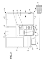
- FIG. 2 is a top view of the example checkout stand with a tunnel structure removed.
- FIG. 3 is a perspective view of another example checkout stand.
- Checkout stand 10 includes a generally U-shaped housing 20 having adjacent input and output ends 22 and 24 .
- Transaction terminal 12 is located between ends 22 and 24 .
- Checkout stand 10 may be suited for use by a customer as a self-service checkout station or by an attendant as an assisted service checkout station.
- Housing 20 includes conveyor 40 and tunnel cover 50 .
- Conveyor 40 transports items from input end 22 to output end 24 along a generally U-shaped path.
- Conveyer 40 may include one or more sections.
- Conveyor 40 may include four straight sections 42 , 44 , 46 , and 48 . Corners of housing 20 are generally square to accommodate straight conveyor belts.
- Conveyor section 42 transports items to conveyor section 44 , which transports the items to conveyor section 46 which transports the items to conveyor section 48 .
- conveyor sections 42 - 48 include belts and one or motors for moving the belts.
- Tunnel cover 50 covers a portion of the U-shaped path and conveyor 40 and defines a tunnel 52 .
- the entry and exit apertures of the tunnel may vary in location.
- the entry and exit apertures of the tunnel may face the input and output ends 22 and 24 , respectively ( FIG. 1 ).
- the entry and exit apertures may face in different directions, the entry aperture facing the input end 22 and the exit aperture facing perpendicular to output end 24 ( FIG. 3 ).
- Housing 20 includes one or more item identifiers 26 within tunnel 52 .
- Item identifier 26 is coupled to transaction terminal 12 .
- item identifier 26 may include a barcode reader for reading barcodes on items.
- item identifier 26 may include a radio frequency identification (RFID) label reader for reading RFID labels on the items.
- RFID radio frequency identification
- Another example item identifier 26 may include a camera for capturing images of items, such as produce items.
- Housing 20 further includes one or more scales 28 below conveyor 40 and within tunnel 52 for weighing items.
- Scale 28 weighs produce items and is coupled to transaction terminal 12 .
- Transaction terminal 12 uses the weight information to determine the price of the produce items.
- Transaction terminal 12 may also use scale 28 to weigh other items in order to verify item identification information from item identifier 26 .
- Housing 20 may include a bagging station 30 at output end 24 including a bag rack 32 and bag shelf 34 for supporting bags of items. Conveyor 40 causes items to accumulate at output end 24 to await bagging. Housing 20 may include a depression or bucket 36 at output end 24 for capturing the items.
- a customer display 38 may be located at input end 22 .
- Transaction terminal 12 is located between input end 22 and output end 24 .
- Transaction terminal 12 controls operation of checkout stand 10 and its components.
- Transaction terminal 12 includes one or more processors, memory, and program and data storage.
- Transaction terminal 12 may execute an operating system such as a Microsoft or other operating system.
- Transaction terminal 12 may execute transaction processing and other software that may be stored in a computer readable medium, such as a memory.
- Transaction terminal 12 may be coupled to other computers, including an in-store server, via a network.
- Transaction terminal 12 further includes a display and an input device, which may be combined as a touch screen 60 .
- Transaction terminal 12 additionally includes components and peripherals necessary to accomplish its purpose, including graphics circuitry for connecting to the display, network circuitry for connecting to a network, peripheral connection circuitry for connecting to peripherals including item identifier 26 , scale 28 , and customer display 38 , and for connecting to additional peripherals including one or more payment devices 62 , a printer 64 , an indicator 66 , a security camera 68 .
- Payment device 62 may include one or more of a card reader for reading loyalty cards and payment cards, such as credit cards and debit cards, a currency dispenser and/or a currency acceptor, such as a currency recycler, and a coin dispenser and/or coin acceptor.
- a card reader for reading loyalty cards and payment cards, such as credit cards and debit cards
- a currency dispenser and/or a currency acceptor such as a currency recycler
- a coin dispenser and/or coin acceptor includes a payment terminal with a card reader, a keypad, and a display.
- Another example payment device includes a signature capture peripheral with a card reader.
- Printer 64 prints a receipt for a transaction.
- Indicator 66 may include on or more lights for signaling an attendant or security person.
- the lights may be mounted on a pole.
- Security camera 68 allows a remote attendant or security person to monitor operator activity at checkout stand 10 and transaction terminal 12 .
- checkout stand 10 In an example self-service checkout mode of operation in which checkout stand 10 is located in a store where a customer is purchasing items, the customer positions a shopping cart 70 ( FIG. 2 ) containing the items adjacent input end 22 for unloading. The customer first selects a begin transaction option via touch screen 60 . Transaction terminal 12 operates conveyor 40 .
- Conveyor section 42 transports the items to the entrance of tunnel 52 and conveyor section 44 .
- Conveyor section 44 transports the items to item identifier 26 where the items are identified. Item identifier 26 may be located between conveyor sections 44 and 46 .
- the items pass to conveyor section 46 where the items are weighed by scale 28 .
- Conveyor section 46 transports the items to conveyor section 48 , which transports the items out of tunnel 52 and into bucket 36 to await bagging.
- Transaction terminal 12 After the customer has placed all of the items on conveyor section 42 , the customer moves cart 70 to transaction terminal 12 , where the customer is able to view item identification and other information displayed by customer display 38 .
- Transaction terminal 12 obtains the item identification information from item identifier 26 and obtains prices for the items, for example, from a price look-up file at an in-store server.
- Transaction terminal 12 displays the items and their prices on customer display 38 .
- Transaction terminal 12 stops conveyor 40 , tallies the items, and displays payment options. The customer selects one of the payment options and provides payment via payment device 62 . Transaction terminal 12 processes the payment and causes printer 64 to print a receipt.
- the customer moves cart 70 to bagging station 30 .
- the customer removes the items from bucket 36 , bags the items, and places bags of items in cart 70 .
- the customer moves cart 70 away from checkout stand 10 and exits the store.
- Checkout stand 10 includes housing 90 which is again generally U-shaped and has adjacent input and output ends 92 and 94 .
- Transaction terminal 12 is located between ends 92 and 94 an operates as described in the embodiment of FIGS. 1-2 .
- Housing 90 differs from housing 20 of FIGS. 1-2 in that one of the corners has been replaced with a curved section.
- the curved section includes a curved conveyor section 104 and a curved tunnel cover 110 .
- Conveyor 100 also includes conveyor section 102 at input end 92 and convey section 106 at output end 94 .
- Conveyor section 102 transports items from input end 92 to conveyor section 104 where they enter curved tunnel 112 .
- Conveyor section 104 transports the items to conveyor section 106 where they exit curved tunnel 112 .
- this embodiment includes one or more item identifiers 26 and one or more scales 28 within curved tunnel 112 .
- the embodiment further includes bucket 36 at output end 94 , bagging station 30 at output end 94 , indicator 66 , camera 68 , and customer display 38 , which is mounted to curved tunnel cover 110 , near the entrance to curved tunnel 112 .
- the generally square footprint occupied by checkout stand 10 and transaction terminal 12 offers retailers additional options for configuring a store.
- the checkout lane adjacent checkout stand 10 defining the path of cart 70 is linear, but since the distance between the input and output ends is shorter, a customer has improved control over items that are waiting to be bagged and placed in cart 70 .
Landscapes
- Business, Economics & Management (AREA)
- Accounting & Taxation (AREA)
- Development Economics (AREA)
- Economics (AREA)
- Finance (AREA)
- Marketing (AREA)
- Strategic Management (AREA)
- Physics & Mathematics (AREA)
- General Business, Economics & Management (AREA)
- General Physics & Mathematics (AREA)
- Engineering & Computer Science (AREA)
- Theoretical Computer Science (AREA)
- Cash Registers Or Receiving Machines (AREA)
Abstract
Description
Claims (19)
Priority Applications (1)
| Application Number | Priority Date | Filing Date | Title |
|---|---|---|---|
| US13/562,737 US9700159B2 (en) | 2012-07-31 | 2012-07-31 | Non-linear checkout stand |
Applications Claiming Priority (1)
| Application Number | Priority Date | Filing Date | Title |
|---|---|---|---|
| US13/562,737 US9700159B2 (en) | 2012-07-31 | 2012-07-31 | Non-linear checkout stand |
Publications (2)
| Publication Number | Publication Date |
|---|---|
| US20140040057A1 US20140040057A1 (en) | 2014-02-06 |
| US9700159B2 true US9700159B2 (en) | 2017-07-11 |
Family
ID=50026419
Family Applications (1)
| Application Number | Title | Priority Date | Filing Date |
|---|---|---|---|
| US13/562,737 Active 2033-06-06 US9700159B2 (en) | 2012-07-31 | 2012-07-31 | Non-linear checkout stand |
Country Status (1)
| Country | Link |
|---|---|
| US (1) | US9700159B2 (en) |
Families Citing this family (4)
| Publication number | Priority date | Publication date | Assignee | Title |
|---|---|---|---|---|
| JP5788424B2 (en) * | 2013-03-04 | 2015-09-30 | 東芝テック株式会社 | Store system |
| USD976626S1 (en) * | 2020-02-06 | 2023-01-31 | Hanwha Techwin Co., Ltd. | Checkout stand |
| USD1014159S1 (en) * | 2020-04-10 | 2024-02-13 | Walmart Apollo, Llc | Dogleg modular bagging area extension device |
| USD1026516S1 (en) * | 2022-06-28 | 2024-05-14 | Toshiba Global Commerce Solutions Holdings Corporation | Self-checkout station |
Citations (5)
| Publication number | Priority date | Publication date | Assignee | Title |
|---|---|---|---|---|
| US4593194A (en) * | 1983-10-05 | 1986-06-03 | Quantum Corporation | Optical encoder with digital gain compensation controlling source intensity |
| US6329139B1 (en) * | 1995-04-25 | 2001-12-11 | Discovery Partners International | Automated sorting system for matrices with memory |
| US8054218B2 (en) * | 1998-09-11 | 2011-11-08 | Metrologic Instruments, Inc. | Remotely-alterable electronic-ink based display device employing an integrated circuit structure having a GPS signal receiver and programmed processor for locally determining display device position and transmitting determined position information to a remote activator module |
| US8069971B2 (en) * | 2006-08-31 | 2011-12-06 | Martin Engineering Company | Bulk material handling system and control |
| US20130346302A1 (en) * | 2012-06-20 | 2013-12-26 | Visa International Service Association | Remote Portal Bill Payment Platform Apparatuses, Methods and Systems |
-
2012
- 2012-07-31 US US13/562,737 patent/US9700159B2/en active Active
Patent Citations (5)
| Publication number | Priority date | Publication date | Assignee | Title |
|---|---|---|---|---|
| US4593194A (en) * | 1983-10-05 | 1986-06-03 | Quantum Corporation | Optical encoder with digital gain compensation controlling source intensity |
| US6329139B1 (en) * | 1995-04-25 | 2001-12-11 | Discovery Partners International | Automated sorting system for matrices with memory |
| US8054218B2 (en) * | 1998-09-11 | 2011-11-08 | Metrologic Instruments, Inc. | Remotely-alterable electronic-ink based display device employing an integrated circuit structure having a GPS signal receiver and programmed processor for locally determining display device position and transmitting determined position information to a remote activator module |
| US8069971B2 (en) * | 2006-08-31 | 2011-12-06 | Martin Engineering Company | Bulk material handling system and control |
| US20130346302A1 (en) * | 2012-06-20 | 2013-12-26 | Visa International Service Association | Remote Portal Bill Payment Platform Apparatuses, Methods and Systems |
Also Published As
| Publication number | Publication date |
|---|---|
| US20140040057A1 (en) | 2014-02-06 |
Similar Documents
| Publication | Publication Date | Title |
|---|---|---|
| US10621441B2 (en) | Portable computing device installed in or mountable to a shopping cart | |
| CN112037439B (en) | Information processing apparatus and control method thereof, readable storage medium, and electronic device | |
| EP2381409A2 (en) | System for self-service shopping and trolley thereof | |
| US8985444B2 (en) | Checkout stand with a barcode reader on a bagging end | |
| CA2197042C (en) | Self-service checkout system | |
| US7048184B2 (en) | Multiple self-checkout system having integrated payment device | |
| US20120221423A1 (en) | Commodity carrier | |
| US20130153656A1 (en) | Checkout Station | |
| CN108777045A (en) | Shopping settlement method, system and purchase system | |
| JP7723501B2 (en) | Sales Management System | |
| KR101742067B1 (en) | System for goods automatic recognition cart and the payment using the cart | |
| US8796564B2 (en) | Produce transaction system and method including a scale and a computer separate from a checkout computer | |
| WO2019045598A1 (en) | System for checking and identifying an article of merchandise in a shop | |
| US9700159B2 (en) | Non-linear checkout stand | |
| JP2007034789A (en) | Shopping cart and shopping system | |
| CN102521768A (en) | A system that automatically detects the quantity of goods and calculates the cost | |
| JP6863296B2 (en) | Information processing equipment, information processing methods, and programs | |
| JP7163144B2 (en) | Merchandise sales system, shopping cart and merchandise sales method | |
| JP5463247B2 (en) | Self-checkout terminal and program | |
| RU2684490C2 (en) | Method and system of retail sale of goods | |
| JP2018018421A (en) | Commodity sales data processing system and program | |
| GB2447051A (en) | Automated shopping system using RFID tags | |
| CN112508592A (en) | Area migration prediction device and storage medium | |
| CN112396776A (en) | Self-checkout terminal, method and non-transitory computer-readable medium | |
| KR101701111B1 (en) | Cart for auto calculating |
Legal Events
| Date | Code | Title | Description |
|---|---|---|---|
| AS | Assignment |
Owner name: NCR CORPORATION, GEORGIA Free format text: ASSIGNMENT OF ASSIGNORS INTEREST;ASSIGNORS:CALDERON, FERDINAND;DELOS ANGELES, JASON;REEL/FRAME:028686/0383 Effective date: 20120731 |
|
| AS | Assignment |
Owner name: JPMORGAN CHASE BANK, N.A., AS ADMINISTRATIVE AGENT, ILLINOIS Free format text: SECURITY AGREEMENT;ASSIGNORS:NCR CORPORATION;NCR INTERNATIONAL, INC.;REEL/FRAME:032034/0010 Effective date: 20140106 Owner name: JPMORGAN CHASE BANK, N.A., AS ADMINISTRATIVE AGENT Free format text: SECURITY AGREEMENT;ASSIGNORS:NCR CORPORATION;NCR INTERNATIONAL, INC.;REEL/FRAME:032034/0010 Effective date: 20140106 |
|
| AS | Assignment |
Owner name: JPMORGAN CHASE BANK, N.A., ILLINOIS Free format text: SECURITY AGREEMENT;ASSIGNORS:NCR CORPORATION;NCR INTERNATIONAL, INC.;REEL/FRAME:038646/0001 Effective date: 20160331 |
|
| STCF | Information on status: patent grant |
Free format text: PATENTED CASE |
|
| MAFP | Maintenance fee payment |
Free format text: PAYMENT OF MAINTENANCE FEE, 4TH YEAR, LARGE ENTITY (ORIGINAL EVENT CODE: M1551); ENTITY STATUS OF PATENT OWNER: LARGE ENTITY Year of fee payment: 4 |
|
| AS | Assignment |
Owner name: NCR VOYIX CORPORATION, GEORGIA Free format text: RELEASE OF PATENT SECURITY INTEREST;ASSIGNOR:JPMORGAN CHASE BANK, N.A., AS ADMINISTRATIVE AGENT;REEL/FRAME:065346/0531 Effective date: 20231016 Owner name: BANK OF AMERICA, N.A., AS ADMINISTRATIVE AGENT, NORTH CAROLINA Free format text: SECURITY INTEREST;ASSIGNOR:NCR VOYIX CORPORATION;REEL/FRAME:065346/0168 Effective date: 20231016 |
|
| AS | Assignment |
Owner name: NCR VOYIX CORPORATION, GEORGIA Free format text: CHANGE OF NAME;ASSIGNOR:NCR CORPORATION;REEL/FRAME:065820/0704 Effective date: 20231013 |
|
| MAFP | Maintenance fee payment |
Free format text: PAYMENT OF MAINTENANCE FEE, 8TH YEAR, LARGE ENTITY (ORIGINAL EVENT CODE: M1552); ENTITY STATUS OF PATENT OWNER: LARGE ENTITY Year of fee payment: 8 |