EP2397652A2 - Leitschaufel eines Abgasturboladers mit einer Vielzahl von Tragflächen - Google Patents
Leitschaufel eines Abgasturboladers mit einer Vielzahl von Tragflächen Download PDFInfo
- Publication number
- EP2397652A2 EP2397652A2 EP11170422A EP11170422A EP2397652A2 EP 2397652 A2 EP2397652 A2 EP 2397652A2 EP 11170422 A EP11170422 A EP 11170422A EP 11170422 A EP11170422 A EP 11170422A EP 2397652 A2 EP2397652 A2 EP 2397652A2
- Authority
- EP
- European Patent Office
- Prior art keywords
- vane
- airfoil
- vanes
- throats
- length
- Prior art date
- Legal status (The legal status is an assumption and is not a legal conclusion. Google has not performed a legal analysis and makes no representation as to the accuracy of the status listed.)
- Granted
Links
Images


Classifications
-
- F—MECHANICAL ENGINEERING; LIGHTING; HEATING; WEAPONS; BLASTING
- F01—MACHINES OR ENGINES IN GENERAL; ENGINE PLANTS IN GENERAL; STEAM ENGINES
- F01D—NON-POSITIVE DISPLACEMENT MACHINES OR ENGINES, e.g. STEAM TURBINES
- F01D17/00—Regulating or controlling by varying flow
- F01D17/10—Final actuators
- F01D17/12—Final actuators arranged in stator parts
- F01D17/14—Final actuators arranged in stator parts varying effective cross-sectional area of nozzles or guide conduits
- F01D17/16—Final actuators arranged in stator parts varying effective cross-sectional area of nozzles or guide conduits by means of nozzle vanes
- F01D17/165—Final actuators arranged in stator parts varying effective cross-sectional area of nozzles or guide conduits by means of nozzle vanes for radial flow, i.e. the vanes turning around axes which are essentially parallel to the rotor centre line
-
- F—MECHANICAL ENGINEERING; LIGHTING; HEATING; WEAPONS; BLASTING
- F01—MACHINES OR ENGINES IN GENERAL; ENGINE PLANTS IN GENERAL; STEAM ENGINES
- F01D—NON-POSITIVE DISPLACEMENT MACHINES OR ENGINES, e.g. STEAM TURBINES
- F01D5/00—Blades; Blade-carrying members; Heating, heat-insulating, cooling or antivibration means on the blades or the members
- F01D5/12—Blades
- F01D5/14—Form or construction
- F01D5/141—Shape, i.e. outer, aerodynamic form
- F01D5/146—Shape, i.e. outer, aerodynamic form of blades with tandem configuration, split blades or slotted blades
-
- F—MECHANICAL ENGINEERING; LIGHTING; HEATING; WEAPONS; BLASTING
- F05—INDEXING SCHEMES RELATING TO ENGINES OR PUMPS IN VARIOUS SUBCLASSES OF CLASSES F01-F04
- F05D—INDEXING SCHEME FOR ASPECTS RELATING TO NON-POSITIVE-DISPLACEMENT MACHINES OR ENGINES, GAS-TURBINES OR JET-PROPULSION PLANTS
- F05D2220/00—Application
- F05D2220/40—Application in turbochargers
Definitions
- Subject matter disclosed herein relates generally to turbomachinery for internal combustion engines and, in particular, vanes for directing exhaust to a turbine wheel.
- Variable nozzle turbine assemblies act to accelerate exhaust exiting a volute (or volutes) and to direct exhaust more evenly to a turbine wheel. Wear and durability of a variable nozzle turbine assembly that relies on pivotable vanes depends heavily on vane design, especially design of a vane's airfoil. As exhaust flows through throats defined by adjacent vanes, the vanes experience torque. Further, torque typically varies with respect to vane position and exhaust condition. Airfoil design also affects wake and shock wave formation. Shock waves impact various components of a variable nozzle turbine assembly. Shock waves and wake generated by exhaust flowing past airfoils have a direct impact on turbine wheel performance and integrity.
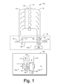
- Fig. 1 is a diagram of a turbocharger and an internal combustion engine
- Fig. 2 is a cross-sectional view of a turbine assembly that includes adjustable vanes to direct exhaust to a turbine wheel;
- Fig. 3 is a series of perspective views of a vane with multiple airfoils
- Fig. 4 is a perspective view of a portion of a variable nozzle turbine assembly that includes a plurality of multiple airfoil vanes;
- Fig. 5 is a series of views of a vane that includes multiple airfoils
- Fig. 6 is a series of views of a vane that includes multiple airfoils
- Fig. 7 is a series of views of a vane that includes multiple airfoils.
- Fig. 8 is a series of views of a vane that includes multiple airfoils with multiple intra-vane throats.
- Vane design in a variable nozzle turbine relates to performance, wear and durability of a turbocharger.
- Vane airfoil characteristics determine, in part, torque generated about a vane's control axle as well as shock and wake created, which impacts turbine wheel performance and reliability.
- certain characteristics benefit torque reduction and certain characteristics benefit wake reduction.
- vanes are presented that have beneficial characteristics.
- various vanes presented herein include multiple airfoils.
- Such multiple airfoil vanes allow for interactions between airfoils, which enable smoother flows that can increase efficiency while minimizing shock/wake. For example, it is desirable to reduce vane trailing edge wake and shock intensity of rotor stator interaction thereby reducing unsteady turbine blade loading while meeting any required torque characteristics (e.g., no directional reversal and lower actuation force).
- Vanes with multiple and differently shaped airfoils also enable torque of a vane to be tuned.
- a conventional system 100 includes an internal combustion engine 110 and a turbocharger 120.
- the internal combustion engine 110 includes an engine block 118 housing one or more combustion chambers that operatively drive a shaft 112.
- an intake port 114 provides a flow path for air to the engine block 118 while an exhaust port 116 provides a flow path for exhaust from the engine block 118.
- the turbocharger 120 acts to extract energy from the exhaust and to provide energy to intake air, which may be combined with fuel to form combustion gas.
- the turbocharger 120 includes an air inlet 134, a shaft 122, a compressor 124, a turbine 126, a housing 128 and an exhaust outlet 136.
- the housing 128 may be referred to as a center housing as it is disposed between the compressor 124 and the turbine 126.
- the shaft 122 may be a shaft assembly that includes a variety of components.
- Such a turbocharger may include one or more variable geometry units, which may use multiple adjustable vanes, an adjustable diffuser section, a wastegate or other features to control the flow of exhaust (e.g., Variable geometry turbine) or to control the flow of intake air (e.g., variable geometry compressor).
- the turbocharger 120 further includes a variable geometry mechanism 130 and an actuator or controller 132.
- the variable geometry mechanism 130 provides for adjusting or altering flow of exhaust to the turbine 126.
- Adjustable vanes positioned at an inlet to a turbine can operate to control flow of exhaust to the turbine.
- GARRETT® VNT® turbochargers adjust the exhaust flow at the inlet of a turbine in order to optimize turbine power with the required load. Movement of vanes towards a closed position typically directs exhaust flow more tangentially to the turbine, which, in turn, imparts more energy to the turbine and, consequently, increases compressor boost. Conversely, movement of vanes towards an open position typically directs exhaust flow in more radially to the turbine, which, in turn, reduces energy to the turbine and, consequently, decreases compressor boost. Closing vanes also restrict the passage there through which creates an increased pressure differential across the turbine, which in turn imparts more energy on the turbine.
- a VGT turbocharger may increase turbine power and boost pressure; whereas, at full engine speed/load and high gas flow, a VGT turbocharger may help avoid turbocharger overspeed and help maintain a suitable or a required boost pressure.
- a variety of control schemes exist for controlling geometry for example, an actuator tied to compressor pressure may control geometry and/or an engine management system may control geometry using a vacuum actuator.
- a VGT may allow for boost pressure regulation which may effectively optimize power output, fuel efficiency, emissions, response, wear, etc.
- a turbocharger may employ wastegate technology as an alternative or in addition to aforementioned variable geometry technologies.
- Fig. 2 shows a cross-sectional view of a turbine assembly 200 having a turbine wheel 204 and vanes (see, e.g., the vane 220) associated with a variable geometry mechanism.
- the turbine assembly 200 may be part of a turbocharger such as the turbocharger 120 of Fig. 1 .
- the turbine wheel 204 includes a plurality of blades (see, e.g., the blade 206) that extend primarily in a radial direction outward from the z-axis.
- the blade 206 which is representative of other blades, has an outer edge 208 where any point thereon can be defined in an r, ⁇ , z coordinate system (i.e., a cylindrical coordinate system).
- the outer edge 208 defines an exducer portion (where exhaust exits) and an inducer portion (where exhaust enters).
- the vane 220 directs exhaust to the inducer portion of the turbine wheel 204.
- the vane 220 is positioned on an axle or post 224, which is set in a vane base 240, which may be part of a variable geometry mechanism.
- the post 224 is aligned substantially parallel with the z-axis of the turbine wheel 204 and includes an upper surface 226. While the post 224 is shown as not extending beyond the upper surface 226, in other examples, a post may be flush with the upper surface 226 or extend above the upper surface 226 (e.g., received by a receptacle of the housing 250, etc.).
- a variable geometry mechanism can provide for rotatable adjustment of the vane 220 along with other vanes to alter exhaust flow to the blades of the turbine wheel 204.
- an adjustment adjusts an entire vane and typically all of the vanes where adjustment of any vane also changes the shape of the flow space between adjacent vanes (e.g., vane throats or nozzles).
- arrows indicate general direction of exhaust flow from an inlet end 223 to an outlet end 225 of the vane 220.
- the turbine assembly 200 is a particular example; noting that various vanes described herein may be implemented in other types of turbine assemblies.
- the assembly 200 has an insert 250 that includes, from the top down (i.e., along the z-axis): a substantially cylindrical or tubular portion 251; a substantially planar, annular portion 253; one or more extensions 255; a leg or step portion 257; and a base portion 259.
- the base portion 259 extends to an opening configured for receipt of a bolt 272 to attach the insert 250 to a center housing 270. As shown in Fig.
- a turbine housing 260 seats over the insert 250 and forms a volute 262, defined at least in part by a volute side surface 264 of the housing 260 and a volute side surface 256 of the inset 250.
- the volute 262 receives exhaust (e.g., from one or more cylinders of an engine) and directs the exhaust to the vanes.
- forces acting on a vane may affect operability or longevity. Such forces may be from flow of exhaust past surfaces of a vane, pressure differentials (e.g., between a command space 245 and vane space), or one or more other factors.
- the controller 132 of Fig. 1 may be in communication with an engine control unit (ECU) that includes a processor and memory.
- the ECU may provide the controller 132 with any of a variety of information (e.g., instructions, throttle, engine speed, etc.) and the controller 132 may likewise provide the ECU with information (e.g., vane position, etc.).
- the controller 132 may be programmed by the ECU or by other techniques.
- the controller 132 may include a processor and memory, optionally as a single integrated circuit (e.g., a chip) or as more than one integrated circuit (e.g., a chipset).
- FIG. 3 shows an example of a vane 300 with multiple airfoils 301 and 303 along with a coordinate system (x, y, z).
- the airfoil 301 is shorter than the airfoil 303 (e.g., along the x-axis).
- the airfoil 301 has an outer facing airfoil surface 312 and an inner facing airfoil surface 314 where the surfaces 312 and 314 are disposed between a leading edge 311, a trailing edge 313, a base surface 322 and a hub surface 324.
- the airfoil 303 has an inner facing airfoil surface 316 and an outer facing airfoil surface 318 where the surfaces 316 and 318 are disposed between a leading edge 315, a trailing edge 317, a base surface 322 and a hub surface 324. Accordingly, in the example of Fig. 3 , the two airfoils 301 and 303 share a common base surface 322 and a common hub surface 324.
- the airfoil surfaces 312, 314, 316 and 318 can be described with respect to the coordinate system and optionally with respect to projections, for example, in two of the three dimensions.
- the vane 300 further includes a post 330 that extends axially downwardly (z-axis) from the base surface 322 to a base end 331 and axially upwardly from the hub surface 324 to a hub end 339.
- the post 330 includes various cylindrical surfaces 332, 334, 336 and 338, which may optionally be defined by a radius or radii about the z-axis.
- a vane may or may not have both an upwardly extending post portion and a downwardly extending post portion.
- other mechanisms exist for adjusting a vane or vanes in a variable nozzle turbine assembly.
- Arrows indicate approximate directions of exhaust flow through a throat defined by the airfoil 301 and 303. As shown, exhaust enters the throat between the leading edges 311 and 315 and exits the throat between the trailing edge 313 of the airfoil 301 and a line or curve along the inner facing surface 316 of the airfoil 303 (e.g., consider a projection of the vane 300 in the x,z-plane).
- the vane 300 includes a first airfoil 301 that includes a length between a leading edge 311 and a trailing edge 313; a second airfoil 303 that includes a length between a leading edge 315 and a trailing edge 317 (e.g., where the length of the first airfoil may differ from the length of the second airfoil); and an intra-vane throat defined at least in part by the first airfoil 301 and the second airfoil 303.
- Fig. 4 shows an example of a portion 400 of a variable nozzle turbine assembly.
- the portion 400 includes four vanes such as the vane 300. Trailing edges of a longer airfoil define a series of vane-to-vane throats 305.
- the variable nozzle turbine assembly includes one intra-vane throat per vane and one inter-vane throat per vane (e.g., as defined between adjacent vanes).
- the portion 400 is shown with respect to a cylindrical coordinate system (r, ⁇ , Z) where the Z-axis is aligned with a rotational axis of a turbine wheel (Z wheel ).
- Each of the vanes 300 is set at a vane radius r V and the vanes are separated at an angle ⁇ .
- a trailing edge radius r TE of each vane 300 changes. Accordingly, each vane can be described with respect to a Cartesian coordinate system (x, y, z) and vanes in a variable nozzle turbine assembly can be further described with respect to a cylindrical coordinate system (r, ⁇ , Z).
- a variable nozzle turbine assembly can include a plurality of vanes that define inter-vane throats where each vane includes a first airfoil that includes a length between a leading edge and a trailing edge; a second airfoil that includes a length between a leading edge and a trailing edge (e.g., where the length of the first airfoil optionally differs from the length of the second airfoil); and one or more intra-vane throats defined at least in part by the first airfoil and the second airfoil.
- each vane includes an axel set in an annular ring.
- a turbine wheel may be provided with characteristics that differ from a conventional turbine wheel (e.g., consider a conventional wheel designed to withstand shock).
- a turbine wheel may be provided that has thinner blades, which can improve efficiency.
- an assembly includes a turbine wheel with blade thickness less than a conventional turbine wheel where the thinner blades are acceptable due to improved shock/wake of multiple airfoil vanes.
- thinner blades allow a turbine wheel to be more efficient than conventional variable nozzle turbine wheels (e.g., consider the blade 206 of Fig. 2 with a thickness less than that of a conventional wheel).
- Fig. 5 shows an example of a vane 500 with multiple airfoils in a series of planar views (i.e., projections in a Cartesian coordinate x, y, z system).
- the vane 500 includes a post 530 that extends from a base end 531 to a hub end 539 with a lower portion 534 and an upper portion 538.
- the following features of the airfoils 501 and 503 are shown: leading edges 511 and 515, trailing edges 513 and 517, hub end surface 524 and post end 539.
- the intra-vane throat outlet is shown as a substantially rectangular shape having an aspect ratio of about 4:1 (i.e., longer along the z-axis than the y-axis).
- the inlet of the intra-vane throat is defined between the leading edges 511 and 515 and has an aspect ratio of about 1:1.5 (i.e., longer along the y-axis that the z-axis). Accordingly, the throat narrows along its y-dimension from the leading edges 511 and 515 to the trailing edge 513.
- the y,z-projection also exhibits edges 535 of the lower post portion 534 and the upper post portion 538, respectively.
- the position of the airfoils 501 and 503 with respect to the post portions 534 and 538 allows for essentially unimpeded along the outer facing surface 518 of the airfoil 503.
- a line drawn between a peak point near the leading edge 515 and the trailing edge 517 shows concavity of the airfoil surface 518; noting that the outer facing airfoil surface of the airfoil 501 is also concave.
- the inner facing airfoil surfaces 514 and 516 both have convexity in the x,y-projection.
- an airfoil may have convexity, concavity or a combination of both in a z,y-projection (e.g., to shape the intra-vane throat exit, the intra-vane throat entrance or points therebetween).
- the vane 500 includes a first airfoil 501 that includes a length between a leading edge 511 and a trailing edge 513; a second airfoil 503 that includes a length between a leading edge 515 and a trailing edge 517 (e.g., where the length of the first airfoil may differ from the length of the second airfoil); and an intra-vane throat defined at least in part by the first airfoil 501 and the second airfoil 503.
- the vane 500 includes a post with a post axis. As described herein, one of the airfoils may be offset from the post axis while the other airfoil may optionally be centered on the post axis.
- Fig. 6 shows an example of a vane 600 with multiple airfoils 601 and 603.
- the vane 600 has a post 630 with a lower portion 634 and an upper portion 638 disposed between a base end 631 and a hub end 639.
- the vane 600 further includes a lower cylindrical plate 623 and an upper cylindrical plate 625.
- the airfoils 601 and 603 may be selected and affixed to the plates 623 and 625. Accordingly, generic post and supports may be provided for use with a variety of different airfoils. Alternatively, a vane may be cast as a single piece. In the example of Fig.
- the airfoil 601 has airfoil surfaces 612 and 614 disposed between a leading edge 611 and a trailing edge 613 and the airfoil 603 has airfoil surfaces 616 and 618 disposed between a leading edge 615 and a trailing edge 617.
- the vane 600 includes a first airfoil 601 that includes a length between a leading edge 611 and a trailing edge 613; a second airfoil 603 that includes a length between a leading edge 615 and a trailing edge 617 (e.g., where the length of the first airfoil may differ from the length of the second airfoil); and an intra-vane throat defined at least in part by the first airfoil 601 and the second airfoil 603.
- Fig. 7 shows an example of a vane 700 with multiple airfoils 701 and 703.
- the vane 700 has a post 730 with a lower portion 734 and an upper portion 738 disposed between a base end 731 and a hub end 739.
- the vane 700 has a "box" shape formed in part by a lower 722 and an upper plate 724.
- the vane 700 may be cast as a single piece or otherwise formed or assembled.
- the airfoil 701 has airfoil surfaces 712 and 714 disposed between a leading edge 711 and a trailing edge 713 and the airfoil 703 has airfoil surfaces 716 and 718 disposed between a leading edge 715 and a trailing edge 717.
- Inner facing surfaces of the lower plate 722 and the upper plate 724 may optionally be shaped to enhance performance.
- the vane 700 includes a first airfoil 701 that includes a length between a leading edge 711 and a trailing edge 713; a second airfoil 703 that includes a length between a leading edge 715 and a trailing edge 717 (e.g., where the length of the first airfoil may differ from the length of the second airfoil); and an intra-vane throat defined at least in part by the first airfoil 701 and the second airfoil 703.
- Fig. 8 shows an example of a vane 800 with multiple airfoils 801 and 803.
- the vane 800 has a post 830 with a lower portion 834 and an upper portion 838 disposed between a base end 831 and a hub end 839.
- the vane 800 has a connector 826 that extends between the two airfoils 801 and 803.
- the vane 800 may be cast as a single piece or otherwise formed or assembled. In the example of Fig.
- the airfoil 801 has airfoil surfaces 812 and 814 disposed between a leading edge 811 and a trailing edge 813 and the airfoil 803 has airfoil surfaces 816 and 818 disposed between a leading edge 815 and a trailing edge 817.
- Surfaces of the connector 826 may optionally be shaped to enhance performance.
- the vane 800 has two intra-vane throats, a hub side throat and a base side throat. While the intra-vane throats are shown as being essentially mirror images of each other, a vane with two airfoils and a connector may have throats that differ. For example, a lower throat may be shaped to enhance flow to a lower inducer portion of a turbine wheel while an upper throat may be shaped to enhance flow to an upper inducer portion of a turbine wheel. Further, while the example of Fig. 8 shows the connector 826 as being essentially planar and at a constant z position along the length of the vane 800, such a connector may optionally be shaped differently (e.g., to provide certain characteristics).
- the vane 800 includes a first airfoil 801 that includes a length between a leading edge 811 and a trailing edge 813; a second airfoil 803 that includes a length between a leading edge 815 and a trailing edge 817 (e.g., where the length of the first airfoil may differ from the length of the second airfoil); and multiple intra-vane throats defined at least in part by the first airfoil 801 and the second airfoil 803.
- one or more airfoils of a multiple airfoil vane may include a non-zero sweep angle, a non-zero lean angle, a non-zero twist angle or any combination thereof (e.g., to provide 3D variation of an airfoil along a z-axis).
- one or more airfoils of a multiple airfoil vane may include 3D variations (e.g., length, width, etc.).
- one or more airfoils of a multiple airfoil vane may include multiple anti-nodes along a camberline (e.g., consider an airfoil with three anti-nodes along a camberline).
- a method can include providing a plurality of multiple airfoil vanes where each vane includes at least one intra-vane throat and where adjacent vanes define inter-vane throats; and pivotably adjusting the plurality of vanes to alter only shape of the inter-vane throats.
- closing the inter-vane throats by pivotably adjusting the plurality of vanes may effectively close the intra-vane throats.
- Such a method may further include providing a turbine wheel with improved efficiency, the improved efficiency resulting from turbine wheel blades configured for flow dynamics associated with the multiple airfoil vanes (e.g., where the vanes improve shock/wake characteristics of flow and allow for blades of lesser mass, thickness, etc.).
Landscapes
- Engineering & Computer Science (AREA)
- Mechanical Engineering (AREA)
- General Engineering & Computer Science (AREA)
- Physics & Mathematics (AREA)
- Fluid Mechanics (AREA)
- Supercharger (AREA)
- Turbine Rotor Nozzle Sealing (AREA)
- Control Of Turbines (AREA)
Applications Claiming Priority (1)
| Application Number | Priority Date | Filing Date | Title |
|---|---|---|---|
| US12/819,218 US8172508B2 (en) | 2010-06-20 | 2010-06-20 | Multiple airfoil vanes |
Publications (3)
| Publication Number | Publication Date |
|---|---|
| EP2397652A2 true EP2397652A2 (de) | 2011-12-21 |
| EP2397652A3 EP2397652A3 (de) | 2014-12-17 |
| EP2397652B1 EP2397652B1 (de) | 2018-08-22 |
Family
ID=44352254
Family Applications (1)
| Application Number | Title | Priority Date | Filing Date |
|---|---|---|---|
| EP11170422.7A Not-in-force EP2397652B1 (de) | 2010-06-20 | 2011-06-17 | Leitschaufel eines Abgasturboladers mit einer Vielzahl von Tragflächen |
Country Status (3)
| Country | Link |
|---|---|
| US (1) | US8172508B2 (de) |
| EP (1) | EP2397652B1 (de) |
| CN (1) | CN102296992B (de) |
Cited By (3)
| Publication number | Priority date | Publication date | Assignee | Title |
|---|---|---|---|---|
| WO2014044364A1 (de) * | 2012-09-24 | 2014-03-27 | Ihi Charging Systems International Gmbh | Verstellbarer leitapparat für einen abgasturbolader und zugehöriger abgasturbolader |
| WO2014072022A1 (de) * | 2012-11-07 | 2014-05-15 | Ihi Charging Systems International Gmbh | Verstellbarer leitapparat für einen abgasführungsabschnitt einer turbine |
| WO2017008683A1 (en) * | 2015-07-10 | 2017-01-19 | Kangyue Technology Co., Ltd | Balanced vanes and integrated actuation system for a variable geometry turbocharger |
Families Citing this family (10)
| Publication number | Priority date | Publication date | Assignee | Title |
|---|---|---|---|---|
| DE102008058014A1 (de) * | 2008-11-19 | 2010-05-20 | Rolls-Royce Deutschland Ltd & Co Kg | Mehrschaufelige Verstellstatoreinheit einer Strömungsarbeitsmaschine |
| KR101959315B1 (ko) * | 2012-01-13 | 2019-07-02 | 보르그워너 인코퍼레이티드 | 홈이 형성된 가이드 베인을 가진 가변 터빈 구조를 구비한 터보차저 |
| US9057280B2 (en) * | 2012-01-31 | 2015-06-16 | Honeywell International Inc. | Contacting vanes |
| USD748054S1 (en) * | 2013-02-19 | 2016-01-26 | Tnp Co., Ltd. | Wind turbine blade |
| GB2533351A (en) * | 2014-12-17 | 2016-06-22 | Gm Global Tech Operations Inc | Internal combustion engine having a two stage turbocharger |
| DE102015205208A1 (de) * | 2015-03-23 | 2016-09-29 | Bosch Mahle Turbo Systems Gmbh & Co. Kg | Ladeeinrichtung mit variabler Turbinengeometrie |
| US10253648B2 (en) | 2016-03-04 | 2019-04-09 | General Electric Company | Modulated hybrid variable area turbine nozzle for gas turbine engine |
| DE102018211673A1 (de) * | 2018-07-12 | 2020-01-16 | Continental Automotive Gmbh | Leitschaufel und mit einer solchen versehene Turbinenanordnung |
| DE102019127980A1 (de) * | 2019-10-16 | 2021-04-22 | Ihi Charging Systems International Gmbh | Verstellbarer Leitapparat für einen Abgasführungsabschnitt eines Abgasturboladers und Abgasturbolader |
| CN113513368B (zh) * | 2021-07-08 | 2022-09-02 | 哈尔滨工程大学 | 一种带有子母动叶片结构的可直接倒车涡轮 |
Family Cites Families (18)
| Publication number | Priority date | Publication date | Assignee | Title |
|---|---|---|---|---|
| CH390948A (de) * | 1961-01-24 | 1965-04-30 | Kuehnle Kopp Kausch Ag | Gasturbine |
| US3069070A (en) * | 1961-11-14 | 1962-12-18 | Worthington Corp | Diffuser vane system for turbomachinery |
| FR1405388A (fr) * | 1964-05-14 | 1965-07-09 | Hispano Suiza Sa | Perfectionnements apportés aux compresseurs supersoniques, notamment à ceux du type centrifuge ou axial-centrifuge |
| CH492130A (de) * | 1968-08-20 | 1970-06-15 | Escher Wyss Ag | Das Laufrad eines Zentrifugalverdichters koaxial umschliessender, für die Anströmung mit Überschallgeschwindigkeit bestimmter Leitapparat |
| FR2093363A5 (de) * | 1970-06-12 | 1972-01-28 | Neyrpic | |
| US3957392A (en) * | 1974-11-01 | 1976-05-18 | Caterpillar Tractor Co. | Self-aligning vanes for a turbomachine |
| DE3542762A1 (de) * | 1985-12-04 | 1987-06-11 | Mtu Muenchen Gmbh | Einrichtung zur steuerung oder regelung von gasturbinentriebwerken bzw. gasturbinenstrahltriebwerken |
| DE19752534C1 (de) | 1997-11-27 | 1998-10-08 | Daimler Benz Ag | Radialdurchströmte Abgasturboladerturbine |
| WO2003074850A1 (en) * | 2002-03-01 | 2003-09-12 | Honeywell International Inc. | Improved vane design for use in variable geometry_turbocharger |
| US6709232B1 (en) | 2002-09-05 | 2004-03-23 | Honeywell International Inc. | Cambered vane for use in turbochargers |
| US6948907B2 (en) | 2003-05-05 | 2005-09-27 | Honeywell International, Inc. | Vane and/or blade for noise control |
| US7147433B2 (en) | 2003-11-19 | 2006-12-12 | Honeywell International, Inc. | Profiled blades for turbocharger turbines, compressors, and the like |
| US7255530B2 (en) | 2003-12-12 | 2007-08-14 | Honeywell International Inc. | Vane and throat shaping |
| AU2003300242A1 (en) * | 2003-12-31 | 2005-07-21 | Honeywell International, Inc. | Cambered vane for use in turbochargers |
| EP1790830B1 (de) | 2005-11-25 | 2019-03-27 | BorgWarner, Inc. | Schaufel eines Turboladers, sowie Turbolader |
| EP2092163A4 (de) * | 2006-11-14 | 2013-04-17 | Volvo Aero Corp | Leitschaufelanordnung, die zum drehen eines stroms in einem gasturbinentriebwerk konfiguriert ist, statorkomponente mit der leitschaufelanordnung, gasturbine und flugzeugstrahltriebwerk |
| DE102007060044A1 (de) * | 2007-12-13 | 2009-06-18 | Bosch Mahle Turbo Systems Gmbh & Co. Kg | Variable Turbinengeometrie |
| DE102008058014A1 (de) * | 2008-11-19 | 2010-05-20 | Rolls-Royce Deutschland Ltd & Co Kg | Mehrschaufelige Verstellstatoreinheit einer Strömungsarbeitsmaschine |
-
2010
- 2010-06-20 US US12/819,218 patent/US8172508B2/en not_active Expired - Fee Related
-
2011
- 2011-06-17 EP EP11170422.7A patent/EP2397652B1/de not_active Not-in-force
- 2011-06-20 CN CN201110222934.6A patent/CN102296992B/zh not_active Expired - Fee Related
Non-Patent Citations (1)
| Title |
|---|
| None |
Cited By (3)
| Publication number | Priority date | Publication date | Assignee | Title |
|---|---|---|---|---|
| WO2014044364A1 (de) * | 2012-09-24 | 2014-03-27 | Ihi Charging Systems International Gmbh | Verstellbarer leitapparat für einen abgasturbolader und zugehöriger abgasturbolader |
| WO2014072022A1 (de) * | 2012-11-07 | 2014-05-15 | Ihi Charging Systems International Gmbh | Verstellbarer leitapparat für einen abgasführungsabschnitt einer turbine |
| WO2017008683A1 (en) * | 2015-07-10 | 2017-01-19 | Kangyue Technology Co., Ltd | Balanced vanes and integrated actuation system for a variable geometry turbocharger |
Also Published As
| Publication number | Publication date |
|---|---|
| EP2397652A3 (de) | 2014-12-17 |
| US8172508B2 (en) | 2012-05-08 |
| CN102296992B (zh) | 2015-09-23 |
| US20110312246A1 (en) | 2011-12-22 |
| EP2397652B1 (de) | 2018-08-22 |
| CN102296992A (zh) | 2011-12-28 |
Similar Documents
| Publication | Publication Date | Title |
|---|---|---|
| US8172508B2 (en) | Multiple airfoil vanes | |
| US8834104B2 (en) | Vanes for directing exhaust to a turbine wheel | |
| US8360730B2 (en) | Turbine wheel with backswept inducer | |
| EP2525101B1 (de) | Verteilungstrenner | |
| US7255530B2 (en) | Vane and throat shaping | |
| CN104838109B (zh) | 具有单阀的混合流动双涡旋涡轮增压器 | |
| US9567942B1 (en) | Centrifugal turbomachines having extended performance ranges | |
| CN103180569A (zh) | 具有增加的流量范围的简化型可变几何形状涡轮增压器 | |
| US10392961B2 (en) | Nozzle blade design for a variable nozzle turbine | |
| US6948907B2 (en) | Vane and/or blade for noise control | |
| EP2749738B1 (de) | Abgasturboladeranordnung sowie Abgasturbolader | |
| JP2011111988A (ja) | 過給エンジンシステム | |
| EP1794416B1 (de) | Turbine mit variabler geometrie mit druckausgeglichenen schaufeln sowie verfahren zum betrieb | |
| US9057280B2 (en) | Contacting vanes |
Legal Events
| Date | Code | Title | Description |
|---|---|---|---|
| 17P | Request for examination filed |
Effective date: 20110617 |
|
| AK | Designated contracting states |
Kind code of ref document: A2 Designated state(s): AL AT BE BG CH CY CZ DE DK EE ES FI FR GB GR HR HU IE IS IT LI LT LU LV MC MK MT NL NO PL PT RO RS SE SI SK SM TR |
|
| AX | Request for extension of the european patent |
Extension state: BA ME |
|
| PUAI | Public reference made under article 153(3) epc to a published international application that has entered the european phase |
Free format text: ORIGINAL CODE: 0009012 |
|
| PUAL | Search report despatched |
Free format text: ORIGINAL CODE: 0009013 |
|
| AK | Designated contracting states |
Kind code of ref document: A3 Designated state(s): AL AT BE BG CH CY CZ DE DK EE ES FI FR GB GR HR HU IE IS IT LI LT LU LV MC MK MT NL NO PL PT RO RS SE SI SK SM TR |
|
| AX | Request for extension of the european patent |
Extension state: BA ME |
|
| RIC1 | Information provided on ipc code assigned before grant |
Ipc: F01D 5/14 20060101AFI20141107BHEP Ipc: F01D 17/16 20060101ALI20141107BHEP |
|
| 17Q | First examination report despatched |
Effective date: 20141121 |
|
| RAP1 | Party data changed (applicant data changed or rights of an application transferred) |
Owner name: HONEYWELL INTERNATIONAL INC. |
|
| STAA | Information on the status of an ep patent application or granted ep patent |
Free format text: STATUS: EXAMINATION IS IN PROGRESS |
|
| GRAP | Despatch of communication of intention to grant a patent |
Free format text: ORIGINAL CODE: EPIDOSNIGR1 |
|
| STAA | Information on the status of an ep patent application or granted ep patent |
Free format text: STATUS: GRANT OF PATENT IS INTENDED |
|
| INTG | Intention to grant announced |
Effective date: 20180315 |
|
| GRAS | Grant fee paid |
Free format text: ORIGINAL CODE: EPIDOSNIGR3 |
|
| GRAA | (expected) grant |
Free format text: ORIGINAL CODE: 0009210 |
|
| STAA | Information on the status of an ep patent application or granted ep patent |
Free format text: STATUS: THE PATENT HAS BEEN GRANTED |
|
| AK | Designated contracting states |
Kind code of ref document: B1 Designated state(s): AL AT BE BG CH CY CZ DE DK EE ES FI FR GB GR HR HU IE IS IT LI LT LU LV MC MK MT NL NO PL PT RO RS SE SI SK SM TR |
|
| REG | Reference to a national code |
Ref country code: GB Ref legal event code: FG4D |
|
| REG | Reference to a national code |
Ref country code: CH Ref legal event code: EP |
|
| REG | Reference to a national code |
Ref country code: DE Ref legal event code: R096 Ref document number: 602011051235 Country of ref document: DE |
|
| REG | Reference to a national code |
Ref country code: AT Ref legal event code: REF Ref document number: 1032763 Country of ref document: AT Kind code of ref document: T Effective date: 20180915 |
|
| REG | Reference to a national code |
Ref country code: IE Ref legal event code: FG4D |
|
| REG | Reference to a national code |
Ref country code: NL Ref legal event code: MP Effective date: 20180822 |
|
| REG | Reference to a national code |
Ref country code: LT Ref legal event code: MG4D |
|
| PG25 | Lapsed in a contracting state [announced via postgrant information from national office to epo] |
Ref country code: GR Free format text: LAPSE BECAUSE OF FAILURE TO SUBMIT A TRANSLATION OF THE DESCRIPTION OR TO PAY THE FEE WITHIN THE PRESCRIBED TIME-LIMIT Effective date: 20181123 Ref country code: FI Free format text: LAPSE BECAUSE OF FAILURE TO SUBMIT A TRANSLATION OF THE DESCRIPTION OR TO PAY THE FEE WITHIN THE PRESCRIBED TIME-LIMIT Effective date: 20180822 Ref country code: SE Free format text: LAPSE BECAUSE OF FAILURE TO SUBMIT A TRANSLATION OF THE DESCRIPTION OR TO PAY THE FEE WITHIN THE PRESCRIBED TIME-LIMIT Effective date: 20180822 Ref country code: RS Free format text: LAPSE BECAUSE OF FAILURE TO SUBMIT A TRANSLATION OF THE DESCRIPTION OR TO PAY THE FEE WITHIN THE PRESCRIBED TIME-LIMIT Effective date: 20180822 Ref country code: IS Free format text: LAPSE BECAUSE OF FAILURE TO SUBMIT A TRANSLATION OF THE DESCRIPTION OR TO PAY THE FEE WITHIN THE PRESCRIBED TIME-LIMIT Effective date: 20181222 Ref country code: LT Free format text: LAPSE BECAUSE OF FAILURE TO SUBMIT A TRANSLATION OF THE DESCRIPTION OR TO PAY THE FEE WITHIN THE PRESCRIBED TIME-LIMIT Effective date: 20180822 Ref country code: NO Free format text: LAPSE BECAUSE OF FAILURE TO SUBMIT A TRANSLATION OF THE DESCRIPTION OR TO PAY THE FEE WITHIN THE PRESCRIBED TIME-LIMIT Effective date: 20181122 Ref country code: BG Free format text: LAPSE BECAUSE OF FAILURE TO SUBMIT A TRANSLATION OF THE DESCRIPTION OR TO PAY THE FEE WITHIN THE PRESCRIBED TIME-LIMIT Effective date: 20181122 Ref country code: NL Free format text: LAPSE BECAUSE OF FAILURE TO SUBMIT A TRANSLATION OF THE DESCRIPTION OR TO PAY THE FEE WITHIN THE PRESCRIBED TIME-LIMIT Effective date: 20180822 |
|
| REG | Reference to a national code |
Ref country code: AT Ref legal event code: MK05 Ref document number: 1032763 Country of ref document: AT Kind code of ref document: T Effective date: 20180822 |
|
| PG25 | Lapsed in a contracting state [announced via postgrant information from national office to epo] |
Ref country code: AL Free format text: LAPSE BECAUSE OF FAILURE TO SUBMIT A TRANSLATION OF THE DESCRIPTION OR TO PAY THE FEE WITHIN THE PRESCRIBED TIME-LIMIT Effective date: 20180822 Ref country code: ES Free format text: LAPSE BECAUSE OF FAILURE TO SUBMIT A TRANSLATION OF THE DESCRIPTION OR TO PAY THE FEE WITHIN THE PRESCRIBED TIME-LIMIT Effective date: 20180822 Ref country code: HR Free format text: LAPSE BECAUSE OF FAILURE TO SUBMIT A TRANSLATION OF THE DESCRIPTION OR TO PAY THE FEE WITHIN THE PRESCRIBED TIME-LIMIT Effective date: 20180822 Ref country code: LV Free format text: LAPSE BECAUSE OF FAILURE TO SUBMIT A TRANSLATION OF THE DESCRIPTION OR TO PAY THE FEE WITHIN THE PRESCRIBED TIME-LIMIT Effective date: 20180822 |
|
| PG25 | Lapsed in a contracting state [announced via postgrant information from national office to epo] |
Ref country code: AT Free format text: LAPSE BECAUSE OF FAILURE TO SUBMIT A TRANSLATION OF THE DESCRIPTION OR TO PAY THE FEE WITHIN THE PRESCRIBED TIME-LIMIT Effective date: 20180822 Ref country code: EE Free format text: LAPSE BECAUSE OF FAILURE TO SUBMIT A TRANSLATION OF THE DESCRIPTION OR TO PAY THE FEE WITHIN THE PRESCRIBED TIME-LIMIT Effective date: 20180822 Ref country code: PL Free format text: LAPSE BECAUSE OF FAILURE TO SUBMIT A TRANSLATION OF THE DESCRIPTION OR TO PAY THE FEE WITHIN THE PRESCRIBED TIME-LIMIT Effective date: 20180822 Ref country code: CZ Free format text: LAPSE BECAUSE OF FAILURE TO SUBMIT A TRANSLATION OF THE DESCRIPTION OR TO PAY THE FEE WITHIN THE PRESCRIBED TIME-LIMIT Effective date: 20180822 Ref country code: RO Free format text: LAPSE BECAUSE OF FAILURE TO SUBMIT A TRANSLATION OF THE DESCRIPTION OR TO PAY THE FEE WITHIN THE PRESCRIBED TIME-LIMIT Effective date: 20180822 Ref country code: IT Free format text: LAPSE BECAUSE OF FAILURE TO SUBMIT A TRANSLATION OF THE DESCRIPTION OR TO PAY THE FEE WITHIN THE PRESCRIBED TIME-LIMIT Effective date: 20180822 |
|
| RAP2 | Party data changed (patent owner data changed or rights of a patent transferred) |
Owner name: GARRETT TRANSPORTATION I INC. |
|
| REG | Reference to a national code |
Ref country code: DE Ref legal event code: R097 Ref document number: 602011051235 Country of ref document: DE |
|
| PG25 | Lapsed in a contracting state [announced via postgrant information from national office to epo] |
Ref country code: SM Free format text: LAPSE BECAUSE OF FAILURE TO SUBMIT A TRANSLATION OF THE DESCRIPTION OR TO PAY THE FEE WITHIN THE PRESCRIBED TIME-LIMIT Effective date: 20180822 Ref country code: DK Free format text: LAPSE BECAUSE OF FAILURE TO SUBMIT A TRANSLATION OF THE DESCRIPTION OR TO PAY THE FEE WITHIN THE PRESCRIBED TIME-LIMIT Effective date: 20180822 Ref country code: SK Free format text: LAPSE BECAUSE OF FAILURE TO SUBMIT A TRANSLATION OF THE DESCRIPTION OR TO PAY THE FEE WITHIN THE PRESCRIBED TIME-LIMIT Effective date: 20180822 |
|
| PLBE | No opposition filed within time limit |
Free format text: ORIGINAL CODE: 0009261 |
|
| STAA | Information on the status of an ep patent application or granted ep patent |
Free format text: STATUS: NO OPPOSITION FILED WITHIN TIME LIMIT |
|
| 26N | No opposition filed |
Effective date: 20190523 |
|
| REG | Reference to a national code |
Ref country code: DE Ref legal event code: R081 Ref document number: 602011051235 Country of ref document: DE Owner name: GARRETT TRANSPORTATION I INC., TORRANCE, US Free format text: FORMER OWNER: HONEYWELL INTERNATIONAL INC., MORRIS PLAINS, N.J., US |
|
| REG | Reference to a national code |
Ref country code: GB Ref legal event code: 732E Free format text: REGISTERED BETWEEN 20190725 AND 20190731 |
|
| PG25 | Lapsed in a contracting state [announced via postgrant information from national office to epo] |
Ref country code: SI Free format text: LAPSE BECAUSE OF FAILURE TO SUBMIT A TRANSLATION OF THE DESCRIPTION OR TO PAY THE FEE WITHIN THE PRESCRIBED TIME-LIMIT Effective date: 20180822 |
|
| PGFP | Annual fee paid to national office [announced via postgrant information from national office to epo] |
Ref country code: FR Payment date: 20190625 Year of fee payment: 9 |
|
| PGFP | Annual fee paid to national office [announced via postgrant information from national office to epo] |
Ref country code: GB Payment date: 20190627 Year of fee payment: 9 Ref country code: DE Payment date: 20190628 Year of fee payment: 9 |
|
| PG25 | Lapsed in a contracting state [announced via postgrant information from national office to epo] |
Ref country code: MC Free format text: LAPSE BECAUSE OF FAILURE TO SUBMIT A TRANSLATION OF THE DESCRIPTION OR TO PAY THE FEE WITHIN THE PRESCRIBED TIME-LIMIT Effective date: 20180822 |
|
| REG | Reference to a national code |
Ref country code: CH Ref legal event code: PL |
|
| REG | Reference to a national code |
Ref country code: BE Ref legal event code: MM Effective date: 20190630 |
|
| PG25 | Lapsed in a contracting state [announced via postgrant information from national office to epo] |
Ref country code: TR Free format text: LAPSE BECAUSE OF FAILURE TO SUBMIT A TRANSLATION OF THE DESCRIPTION OR TO PAY THE FEE WITHIN THE PRESCRIBED TIME-LIMIT Effective date: 20180822 |
|
| PG25 | Lapsed in a contracting state [announced via postgrant information from national office to epo] |
Ref country code: IE Free format text: LAPSE BECAUSE OF NON-PAYMENT OF DUE FEES Effective date: 20190617 |
|
| PG25 | Lapsed in a contracting state [announced via postgrant information from national office to epo] |
Ref country code: LU Free format text: LAPSE BECAUSE OF NON-PAYMENT OF DUE FEES Effective date: 20190617 Ref country code: CH Free format text: LAPSE BECAUSE OF NON-PAYMENT OF DUE FEES Effective date: 20190630 Ref country code: LI Free format text: LAPSE BECAUSE OF NON-PAYMENT OF DUE FEES Effective date: 20190630 Ref country code: BE Free format text: LAPSE BECAUSE OF NON-PAYMENT OF DUE FEES Effective date: 20190630 |
|
| PG25 | Lapsed in a contracting state [announced via postgrant information from national office to epo] |
Ref country code: PT Free format text: LAPSE BECAUSE OF FAILURE TO SUBMIT A TRANSLATION OF THE DESCRIPTION OR TO PAY THE FEE WITHIN THE PRESCRIBED TIME-LIMIT Effective date: 20181222 |
|
| REG | Reference to a national code |
Ref country code: DE Ref legal event code: R119 Ref document number: 602011051235 Country of ref document: DE |
|
| GBPC | Gb: european patent ceased through non-payment of renewal fee |
Effective date: 20200617 |
|
| PG25 | Lapsed in a contracting state [announced via postgrant information from national office to epo] |
Ref country code: FR Free format text: LAPSE BECAUSE OF NON-PAYMENT OF DUE FEES Effective date: 20200630 Ref country code: GB Free format text: LAPSE BECAUSE OF NON-PAYMENT OF DUE FEES Effective date: 20200617 |
|
| PG25 | Lapsed in a contracting state [announced via postgrant information from national office to epo] |
Ref country code: DE Free format text: LAPSE BECAUSE OF NON-PAYMENT OF DUE FEES Effective date: 20210101 Ref country code: CY Free format text: LAPSE BECAUSE OF FAILURE TO SUBMIT A TRANSLATION OF THE DESCRIPTION OR TO PAY THE FEE WITHIN THE PRESCRIBED TIME-LIMIT Effective date: 20180822 |
|
| PG25 | Lapsed in a contracting state [announced via postgrant information from national office to epo] |
Ref country code: HU Free format text: LAPSE BECAUSE OF FAILURE TO SUBMIT A TRANSLATION OF THE DESCRIPTION OR TO PAY THE FEE WITHIN THE PRESCRIBED TIME-LIMIT; INVALID AB INITIO Effective date: 20110617 Ref country code: MT Free format text: LAPSE BECAUSE OF FAILURE TO SUBMIT A TRANSLATION OF THE DESCRIPTION OR TO PAY THE FEE WITHIN THE PRESCRIBED TIME-LIMIT Effective date: 20180822 |
|
| PG25 | Lapsed in a contracting state [announced via postgrant information from national office to epo] |
Ref country code: MK Free format text: LAPSE BECAUSE OF FAILURE TO SUBMIT A TRANSLATION OF THE DESCRIPTION OR TO PAY THE FEE WITHIN THE PRESCRIBED TIME-LIMIT Effective date: 20180822 |