EP2397600B1 - Verfahren zum Messen des Trägheitsmoments einer Trommel einer Waschmaschine und zur Umsetzung dieses Verfahrens eingerichtete Waschmaschine - Google Patents
Verfahren zum Messen des Trägheitsmoments einer Trommel einer Waschmaschine und zur Umsetzung dieses Verfahrens eingerichtete Waschmaschine Download PDFInfo
- Publication number
- EP2397600B1 EP2397600B1 EP11169751A EP11169751A EP2397600B1 EP 2397600 B1 EP2397600 B1 EP 2397600B1 EP 11169751 A EP11169751 A EP 11169751A EP 11169751 A EP11169751 A EP 11169751A EP 2397600 B1 EP2397600 B1 EP 2397600B1
- Authority
- EP
- European Patent Office
- Prior art keywords
- drum
- angular velocity
- electric motor
- value
- synchronous electric
- Prior art date
- Legal status (The legal status is an assumption and is not a legal conclusion. Google has not performed a legal analysis and makes no representation as to the accuracy of the status listed.)
- Active
Links
Images


Classifications
-
- D—TEXTILES; PAPER
- D06—TREATMENT OF TEXTILES OR THE LIKE; LAUNDERING; FLEXIBLE MATERIALS NOT OTHERWISE PROVIDED FOR
- D06F—LAUNDERING, DRYING, IRONING, PRESSING OR FOLDING TEXTILE ARTICLES
- D06F34/00—Details of control systems for washing machines, washer-dryers or laundry dryers
- D06F34/14—Arrangements for detecting or measuring specific parameters
- D06F34/16—Imbalance
-
- D—TEXTILES; PAPER
- D06—TREATMENT OF TEXTILES OR THE LIKE; LAUNDERING; FLEXIBLE MATERIALS NOT OTHERWISE PROVIDED FOR
- D06F—LAUNDERING, DRYING, IRONING, PRESSING OR FOLDING TEXTILE ARTICLES
- D06F34/00—Details of control systems for washing machines, washer-dryers or laundry dryers
- D06F34/14—Arrangements for detecting or measuring specific parameters
- D06F34/18—Condition of the laundry, e.g. nature or weight
-
- D—TEXTILES; PAPER
- D06—TREATMENT OF TEXTILES OR THE LIKE; LAUNDERING; FLEXIBLE MATERIALS NOT OTHERWISE PROVIDED FOR
- D06F—LAUNDERING, DRYING, IRONING, PRESSING OR FOLDING TEXTILE ARTICLES
- D06F2103/00—Parameters monitored or detected for the control of domestic laundry washing machines, washer-dryers or laundry dryers
- D06F2103/24—Spin speed; Drum movements
-
- D—TEXTILES; PAPER
- D06—TREATMENT OF TEXTILES OR THE LIKE; LAUNDERING; FLEXIBLE MATERIALS NOT OTHERWISE PROVIDED FOR
- D06F—LAUNDERING, DRYING, IRONING, PRESSING OR FOLDING TEXTILE ARTICLES
- D06F2103/00—Parameters monitored or detected for the control of domestic laundry washing machines, washer-dryers or laundry dryers
- D06F2103/26—Imbalance; Noise level
-
- D—TEXTILES; PAPER
- D06—TREATMENT OF TEXTILES OR THE LIKE; LAUNDERING; FLEXIBLE MATERIALS NOT OTHERWISE PROVIDED FOR
- D06F—LAUNDERING, DRYING, IRONING, PRESSING OR FOLDING TEXTILE ARTICLES
- D06F2103/00—Parameters monitored or detected for the control of domestic laundry washing machines, washer-dryers or laundry dryers
- D06F2103/38—Time, e.g. duration
-
- D—TEXTILES; PAPER
- D06—TREATMENT OF TEXTILES OR THE LIKE; LAUNDERING; FLEXIBLE MATERIALS NOT OTHERWISE PROVIDED FOR
- D06F—LAUNDERING, DRYING, IRONING, PRESSING OR FOLDING TEXTILE ARTICLES
- D06F2105/00—Systems or parameters controlled or affected by the control systems of washing machines, washer-dryers or laundry dryers
- D06F2105/46—Drum speed; Actuation of motors, e.g. starting or interrupting
- D06F2105/48—Drum speed
Definitions
- the present invention refers, in the most general aspect thereof, to a method for measuring the moment of inertia of a drum of a rotary drum washing machine.
- washing machines laundry machines or similar machines, for household or industrial use, comprising a rotary drum for the introduction of articles to be subjected to washing, drying or centrifuge cycles.
- the machines of the type indicated above are generally referred to by the term washing machines.
- washing machines comprise a drum, rotating within a drum, rotated by an electric motor, which - in most cases - is connected to the drum by means of a transmission drive pulley.
- the user introduces - into said drum - a load represented by the laundry to be washed which, upon reaching a given spin velocity (generally comprised between 80 and 120 revolutions per minute), is pressed substantially uniformly along the peripheral walls of the drum.
- a given spin velocity generally comprised between 80 and 120 revolutions per minute
- the washing and or drying process can be advantageously optimised according to the laundry load contained in the drum, for example adjusting - as a function thereof - some operating parameters such as the water flow and the amount of detergent introduced, the rotation velocity of the drum, the duration of the subsequent washing steps.
- a measurement of the moment of inertia of the loaded drum, performed by the electronic control unit just before the washing and/or drying process, allows obtaining information regarding the introduced load hence allowing the abovementioned process optimization.
- Such method provides for monitoring, by measuring the voltage and current development of a power supply circuit, the instantaneous electrical power absorbed during an acceleration transient of the drum.
- the power absorbed during the transient from which a term regarding the frictions is subtracted to obtain a value substantially proportional to the moment of inertia of the loaded drum, is calculated by integrating such power with respect to time.
- the method provided for requires considerable computational weight, mainly due to the operation of integrating power with respect to time.
- the technical problem on which the present invention is based is that of providing an alternative method for measuring the moment of inertia, capable of overcoming the drawbacks of the prior art.
- the identification - on the torque signal - of a synchronisation point for starting the acceleration transient means starting the transient always at an unbalanced load position known a priori.
- Such solution allows greater measurement accuracy, eliminating the measurement error identified in the known art.
- the method according to the present invention can advantageously be implemented even with relatively short acceleration transients, for example from 90 to 135 revolutions per minute.
- the method subject of the invention can measure the torque delivered by the electric motor at the first angular velocity and that delivered at the second angular velocity.
- an efficient estimation of the torque required to overcome the frictions during the acceleration transient by calculating the average value of the two torques measured at the ends of the transients, can then be performed.
- Said average value can thus be subtracted from the value of the electromotive torque delivered during the acceleration transient to obtain an estimation of the value of torque yielded to the drum.
- the signal of the absorbed quadrature current Iq can advantageously be used as the signal indicative of the torque delivered with respect to that identifying the synchronisation point.
- the synchronisation point can be a peak point (maximum or minimum) of the signal, which can be easily identified by analyzing the derivatives.
- the step of starting an acceleration transient may provide for taking the quadrature current Iq of the motor to a predefined value, which is maintained constant during the entire transient time.
- the torque delivered by a synchronous motor is substantially proportional to the absorbed quadrature current Iq, hence the constant current condition also guarantees a constant torque.
- the step of interrupting the acceleration transient upon reaching a second angular velocity may provide for the periodic acquisition, during the acceleration transient, of an angular velocity of the drum through a position sensor.
- the velocity can be estimated in sensorless mode.
- the synchronous electric motor Upon reaching (detected or estimated) the desired second angular velocity, the synchronous electric motor, initially maintained at constant quadrature current Iq, moves to a feedback control in which it is maintained at angular velocity equivalent to said second angular velocity.
- the step of setting the drum in rotation taking it to a first angular velocity can advantageously provide for a feedback control of the synchronous electric motor.
- the angular velocity thereof, acquired by the position sensor, will then be compared with the desired first angular velocity.
- the velocity can alternatively be estimated in sensorless mode.
- the position sensor used can for example be a Hall effect sensor.
- the torque delivered by the permanent magnet synchronous electric motor is proportional to the product of the quadrature current Iq and the magnetic flux ⁇ linked by the stator magnetic circuit.
- the value of the magnetic flux ⁇ is thus used in the present method to obtain the torque delivered by the synchronous electric motor starting from the value of absorbed quadrature current Iq.
- Such flux is theoretically known given the characteristics of the stator magnetic circuit; practically, it can however diverge from the theoretical value due to the production variability.
- a step for estimating the value of magnetic flux starting from state variables of the motor can be included in the present method with the aim of improving the measurement accuracy.
- the step of estimating the value of the magnetic flux ⁇ can apply an estimation algorithm which uses correction coefficients to compensate the errors made when measuring state variables of the motor and when estimating the operating parameters thereof.
- the estimation algorithm should the present method be implemented without using the position sensor, can also enable the estimation of the velocity of the drum.
- Another error observed when estimating the magnetic flux ⁇ is due to the influence of temperature; such error can be advantageously compensated by acquiring a temperature value of the synchronous electric motor through a heat sensor.
- the step of estimating the magnetic flux ⁇ can advantageously apply a method simplified with respect to the use of the estimation algorithm outlined above.
- the flux can be estimated by correcting a nominal value of magnetic flux ⁇ ref at a reference temperature T ref according to a measured motor temperature T.
- ⁇ ⁇ Re f ⁇ T - T Re f ⁇ 1 - ⁇
- the measured temperature should be greater than the reference temperature, which can for example be 25°C and where ⁇ , thermal coefficient of the magnet, is normally equivalent to 0.002.
- the value of magnetic flux ⁇ can be estimated more accurately considering a correction coefficient k, identifying the construction variability of the motor, measured by way of experiment by operating the motor with known torque in a testing step.
- a washing machine comprising: a rotary drum; a permanent magnet synchronous electric motor for rotating said drum; a control unit connected to said synchronous electric motor; said control unit being provided for implementing the previously described method.
- the washing machine may also comprise a position sensor connected to said control unit to detect an angular position of said drum.
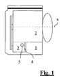
- a washing machine comprising a drum 2, mounted in a housing drum according to a horizontal rotational axis x, and a synchronous electric motor 3 provided for moving the drum 2 around the rotation axis x is generally identified with 1.
- the drum 2 is provided for receiving laundry or other articles to be washed therein; in the rest of the present description such drum content will be generally referred to by the term load.
- the synchronous electric motor 3 is of the permanent magnet type with external cup rotor connected - in a known manner - with a driving belt to the previously identified rotary drums 2.
- the synchronous electric motor 3 is associated to a control unit 4, comprising a motor driving circuit, which has the purpose of executing the method for measuring the moment of inertia described below.
- Said control unit 4 is connected to a Hall effect sensor 5 for detecting the angular velocity of the synchronous electric motor 3.
- the number of poles pp and coils N are construction quantities of the motor known a priori.
- the magnetic flux ⁇ is a quantity known from the morphology of the magnetic circuit, though with inaccuracies due to the production variability and influence of temperature.
- the absorbed current I q obtainable in a known manner starting from the phase currents of the motor by means of the known Park and Clark transformations, can be directly measured and controlled by the control unit 4.
- the control unit 4 is thus capable of evaluating the electromotive torque T em_acc delivered by the motor during the acceleration transient; the yielded torque Tacc, i.e the electromotive torque T em_acc excluding the torque required to overcome the frictions of the rotary system during the acceleration transient, is however required to obtain the moment of inertia J through the formula (4).
- the useful estimation of this variable can be obtained through a simple calculation of the average of the torques detectable at constant angular velocity (and thus entirely caused by the frictions) at the first ⁇ 1 and the second angular velocity ⁇ 2 , i.e. the start and end velocity of the transient.
- J 2 3 ⁇ pp 2 ⁇ ⁇ ⁇ N ⁇ I q_acc - I q_ 1 + I q_ 2 2 ⁇ ⁇ ⁇ t ⁇ ⁇ ⁇
- I q_acc , I q_1 and I q_2 are values of the quadrature current respectively during the acceleration transient, at the first angular velocity ⁇ 1 and at the second angular velocity ⁇ 2 .
- the method which can be advantageously implemented when starting the washing cycle of the washing machine 1, provides for a first step which consists in taking the drum 2 to the first angular velocity ⁇ 1 .
- Such angular velocity should be greater than the load spin velocity; in the present example a value of the first angular velocity ⁇ 1 is considered equivalent to 95 revolutions per minute, assuming that the load is pressed against the drum at 80 revolutions per minute.
- the drum is brought to the first angular velocity ⁇ 1 proceeding in the known manner by operating on the control variables of the electric motor 3 (block 100 of figure 2 ) and by feedback controlling whether the drum 2 has reached the desired velocity (block 101).
- the control unit 4 uses the Hall effect sensor 5 to detect the angular velocity of the rotor.
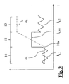
- the drum 2 Upon reaching the first angular velocity ⁇ 1 , the drum 2 rotates at constant velocity during a first stage 10 of measurement cycle.
- control unit 4 acquires said mean value (block 102); such value represents the quadrature current I q_1 at the first angular velocity ⁇ 1 to be used in the equation (6).
- the control unit can evaluate, using the equation (5) described previously, the torque T 1 required from the motor to overcome the frictions of the rotary system at the first angular velocity ⁇ 1 (block 103).
- the first stage 10 of the measurement cycle is followed by a second stage 11 constituted by the acceleration transient towards the second angular velocity ⁇ 2 .
- a value of the second angular velocity ⁇ 2 equivalent to 135 revolutions per minute is considered in the present example.
- the start of the acceleration transient is synchronized with a determined load unbalance position with the aim of guaranteeing uniformity between the various measurements of the moment of inertia J performed through the present method.
- the periodic signal of the quadrature current Iq during the first stage 10 represents the unbalanced load; hence, a maximum peak of said signal (block 104) is identified as the synchronisation point 10a in the present example.
- the peak thereof can be easily determined through known methods, for example by evaluating the derivatives of the signal. It should be observed that a minimum peak of the quadrature current signal Iq, can be alternatively and equally easily identified as the synchronisation point 10a.
- control unit 4 starts the acceleration transient raising the control variable of the synchronous electric motor 3, i.e. the quadrature current Iq, to a predefined value I q_acc (block 105) at the identified synchronisation point 10a.
- I q_acc is maintained constant during the entire acceleration transient thus meeting the aforementioned condition of constant electromotive torque T em_acc .
- the acceleration transient is interrupted and the measurement cycle enters a third stage 12 in which the velocity of the drum 2 is maintained constant after reaching the value (block 108), only when the control unit 4 detects that the second angular velocity ⁇ 2 (block 107) has been reached.
- the control unit 4 measures both the acceleration transient time ⁇ t (block 106), and, upon reaching the third stage 12, the value of the quadrature current I q_2 at the second angular velocity ⁇ 2 (block 109). Once again, given the oscillatory nature of the quadrature current signal I q in the considered stage, the acquired value will be the mean value.
- control unit 4 can calculate the torque T 2 required from the motor to overcome the frictions of the rotary system at the second angular velocity ⁇ 2 (block 110).
- control unit calculates, using the calculations acquired in the aforementioned formula (6), the desired moment of inertia J.
- the value of the moment of inertia J can thus be used in various manners to optimize the washing cycle of the washing machine 1.
- obtaining the electromotive torque starting from the quadrature current Iq requires knowing the magnetic flux ⁇ linked by the stator magnetic circuit of the electric motor 3. Such quantity is known from the magnetic circuit, but it can also be subjected to variations in particular due to production variability.
- the linked flux ⁇ is obtained through an estimation algorithm 200 represented in figure 4 .
- Algorithms of this type are usually used for controlling electrical motors in sensorless mode, given that, besides the value of the linked flux, they also allow obtaining an estimation of the position and angular velocity of the rotor.
- the synchronous electric motor 3 is already provided with a Hall effect sensor 5
- the use of the estimation algorithm 200 allows obtaining a more accurate value for the linked magnetic flux ⁇ .
- the algorithm comprises a processing block 201 which, starting from the voltage values detected by the control unit 4 and from the angular estimated position ⁇ , identifies the Park transforms of the voltage V q and V d .
- An estimation of the flux ⁇ is obtained starting from the value V d , i.e. from the voltage component which influences the linked magnetic flux.
- the value V d traverses a first integrator 202, then it is multiplied by a first coefficient K1 (block 204) and it constitutes the input of a first adder block 205.
- the signal coming from the first integrator 202 also constitutes the input of a second integrator 203, whose output, multiplied by a second coefficient K2, constitutes the second input of the first adder block 205.
- a third input of the first adder block is given by a unitary value.
- the estimate of the flux ⁇ (flux_ext variable in figure 4 ) is defined by the output of the adder block 206, multiplied by a third coefficient K3 (block 207).
- Such correction signal is obtained from the sum, performed by the second adder block 213, of the signal V d multiplied by a fourth coefficient K4 and by the signal exiting from the first integrator 202 multiplied by a fifth coefficient K5.
- the sign of the correction signal is inverted, through the multiplier block 214, when the signal Vq acquires negative values.
- the output of the subtractor block 209 constitutes the estimation of the angular velocity ⁇ of the rotor (omega_ext variable in figure); thus, such signal traverses a third integrator block 215 to define the estimation of the angular position ⁇ (theta_ext variable), then fed-back to the processing block of 201.
- the fourth and fifth coefficient K4, K5 nullify the aligning error on the calculation of the angular position ⁇ ; the first and the second coefficient K1, K2 correct the errors of the third coefficient K3 for calculating the flux.
- the flux ⁇ can be estimated using computational instruments simplified with respect to the estimation algorithm described previously.
- Such correction coefficient k can be obtained, according to the previously given equation (5), during the test by measuring quadrature current Iq during the operation with known torque and reference temperature.
- the correction coefficient can thus be stored in the control unit and referred to when estimating the flux.
Landscapes
- Engineering & Computer Science (AREA)
- Textile Engineering (AREA)
- Control Of Washing Machine And Dryer (AREA)
- Control Of Motors That Do Not Use Commutators (AREA)
- Control Of Ac Motors In General (AREA)
- Dental Tools And Instruments Or Auxiliary Dental Instruments (AREA)
Claims (13)
- Verfahren zum Messen des Trägheitsmoments (J) einer Waschmaschinentrommel (2), die eine Beladung enthält, die Schritte umfassend:- die Trommel (2) mittels eines Permanentmagnet-Synchronelektromotors (3) in Drehung zu versetzen und sie auf eine erste Winkeldrehgeschwindigkeit (ω1) der Beladung zu bringen;- Starten eines Beschleunigungsübergangs der Trommel (2) bei konstanter elektromotorischem Drehmoment (Tem_acc), das vom Synchronelektromotor (3) geliefert wird;- Unterbrechen des Beschleunigungsübergangs, sobald eine zweite Winkelgeschwindigkeit (ω2) erreicht worden ist;- Erlangen einer Zeitdauer (Δt) des Beschleunigungsübergangs;- Abwickeln einer indirekten Messung des Trägheitsmoments (J) der Trommel (2) aus einem Wert des auf die Trommel (2) während des Beschleunigungsübergangs aufgebrachten Drehmoments (Tacc), aus dem Wert der Zeitdauer (Δt) des Beschleunigungsübergangs und aus der Änderung der Winkelgeschwindigkeit (Δω = ω2 - ω1) im Beschleunigungsübergang gemäß der Formel:

dadurch gekennzeichnet, dass es folgenden weiteren Schritt umfasst:- Bestimmen eines Synchronisationspunkts (10a) in einem periodischen Signal, welches für das vom Synchronelektromotor (3) gelieferten Drehmoment, d.h. für die Unwuckatposition der Beladung, steht, bei der ersten Winkelgeschwindigkeit (ω1);- wobei der Beschleunigungsübergang bei dem Synchronisationspunkt (10a) gestartet wird, d,h, bei einer bekannten Unwuchtposition der Beladung, um so den Messfehler aufgrund der unsymmetrischen Beladung zu eliminieren. - Messverfahren nach Anspruch 1, auch Schritte des Messens des vom Elektromotor (3) bei der ersten Winkelgeschwindigkeit (ω1) gelieferten Drehmoments (T1) und des vom Elektromotor (3) bei der zweiten Winkelgeschwindigkeit (ω2) gelieferten Drehmoments (T2) umfassend, wobei der Wert des auf die Trommel (2) aufgebrachten Drehmoments (Tacc) geschätzt wird, indem ein Mittelwert der Drehmomente von dem elektromotorischem Drehmoment (Tem_acc), das vom Synchronelektromotor (3) während des Beschleunigungsübergangs geliefert wird, subtrahiert wird.
- Messverfahren nach einem der vorhergehenden Ansprüche, wobei es sich bei dem periodischen Signal, welches für das Drehmoment steht, das vom Synchronelektromotor (3) geliefert wird, um das Signal des vom Synchronelektromotor (3) aufgenommenen Quadraturstroms (I q ) handelt, wobei der Synchronisationspunkt (10a) durch einen Spitzenwert des Signals definiert ist.
- Messverfahren nach einem der vorhergehenden Ansprüche, wobei im Schritt des Startens eines Beschleunigungsübergangs vorgesehen ist, den Quadraturstrom (Iq) des Motors auf einen vorbestimmten Wert (Iq_acc) zu bringen und ihn konstant auf diesem Wert zu halten.
- Messverfahren nach Anspruch 4, wobei der Schritt des Unterbrechens des Beschleunigungsübergangs, sobald eine zweite Winkelgeschwindigkeit (ω2) erreicht worden ist, umfasst, periodisch eine Winkelgeschwindigkeit der Trommel (2) durch einen Positionssensor (5) während des Beschleunigungsübergangs zu erlangen und, sobald erfasst wurde, dass die zweite Winkelgeschwindigkeit (ω2) erreicht worden ist, den Synchronelektromotor zu regeln, wobei seine Winkelgeschwindigkeit auf dem Wert der zweiten Winkelgeschwindigkeit (ω2) gehalten wird.
- Messverfahren nach einem der vorhergehenden Ansprüche, wobei der Schritt, die Trommel (2) in Drehung zu versetzen und sie auf eine erste Winkelgeschwindigkeit (ω1) zu bringen, das Regeln des Synchronelektromotors (3) umfasst, wobei seine durch den Positionssensor (5) erlangte Winkelgeschwindigkeit mit der gewünschten ersten Winkelgeschwindigkeit (ω1) verglichen wird.
- Messverfahren nach einem der Ansprüche 5 oder 6, wobei der Positionssensor (5) ein Hall-Effekt-Scnsor ist.
- Messverfahren nach einem der vorhergehenden Ansprüche, auch einen Schritt umfassend, den gekoppelten Magnetflusswert (Φ) ausgehend aus Zustandsvariablen des Synchronelektromotors (3) zu schätzen, wobei der Magnetflusswert dazu verwendet wird, die durch den Synchronelektromotor (3) gelieferten Drehmomente aus dem Wert des aufgenommenen Quadraturstroms (Iq) zu berechnen.
- Messverfahren nach Anspruch 8, wobei der Magnetflusswert (Φ) geschätzt wird, indem ein nominaler Magnetflusswert (Φref) bei einer Referenztemperatur (Tref) entsprechend einer gemessenen Temperatur des Motors (T) korrigiert wird.
- Messverfahren nach Anspruch 9, wobei der Magnetflusswert (Φ) unter Berücksichtigung eines Korrekturkoeffizienten (k) geschätzt wird, unter Bestimmung der konstruktionsbedingten Variabilität des Motors, experimentell gemessen durch Betreiben des Motors mit bekanntem Drehmoment in einem Testschritt.
- Messverfahren nach Anspruch 10, wobei der Magnetflusswert (Φ) gemäß folgender Formel geschätzt wird:

- Messverfahren nach Anspruch 8, wobei bei dem Schritt des Schätzens des Magnetflusswerts (Φ) ein Schätzalgorithmus (200) eingesetzt wird, bei dem Korrekturkoeffizienten (K1-K5) verwendet werden, um die Fehler zu kompensieren, die beim Messen der Zustandsvariablen des Motors und beim Schätzen seiner Betriebsparameter gemacht werden.
- Waschmaschine (1), umfassend: eine Drehtrommel (2); einen Permanentmagnet-Synchronelektromotor (3), um die Trommel (2) in Drehung zu versetzen; eine Steuereinheit (4), die an den Synchronelektromotor (3) angeschlossen ist; wobei die Steuereinheit (4) dazu eingerichtet ist, das Verfahren nach einem der vorhergehenden Ansprüche durchzuführen.
Priority Applications (1)
| Application Number | Priority Date | Filing Date | Title |
|---|---|---|---|
| PL11169751T PL2397600T3 (pl) | 2010-06-14 | 2011-06-14 | Metoda pomiaru momentu bezwładności bębna obrotowego pralki bębnowej i pralka przystosowana do realizacji wymienionej metody |
Applications Claiming Priority (1)
| Application Number | Priority Date | Filing Date | Title |
|---|---|---|---|
| IT000377A ITBO20100377A1 (it) | 2010-06-14 | 2010-06-14 | Metodo di misurazione del momento dâ¬"inerzia di un cestello di una macchina lavatrice e macchina lavatrice predisposta per lâ¬"implementazione di detto metodo |
Publications (3)
| Publication Number | Publication Date |
|---|---|
| EP2397600A2 EP2397600A2 (de) | 2011-12-21 |
| EP2397600A3 EP2397600A3 (de) | 2012-05-09 |
| EP2397600B1 true EP2397600B1 (de) | 2013-04-03 |
Family
ID=43438933
Family Applications (1)
| Application Number | Title | Priority Date | Filing Date |
|---|---|---|---|
| EP11169751A Active EP2397600B1 (de) | 2010-06-14 | 2011-06-14 | Verfahren zum Messen des Trägheitsmoments einer Trommel einer Waschmaschine und zur Umsetzung dieses Verfahrens eingerichtete Waschmaschine |
Country Status (7)
| Country | Link |
|---|---|
| US (1) | US9163348B2 (de) |
| EP (1) | EP2397600B1 (de) |
| KR (1) | KR101858629B1 (de) |
| CN (1) | CN102277706B (de) |
| ES (1) | ES2418404T3 (de) |
| IT (1) | ITBO20100377A1 (de) |
| PL (1) | PL2397600T3 (de) |
Families Citing this family (14)
| Publication number | Priority date | Publication date | Assignee | Title |
|---|---|---|---|---|
| US9080277B2 (en) * | 2011-12-22 | 2015-07-14 | Whirlpool Corporation | Apparatus and method for determining inertia of a laundry load |
| DE102012021747B4 (de) * | 2012-06-26 | 2021-01-28 | Diehl Ako Stiftung & Co. Kg | Verfahren und Vorrichtung zum Erkennen einer Umwucht in einem Wäschebehandlungsgerät |
| CN107750427B (zh) * | 2015-06-22 | 2020-04-10 | 三菱电机株式会社 | 电动机控制装置 |
| CN104963164B (zh) | 2015-07-31 | 2017-05-10 | 广东威灵电机制造有限公司 | 滚筒洗衣机及其控制方法和装置 |
| CN104963169B (zh) * | 2015-07-31 | 2017-10-31 | 广东威灵电机制造有限公司 | 滚筒洗衣机及其不平衡检测方法和装置 |
| CN107144403A (zh) * | 2017-05-31 | 2017-09-08 | 广东威灵电机制造有限公司 | 负载不平衡检测方法、装置及计算机可读存储介质 |
| CN107202669A (zh) * | 2017-05-31 | 2017-09-26 | 广东威灵电机制造有限公司 | 负载不平衡检测方法、装置及计算机可读存储介质 |
| CN107152989A (zh) * | 2017-05-31 | 2017-09-12 | 广东威灵电机制造有限公司 | 负载不平衡检测方法、装置及计算机可读存储介质 |
| CN107202668A (zh) * | 2017-05-31 | 2017-09-26 | 广东威灵电机制造有限公司 | 负载不平衡检测方法、装置及计算机可读存储介质 |
| CN109554903B (zh) * | 2017-09-26 | 2022-04-05 | 重庆海尔洗衣机有限公司 | 干衣装置及衣物烘干时间校正方法 |
| US10855211B2 (en) * | 2018-03-09 | 2020-12-01 | Trane International Inc. | Self-calibration of ECM motor and variable frequency drive inferred torque |
| KR102653160B1 (ko) | 2019-05-17 | 2024-04-01 | 엘지전자 주식회사 | 세탁물 처리기기 및 세탁물 처리기기의 제어방법 |
| US12465950B2 (en) | 2020-11-10 | 2025-11-11 | Oli S.P.A. | Motor-vibrator assembly for a vibrating machine |
| CN120425539B (zh) * | 2025-07-04 | 2025-11-11 | 珠海格力电器股份有限公司 | 衣物处理设备、衣物重量确认方法及电子设备 |
Family Cites Families (16)
| Publication number | Priority date | Publication date | Assignee | Title |
|---|---|---|---|---|
| FR2553881B1 (fr) * | 1983-10-25 | 1987-11-20 | Esswein Sa | Procede de determination d'une charge de linge dans un tambour tournant, et machine a laver et/ou a secher mettant en oeuvre ce procede |
| FR2636354B2 (fr) * | 1988-05-31 | 1991-07-05 | Ciapem | Perfectionnements a un lave-linge ou seche-linge a determination automatique de la charge de linge introduite dans la machine |
| DE4431846C2 (de) * | 1994-09-07 | 2001-02-15 | Diehl Ako Stiftung Gmbh & Co | Verfahren zum beladungsabhängigen Steuern und/oder Regeln einer Waschmaschine oder eines Wäschetrockners |
| JPH10314484A (ja) * | 1997-05-16 | 1998-12-02 | Toshiba Corp | ドラム式洗濯機 |
| DE19928657A1 (de) * | 1999-06-23 | 2000-12-28 | Diehl Ako Stiftung Gmbh & Co | Verfahren zur Messung der Beladung einer Wäschetrommel |
| JP2003210888A (ja) * | 2002-01-25 | 2003-07-29 | Sharp Corp | 洗濯機の布量検知方法、洗濯機の布量検知装置及び洗濯機 |
| DE10305675B3 (de) | 2003-02-12 | 2004-05-27 | Diehl Ako Stiftung & Co. Kg | Verfahren zum Bestimmen der Trommel einer Wäschebehandlungsmaschine |
| US7905122B2 (en) * | 2003-04-28 | 2011-03-15 | Nidec Motor Corporation | Method and system for determining a washing machine load unbalance |
| US7471054B2 (en) * | 2003-06-11 | 2008-12-30 | Askoll Holding S.R.L. | Method for detecting unbalanced conditions of a rotating load driven by a synchronous motor and for controlling said motor |
| DE602006008419D1 (de) * | 2006-03-17 | 2009-09-24 | Electrolux Home Prod Corp | Waschmaschine mit einem Gerät zum Messen des Motordrehmoments |
| JP4943772B2 (ja) * | 2006-08-21 | 2012-05-30 | 三星電子株式会社 | 洗濯機及び布量算出方法 |
| JP4872776B2 (ja) * | 2007-04-24 | 2012-02-08 | パナソニック株式会社 | 洗濯機 |
| EP1995366B1 (de) * | 2007-05-21 | 2015-05-06 | Samsung Electronics Co., Ltd. | Waschmaschine und Steuerverfahren zum Ausgleichen von Unwuchten der Wäsche |
| EP2050856B1 (de) * | 2007-10-18 | 2016-03-30 | Electrolux Home Products Corporation N.V. | Waschmaschine mit elektronischer Vorrichtung zur Erfassung der Bewegung der Waschanordnung aufgrund von dynamischem Ungleichgewicht der Waschtrommelanordnung und entsprechendes Betriebsverfahren |
| JP4783771B2 (ja) * | 2007-10-19 | 2011-09-28 | パナソニック株式会社 | 洗濯機 |
| JP5042808B2 (ja) * | 2007-12-27 | 2012-10-03 | 三星電子株式会社 | ドラム式洗濯機 |
-
2010
- 2010-06-14 IT IT000377A patent/ITBO20100377A1/it unknown
-
2011
- 2011-05-24 KR KR1020110048856A patent/KR101858629B1/ko active Active
- 2011-06-13 CN CN201110157562.3A patent/CN102277706B/zh active Active
- 2011-06-14 PL PL11169751T patent/PL2397600T3/pl unknown
- 2011-06-14 ES ES11169751T patent/ES2418404T3/es active Active
- 2011-06-14 US US13/160,058 patent/US9163348B2/en active Active
- 2011-06-14 EP EP11169751A patent/EP2397600B1/de active Active
Also Published As
| Publication number | Publication date |
|---|---|
| EP2397600A3 (de) | 2012-05-09 |
| CN102277706A (zh) | 2011-12-14 |
| KR20110136698A (ko) | 2011-12-21 |
| US9163348B2 (en) | 2015-10-20 |
| US20110303252A1 (en) | 2011-12-15 |
| KR101858629B1 (ko) | 2018-05-17 |
| EP2397600A2 (de) | 2011-12-21 |
| ITBO20100377A1 (it) | 2011-12-15 |
| ES2418404T3 (es) | 2013-08-13 |
| PL2397600T3 (pl) | 2013-08-30 |
| CN102277706B (zh) | 2016-08-10 |
Similar Documents
| Publication | Publication Date | Title |
|---|---|---|
| EP2397600B1 (de) | Verfahren zum Messen des Trägheitsmoments einer Trommel einer Waschmaschine und zur Umsetzung dieses Verfahrens eingerichtete Waschmaschine | |
| KR101375714B1 (ko) | 드럼세탁기의 포량감지방법 | |
| EP2765230B1 (de) | Verfahren zum Betrieb einer Waschmaschine und Waschmaschine mit solch einem Verfahren | |
| KR100548274B1 (ko) | 세탁기의 포량 검출방법 | |
| RU2008114664A (ru) | Стиральная машина (варианты) и способ управления поддержанием в ней уравновешенного состояния белья (варианты) | |
| RU2012129165A (ru) | Устройство управления синхронной машиной с постоянными магнитами | |
| KR20090045044A (ko) | 적재물의 부분의 측정을 결정하는 방법, 세탁기 및 컴퓨터 프로그램 제품 | |
| JP2004267334A (ja) | ドラム式洗濯機 | |
| CN101509929A (zh) | 测量负荷大小的装置和方法 | |
| CN101981245B (zh) | 用于推算洗衣机的旋转单元的惯性力矩的方法以及实施所述方法的洗衣机 | |
| CN101470019A (zh) | 测量装置和方法 | |
| EP1939345A1 (de) | Systeme und Verfahren zur Detektion von unsymmetrischen Zuständen in elektronisch gesteuerten Motoren | |
| KR20180034649A (ko) | 세탁기 | |
| EP3824129B1 (de) | Waschmaschine | |
| US20160076188A1 (en) | Automatic weighing method of laundry in washing machine | |
| CN110079971B (zh) | 功率确定方法、装置、耗电量检测方法、装置、洗衣机 | |
| EP2148430B1 (de) | Verfahren zum Bestimmen der Gesamtträgheit und unausgeglichener Masse in einer Waschtrommel einer Waschmaschine | |
| EP2985382B1 (de) | Verfahren zum automatischen Wiegen von Wäsche in einer Waschmaschine | |
| EP3875661B1 (de) | Verfahren zur schätzung eines lastverhaltens in einer wäschebehandlungsmaschine | |
| KR102471917B1 (ko) | 의류처리장치의 제어방법 | |
| JP7093071B2 (ja) | 洗濯機 | |
| EP4703509A1 (de) | Erkennung ausgeglichener und unausgeglichener lasten | |
| EP2503047B1 (de) | Waschmaschine mit Drehtrommel mit einem zur Schätzung des Motordrehmoments eines an der Wäschetrommel angeschlossenen elektrischen Universalmotors konfigurierten Schätzsystem und Betriebsverfahren dafür | |
| EP2597186A1 (de) | Verfahren zur Einschätzung der Wäschelast in einer Waschmaschine |
Legal Events
| Date | Code | Title | Description |
|---|---|---|---|
| AK | Designated contracting states |
Kind code of ref document: A2 Designated state(s): AL AT BE BG CH CY CZ DE DK EE ES FI FR GB GR HR HU IE IS IT LI LT LU LV MC MK MT NL NO PL PT RO RS SE SI SK SM TR |
|
| AX | Request for extension of the european patent |
Extension state: BA ME |
|
| PUAI | Public reference made under article 153(3) epc to a published international application that has entered the european phase |
Free format text: ORIGINAL CODE: 0009012 |
|
| PUAL | Search report despatched |
Free format text: ORIGINAL CODE: 0009013 |
|
| AK | Designated contracting states |
Kind code of ref document: A3 Designated state(s): AL AT BE BG CH CY CZ DE DK EE ES FI FR GB GR HR HU IE IS IT LI LT LU LV MC MK MT NL NO PL PT RO RS SE SI SK SM TR |
|
| AX | Request for extension of the european patent |
Extension state: BA ME |
|
| RIC1 | Information provided on ipc code assigned before grant |
Ipc: D06F 39/00 20060101AFI20120330BHEP |
|
| 17P | Request for examination filed |
Effective date: 20120726 |
|
| GRAP | Despatch of communication of intention to grant a patent |
Free format text: ORIGINAL CODE: EPIDOSNIGR1 |
|
| GRAS | Grant fee paid |
Free format text: ORIGINAL CODE: EPIDOSNIGR3 |
|
| GRAA | (expected) grant |
Free format text: ORIGINAL CODE: 0009210 |
|
| AK | Designated contracting states |
Kind code of ref document: B1 Designated state(s): AL AT BE BG CH CY CZ DE DK EE ES FI FR GB GR HR HU IE IS IT LI LT LU LV MC MK MT NL NO PL PT RO RS SE SI SK SM TR |
|
| REG | Reference to a national code |
Ref country code: GB Ref legal event code: FG4D |
|
| REG | Reference to a national code |
Ref country code: CH Ref legal event code: EP Ref country code: AT Ref legal event code: REF Ref document number: 604823 Country of ref document: AT Kind code of ref document: T Effective date: 20130415 |
|
| REG | Reference to a national code |
Ref country code: IE Ref legal event code: FG4D |
|
| REG | Reference to a national code |
Ref country code: DE Ref legal event code: R096 Ref document number: 602011001232 Country of ref document: DE Effective date: 20130529 |
|
| REG | Reference to a national code |
Ref country code: ES Ref legal event code: FG2A Ref document number: 2418404 Country of ref document: ES Kind code of ref document: T3 Effective date: 20130813 |
|
| REG | Reference to a national code |
Ref country code: AT Ref legal event code: MK05 Ref document number: 604823 Country of ref document: AT Kind code of ref document: T Effective date: 20130403 |
|
| PG25 | Lapsed in a contracting state [announced via postgrant information from national office to epo] |
Ref country code: SI Free format text: LAPSE BECAUSE OF FAILURE TO SUBMIT A TRANSLATION OF THE DESCRIPTION OR TO PAY THE FEE WITHIN THE PRESCRIBED TIME-LIMIT Effective date: 20130403 |
|
| REG | Reference to a national code |
Ref country code: PL Ref legal event code: T3 |
|
| REG | Reference to a national code |
Ref country code: NL Ref legal event code: VDEP Effective date: 20130403 |
|
| REG | Reference to a national code |
Ref country code: LT Ref legal event code: MG4D |
|
| REG | Reference to a national code |
Ref country code: SK Ref legal event code: T3 Ref document number: E 14470 Country of ref document: SK |
|
| PG25 | Lapsed in a contracting state [announced via postgrant information from national office to epo] |
Ref country code: IS Free format text: LAPSE BECAUSE OF FAILURE TO SUBMIT A TRANSLATION OF THE DESCRIPTION OR TO PAY THE FEE WITHIN THE PRESCRIBED TIME-LIMIT Effective date: 20130803 Ref country code: NO Free format text: LAPSE BECAUSE OF FAILURE TO SUBMIT A TRANSLATION OF THE DESCRIPTION OR TO PAY THE FEE WITHIN THE PRESCRIBED TIME-LIMIT Effective date: 20130703 Ref country code: BE Free format text: LAPSE BECAUSE OF FAILURE TO SUBMIT A TRANSLATION OF THE DESCRIPTION OR TO PAY THE FEE WITHIN THE PRESCRIBED TIME-LIMIT Effective date: 20130403 Ref country code: AT Free format text: LAPSE BECAUSE OF FAILURE TO SUBMIT A TRANSLATION OF THE DESCRIPTION OR TO PAY THE FEE WITHIN THE PRESCRIBED TIME-LIMIT Effective date: 20130403 Ref country code: PT Free format text: LAPSE BECAUSE OF FAILURE TO SUBMIT A TRANSLATION OF THE DESCRIPTION OR TO PAY THE FEE WITHIN THE PRESCRIBED TIME-LIMIT Effective date: 20130805 Ref country code: SE Free format text: LAPSE BECAUSE OF FAILURE TO SUBMIT A TRANSLATION OF THE DESCRIPTION OR TO PAY THE FEE WITHIN THE PRESCRIBED TIME-LIMIT Effective date: 20130403 Ref country code: GR Free format text: LAPSE BECAUSE OF FAILURE TO SUBMIT A TRANSLATION OF THE DESCRIPTION OR TO PAY THE FEE WITHIN THE PRESCRIBED TIME-LIMIT Effective date: 20130704 Ref country code: NL Free format text: LAPSE BECAUSE OF FAILURE TO SUBMIT A TRANSLATION OF THE DESCRIPTION OR TO PAY THE FEE WITHIN THE PRESCRIBED TIME-LIMIT Effective date: 20130403 Ref country code: FI Free format text: LAPSE BECAUSE OF FAILURE TO SUBMIT A TRANSLATION OF THE DESCRIPTION OR TO PAY THE FEE WITHIN THE PRESCRIBED TIME-LIMIT Effective date: 20130403 Ref country code: LT Free format text: LAPSE BECAUSE OF FAILURE TO SUBMIT A TRANSLATION OF THE DESCRIPTION OR TO PAY THE FEE WITHIN THE PRESCRIBED TIME-LIMIT Effective date: 20130403 |
|
| PG25 | Lapsed in a contracting state [announced via postgrant information from national office to epo] |
Ref country code: BG Free format text: LAPSE BECAUSE OF FAILURE TO SUBMIT A TRANSLATION OF THE DESCRIPTION OR TO PAY THE FEE WITHIN THE PRESCRIBED TIME-LIMIT Effective date: 20130703 Ref country code: LV Free format text: LAPSE BECAUSE OF FAILURE TO SUBMIT A TRANSLATION OF THE DESCRIPTION OR TO PAY THE FEE WITHIN THE PRESCRIBED TIME-LIMIT Effective date: 20130403 Ref country code: RS Free format text: LAPSE BECAUSE OF FAILURE TO SUBMIT A TRANSLATION OF THE DESCRIPTION OR TO PAY THE FEE WITHIN THE PRESCRIBED TIME-LIMIT Effective date: 20130403 Ref country code: HR Free format text: LAPSE BECAUSE OF FAILURE TO SUBMIT A TRANSLATION OF THE DESCRIPTION OR TO PAY THE FEE WITHIN THE PRESCRIBED TIME-LIMIT Effective date: 20130403 Ref country code: CY Free format text: LAPSE BECAUSE OF FAILURE TO SUBMIT A TRANSLATION OF THE DESCRIPTION OR TO PAY THE FEE WITHIN THE PRESCRIBED TIME-LIMIT Effective date: 20130403 |
|
| PG25 | Lapsed in a contracting state [announced via postgrant information from national office to epo] |
Ref country code: DK Free format text: LAPSE BECAUSE OF FAILURE TO SUBMIT A TRANSLATION OF THE DESCRIPTION OR TO PAY THE FEE WITHIN THE PRESCRIBED TIME-LIMIT Effective date: 20130403 Ref country code: EE Free format text: LAPSE BECAUSE OF FAILURE TO SUBMIT A TRANSLATION OF THE DESCRIPTION OR TO PAY THE FEE WITHIN THE PRESCRIBED TIME-LIMIT Effective date: 20130403 Ref country code: MC Free format text: LAPSE BECAUSE OF FAILURE TO SUBMIT A TRANSLATION OF THE DESCRIPTION OR TO PAY THE FEE WITHIN THE PRESCRIBED TIME-LIMIT Effective date: 20130403 Ref country code: CZ Free format text: LAPSE BECAUSE OF FAILURE TO SUBMIT A TRANSLATION OF THE DESCRIPTION OR TO PAY THE FEE WITHIN THE PRESCRIBED TIME-LIMIT Effective date: 20130403 |
|
| PLBE | No opposition filed within time limit |
Free format text: ORIGINAL CODE: 0009261 |
|
| STAA | Information on the status of an ep patent application or granted ep patent |
Free format text: STATUS: NO OPPOSITION FILED WITHIN TIME LIMIT |
|
| PG25 | Lapsed in a contracting state [announced via postgrant information from national office to epo] |
Ref country code: RO Free format text: LAPSE BECAUSE OF FAILURE TO SUBMIT A TRANSLATION OF THE DESCRIPTION OR TO PAY THE FEE WITHIN THE PRESCRIBED TIME-LIMIT Effective date: 20130403 |
|
| 26N | No opposition filed |
Effective date: 20140106 |
|
| REG | Reference to a national code |
Ref country code: IE Ref legal event code: MM4A |
|
| REG | Reference to a national code |
Ref country code: DE Ref legal event code: R097 Ref document number: 602011001232 Country of ref document: DE Effective date: 20140106 |
|
| PG25 | Lapsed in a contracting state [announced via postgrant information from national office to epo] |
Ref country code: IE Free format text: LAPSE BECAUSE OF NON-PAYMENT OF DUE FEES Effective date: 20130614 |
|
| REG | Reference to a national code |
Ref country code: CH Ref legal event code: PL |
|
| PG25 | Lapsed in a contracting state [announced via postgrant information from national office to epo] |
Ref country code: MT Free format text: LAPSE BECAUSE OF FAILURE TO SUBMIT A TRANSLATION OF THE DESCRIPTION OR TO PAY THE FEE WITHIN THE PRESCRIBED TIME-LIMIT Effective date: 20130403 |
|
| PG25 | Lapsed in a contracting state [announced via postgrant information from national office to epo] |
Ref country code: LI Free format text: LAPSE BECAUSE OF NON-PAYMENT OF DUE FEES Effective date: 20140630 Ref country code: CH Free format text: LAPSE BECAUSE OF NON-PAYMENT OF DUE FEES Effective date: 20140630 |
|
| PG25 | Lapsed in a contracting state [announced via postgrant information from national office to epo] |
Ref country code: SM Free format text: LAPSE BECAUSE OF FAILURE TO SUBMIT A TRANSLATION OF THE DESCRIPTION OR TO PAY THE FEE WITHIN THE PRESCRIBED TIME-LIMIT Effective date: 20130403 |
|
| PG25 | Lapsed in a contracting state [announced via postgrant information from national office to epo] |
Ref country code: HU Free format text: LAPSE BECAUSE OF FAILURE TO SUBMIT A TRANSLATION OF THE DESCRIPTION OR TO PAY THE FEE WITHIN THE PRESCRIBED TIME-LIMIT; INVALID AB INITIO Effective date: 20110614 Ref country code: LU Free format text: LAPSE BECAUSE OF NON-PAYMENT OF DUE FEES Effective date: 20130614 Ref country code: MK Free format text: LAPSE BECAUSE OF FAILURE TO SUBMIT A TRANSLATION OF THE DESCRIPTION OR TO PAY THE FEE WITHIN THE PRESCRIBED TIME-LIMIT Effective date: 20130403 |
|
| GBPC | Gb: european patent ceased through non-payment of renewal fee |
Effective date: 20150614 |
|
| PG25 | Lapsed in a contracting state [announced via postgrant information from national office to epo] |
Ref country code: GB Free format text: LAPSE BECAUSE OF NON-PAYMENT OF DUE FEES Effective date: 20150614 |
|
| REG | Reference to a national code |
Ref country code: FR Ref legal event code: PLFP Year of fee payment: 6 |
|
| REG | Reference to a national code |
Ref country code: FR Ref legal event code: PLFP Year of fee payment: 7 |
|
| REG | Reference to a national code |
Ref country code: FR Ref legal event code: PLFP Year of fee payment: 8 |
|
| PG25 | Lapsed in a contracting state [announced via postgrant information from national office to epo] |
Ref country code: AL Free format text: LAPSE BECAUSE OF FAILURE TO SUBMIT A TRANSLATION OF THE DESCRIPTION OR TO PAY THE FEE WITHIN THE PRESCRIBED TIME-LIMIT Effective date: 20130403 |
|
| P01 | Opt-out of the competence of the unified patent court (upc) registered |
Effective date: 20230520 |
|
| PGFP | Annual fee paid to national office [announced via postgrant information from national office to epo] |
Ref country code: PL Payment date: 20250522 Year of fee payment: 15 Ref country code: DE Payment date: 20250520 Year of fee payment: 15 |
|
| PGFP | Annual fee paid to national office [announced via postgrant information from national office to epo] |
Ref country code: IT Payment date: 20250520 Year of fee payment: 15 |
|
| PGFP | Annual fee paid to national office [announced via postgrant information from national office to epo] |
Ref country code: FR Payment date: 20250520 Year of fee payment: 15 |
|
| PGFP | Annual fee paid to national office [announced via postgrant information from national office to epo] |
Ref country code: TR Payment date: 20250523 Year of fee payment: 15 Ref country code: SK Payment date: 20250526 Year of fee payment: 15 |
|
| PGFP | Annual fee paid to national office [announced via postgrant information from national office to epo] |
Ref country code: ES Payment date: 20250701 Year of fee payment: 15 |