EP2397407A2 - Torque link with shimmy damper - Google Patents
Torque link with shimmy damper Download PDFInfo
- Publication number
- EP2397407A2 EP2397407A2 EP20110250580 EP11250580A EP2397407A2 EP 2397407 A2 EP2397407 A2 EP 2397407A2 EP 20110250580 EP20110250580 EP 20110250580 EP 11250580 A EP11250580 A EP 11250580A EP 2397407 A2 EP2397407 A2 EP 2397407A2
- Authority
- EP
- European Patent Office
- Prior art keywords
- torque link
- damping
- beam member
- arm
- shimmy
- Prior art date
- Legal status (The legal status is an assumption and is not a legal conclusion. Google has not performed a legal analysis and makes no representation as to the accuracy of the status listed.)
- Granted
Links
Images


Classifications
-
- B—PERFORMING OPERATIONS; TRANSPORTING
- B64—AIRCRAFT; AVIATION; COSMONAUTICS
- B64C—AEROPLANES; HELICOPTERS
- B64C25/00—Alighting gear
- B64C25/32—Alighting gear characterised by elements which contact the ground or similar surface
- B64C25/50—Steerable undercarriages; Shimmy-damping
- B64C25/505—Shimmy damping
Definitions
- This invention relates to a torque link for a landing gear system, and more specifically a torque having a shimmy damper mechanism.
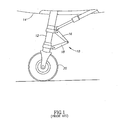
- a torque link assembly 10 attaches to a landing gear system 12 of an aircraft 14.
- the torque link assembly 10 includes an upper torque link 16 and a lower torque link 18.
- the torque link assembly 10 provides a connection between an upper landing gear strut and a lower piston. Because the piston can rotate freely in the strut, a wheel 20 mounted to it needs to be held firm to keep the aircraft rolling in a straight line. Conversely, when taxiing at low speed, say, on lineup or landing rollout, this wheel can be used to steer the aircraft 14 while on the ground.
- the torque link assembly 10 keeps the piston in line with the strut and, when connected to an actuator, permits controlled steering of aircraft 14 on the ground.
- Wheel shimmy is a condition in which the landing gear wheel or wheels oscillate from side to side along a straight line parallel to the direction of travel of the aircraft and/or rotates back and forth about the strut centerline. Wheel shimmy can be caused by a number of conditions such as low torsional stiffness, excessive freeplay in the landing gear, wheel imbalance, or worn parts. Often, however, wheel shimmy occurs even in new aircraft due to resonance between the landing gear and the airframe of the aircraft. This resonance may not be discovered until after a new aircraft is first flown and the design of the landing gear and airframe is well established. Solving a shimmy problem after an aircraft is built presents challenges because it is not usually economical to redesign and replace the landing gear in order to solve the problem. Plus increasing landing gear stiffness can typically only be accomplished with a significant weight increase. Accordingly, several different concepts have been developed for reducing or eliminating wheel shimmy in existing landing gear.
- hydraulic shimmy dampers have been used to damp wheel shimmy.
- One common method to damp shimmy consists of a hydraulic shock absorber mounted between components of the landing gear to damp shimmy motions.
- the hydraulic shock absorber generally consists of a hollow tube filled with oil.
- a rod and piston move through the fluid to generate velocity-dependent, viscous-damping forces and is typically spring loaded to the center position.
- Such designs require frequent maintenance, and temperature increases can reduce damping efficiency.
- such shimmy dampers generally do not permit 360 degree rotation of the wheel or wheels and typically are difficult to adjust to provide different levels of damping.
- shimmy damper that has been used in the past is a friction-type shimmy damper that mechanically engages a steering collar gear on a landing gear strut.
- a friction-type shimmy damper that mechanically engages a steering collar gear on a landing gear strut.
- one design includes a belleville spring washer compressed against the steering collar to damp rotation thereof. While such a shimmy damper may be functionally adequate, it is not readily retrofittable to existing landing gear assemblies and installation and/or removal of the belleville spring washers typically requires the landing gear to be substantial disassembled, as many of these types of dampers require the spring washers to be telescoped over the landing gear strut.
- Hydraulic damping (by addition of a restrictor) is also used as a feature of the many hydraulic steering actuation systems as a method to attenuate shimmy vibration. This method is popular on steerable nose landing gears as it adds the least additional weight and is generally effective. In cases where the hydraulic restrictor is not effective due to distance from the vibration source or flexibility of the structural load paths from the actuation system to the vibration, other methods may be required. This method is not an option for main landing gears which do not employ steering actuation.
- a torque link for an aircraft landing gear system incorporates a spring-damper system that includes a pair of cooperating arms.
- One arm may take the form of a structural, load carrying member, such as a beam, and the other arm may take the form of a damper assembly.
- the arms are located between a clevis portion and a lug portion of the torque link.
- the load carrying member cooperates with the damper assembly to allow some deformation that can be damped out by the damper assembly.
- the damper assembly may be bottomed out when subjected to excessive loads and then operate as rigid, structural link between the clevis and lug portions.
- the torque link may advantageously provide a dual role as a structural torque link as well as shimmy damping system.
- a torque link for a landing gear system includes a clevis portion; a lug portion distally located from the clevis portion; and a shimmy damper assembly having two load carrying arms each extending substantially between the clevis portion and the lug portion, the first arm comprising a beam member having adequate strength and stiffness, the second arm comprising a damper assembly, wherein the beam member and damper assembly cooperate as a spring-damper system integrated into the torque link.
- a torque link for a landing gear system includes a clevis portion; a lug portion distally located from the clevis portion; a rigid beam member extending between the clevis portion and the lug portion, the rigid beam arranged as a first arm of the torque link; and a shimmy damper mechanism coupled to the clevis portion and the lug portion, the shimmy damper arranged as a second arm of the torque link, the shimmy damper mechanism configured to dampen deflections of the rigid beam member under loading up to a first threshold and also configured to operate as a rigid structural member under loading that exceeds the first threshold.
- a method of handling shimmy vibrations in a landing gear system includes the steps of (1) taxiing an aircraft over a surface; (2) transferring load through a torque link; (3) inducing an amount of deformation in a beam member that operates as first structural arm of the torque link; and (4) damping out at least some of the deformation with a damping assembly that operates a second structural arm of the torque link, wherein the beam member and damping assembly cooperate to provide a spring-damper system integrated into the torque link.
- FIGURE 1 shows a conventional torque link system for a nose landing gear.
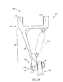
- FIGURE 2A shows a top, plan view of a torque link assembly for a landing gear system having structural arms that cooperate as a spring-damper system integrated into the torque link assembly according to an embodiment of the present invention
- FIGURE 2B shows a top, plan, partial view of yet another torque link assembly having a spherical bearing to account for misalignment according to another embodiment of the present invention
- FIGURE 2C shows a top, plan, partial view of another torque link assembly having a U-joint to account for misalignment according to another embodiment of the present invention
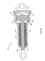
- FIGURE 3A shows a schematic, cross-sectional view of a damping assembly having a solid damping material according to an embodiment of the present invention
- FIGURE 3B shows a schematic, cross-sectional view of a damping assembly having a solid damping material with a flow orifice according to an embodiment of the present invention
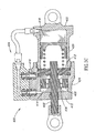
- FIGURE 3C shows a schematic, cross-sectional view of a damping assembly having a hydraulic circuit according to an embodiment of the present invention
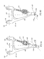
- FIGURE 4A shows a schematic top, plan view of the torque link assembly of FIGURE 1 having a damper mechanism loaded under tension according to an embodiment of the present invention
- FIGURE 4B shows a schematic top, plan view of the torque link assembly of FIGURE 1 having a damper mechanism loaded under compression according to an embodiment of the present invention.
- the following description generally relates to a torque link, also referred to as a torque arm, having a spring-damper system structurally incorporated into the design and functionality of the torque link.
- the spring portion may take the form of a structurally rigid beam while the damping portion may take the form of a damping mechanism or assembly, and where each portion functions as a structural arm of the torque link. It is appreciated that the aspects and embodiments of the torque link described herein may be utilized in the landing gear system as the upper torque link, the lower torque link, or both.
- FIGURE 2A shows a torque link assembly 100 that performs a dual role as both a structural torque link and a spring-damper system 102.
- the torque link assembly 100 may include an upper torque link 101 and a lower torque link 103.
- the torque link assembly 100 includes a clevis portion 104 distally located from a lug portion 106.
- a structural beam member 108 extends between the clevis portion 104 and the lug portion 106.
- a damping mechanism or assembly 110 is positioned between the clevis portion 104 and the lug portion 106 and operates with the structural beam member 108.
- the beam member 108 may take the form of a rigid beam that operates as a double cantilevered beam, which may be mechanically fixed to both the clevis and lug portions 104, 106, respectively, or may be integrally machined or otherwise formed therewith.
- the beam member 108 may be structurally tuned by selecting a desired, uniform cross-section for the beam member.
- the beam member 108 may be structurally tuned by selecting a cross-section that varies or tapers along its length.
- different types of cross-sectional shapes may be selected to achieve adequate strength and desired stiffness (or bending resistance), for example. Further tuning of the beam member 108 may be achieved by selecting other desired properties of the beam material, such as, but not limited to, strength, ductility, and fracture toughness.
- FIGURES 2B and 2C show torque links 100A, 100B, respectively, each having different alternatives for a misalignment capable joint 106A or 106B for coupling the upper torque link 101 to the lower torque link 103.
- FIGURE 2B shows a spherical bearing 107 coupled to the upper torque link 101.
- FIGURE 2C shows a U-joint mechanism 111 coupled to both the upper torque link 101 and the lower torque link 103.
- FIGURES 3A-3C show various devices that may be employed as the damping mechanism or assembly 110.
- the devices illustrated are meant to be only representative of how to damp out the motion of the beam member 108 with a damping mechanism 110 structurally incorporated into the torque link assembly 100.
- FIGURE 3A schematically shows an embodiment of a damping mechanism 200 having a cast solid media bonded between a rod and a cylinder to generate a desired amount of friction on the moving rod (e.g ., coulomb damping). More specifically, the illustrated damping mechanism 200 includes a piston head 202 movable in a first cylinder portion 204 and a piston rod 206 movable in a second cylinder portion 208. A damping material 210 is located in a region between the piston rod 206 and an inner surface 212 of the second cylinder portion 208.
- the damping material 210 may take the form of a solid, yet deformable material. By way of example, the damping material 210 may take the form of a silicon or rubber material with or without a filler.
- the damping material 210 may take the form of a piezoelectric material, a magneto-rheostatic material, an electro-rheostatic material, or a shape memory alloy.
- a cavity 214 where the piston head 202 is located may include a compressible, semi-compressible or non-compressible fluid such as, but not limited to, a gas, a low viscosity liquid, or a high viscosity liquid or may be void.
- a mechanical stop 216 may be coupled to the piston head 202 and sized to contact an end wall 218 after the piston head 202 has moved a desired distance within the cavity 214. In operation, the damping material 210 and the fluid within the cavity 214 both operate to provide an amount of damping for the torque link assembly 100.
- a first mechanical stop 203 may be coupled to the piston head 202 and sized to contact a second mechanical stop 209 of the cylinder body 208 after the piston head has moved the desired distance with in a cavity 214.
- the mechanical stops 203 and 216 allow the damping mechanism 200 to react tensile or compression loads.
- FIGURE 3B schematically shows an embodiment of another type of damping mechanism 300 having a cast solid media that flows through an orifice.
- the damping mechanism 300 includes a body 302 coupled to a structural link 304.
- a rod 306 received in the body 302 engages a damping material 308 that is permitted to flow through an orifice 310 extending between a first chamber 312 and a second chamber 314.
- a mechanical stop 316 is coupled to the body 302 and arranged to stop the rod 306 after the rod 306 has moved by a desired distance.
- a mechanical stop 318 is coupled to (or may be integral with) body 302 and arranged to stop the rod 306 after the rod 306 has moved the desired distance.
- FIGURE 3C schematically shows an embodiment of another type of damping mechanism 400 with a hydraulic circuit having hydraulic fluid flowing through an orifice or the damping mechanism 400 may take the form of magnetic circuit having magnetorheological fluid flowing through a magnetized orifice.
- the damping mechanism 400 includes a piston rod 402 coupled to a hydraulic circuit 404 that operates as a hydraulic fluid damper.
- the piston rod 402 includes a flow orifice or port 406 that extends through a piston head 408.
- the hydraulic circuit 404 may include multiple chambers 414, 416 and 418 in fluid communication with each other.
- the chamber 418 operates as a reservoir to account for leakage and to provide a capacity to deal with changes in temperature, which may cause expansion or contraction of the hydraulic fluid.
- the damping mechanism 400 also includes a body 424 coupled to a rod end 422. A rod 402 received in the body 424.
- a mechanical stop 412 is coupled to the body 424 and arranged to stop the rod 402 after the rod 402 has moved by a desired distance.
- a mechanical stop 410 is coupled to (or may be integral with) body 424 and arranged to stop the rod 402 after the rod 402 has moved the desired distance.
- the damping mechanism 400 operates as a rigid member.
- the torque link assembly 100 functions as a cantilevered beam member 108 between points 112 and 114. Lateral, transverse or even torsional deformations in the beam member 108 may be damped out by operation of the damping mechanism 110. Such deformations are schematically indicated with arrows 116 at point 114. Although the arrows 116 is shown in the illustrated directions; it is appreciated that the deformations may be in other directions.
- the damping mechanism 110 may be configured to damp out at least some, if not all, of the aforementioned deformations. In situations where the deformation of the beam member 108 becomes excessive, the damping mechanism 110 may be configured to bottom and act as a rigid member between points 114 and 118. In this bottoming out scenario, the torque link assembly 100 would react loads at point 114 through the beam member 108 acting as a tension or compression member and the bottomed-out'damping mechanism 110 correspondingly acting as a compression or tension member, respectively.
- the beam is designed for structural torque loads when combined with the bottomed-out damping mechanism 110; meaning the beam member 108 is sized for structural tension, compression, buckling or crippling, etc.
- the illustrated embodiments each provide a torque link with integrated flexibility for damping out shimmy vibration and where the damping mechanism is structurally incorporated into the torque link (e.g., upper or lower torque link).
- the damping mechanism In a lower torque link, the damping mechanism would be closer to the ground, which is the source of the vibrational loads, and therefore may be advantageously more effective.
- the described embodiments or variations thereof may be lighter since it could replace part of the torque link system rather than just adding a separate damping mechanism.
- FIGURES 4A and 4B schematically shows how loading of the torque link assembly 100 and more specifically loading of the upper torque link 101 can change the stresses in the beam 108 and damping mechanism 110, respectively.
- FIGURE 4A shows that loading of the torque link 101 as generally indicated by upper load vectors 120 and lower load vector 122 causes the damping mechanism 110 to "fully extend” and thus be placed under a tensile stress while the beam 108 is placed under compression and bending stresses. Under such a loading condition, the beam 108 may deflect from point 124a to point 124b along a line of action 126.
- the deflection of the beam 108 is exaggerated to clarify the stress profile and operation of the torque link 101 under load with the damping mechanism 110 fully extended as schematically illustrated by a position of a piston 128 within a cylinder 130.
- FIGURE 4B shows the upper torque link 101 under an opposite loading condition as that from FIGURE 4A .
- FIGURE 4B shows that loading of the torque link 101 as generally indicated by upper load vectors 132 and lower load vector 134 causes the damping mechanism 110 to "bottom out” and thus be placed under a compressive stress while the beam 108 is placed under tension and bending stresses. Under this loading condition, the beam 108 may deflect from point 136a to point 136b along a line of action 138. In the illustrated embodiment, the deflection of the beam 108 is exaggerated to clarify the stress profile and operation of the torque link 101 under load with the damping mechanism 110 bottomed out as schematically illustrated by the position of the piston 128 within the cylinder 130.
Landscapes
- Engineering & Computer Science (AREA)
- Mechanical Engineering (AREA)
- Aviation & Aerospace Engineering (AREA)
- Vibration Dampers (AREA)
- Vibration Prevention Devices (AREA)
Abstract
Description
- This invention relates to a torque link for a landing gear system, and more specifically a torque having a shimmy damper mechanism.
- As shown in
FIGURE 1 , atorque link assembly 10 attaches to alanding gear system 12 of anaircraft 14. Thetorque link assembly 10 includes anupper torque link 16 and alower torque link 18. As illustrated, thetorque link assembly 10 provides a connection between an upper landing gear strut and a lower piston. Because the piston can rotate freely in the strut, awheel 20 mounted to it needs to be held firm to keep the aircraft rolling in a straight line. Conversely, when taxiing at low speed, say, on lineup or landing rollout, this wheel can be used to steer theaircraft 14 while on the ground. Thetorque link assembly 10 keeps the piston in line with the strut and, when connected to an actuator, permits controlled steering ofaircraft 14 on the ground. - Wheel shimmy is a condition in which the landing gear wheel or wheels oscillate from side to side along a straight line parallel to the direction of travel of the aircraft and/or rotates back and forth about the strut centerline. Wheel shimmy can be caused by a number of conditions such as low torsional stiffness, excessive freeplay in the landing gear, wheel imbalance, or worn parts. Often, however, wheel shimmy occurs even in new aircraft due to resonance between the landing gear and the airframe of the aircraft. This resonance may not be discovered until after a new aircraft is first flown and the design of the landing gear and airframe is well established. Solving a shimmy problem after an aircraft is built presents challenges because it is not usually economical to redesign and replace the landing gear in order to solve the problem. Plus increasing landing gear stiffness can typically only be accomplished with a significant weight increase. Accordingly, several different concepts have been developed for reducing or eliminating wheel shimmy in existing landing gear.
- For example, hydraulic shimmy dampers have been used to damp wheel shimmy. One common method to damp shimmy consists of a hydraulic shock absorber mounted between components of the landing gear to damp shimmy motions. The hydraulic shock absorber generally consists of a hollow tube filled with oil. A rod and piston move through the fluid to generate velocity-dependent, viscous-damping forces and is typically spring loaded to the center position. Such designs require frequent maintenance, and temperature increases can reduce damping efficiency. Further, such shimmy dampers generally do not permit 360 degree rotation of the wheel or wheels and typically are difficult to adjust to provide different levels of damping.
- Another type of shimmy damper that has been used in the past is a friction-type shimmy damper that mechanically engages a steering collar gear on a landing gear strut. For example, one design includes a belleville spring washer compressed against the steering collar to damp rotation thereof. While such a shimmy damper may be functionally adequate, it is not readily retrofittable to existing landing gear assemblies and installation and/or removal of the belleville spring washers typically requires the landing gear to be substantial disassembled, as many of these types of dampers require the spring washers to be telescoped over the landing gear strut.
- Hydraulic damping (by addition of a restrictor) is also used as a feature of the many hydraulic steering actuation systems as a method to attenuate shimmy vibration. This method is popular on steerable nose landing gears as it adds the least additional weight and is generally effective. In cases where the hydraulic restrictor is not effective due to distance from the vibration source or flexibility of the structural load paths from the actuation system to the vibration, other methods may be required. This method is not an option for main landing gears which do not employ steering actuation.
- A torque link for an aircraft landing gear system incorporates a spring-damper system that includes a pair of cooperating arms. One arm may take the form of a structural, load carrying member, such as a beam, and the other arm may take the form of a damper assembly. The arms are located between a clevis portion and a lug portion of the torque link. The load carrying member cooperates with the damper assembly to allow some deformation that can be damped out by the damper assembly. In one embodiment, the damper assembly may be bottomed out when subjected to excessive loads and then operate as rigid, structural link between the clevis and lug portions. The torque link may advantageously provide a dual role as a structural torque link as well as shimmy damping system.
- In one example of the invention, a torque link for a landing gear system includes a clevis portion; a lug portion distally located from the clevis portion; and a shimmy damper assembly having two load carrying arms each extending substantially between the clevis portion and the lug portion, the first arm comprising a beam member having adequate strength and stiffness, the second arm comprising a damper assembly, wherein the beam member and damper assembly cooperate as a spring-damper system integrated into the torque link.
- In another example of the invention, a torque link for a landing gear system includes a clevis portion; a lug portion distally located from the clevis portion; a rigid beam member extending between the clevis portion and the lug portion, the rigid beam arranged as a first arm of the torque link; and a shimmy damper mechanism coupled to the clevis portion and the lug portion, the shimmy damper arranged as a second arm of the torque link, the shimmy damper mechanism configured to dampen deflections of the rigid beam member under loading up to a first threshold and also configured to operate as a rigid structural member under loading that exceeds the first threshold.
- In yet another example of the invention, a method of handling shimmy vibrations in a landing gear system includes the steps of (1) taxiing an aircraft over a surface; (2) transferring load through a torque link; (3) inducing an amount of deformation in a beam member that operates as first structural arm of the torque link; and (4) damping out at least some of the deformation with a damping assembly that operates a second structural arm of the torque link, wherein the beam member and damping assembly cooperate to provide a spring-damper system integrated into the torque link.
- The preferred and alternative embodiments of the present invention are described in detail below with reference to the following drawings.
-
FIGURE 1 shows a conventional torque link system for a nose landing gear. -
FIGURE 2A shows a top, plan view of a torque link assembly for a landing gear system having structural arms that cooperate as a spring-damper system integrated into the torque link assembly according to an embodiment of the present invention; -
FIGURE 2B shows a top, plan, partial view of yet another torque link assembly having a spherical bearing to account for misalignment according to another embodiment of the present invention; -
FIGURE 2C shows a top, plan, partial view of another torque link assembly having a U-joint to account for misalignment according to another embodiment of the present invention; -
FIGURE 3A shows a schematic, cross-sectional view of a damping assembly having a solid damping material according to an embodiment of the present invention; -
FIGURE 3B shows a schematic, cross-sectional view of a damping assembly having a solid damping material with a flow orifice according to an embodiment of the present invention; -
FIGURE 3C shows a schematic, cross-sectional view of a damping assembly having a hydraulic circuit according to an embodiment of the present invention; -
FIGURE 4A shows a schematic top, plan view of the torque link assembly ofFIGURE 1 having a damper mechanism loaded under tension according to an embodiment of the present invention; and -
FIGURE 4B shows a schematic top, plan view of the torque link assembly ofFIGURE 1 having a damper mechanism loaded under compression according to an embodiment of the present invention. - In the following description, certain specific details are set forth in order to provide a thorough understanding of various embodiments of the invention. However, one skilled in the art will understand that the invention may be practiced without these details. In other instances, well-known structures associated with aircraft, aircraft landing gear systems, torque links or torque links, and damping mechanisms along with the operation thereof have not necessarily been shown or described in detail to avoid unnecessarily obscuring descriptions of the embodiments of the invention.
- The following description generally relates to a torque link, also referred to as a torque arm, having a spring-damper system structurally incorporated into the design and functionality of the torque link. The spring portion may take the form of a structurally rigid beam while the damping portion may take the form of a damping mechanism or assembly, and where each portion functions as a structural arm of the torque link. It is appreciated that the aspects and embodiments of the torque link described herein may be utilized in the landing gear system as the upper torque link, the lower torque link, or both.
-
FIGURE 2A shows atorque link assembly 100 that performs a dual role as both a structural torque link and a spring-damper system 102. Thetorque link assembly 100 may include anupper torque link 101 and alower torque link 103. In one embodiment, thetorque link assembly 100 includes aclevis portion 104 distally located from alug portion 106. Referring specifically to theupper torque link 101, astructural beam member 108 extends between theclevis portion 104 and thelug portion 106. In addition, a damping mechanism orassembly 110 is positioned between theclevis portion 104 and thelug portion 106 and operates with thestructural beam member 108. - The
beam member 108 may take the form of a rigid beam that operates as a double cantilevered beam, which may be mechanically fixed to both the clevis andlug portions beam member 108 may be structurally tuned by selecting a desired, uniform cross-section for the beam member. In another embodiment, thebeam member 108 may be structurally tuned by selecting a cross-section that varies or tapers along its length. In addition or alternatively, different types of cross-sectional shapes may be selected to achieve adequate strength and desired stiffness (or bending resistance), for example. Further tuning of thebeam member 108 may be achieved by selecting other desired properties of the beam material, such as, but not limited to, strength, ductility, and fracture toughness. -
FIGURES 2B and 2C show torque links 100A, 100B, respectively, each having different alternatives for a misalignment capable joint 106A or 106B for coupling theupper torque link 101 to thelower torque link 103. By way of example,FIGURE 2B shows aspherical bearing 107 coupled to theupper torque link 101.FIGURE 2C shows aU-joint mechanism 111 coupled to both theupper torque link 101 and thelower torque link 103. -
FIGURES 3A-3C show various devices that may be employed as the damping mechanism orassembly 110. The devices illustrated are meant to be only representative of how to damp out the motion of thebeam member 108 with a dampingmechanism 110 structurally incorporated into thetorque link assembly 100. -
FIGURE 3A schematically shows an embodiment of a dampingmechanism 200 having a cast solid media bonded between a rod and a cylinder to generate a desired amount of friction on the moving rod (e.g., coulomb damping). More specifically, the illustrated dampingmechanism 200 includes apiston head 202 movable in afirst cylinder portion 204 and apiston rod 206 movable in asecond cylinder portion 208. A dampingmaterial 210 is located in a region between thepiston rod 206 and aninner surface 212 of thesecond cylinder portion 208. The dampingmaterial 210 may take the form of a solid, yet deformable material. By way of example, the dampingmaterial 210 may take the form of a silicon or rubber material with or without a filler. In addition, the dampingmaterial 210 may take the form of a piezoelectric material, a magneto-rheostatic material, an electro-rheostatic material, or a shape memory alloy. Acavity 214 where thepiston head 202 is located may include a compressible, semi-compressible or non-compressible fluid such as, but not limited to, a gas, a low viscosity liquid, or a high viscosity liquid or may be void. Amechanical stop 216 may be coupled to thepiston head 202 and sized to contact anend wall 218 after thepiston head 202 has moved a desired distance within thecavity 214. In operation, the dampingmaterial 210 and the fluid within thecavity 214 both operate to provide an amount of damping for thetorque link assembly 100. A firstmechanical stop 203 may be coupled to thepiston head 202 and sized to contact a secondmechanical stop 209 of thecylinder body 208 after the piston head has moved the desired distance with in acavity 214. The mechanical stops 203 and 216 allow the dampingmechanism 200 to react tensile or compression loads. -
FIGURE 3B schematically shows an embodiment of another type of dampingmechanism 300 having a cast solid media that flows through an orifice. More specifically, the dampingmechanism 300 includes abody 302 coupled to astructural link 304. Arod 306 received in thebody 302 engages a dampingmaterial 308 that is permitted to flow through anorifice 310 extending between afirst chamber 312 and asecond chamber 314. Amechanical stop 316 is coupled to thebody 302 and arranged to stop therod 306 after therod 306 has moved by a desired distance. A mechanical stop 318 is coupled to (or may be integral with)body 302 and arranged to stop therod 306 after therod 306 has moved the desired distance. When therod 306 is engaged with thestop 316 or 318, the dampingmechanism 300 operates as a rigid member. -
FIGURE 3C schematically shows an embodiment of another type of dampingmechanism 400 with a hydraulic circuit having hydraulic fluid flowing through an orifice or the dampingmechanism 400 may take the form of magnetic circuit having magnetorheological fluid flowing through a magnetized orifice. For purposes of brevity, the hydraulic circuit embodiment will be described herein. The dampingmechanism 400 includes apiston rod 402 coupled to ahydraulic circuit 404 that operates as a hydraulic fluid damper. In the illustrated embodiment, thepiston rod 402 includes a flow orifice orport 406 that extends through apiston head 408. Thehydraulic circuit 404 may includemultiple chambers chamber 418 operates as a reservoir to account for leakage and to provide a capacity to deal with changes in temperature, which may cause expansion or contraction of the hydraulic fluid. The dampingmechanism 400 also includes abody 424 coupled to arod end 422. Arod 402 received in thebody 424. Amechanical stop 412 is coupled to thebody 424 and arranged to stop therod 402 after therod 402 has moved by a desired distance. Amechanical stop 410 is coupled to (or may be integral with)body 424 and arranged to stop therod 402 after therod 402 has moved the desired distance. When therod 402 is engaged with thestop mechanism 400 operates as a rigid member. - Referring back to
FIGURE 2A , thetorque link assembly 100 functions as acantilevered beam member 108 betweenpoints beam member 108 may be damped out by operation of the dampingmechanism 110. Such deformations are schematically indicated witharrows 116 atpoint 114. Although thearrows 116 is shown in the illustrated directions; it is appreciated that the deformations may be in other directions. - The damping
mechanism 110 may be configured to damp out at least some, if not all, of the aforementioned deformations. In situations where the deformation of thebeam member 108 becomes excessive, the dampingmechanism 110 may be configured to bottom and act as a rigid member betweenpoints torque link assembly 100 would react loads atpoint 114 through thebeam member 108 acting as a tension or compression member and the bottomed-out'damping mechanism 110 correspondingly acting as a compression or tension member, respectively. In one embodiment, the beam is designed for structural torque loads when combined with the bottomed-out dampingmechanism 110; meaning thebeam member 108 is sized for structural tension, compression, buckling or crippling, etc. - The illustrated embodiments each provide a torque link with integrated flexibility for damping out shimmy vibration and where the damping mechanism is structurally incorporated into the torque link (e.g., upper or lower torque link). In a lower torque link, the damping mechanism would be closer to the ground, which is the source of the vibrational loads, and therefore may be advantageously more effective. In addition, the described embodiments or variations thereof may be lighter since it could replace part of the torque link system rather than just adding a separate damping mechanism.
-
FIGURES 4A and 4B schematically shows how loading of thetorque link assembly 100 and more specifically loading of theupper torque link 101 can change the stresses in thebeam 108 and dampingmechanism 110, respectively.FIGURE 4A shows that loading of thetorque link 101 as generally indicated byupper load vectors 120 andlower load vector 122 causes the dampingmechanism 110 to "fully extend" and thus be placed under a tensile stress while thebeam 108 is placed under compression and bending stresses. Under such a loading condition, thebeam 108 may deflect frompoint 124a to point 124b along a line ofaction 126. In the illustrated embodiment, the deflection of thebeam 108 is exaggerated to clarify the stress profile and operation of thetorque link 101 under load with the dampingmechanism 110 fully extended as schematically illustrated by a position of apiston 128 within acylinder 130. -
FIGURE 4B shows theupper torque link 101 under an opposite loading condition as that fromFIGURE 4A . In particular,FIGURE 4B shows that loading of thetorque link 101 as generally indicated byupper load vectors 132 andlower load vector 134 causes the dampingmechanism 110 to "bottom out" and thus be placed under a compressive stress while thebeam 108 is placed under tension and bending stresses. Under this loading condition, thebeam 108 may deflect frompoint 136a to point 136b along a line ofaction 138. In the illustrated embodiment, the deflection of thebeam 108 is exaggerated to clarify the stress profile and operation of thetorque link 101 under load with the dampingmechanism 110 bottomed out as schematically illustrated by the position of thepiston 128 within thecylinder 130. - While the preferred embodiment of the invention has been illustrated and described, as noted above, many changes can be made without departing from the spirit and scope of the invention. Accordingly, the scope of the invention is not limited by the disclosure of the preferred embodiment. Instead, the invention should be determined entirely by reference to the claims that follow.
Claims (15)
- A torque link for a landing gear system, the torque link comprising:a clevis portion;a lug portion distally located from the clevis portion; anda shimmy damper assembly having two load carrying arms each extending substantially between the clevis portion and the lug portion, the first arm comprising a beam member having a desired stiffness, the second arm comprising a damper assembly, wherein the beam member and damper assembly cooperate as a spring-damper system integrated into the torque link and provide a desired structured load path under high loads.
- The torque link of claim 1, wherein the first arm includes a constant cross-sectional thickness.
- The torque link of claim 1, wherein the first arm includes a non-constant cross-sectional thickness.
- The torque link of claim 1, wherein the first arm is integrally formed with at least one of either the clevis portion or the lug portion.
- The torque link of claim 1, wherein the second arm is pin-connected to the clevis portion and the lug portion, respectively.
- The torque link of claim 1, wherein the shimmy damper assembly includes a cast media damping material.
- The torque link of claim 1, wherein the shimmy damper assembly includes a solid damping material having a hydraulic orifice to permit fluid communication through the damping material.
- The torque link of claim 1, wherein the shimmy damper assembly includes a hydraulic circuit.
- The torque link of claim 1, wherein the shimmy damper assembly includes a magnetorheological material having an orifice to permit fluid communication through the material.
- The torque link of claim 1, wherein the shimmy damper assembly includes a rod frictionally received in and movable within a channel to provide an amount of damping.
- The torque link of claim 1, wherein
the beam member of the first arm comprises a rigid beam member extending between the clevis portion and the lug portion; and
the damper assembly of the second arm comprises a shimmy damper mechanism coupled to the
clevis portion and the lug portion, the shimmy damper mechanism configured to dampen deflections of the rigid beam member under loading up to a first threshold and also configured to operate as a rigid structural member under loading that exceeds the first threshold. - The torque link of claim 11, wherein the rigid beam member includes a cross-sectional thickness that varies along a length of the beam member.
- The torque link of claim 11, wherein the shimmy damper mechanism includes a rod frictionally received in and movable within a channel to provide an amount of damping.
- A method of handling shimmy vibrations in a landing gear system, the method comprising:taxiing an aircraft over a surface;transferring load through a torque link;inducing an amount of deformation in a beam member that operates as first
structural arm of the torque link; anddamping out at least some of the deformation with a damping assembly that
operates a second structural arm of the torque link, wherein the beam member and damping assembly cooperate to provide a spring-damper system integrated into the torque link. - The method of claim 14, wherein damping out at least some of the deformation with a damping assembly includes damping out at least some of the deformation through at least one of:a case media material;a hydraulic circuit;a magnetorheological material;a friction joint.
Applications Claiming Priority (1)
| Application Number | Priority Date | Filing Date | Title |
|---|---|---|---|
| US12/818,040 US8292218B2 (en) | 2010-06-17 | 2010-06-17 | Torque link with shimmy damper |
Publications (3)
| Publication Number | Publication Date |
|---|---|
| EP2397407A2 true EP2397407A2 (en) | 2011-12-21 |
| EP2397407A3 EP2397407A3 (en) | 2014-01-15 |
| EP2397407B1 EP2397407B1 (en) | 2015-08-05 |
Family
ID=44590975
Family Applications (1)
| Application Number | Title | Priority Date | Filing Date |
|---|---|---|---|
| EP11250580.5A Active EP2397407B1 (en) | 2010-06-17 | 2011-06-03 | Torque link with shimmy damper |
Country Status (3)
| Country | Link |
|---|---|
| US (2) | US8292218B2 (en) |
| EP (1) | EP2397407B1 (en) |
| CA (1) | CA2743532A1 (en) |
Cited By (1)
| Publication number | Priority date | Publication date | Assignee | Title |
|---|---|---|---|---|
| CN111924091A (en) * | 2020-08-18 | 2020-11-13 | 泊鹭(荆门)飞机有限公司 | Detachable aircraft landing gear suitable for stop on rough road |
Families Citing this family (11)
| Publication number | Priority date | Publication date | Assignee | Title |
|---|---|---|---|---|
| US8292218B2 (en) * | 2010-06-17 | 2012-10-23 | Goodrich Corporation | Torque link with shimmy damper |
| JP5985385B2 (en) * | 2012-12-27 | 2016-09-06 | 住友重機械工業株式会社 | Gear motor |
| US9303709B2 (en) | 2014-08-11 | 2016-04-05 | Ggodrich Corporation | Shock damper |
| EP3078877B1 (en) | 2015-04-10 | 2017-12-27 | Safran Landing Systems UK Limited | Hydraulic shock absorber |
| KR101855080B1 (en) | 2017-09-20 | 2018-05-10 | 주식회사 포메탈 | Method for manufacturing landing gear for aircraft |
| US11396372B2 (en) * | 2018-08-30 | 2022-07-26 | Textron Innovations Inc. | Redundant impact-resistant structure |
| US12384530B2 (en) | 2021-12-14 | 2025-08-12 | Goodrich Corporation | Self-sustaining shimmy damper system for landing gear shock strut assemblies |
| CN116025659B (en) * | 2023-01-10 | 2024-11-26 | 烟台大学 | Self-resetting fitness damper based on magnetorheological material |
| US12583635B2 (en) | 2024-01-12 | 2026-03-24 | Textron Systems Corporation | Utilizing multi-directional energy-absorbing landing gear for vertical takeoff and landing |
| CN117922821B (en) * | 2024-03-06 | 2024-09-10 | 中国兵器装备集团自动化研究所有限公司 | Front wheel steering anti-swing device of aircraft and unmanned aerial vehicle |
| CN119239924B (en) * | 2024-11-07 | 2025-09-19 | 中南大学 | Variable-rigidity shock-absorbing aircraft landing gear and aircraft |
Family Cites Families (12)
| Publication number | Priority date | Publication date | Assignee | Title |
|---|---|---|---|---|
| US2372710A (en) * | 1941-12-11 | 1945-04-03 | Houdaille Hershey Corp | Hydraulic steering motor and shimmy dampener for airplane landing gear wheels |
| US2481150A (en) * | 1946-09-19 | 1949-09-06 | Robert T A Pifer | Shock-absorbing apparatus |
| GB1019132A (en) * | 1963-08-06 | 1966-02-02 | Dowty Rotol Ltd | Aircraft undercarriages |
| US3430896A (en) * | 1967-05-02 | 1969-03-04 | United Aircraft Corp | Shimmy damper |
| US3499621A (en) | 1967-09-06 | 1970-03-10 | Mc Donnell Douglas Corp | Torque linkage damper |
| FR2144558B1 (en) * | 1971-07-05 | 1974-12-13 | Messier Hispano Sa | |
| FR2502578A1 (en) * | 1981-03-27 | 1982-10-01 | Messier Hispano Sa | LANDING TRAIN TYPE TRIPODE |
| FR2555945A1 (en) * | 1983-12-02 | 1985-06-07 | Berthier Christian | Suspension element, particularly for a vehicle; suspension equipped with such an element; ultra light aircraft equipped with such a suspension |
| US5224668A (en) | 1991-12-09 | 1993-07-06 | Mcdonnell Douglas Corporation | Torque linkage damper |
| US7571876B2 (en) * | 2004-01-20 | 2009-08-11 | Lord Corporation | Aircraft landing gear assembly shimmy damper |
| DE102009011359A1 (en) * | 2008-03-05 | 2009-09-10 | Goodrich Corp. | Flutter damper for aircraft landing gear |
| US8292218B2 (en) * | 2010-06-17 | 2012-10-23 | Goodrich Corporation | Torque link with shimmy damper |
-
2010
- 2010-06-17 US US12/818,040 patent/US8292218B2/en active Active
-
2011
- 2011-06-03 EP EP11250580.5A patent/EP2397407B1/en active Active
- 2011-06-16 CA CA2743532A patent/CA2743532A1/en not_active Abandoned
-
2012
- 2012-09-14 US US13/618,561 patent/US8448899B2/en active Active
Non-Patent Citations (1)
| Title |
|---|
| None |
Cited By (2)
| Publication number | Priority date | Publication date | Assignee | Title |
|---|---|---|---|---|
| CN111924091A (en) * | 2020-08-18 | 2020-11-13 | 泊鹭(荆门)飞机有限公司 | Detachable aircraft landing gear suitable for stop on rough road |
| CN111924091B (en) * | 2020-08-18 | 2021-11-16 | 东台汇赢创融科技发展有限公司 | Detachable aircraft landing gear suitable for stop on rough road |
Also Published As
| Publication number | Publication date |
|---|---|
| US8448899B2 (en) | 2013-05-28 |
| US20130009003A1 (en) | 2013-01-10 |
| US8292218B2 (en) | 2012-10-23 |
| CA2743532A1 (en) | 2011-12-17 |
| EP2397407B1 (en) | 2015-08-05 |
| US20110309192A1 (en) | 2011-12-22 |
| EP2397407A3 (en) | 2014-01-15 |
Similar Documents
| Publication | Publication Date | Title |
|---|---|---|
| EP2397407B1 (en) | Torque link with shimmy damper | |
| KR101094215B1 (en) | Air suspension | |
| US8371562B2 (en) | Double path mount for cab suspension with tilting function | |
| US10974821B2 (en) | Aircraft undercarriage fitted with a shimmy-attenuator device | |
| US9200695B2 (en) | Spring and damper system, in particular for an assembly mount in a motor vehicle | |
| US11192641B2 (en) | Aircraft and landing gear provided with at least one pair of shock absorbers, and a method performed by said landing gear | |
| EP3048046B1 (en) | Friction-based shimmy damper for landing gear | |
| CA3217872A1 (en) | Damping system for a cabin of a movable work machine | |
| JP5539629B2 (en) | Piston cylinder assembly | |
| CN108622377B (en) | Aircraft landing gear assembly | |
| EP3357813B1 (en) | Hydraulic torque compensation device | |
| US10589848B2 (en) | Landing-gear assembly for an aircraft, the landing-gear assembly including a secondary shimmy damper | |
| US8714321B2 (en) | Long travel shock absorber | |
| SE508080C2 (en) | Device and use in shock absorbers | |
| EP1883758B1 (en) | Preloaded one-way valve accumulator | |
| US12384530B2 (en) | Self-sustaining shimmy damper system for landing gear shock strut assemblies | |
| EP3647151B1 (en) | Wheel axle guiding assembly with load dependent pressurising means | |
| CA2084838C (en) | Torque linkage damper | |
| EP4198334A1 (en) | Self-sustaining shimmy damper system for landing gear shock strut assemblies | |
| RU126073U1 (en) | HYDRAULIC VEHICLE DUMP VEHICLE VEHICLES | |
| US20250145281A1 (en) | Strut and landing gear including strut | |
| US20230257110A1 (en) | Compression-Force Spike Reduction | |
| KR20240075832A (en) | Rolling damper and suspension system with asymmetric rolling motion and symmetric vertical motion, method for mounting the same | |
| KR20240045287A (en) | suspension with air reservoir | |
| KR19990013191U (en) | Stroke-sensitive Shock Absorber |
Legal Events
| Date | Code | Title | Description |
|---|---|---|---|
| 17P | Request for examination filed |
Effective date: 20110614 |
|
| AK | Designated contracting states |
Kind code of ref document: A2 Designated state(s): AL AT BE BG CH CY CZ DE DK EE ES FI FR GB GR HR HU IE IS IT LI LT LU LV MC MK MT NL NO PL PT RO RS SE SI SK SM TR |
|
| AX | Request for extension of the european patent |
Extension state: BA ME |
|
| PUAI | Public reference made under article 153(3) epc to a published international application that has entered the european phase |
Free format text: ORIGINAL CODE: 0009012 |
|
| PUAL | Search report despatched |
Free format text: ORIGINAL CODE: 0009013 |
|
| AK | Designated contracting states |
Kind code of ref document: A3 Designated state(s): AL AT BE BG CH CY CZ DE DK EE ES FI FR GB GR HR HU IE IS IT LI LT LU LV MC MK MT NL NO PL PT RO RS SE SI SK SM TR |
|
| AX | Request for extension of the european patent |
Extension state: BA ME |
|
| RIC1 | Information provided on ipc code assigned before grant |
Ipc: B64C 25/50 20060101AFI20131212BHEP |
|
| GRAP | Despatch of communication of intention to grant a patent |
Free format text: ORIGINAL CODE: EPIDOSNIGR1 |
|
| INTG | Intention to grant announced |
Effective date: 20141022 |
|
| GRAP | Despatch of communication of intention to grant a patent |
Free format text: ORIGINAL CODE: EPIDOSNIGR1 |
|
| INTG | Intention to grant announced |
Effective date: 20150313 |
|
| GRAS | Grant fee paid |
Free format text: ORIGINAL CODE: EPIDOSNIGR3 |
|
| GRAA | (expected) grant |
Free format text: ORIGINAL CODE: 0009210 |
|
| AK | Designated contracting states |
Kind code of ref document: B1 Designated state(s): AL AT BE BG CH CY CZ DE DK EE ES FI FR GB GR HR HU IE IS IT LI LT LU LV MC MK MT NL NO PL PT RO RS SE SI SK SM TR |
|
| REG | Reference to a national code |
Ref country code: GB Ref legal event code: FG4D |
|
| REG | Reference to a national code |
Ref country code: CH Ref legal event code: EP |
|
| REG | Reference to a national code |
Ref country code: AT Ref legal event code: REF Ref document number: 740538 Country of ref document: AT Kind code of ref document: T Effective date: 20150815 |
|
| REG | Reference to a national code |
Ref country code: IE Ref legal event code: FG4D |
|
| REG | Reference to a national code |
Ref country code: DE Ref legal event code: R096 Ref document number: 602011018420 Country of ref document: DE |
|
| REG | Reference to a national code |
Ref country code: AT Ref legal event code: MK05 Ref document number: 740538 Country of ref document: AT Kind code of ref document: T Effective date: 20150805 |
|
| REG | Reference to a national code |
Ref country code: LT Ref legal event code: MG4D |
|
| REG | Reference to a national code |
Ref country code: NL Ref legal event code: MP Effective date: 20150805 |
|
| PG25 | Lapsed in a contracting state [announced via postgrant information from national office to epo] |
Ref country code: LV Free format text: LAPSE BECAUSE OF FAILURE TO SUBMIT A TRANSLATION OF THE DESCRIPTION OR TO PAY THE FEE WITHIN THE PRESCRIBED TIME-LIMIT Effective date: 20150805 Ref country code: NO Free format text: LAPSE BECAUSE OF FAILURE TO SUBMIT A TRANSLATION OF THE DESCRIPTION OR TO PAY THE FEE WITHIN THE PRESCRIBED TIME-LIMIT Effective date: 20151105 Ref country code: GR Free format text: LAPSE BECAUSE OF FAILURE TO SUBMIT A TRANSLATION OF THE DESCRIPTION OR TO PAY THE FEE WITHIN THE PRESCRIBED TIME-LIMIT Effective date: 20151106 Ref country code: LT Free format text: LAPSE BECAUSE OF FAILURE TO SUBMIT A TRANSLATION OF THE DESCRIPTION OR TO PAY THE FEE WITHIN THE PRESCRIBED TIME-LIMIT Effective date: 20150805 Ref country code: FI Free format text: LAPSE BECAUSE OF FAILURE TO SUBMIT A TRANSLATION OF THE DESCRIPTION OR TO PAY THE FEE WITHIN THE PRESCRIBED TIME-LIMIT Effective date: 20150805 |
|
| PG25 | Lapsed in a contracting state [announced via postgrant information from national office to epo] |
Ref country code: SE Free format text: LAPSE BECAUSE OF FAILURE TO SUBMIT A TRANSLATION OF THE DESCRIPTION OR TO PAY THE FEE WITHIN THE PRESCRIBED TIME-LIMIT Effective date: 20150805 Ref country code: AT Free format text: LAPSE BECAUSE OF FAILURE TO SUBMIT A TRANSLATION OF THE DESCRIPTION OR TO PAY THE FEE WITHIN THE PRESCRIBED TIME-LIMIT Effective date: 20150805 Ref country code: PL Free format text: LAPSE BECAUSE OF FAILURE TO SUBMIT A TRANSLATION OF THE DESCRIPTION OR TO PAY THE FEE WITHIN THE PRESCRIBED TIME-LIMIT Effective date: 20150805 Ref country code: HR Free format text: LAPSE BECAUSE OF FAILURE TO SUBMIT A TRANSLATION OF THE DESCRIPTION OR TO PAY THE FEE WITHIN THE PRESCRIBED TIME-LIMIT Effective date: 20150805 Ref country code: RS Free format text: LAPSE BECAUSE OF FAILURE TO SUBMIT A TRANSLATION OF THE DESCRIPTION OR TO PAY THE FEE WITHIN THE PRESCRIBED TIME-LIMIT Effective date: 20150805 Ref country code: PT Free format text: LAPSE BECAUSE OF FAILURE TO SUBMIT A TRANSLATION OF THE DESCRIPTION OR TO PAY THE FEE WITHIN THE PRESCRIBED TIME-LIMIT Effective date: 20151207 Ref country code: IS Free format text: LAPSE BECAUSE OF FAILURE TO SUBMIT A TRANSLATION OF THE DESCRIPTION OR TO PAY THE FEE WITHIN THE PRESCRIBED TIME-LIMIT Effective date: 20151205 Ref country code: ES Free format text: LAPSE BECAUSE OF FAILURE TO SUBMIT A TRANSLATION OF THE DESCRIPTION OR TO PAY THE FEE WITHIN THE PRESCRIBED TIME-LIMIT Effective date: 20150805 |
|
| PG25 | Lapsed in a contracting state [announced via postgrant information from national office to epo] |
Ref country code: NL Free format text: LAPSE BECAUSE OF FAILURE TO SUBMIT A TRANSLATION OF THE DESCRIPTION OR TO PAY THE FEE WITHIN THE PRESCRIBED TIME-LIMIT Effective date: 20150805 |
|
| PG25 | Lapsed in a contracting state [announced via postgrant information from national office to epo] |
Ref country code: EE Free format text: LAPSE BECAUSE OF FAILURE TO SUBMIT A TRANSLATION OF THE DESCRIPTION OR TO PAY THE FEE WITHIN THE PRESCRIBED TIME-LIMIT Effective date: 20150805 Ref country code: IT Free format text: LAPSE BECAUSE OF FAILURE TO SUBMIT A TRANSLATION OF THE DESCRIPTION OR TO PAY THE FEE WITHIN THE PRESCRIBED TIME-LIMIT Effective date: 20150805 Ref country code: SK Free format text: LAPSE BECAUSE OF FAILURE TO SUBMIT A TRANSLATION OF THE DESCRIPTION OR TO PAY THE FEE WITHIN THE PRESCRIBED TIME-LIMIT Effective date: 20150805 Ref country code: DK Free format text: LAPSE BECAUSE OF FAILURE TO SUBMIT A TRANSLATION OF THE DESCRIPTION OR TO PAY THE FEE WITHIN THE PRESCRIBED TIME-LIMIT Effective date: 20150805 Ref country code: CZ Free format text: LAPSE BECAUSE OF FAILURE TO SUBMIT A TRANSLATION OF THE DESCRIPTION OR TO PAY THE FEE WITHIN THE PRESCRIBED TIME-LIMIT Effective date: 20150805 |
|
| REG | Reference to a national code |
Ref country code: DE Ref legal event code: R097 Ref document number: 602011018420 Country of ref document: DE |
|
| REG | Reference to a national code |
Ref country code: FR Ref legal event code: PLFP Year of fee payment: 6 |
|
| PG25 | Lapsed in a contracting state [announced via postgrant information from national office to epo] |
Ref country code: RO Free format text: LAPSE BECAUSE OF FAILURE TO SUBMIT A TRANSLATION OF THE DESCRIPTION OR TO PAY THE FEE WITHIN THE PRESCRIBED TIME-LIMIT Effective date: 20150805 |
|
| PLBE | No opposition filed within time limit |
Free format text: ORIGINAL CODE: 0009261 |
|
| STAA | Information on the status of an ep patent application or granted ep patent |
Free format text: STATUS: NO OPPOSITION FILED WITHIN TIME LIMIT |
|
| 26N | No opposition filed |
Effective date: 20160509 |
|
| PG25 | Lapsed in a contracting state [announced via postgrant information from national office to epo] |
Ref country code: SI Free format text: LAPSE BECAUSE OF FAILURE TO SUBMIT A TRANSLATION OF THE DESCRIPTION OR TO PAY THE FEE WITHIN THE PRESCRIBED TIME-LIMIT Effective date: 20150805 |
|
| PG25 | Lapsed in a contracting state [announced via postgrant information from national office to epo] |
Ref country code: BE Free format text: LAPSE BECAUSE OF FAILURE TO SUBMIT A TRANSLATION OF THE DESCRIPTION OR TO PAY THE FEE WITHIN THE PRESCRIBED TIME-LIMIT Effective date: 20150805 |
|
| PG25 | Lapsed in a contracting state [announced via postgrant information from national office to epo] |
Ref country code: MC Free format text: LAPSE BECAUSE OF FAILURE TO SUBMIT A TRANSLATION OF THE DESCRIPTION OR TO PAY THE FEE WITHIN THE PRESCRIBED TIME-LIMIT Effective date: 20150805 |
|
| REG | Reference to a national code |
Ref country code: CH Ref legal event code: PL |
|
| REG | Reference to a national code |
Ref country code: IE Ref legal event code: MM4A |
|
| PG25 | Lapsed in a contracting state [announced via postgrant information from national office to epo] |
Ref country code: LI Free format text: LAPSE BECAUSE OF NON-PAYMENT OF DUE FEES Effective date: 20160630 Ref country code: CH Free format text: LAPSE BECAUSE OF NON-PAYMENT OF DUE FEES Effective date: 20160630 |
|
| REG | Reference to a national code |
Ref country code: FR Ref legal event code: PLFP Year of fee payment: 7 |
|
| PG25 | Lapsed in a contracting state [announced via postgrant information from national office to epo] |
Ref country code: IE Free format text: LAPSE BECAUSE OF NON-PAYMENT OF DUE FEES Effective date: 20160603 |
|
| REG | Reference to a national code |
Ref country code: FR Ref legal event code: PLFP Year of fee payment: 8 |
|
| PG25 | Lapsed in a contracting state [announced via postgrant information from national office to epo] |
Ref country code: HU Free format text: LAPSE BECAUSE OF FAILURE TO SUBMIT A TRANSLATION OF THE DESCRIPTION OR TO PAY THE FEE WITHIN THE PRESCRIBED TIME-LIMIT; INVALID AB INITIO Effective date: 20110603 Ref country code: CY Free format text: LAPSE BECAUSE OF FAILURE TO SUBMIT A TRANSLATION OF THE DESCRIPTION OR TO PAY THE FEE WITHIN THE PRESCRIBED TIME-LIMIT Effective date: 20150805 Ref country code: SM Free format text: LAPSE BECAUSE OF FAILURE TO SUBMIT A TRANSLATION OF THE DESCRIPTION OR TO PAY THE FEE WITHIN THE PRESCRIBED TIME-LIMIT Effective date: 20150805 |
|
| PG25 | Lapsed in a contracting state [announced via postgrant information from national office to epo] |
Ref country code: LU Free format text: LAPSE BECAUSE OF NON-PAYMENT OF DUE FEES Effective date: 20160603 Ref country code: MT Free format text: LAPSE BECAUSE OF NON-PAYMENT OF DUE FEES Effective date: 20160630 Ref country code: MK Free format text: LAPSE BECAUSE OF FAILURE TO SUBMIT A TRANSLATION OF THE DESCRIPTION OR TO PAY THE FEE WITHIN THE PRESCRIBED TIME-LIMIT Effective date: 20150805 Ref country code: TR Free format text: LAPSE BECAUSE OF FAILURE TO SUBMIT A TRANSLATION OF THE DESCRIPTION OR TO PAY THE FEE WITHIN THE PRESCRIBED TIME-LIMIT Effective date: 20150805 |
|
| PG25 | Lapsed in a contracting state [announced via postgrant information from national office to epo] |
Ref country code: BG Free format text: LAPSE BECAUSE OF FAILURE TO SUBMIT A TRANSLATION OF THE DESCRIPTION OR TO PAY THE FEE WITHIN THE PRESCRIBED TIME-LIMIT Effective date: 20150805 |
|
| PG25 | Lapsed in a contracting state [announced via postgrant information from national office to epo] |
Ref country code: AL Free format text: LAPSE BECAUSE OF FAILURE TO SUBMIT A TRANSLATION OF THE DESCRIPTION OR TO PAY THE FEE WITHIN THE PRESCRIBED TIME-LIMIT Effective date: 20150805 |
|
| REG | Reference to a national code |
Ref country code: DE Ref legal event code: R082 Ref document number: 602011018420 Country of ref document: DE |
|
| P01 | Opt-out of the competence of the unified patent court (upc) registered |
Effective date: 20230522 |
|
| PGFP | Annual fee paid to national office [announced via postgrant information from national office to epo] |
Ref country code: DE Payment date: 20250520 Year of fee payment: 15 |
|
| PGFP | Annual fee paid to national office [announced via postgrant information from national office to epo] |
Ref country code: GB Payment date: 20250520 Year of fee payment: 15 |
|
| PGFP | Annual fee paid to national office [announced via postgrant information from national office to epo] |
Ref country code: FR Payment date: 20250520 Year of fee payment: 15 |