EP2396959B1 - Verfahren und vorrichtungen zur übertragungsleitungsanalyse - Google Patents
Verfahren und vorrichtungen zur übertragungsleitungsanalyse Download PDFInfo
- Publication number
- EP2396959B1 EP2396959B1 EP09840124.3A EP09840124A EP2396959B1 EP 2396959 B1 EP2396959 B1 EP 2396959B1 EP 09840124 A EP09840124 A EP 09840124A EP 2396959 B1 EP2396959 B1 EP 2396959B1
- Authority
- EP
- European Patent Office
- Prior art keywords
- noise
- line
- frequency
- dsl
- equipment
- Prior art date
- Legal status (The legal status is an assumption and is not a legal conclusion. Google has not performed a legal analysis and makes no representation as to the accuracy of the status listed.)
- Not-in-force
Links
- 238000000034 method Methods 0.000 title claims description 34
- 230000005540 biological transmission Effects 0.000 title claims description 32
- 238000004458 analytical method Methods 0.000 title description 2
- 238000005259 measurement Methods 0.000 claims description 70
- 238000004891 communication Methods 0.000 claims description 12
- 238000012546 transfer Methods 0.000 claims description 10
- 230000003595 spectral effect Effects 0.000 claims 3
- 238000002347 injection Methods 0.000 description 9
- 239000007924 injection Substances 0.000 description 9
- 238000004364 calculation method Methods 0.000 description 5
- 238000012423 maintenance Methods 0.000 description 5
- 239000000243 solution Substances 0.000 description 5
- 238000011144 upstream manufacturing Methods 0.000 description 5
- RYGMFSIKBFXOCR-UHFFFAOYSA-N Copper Chemical compound [Cu] RYGMFSIKBFXOCR-UHFFFAOYSA-N 0.000 description 3
- 229910052802 copper Inorganic materials 0.000 description 3
- 239000010949 copper Substances 0.000 description 3
- 238000005516 engineering process Methods 0.000 description 3
- 230000004807 localization Effects 0.000 description 3
- MWRWFPQBGSZWNV-UHFFFAOYSA-N Dinitrosopentamethylenetetramine Chemical compound C1N2CN(N=O)CN1CN(N=O)C2 MWRWFPQBGSZWNV-UHFFFAOYSA-N 0.000 description 2
- 238000009533 lab test Methods 0.000 description 2
- 238000012360 testing method Methods 0.000 description 2
- 101150012579 ADSL gene Proteins 0.000 description 1
- 102100020775 Adenylosuccinate lyase Human genes 0.000 description 1
- 108700040193 Adenylosuccinate lyases Proteins 0.000 description 1
- 206010013647 Drowning Diseases 0.000 description 1
- -1 Polyethylene Polymers 0.000 description 1
- 239000004698 Polyethylene Substances 0.000 description 1
- 239000000654 additive Substances 0.000 description 1
- 230000000996 additive effect Effects 0.000 description 1
- 238000013459 approach Methods 0.000 description 1
- 230000002238 attenuated effect Effects 0.000 description 1
- 230000000295 complement effect Effects 0.000 description 1
- 230000003247 decreasing effect Effects 0.000 description 1
- 230000001419 dependent effect Effects 0.000 description 1
- 230000000694 effects Effects 0.000 description 1
- 238000002474 experimental method Methods 0.000 description 1
- 230000014509 gene expression Effects 0.000 description 1
- 238000009413 insulation Methods 0.000 description 1
- 238000012986 modification Methods 0.000 description 1
- 230000004048 modification Effects 0.000 description 1
- 229920000573 polyethylene Polymers 0.000 description 1
- 238000001228 spectrum Methods 0.000 description 1
- 238000010998 test method Methods 0.000 description 1
- 238000013024 troubleshooting Methods 0.000 description 1
Images


Classifications
-
- H—ELECTRICITY
- H04—ELECTRIC COMMUNICATION TECHNIQUE
- H04J—MULTIPLEX COMMUNICATION
- H04J1/00—Frequency-division multiplex systems
- H04J1/02—Details
- H04J1/16—Monitoring arrangements
-
- H—ELECTRICITY
- H04—ELECTRIC COMMUNICATION TECHNIQUE
- H04M—TELEPHONIC COMMUNICATION
- H04M3/00—Automatic or semi-automatic exchanges
- H04M3/22—Arrangements for supervision, monitoring or testing
- H04M3/26—Arrangements for supervision, monitoring or testing with means for applying test signals or for measuring
- H04M3/28—Automatic routine testing ; Fault testing; Installation testing; Test methods, test equipment or test arrangements therefor
- H04M3/30—Automatic routine testing ; Fault testing; Installation testing; Test methods, test equipment or test arrangements therefor for subscriber's lines, for the local loop
- H04M3/305—Automatic routine testing ; Fault testing; Installation testing; Test methods, test equipment or test arrangements therefor for subscriber's lines, for the local loop testing of physical copper line parameters, e.g. capacitance or resistance
- H04M3/306—Automatic routine testing ; Fault testing; Installation testing; Test methods, test equipment or test arrangements therefor for subscriber's lines, for the local loop testing of physical copper line parameters, e.g. capacitance or resistance for frequencies above the voice frequency, e.g. xDSL line qualification
-
- H—ELECTRICITY
- H04—ELECTRIC COMMUNICATION TECHNIQUE
- H04B—TRANSMISSION
- H04B3/00—Line transmission systems
- H04B3/02—Details
- H04B3/46—Monitoring; Testing
-
- H—ELECTRICITY
- H04—ELECTRIC COMMUNICATION TECHNIQUE
- H04M—TELEPHONIC COMMUNICATION
- H04M11/00—Telephonic communication systems specially adapted for combination with other electrical systems
- H04M11/06—Simultaneous speech and data transmission, e.g. telegraphic transmission over the same conductors
- H04M11/062—Simultaneous speech and data transmission, e.g. telegraphic transmission over the same conductors using different frequency bands for speech and other data
Definitions
- the present invention relates to the field of transmission line analysis.
- DSL Digital Subscriber Line
- ADSL2+ described in ITU-T standard G.992.5 and G.992.3 and VDSL2, described in ITU-standard G.993.2 are examples of such technology.
- ITU-T standard G.997.1 describes physical layer operation and maintenance functions for several DSL standards.
- DSL communications equipment is often adapted to perform various operation and maintenance functions, for example to aid in diagnosing communication problems.
- ITU-T standards G993.2 and G997.1 describe inter alia that VDSL2 equipment can carry out measurements of quiet line noise (QLN) in the equipment's receive bands. This noise affects the signal to noise ratio (SNR) and hence the achievable data transmission rate and therefore there is a desire to measure this parameter, e.g. for diagnostic purposes. If the transfer function, H, of the line is also measured, the transmit power needed to achieve a particular data rate may be calculated.
- QLN quiet line noise
- SNR signal to noise ratio
- EP 1 760 940 A1 discloses how the full freqency band of a DSL connection can be characterized by measuring the uplink bands at the central office and the downlink bands at the CPE and then combining the results.
- WO 2008/030145 A1 discloses making a FEXT/NEXT measurement by inputting a signal to a first line A of a line bundle, then measuring received signals of a line B of the same bundle, at both ends of the line B.
- DSL equipment DSL equipment
- CPEs CPEs
- noise is measured in different bands at the customer and central office ends of the line respectively.
- a DSL communications equipment therefore is adapted to measure quiet line noise, QLN in at least one of its transmit bands.
- QLN is the noise that is present when the line is not used for transmission.
- the adaption may be for measurement in a part of or the whole of one or more transmit bands, and the equipment may be e.g. a CPE (Customer Premises Equipment) or a DSLAM (Digital Subscriber Line Access module). For example, measurement can be made on all frequencies normally used for reception and transmission of data.
- the equipment may conform to a particular DSL standard, such as ADSL2+ or VDSL2.
- improved diagnostics are provided.
- a measurement result is received via the line from DSL equipment at the far end of the line, and another measurement result is received from DSL equipment at the near end of the line. Then, a position is estimated in dependence of the relationship between the measurement results. Measurement was for the same frequency or frequency band for the equipment at both ends, and the frequency or frequency band falls within a transmit band of at least one of them.
- a CPE measures a first noise level at its end of a line and communicates it to a DSLAM at the opposite end.
- the DSLAM measures a second noise level at the same frequency or frequency band at its end of the line.
- the frequency or frequency band falls within the transmit band of at least one of the DSLAM or the CPE. Then, a position where noise enters the line is estimated in dependence of the relationship between the first and second noise levels.
- the said relationship between the first and second noise levels is the difference between the first and second noise levels.
- Another advantage is that improved noise diagnostics may be provided.
- An advantage of improved noise diagnostics is that it becomes easier to identify and rectify the causes of excessive line noise.
- An advantage of estimating the level of the noise at the point where it enters the line is that it may provide clues to identifying the noise source.
- Noise ingress is when noise enters a transmission line, noise ingress point is the point or location where noise enters the line.
- Figure 10 shows a typical setting for a DSL communication system
- a central office 20 connects numerous customer premises sites 30 with telecommunication transmission lines 100.
- the lines 100 terminate at DSL modems 120 usually called CPEs (Customer Premises Equipment) .
- CPEs Customer Premises Equipment
- the CPEs are normally connected to various other equipment 140, typically personal computers.
- the lines 100 terminate at DSLAMs 110 (Digital Subscriber Line Access Multiplexer).
- DSLAMs Digital Subscriber Line Access Multiplexer
- the DSLAMs are connected to the internet 10, so as to provide internet connectivity to the customer equipment 140 via the lines 100 and the CPEs 120.
- An operations and maintenance device (O&M device) 150 for operation and maintenance of the DSL equipment and lines is connected to the DSLAMs.
- the device may be used to control various operational settings of the DSLAMs 110 as well as requesting the DSLAMs to carry out various diagnostic operations. It may contain a transmission line database holding information about the lines which terminate at the central office 20.
- the CPEs and DSLAMs may contain, inter alia, transmit and receive hardware and filter functionality, all of which may be configurable.
- SELT Single-Ended Line Test
- DELT Double-Ended Line Test methods
- SELT Loop Diagnostics included in ADSL2 [G.992.3] and VDSL2 [G.993.2] standards.
- SELT can also be used to locate the position of the fault, e.g. interruption of the cable.
- ADSL2 and VDSL2 are examples of FDM (frequency division multiplex) systems.
- the CPE and DSLAM use disjoint frequency bands for their transmission.
- the up- and downstream bands may consist of multiple disjoint smaller bands.
- data is normally transmitted by modulated carrier tones at particular frequencies called subcarriers.
- the bands used for transmission at an end of the line are called transmit bands with respect to that end of the line or with respect to the equipment there, the bands used for reception are likewise called receive bands.
- the transmit bands make up the upstream and the receive bands make up the downstream
- the transmit bands make up the downstream and the receive bands make up the upstream.
- Line noise in a receive band can be a problem.
- the achievable data rate for a particular carrier frequency is limited by the SNR (Signal to Noise Ratio) at the receiving end, which depends on the transmit power at the transmitting end, the line attenuation and the receive band noise for that frequency.
- SNR Signal to Noise Ratio
- the achievable data rate is commercially important, as a higher total data rate generally is charged higher. Also, strong noise can affect the stability of a DSL line, leading to customer complaints and thus increased OPEX for the operator
- DSL systems often have the possibility to measure receive band noise levels per subcarrier. This measurement can be used to detect and identify excessive crosstalk and certain other types of noise ingress on the line, e.g. Radio Frequency Interference (RFI) from broadcast stations and some types of impulse noise.
- RFID Radio Frequency Interference
- ADSL2 and VDSL2 technologies have built-in standardized Loop Diagnostic functionality that among other things can measure receive band Quiet-Line Noise (QLN), which is the near-end received power when the far-end transmitter is silent, and the logarithmic channel transfer function (HLOG) [G.992.3, G.993.2, G997.1]. These parameters are given with one value per used subcarrier in the configured band plan.
- QLN Quiet-Line Noise
- HLOG logarithmic channel transfer function
- Noise levels in the transmit band generally do not affect the line performance. However, if QLN nevertheless could be measured also in the transmit band, so that noise could be measured at both ends of the line for the same frequency, this would enable improved diagnostics of noise problems.
- the relationship between noise levels at both ends of the line for a particular frequency may be used to estimate a point along the line where noise enters the line, and also to estimate the noise level at that point.
- the noise ingress point By comparing the received power levels at both ends of the line, it is possible to determine if the noise is closer to the operator's side or the remote (customer's) side. If more information is available, such as loop length and/or cable attenuation (e.g. from SELT), a more precise distance to the noise ingress point can be determined.
- loop length and/or cable attenuation e.g. from SELT
- This section derives formulas allowing location of the ingress point assuming that noise measurements can be performed for the same subcarriers at both ends of the loop.
- the formulas are derived under idealized conditions such as homogeneous cables and perfect impedance match at both ends of the loop but are still sufficiently accurate in several practical environments.
- Figure 1 shows a schematic picture of noise ingress in a DSL line.
- Total cable length is d, split into two segments with length d R and d O .
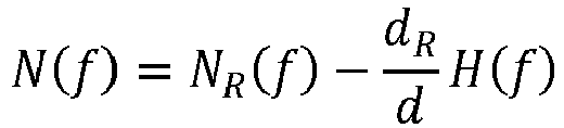
- Noise PSD at the ingress point is N(f), resulting in N R (f) on the remote side (left) and N O (f) on the operator's side (right).
- the cable transfer function (inverse of attenuation) is H(f), with H R (f) and H O (f) each for the two segments.
- figure 1 shows a scenario with a noise ingress point at distance d R from the remote (customer premises) side.
- distances are given in meters
- N O f N f + H O f
- H(f), H R (f), and H O (f) are normally negative dB values since the copper loop is passive and does not amplify the noise.
- the result may be expressed instead as a percentage of the loop length, which may still be useful.
- the noise source is located at the customer premises, there will be no need to book a visit to the customer's home and no need to ask the customer to look for potential noise sources in her home.
- an improved estimate of the position where the noise enters the line can be achieved by using more than one measurement. For example, a position estimate can be made for each frequency, and a further estimate generated as the average of those estimates.
- the invention may thus be embodied as a method in a system comprising a CPE 120, a transmission line 100, a DSLAM 110 and a device for operation and maintenance (O&M device) 150.
- the invention could also be embodied as a method in the CPE, the DSLAM or the O&M device. Further the invention could be embodied as a CPE, DSLAM or O&M device adapted to carry out the corresponding method.
- a step 1110 the noise level at a frequency or frequency band at the customer end of the line is measured by the CPE.
- the frequency or frequency band is within a transmit band of the CPE or the DSLAM.
- a step 1120 the measurement result is communicated over the line to the DSLAM in a step 1130 the result is further communicated to the O&M device.
- the noise level is measured at the same frequency or frequency band by the DSLAM at the central office end of the line.
- step 1150 the result from step 1140 is also communicated to the O&M device.
- a position where noise enters the line is estimated in dependence of the relationship between the noise levels. The estimate is made in the O&M device.
- steps 1130 and 1150 are not needed, or take place within the DSLAM.
- a method embodying the invention in a CPE is as follows.
- a noise measurement is made at a frequency or frequency band which is within a transmit band of the CPE.
- the result of the measurement is communicated over the line.
- the measurement may for example be communicated elsewhere, or in another way, or not communicated, e.g. if the measurement is only to be stored, or if it is to be used in the CPE.
- a method embodying the invention in a DSLAM is as follows
- a noise measurement is made at a frequency or frequency band which is within a transmit band of the DSLAM.
- a result of a noise measurement at a frequency or frequency band at the CPE end of the line made by the CPE is received via the line.
- the frequency or frequency band is within a transmit band of the CPE or the DSLAM.
- a result of a noise measurement at the same frequency or frequency band at the DSLAM end of the line made by the DSLAM is received.
- a step 1430 an estimate of the position where noise enters the line is made by the O&M device.
- step 1440 an estimate is made of the noise level at the point where noise enters the line.
- the O&M device 150 is typically a workstation or similar computer. There will be program code in the device for receiving a noise measurement result from the CPE. The result is typically sent from the CPE 120 to the DSLAM 110 over the line and then further to the device 150. There will also be code for receiving a measurement result from the DSLAM 110, and program code for generating an estimate of a position where noise enters the transmission line in dependence of the relationship between the first and the second noise level measurement results. There may also optionally be program code for estimating the noise level at the point where noise enters the line.
- the functions of the device 150 are integrated into the DSLAM 110.
- the CPE 120 may have program code for, or otherwise be configured to make noise level measurements in one or more of its transmit bands. Any filter through which the measurement is made should be properly applied, so that measurement is made in a pass band of the filter. There may also be program code for sending measurements results over the line.
- the DSLAM 110 may have program code for, or otherwise be configured to make noise level measurements in one or more of its transmit bands. Any filter through which the measurement is made should be properly applied, so that measurement is made in a pass band of the filter. There may also be program code for receiving measurement results from the CPE 120 as well as code for sending measurement results to the O&M device 150. The results may be from measurement in the DSLAM 110 or received from the CPE 120.
- the measurement is made through the receive band filter, and the transmit band tones are therefore outside of the filter pass band.
- the measured frequencies should fall within the pass band of the filter through which the measurement was made.
- the first solution is, at least in theory, straightforward but requires changes to existing standards, possibly leading to interoperability problems. Also, not all existing hardware can be adapted to measure on transmit bands. For example, typical ADSL2+ DSLAMs can only be made to measure (receive) on the first 64 (upstream) tones while they can be made to transmit on 512 tones. This situation improves with VDSL2 since a VDSL2 modem must support several different band plans, meaning that the hardware has to be more flexible and allow reception over wider frequency bands.
- the second solution is definitely feasible but also suffers from the same hardware limitation problem as the first solution. Further, with current standards, it will only support noise ingress localization in the downstream bands since no noise measurements will be available for the upstream bands in the CPE.
- the third solution allows noise localization on all subcarriers jointly supported by the transceivers but requires adapted SELT measurements both at the Central Office (CO) side and at the Customer Premises (CP) side.
- CO Central Office
- CP Customer Premises
- SELT is currently not yet standardized although a draft first version of the G.linetest (G.996.2) standard was consented by ITU-T SG15/Q4 in December 2008. Further, in the first draft, it is still not agreed on how to manage CPE SELT and how to get the measurement results communicated to the DSLAM side. However, it is expected that the standard will continue to evolve in the near future.
- number two has the advantage that it can be utilized without modifications to existing CPEs that supports Loop Diagnostics.
- the DSLAM should be adapted to support SELT noise measurements for the downstream (transmit) bands.
- the noise source should be dominant at both ends of the loop, i.e. the majority of the noise measured for a certain subcarrier must come from the same source at both ends of the loop.
- Figure 2 shows an experimental setup for measuring noise at operator (CO) side of the line.
- Figure 3 shows an experimental setup for measuring noise at remote (CP) side of the line.
- a VDSL2 DSLAM adapted to measure noise over the full band was used to measure the noise on both sides of a loop consisting of 200 + 500 meter of 0.4 mm telephone cable.
- the setup in figure 2 was used to measure the noise on the whole band for the CO side of the loop and secondly, since no suitably adapted CPE was available, the DSLAM was moved to the other end of the loop according to figure 3 in order to measure on the CP side. The latter is unrealistic in a real scenario but was done to visualize the great potential the noise localization method will have if the standards are evolved as discussed earlier.
- Additive White Gaussian Noise with a flat PSD level of -90 dBm/Hz has been injected 500 m from the CO side of a loop with a total length of 700 m.
- the noise injection point is thus located 200 m from the CP side of the loop.
- Figure 4 shows the received noise at both sides of the loop (NO(f) and NR(f)). Since the attenuation is higher for the longer side of the loop the received noise is weaker at the CO side than on the CP side.
- the cable attenuation at 1 MHz was known to be 20.5 dB/km.
- Equation (11) the estimated distance from each end of the loop to the noise injection point.
- the noise location is estimated to be very close to the true location of 200 m from the CP side and 500 m from the CO side.
- the error at high frequencies is because the noise was too much attenuated at the CO side for these frequencies so the injected noise was no longer dominant over the background noise when measured at the CO side.
- the noise graph flattens out at high frequencies.
- the ripple at low frequencies is caused by the noise injector used in the experiment.
- Equation (12) is used to calculate the PSD of the noise at the injection point as shown in figure 6 .
- the noise is supposed to be flat for the whole spectrum but once again the effect of the weak received noise signal at the CO side can be seen on high frequencies.
- the offset from -90 dBm/Hz at lower frequencies is likely a combination of measurement errors in the DSLAM, impedance mismatch and imperfect calibration of the noise generator and noise injection box.
- Figure 7 shows the measured noise on each side of the loop. Two RFI peaks at 10 and 15 MHz have been injected 500 m from the CO side. The measurements are marked with a circle for the CO side and an asterisk for the CPE side.
- Figure 8 shows the estimation of the RFI noise location.
- the peaks at 10 and 15 MHz are correctly estimated at about 500 m from the CO side.
- the noise at all other frequencies will be located in the middle of the loop i.e. at 350 m (assuming that the background noise has the same PSD at both sides of the loop).
- the deviation at low frequencies is probably caused by some other noise source in the laboratory, closer to the CP side of the loop.
- the location of the RFI peaks is correctly estimated at 500 m from the CO side.
- Figure 9 shows the estimated noise power at the source.
- the power at the noise source has been calculated from Equation (12).
- the graph shows a slope corresponding to the cable attenuation since it is assumed that the background noise origins from a source close to the middle of the cable.
- the RFI peaks are well estimated at approximately -60 dBm/Hz.
- the background noise is also used in the calculations of the noise power at the source.
- the background noise is therefore compensated for the attenuation from the end point of the loop to the noise injection point and hence the estimated noise graph at the noise source shows a slope corresponding to the attenuation.
- the noise PSD is low except for the RFI peaks and thus it is only the peaks in figure 9 that are of interest. These are correctly estimated to have a PSD of approximately -60 dBm/Hz.
- a very crude location estimate can be obtained already from measurement of the noise PSDs at both ends of a loop.
- Refined location estimates can be achieved by, in addition to the noise measurements, also utilizing loop length and attenuation information. This type of information can be estimated with good accuracy from SELT, DELT or similar methods.
Landscapes
- Engineering & Computer Science (AREA)
- Signal Processing (AREA)
- Computer Networks & Wireless Communication (AREA)
- Monitoring And Testing Of Transmission In General (AREA)
- Telephone Function (AREA)
- Data Exchanges In Wide-Area Networks (AREA)
Claims (17)
- Verfahren zum Schätzen einer Position, wo Rauschen in eine Telekommunikationsübertragungsleitung (100) eintritt,
wobei die Leitung erste DSL-Kommunikationsausrüstung (120) aufweist, die mit einem ersten Ende der Leitung verbunden ist, und zweite DSL-Kommunikationsausrüstung (110), die mit einem zweiten, gegenüberliegenden Ende der Leitung verbunden ist,
das Verfahren umfassend die folgenden Schritte
Empfangen (1410), über die Leitung, eines ersten Ergebnisses einer Messung eines Rauschpegels an dem ersten Ende der Übertragungsleitung, die durch die erste DSL-Ausrüstung vorgenommen wird,
Empfangen (1420) eines zweiten Ergebnisses einer Messung eines Rauschpegels an dem zweiten Ende der Übertragungsleitung, die durch die zweite DSL-Ausrüstung vorgenommen wird,
gekennzeichnet durch einen Schritt zum Erzeugen einer Schätzung (1160, 1430) einer Position, wo Rauschen in die Übertragungsleitung eintritt, abhängig von dem Verhältnis zwischen dem ersten und dem zweiten Rauschpegelmessergebnis, wo die erste und zweite Rauschpegelmessung bei derselben Frequenz oder demselben Frequenzband vorgenommen werden und die Frequenz oder das Frequenzband innerhalb eines Sendebands von mindestens einer der ersten und zweiten DSL-Ausrüstungen fällt, wobei das Verhältnis eine Differenz zwischen dem ersten und dem zweiten Rauschmessergebnis ist. - Verfahren nach Anspruch 1, wobei eine Positionsschätzung erzeugt wird als

- Verfahren nach einem der Ansprüche 1-2, wobei das Verfahren nach Anspruch 2 bei mehreren verschiedenen Frequenzen angewendet wird und eine Schätzung einer wahrscheinlichen Position aus den mehreren so erhaltenen Positionsschätzungen erzeugt wird.
- Verfahren nach einem der Ansprüche 1-3, weiter umfassend den Schritt zum Erzeugen (1440) einer Schätzung der Rauschleistungsspektralverteilung an der Position, wo Rauschen in die Leitung eintritt, abhängig von dem Verhältnis zwischen dem ersten und zweiten Rauschpegelmessergebnis.
- Verfahren nach Anspruch 4, wobei die Schätzung der Rauschleistungsspektralverteilung, PSD, als
- Verfahren nach einem der Ansprüche 1-5, wobei die erste DSL-Ausrüstung (120) eine xDSL CPE ist und/oder die zweite DSL-Ausrüstung (110) eine xDSL DSLAM ist.
- Vorrichtung (150) zum Schätzen einer Position, wo Rauschen in eine Telekommunikationsübertragungsleitung (100) eintritt,
wobei die Leitung erste DSL-Kommunikationsausrüstung (120) aufweist, die mit einem ersten Ende der Leitung verbunden ist, und zweite DSL-Kommunikationsausrüstung (110), die mit einem zweiten, gegenüberliegenden Ende der Leitung verbunden ist,
die Vorrichtung umfassend
Mittel zum Empfangen, über die Leitung, eines ersten Ergebnisses einer Messung eines Rauschpegels an dem ersten Ende der Übertragungsleitung, die durch die erste DSL-Ausrüstung vorgenommen wird, und
Mittel zum Empfangen eines zweiten Ergebnisses einer Messung eines Rauschpegels an dem zweiten Ende der Übertragungsleitung, die durch die zweite DSL-Ausrüstung vorgenommen wird,
gekennzeichnet durch Mittel zum Erzeugen einer Schätzung (1160, 1440) einer Position, wo Rauschen in die Übertragungsleitung eintritt, abhängig von dem Verhältnis zwischen dem ersten und dem zweiten Rauschpegelmessergebnis, wo die erste und zweite Rauschpegelmessung bei derselben Frequenz oder demselben Frequenzband vorgenommen werden und die Frequenz oder das Frequenzband innerhalb eines Sendebands von mindestens einer der ersten und zweiten DSL-Ausrüstungen fällt, wobei das Verhältnis eine Differenz zwischen dem ersten und dem zweiten Rauschmessergebnis ist. - Vorrichtung nach Anspruch 7, weiter aufweisend Mittel zum Erzeugen einer Schätzung der Rauschleistungsspektralverteilung an der Position, wo Rauschen in die Leitung eintritt, abhängig von dem Verhältnis zwischen dem ersten und dem zweiten Rauschpegelmessergebnis.
- DSL-Kommunikationsausrüstung (110,120), angepasst zur Verwendung mit dem Verfahren nach Anspruch 1, indem sie zum Messen von Rauschen einer ruhigen Leitung, QLN, in mindestens einem ihrer Sendebänder angepasst ist.
- Ausrüstung nach Anspruch 9, die zum Messen von QLN bei allen Frequenzen angepasst ist, die zum Empfangen oder Übertragen von Daten verwendet werden.
- Ausrüstung nach Anspruch 9-10, wobei die Ausrüstung eine xDSL CPE (120) oder eine xDSL DSLAM (110) ist.
- Ausrüstung nach Anspruch 11, wobei xDSL VDSL2 ist.
- Ausrüstung nach einem der Ansprüche 9-12, die angepasst ist, die Sendeband-QLN-Messung in dem Durchlassband jedes Filters vorzunehmen, durch den die Messung vorgenommen wird.
- Verfahren, umfassend den Schritt zum Messen (1210; 1310) durch eine DSL-Kommunikationsausrüstung (120,110) nach einem der Ansprüche 9-13, von QLN in mindestens einem der Sendebänder der Ausrüstung.
- Verfahren nach Anspruch 14, wobei QLN bei allen Frequenzen gemessen wird, die zum Empfangen oder Übertragen von Daten verwendet werden.
- Verfahren nach einem der Ansprüche 14-15, wobei die Sendeband-QLN-Messung in dem Durchlassband jedes Filters vorgenommen wird, durch den die Messung vorgenommen wird.
- Verfahren zum Schätzen einer Position, wo Rauschen in eine Telekommunikationsübertragungsleitung (100) eintritt,
umfassend die folgenden Schritte
Messen (1110) eines ersten Rauschpegels bei einer ersten Frequenz oder einem ersten Frequenzband an einem ersten Ende der Übertragungsleitung durch eine DSL CPE (120) und Kommunizieren (1120) desselben über die Leitung zu einem DSLAM (110) am gegenüberliegenden Ende,
Messen (1140) eines zweiten Rauschpegels bei der ersten Frequenz oder dem ersten Frequenzband an einem gegenüberliegenden Ende der Übertragungsleitung durch den DSLAM,
gekennzeichnet durch einen Schritt zum
Schätzen (1160, 1440), abhängig von dem Verhältnis zwischen dem ersten und zweiten Rauschpegel, der Position, wo Rausch in die Übertragungsleitung eintritt,
wobei die Frequenz oder das Frequenzband innerhalb eines Sendebands von mindestens einem der CPE und des DSLAM fällt und wobei das Verhältnis eine Differenz zwischen dem ersten und dem zweiten Rauschmessergebnis ist.
Applications Claiming Priority (2)
| Application Number | Priority Date | Filing Date | Title |
|---|---|---|---|
| US15171409P | 2009-02-11 | 2009-02-11 | |
| PCT/SE2009/050474 WO2010093300A1 (en) | 2009-02-11 | 2009-04-30 | Methods and devices for transmission line analysis |
Publications (3)
| Publication Number | Publication Date |
|---|---|
| EP2396959A1 EP2396959A1 (de) | 2011-12-21 |
| EP2396959A4 EP2396959A4 (de) | 2016-08-10 |
| EP2396959B1 true EP2396959B1 (de) | 2020-08-12 |
Family
ID=42561966
Family Applications (1)
| Application Number | Title | Priority Date | Filing Date |
|---|---|---|---|
| EP09840124.3A Not-in-force EP2396959B1 (de) | 2009-02-11 | 2009-04-30 | Verfahren und vorrichtungen zur übertragungsleitungsanalyse |
Country Status (4)
| Country | Link |
|---|---|
| US (2) | US8767809B2 (de) |
| EP (1) | EP2396959B1 (de) |
| JP (1) | JP5220928B2 (de) |
| WO (1) | WO2010093300A1 (de) |
Families Citing this family (8)
| Publication number | Priority date | Publication date | Assignee | Title |
|---|---|---|---|---|
| EP2575335A1 (de) * | 2011-09-30 | 2013-04-03 | Alcatel Lucent | Diagnosemaschine |
| EP2615813B1 (de) * | 2012-01-10 | 2017-08-30 | Alcatel Lucent | Verfahren und Vorrichtung zur Identifikation einer Beeinträchtigung innerhalb einer Telekommunikationsleitung |
| US9148199B2 (en) * | 2013-04-01 | 2015-09-29 | Fluke Corporation | Prequalification of vectoring before implementation |
| US10911602B2 (en) | 2014-03-31 | 2021-02-02 | British Telecommunications Public Limited Company | Data communication |
| EP3451642B1 (de) * | 2017-09-01 | 2020-10-21 | Nokia Solutions and Networks Oy | Verfahren und netzwerkanalysator zur bewertung einer kommunikationsleitung |
| CN114557070A (zh) * | 2019-11-20 | 2022-05-27 | 华为技术有限公司 | 两级控制信道发送方法、终端设备及通信装置 |
| GB202103204D0 (en) | 2021-03-08 | 2021-04-21 | British Telecomm | Dsl fault location |
| US12411163B2 (en) | 2023-04-20 | 2025-09-09 | Rohde & Schwarz Gmbh & Co. Kg | Method and system for inline calibration of multiple radio frequency signals fed to the same device under test |
Family Cites Families (22)
| Publication number | Priority date | Publication date | Assignee | Title |
|---|---|---|---|---|
| EP2267914A3 (de) * | 2000-01-07 | 2012-09-26 | Aware, Inc. | Verfahren und Vorrichtung zur Bestimmung der Leitungslänge und der Brückenabgrifflänge in einer Übertragungsleitung |
| CA2297871C (en) | 2000-02-03 | 2004-12-28 | Consultronics Limited | Dmt test method for determining adsl capability of cables |
| US6341159B1 (en) | 2000-02-18 | 2002-01-22 | Harris Corporation | Extrapolation of location and amplitude of noise sources on telecommunication wireline from ended access point |
| US7116760B2 (en) * | 2000-12-04 | 2006-10-03 | Acterna, L.L.C. | System and method for single-ended line analysis for qualification and mapping |
| CA2441954A1 (en) * | 2001-04-26 | 2002-11-07 | Aware, Inc. | Systems and methods for loop characterization from double-ended measurements |
| US6725176B1 (en) | 2001-08-03 | 2004-04-20 | Centilliune Communications, Inc. | Loop diagnostics for ADSL systems |
| EP1349355A1 (de) * | 2002-03-28 | 2003-10-01 | BRITISH TELECOMMUNICATIONS public limited company | Verfahren und Vorrichtung zur Fehlererkennung für eine Fernsprechleitung |
| US7023963B1 (en) * | 2002-09-18 | 2006-04-04 | Adtran, Inc. | DSL line card echo canceler-based mechanism for locating telecommunication line fault |
| US20070022331A1 (en) * | 2002-12-09 | 2007-01-25 | Covaro Networks, Inc. | Single-ended ethernet management system and method |
| US6822457B2 (en) * | 2003-03-27 | 2004-11-23 | Marshall B. Borchert | Method of precisely determining the location of a fault on an electrical transmission system |
| US20050036560A1 (en) * | 2003-08-14 | 2005-02-17 | Adc Dsl Systems, Inc. | Cable calculator |
| US7400150B2 (en) * | 2004-08-05 | 2008-07-15 | Cannon Technologies, Inc. | Remote fault monitoring in power lines |
| US8130911B2 (en) | 2004-12-01 | 2012-03-06 | Telefonaktiebolaget Lm Ericsson (Publ) | Characteristics determination of a digital subscriber line |
| ATE470289T1 (de) * | 2005-03-04 | 2010-06-15 | Alcatel Lucent | Verfahren und vorrichtung zur lokalisierung der innerbetrieblichen verdrahtungdefekte |
| US7623630B2 (en) * | 2005-04-08 | 2009-11-24 | Ikanos Communications, Inc. | Double-ended line probing (DELP) for DSL systems |
| CN1870611A (zh) * | 2005-05-26 | 2006-11-29 | 华为技术有限公司 | 估算信道性能参数的方法及系统 |
| EP1801994A1 (de) * | 2005-12-23 | 2007-06-27 | Alcatel Lucent | System zum Prüfen von ADSL Netwerken |
| US8270311B2 (en) * | 2006-09-05 | 2012-09-18 | Telefonaktiebolaget Lm Ericsson (Publ) | Method for determining automatically a FEXT/NEXT transfer-function |
| EP2214390B1 (de) * | 2009-01-30 | 2013-01-09 | Alcatel Lucent | Verfahren zur Standortbestimmung eines Defekts in einer Drahtübertragungsleitung und Systeme gemäß solcher Verfahren |
| US8874391B2 (en) * | 2009-06-05 | 2014-10-28 | Bae Systems Information And Electronic Systems Integration Inc. | Distance-to-fault measurement system capable of measuring complex reflection coefficients |
| EP2615813B1 (de) * | 2012-01-10 | 2017-08-30 | Alcatel Lucent | Verfahren und Vorrichtung zur Identifikation einer Beeinträchtigung innerhalb einer Telekommunikationsleitung |
| JP2015515784A (ja) * | 2012-03-12 | 2015-05-28 | アダプティブ スペクトラム アンド シグナル アラインメント インコーポレイテッド | ネットワークインターフェース装置に対する回線マイクロフィルタ状態の特性化及び回線故障の位置決めのための方法及びシステム |
-
2009
- 2009-04-30 EP EP09840124.3A patent/EP2396959B1/de not_active Not-in-force
- 2009-04-30 WO PCT/SE2009/050474 patent/WO2010093300A1/en not_active Ceased
- 2009-04-30 US US13/148,550 patent/US8767809B2/en active Active
- 2009-04-30 JP JP2011549114A patent/JP5220928B2/ja not_active Expired - Fee Related
-
2014
- 2014-05-29 US US14/290,020 patent/US9246614B2/en active Active
Non-Patent Citations (1)
| Title |
|---|
| None * |
Also Published As
| Publication number | Publication date |
|---|---|
| US9246614B2 (en) | 2016-01-26 |
| US8767809B2 (en) | 2014-07-01 |
| WO2010093300A1 (en) | 2010-08-19 |
| JP2012517733A (ja) | 2012-08-02 |
| JP5220928B2 (ja) | 2013-06-26 |
| US20140313919A1 (en) | 2014-10-23 |
| US20120020398A1 (en) | 2012-01-26 |
| EP2396959A4 (de) | 2016-08-10 |
| EP2396959A1 (de) | 2011-12-21 |
Similar Documents
| Publication | Publication Date | Title |
|---|---|---|
| US9246614B2 (en) | Methods and devices for transmission line analysis | |
| US8687770B2 (en) | Systems and methods for performing line imbalance measurement and mitigation based on a common mode sensor | |
| EP2153537B1 (de) | Verfahren und vorrichtung zur übersprechungsbeurteilung und kommunikationssystem mit einer derartigen vorrichtung | |
| EP2060013B1 (de) | Verfahren zum automatischen bestimmen einer fext/next-übertragungsfunktion | |
| EP2464089A1 (de) | Diagnosemaschine zur Bestimmung der umfassenden Leitungseigenschaften einer DSL-Telekommunikationsleitung und Verfahren damit | |
| EP2550752A1 (de) | Schätzung eines paarsymmetriestatus für eine kommunikationsleitung | |
| US8331537B2 (en) | Method and system for managing line topology | |
| CN102232271A (zh) | 用于传送线路分析的方法 | |
| CN101908909A (zh) | 估计远端串扰信道的方法和装置 | |
| EP1672809B1 (de) | Verfahren und Apparat für die Bestimmung der Sender-PSD an einer entfernten Au enstelle | |
| EP3041151B1 (de) | Verfahren, vorrichtung und system zur erkennung einer störenden leitung | |
| EP2451121A1 (de) | Verfahren und system zur voreinschätzung der maximalen bandbreite einer teilnehmerleitung in einer digitalen teilnehmerschleife | |
| US9564946B2 (en) | Methods and apparatuses for characterizing common mode noise and estimating loop imbalance | |
| US11411606B2 (en) | Method and system for estimating crosstalk between electrical transmission lines | |
| US9426268B2 (en) | Method and apparatus for gauge identification based on single ended line testing (SELT) | |
| CN105340188A (zh) | 用于检测电力线系统在双绞线上引起的噪声的方法 | |
| Wia | Loop Qualification for xDSL | |
| Nilsson | Management of a DSL copper network using built-in loop qualification tools | |
| Rongpeng et al. | Single-Ended Loop Testing (SELT)-New Architecture |
Legal Events
| Date | Code | Title | Description |
|---|---|---|---|
| PUAI | Public reference made under article 153(3) epc to a published international application that has entered the european phase |
Free format text: ORIGINAL CODE: 0009012 |
|
| 17P | Request for examination filed |
Effective date: 20110729 |
|
| AK | Designated contracting states |
Kind code of ref document: A1 Designated state(s): AT BE BG CH CY CZ DE DK EE ES FI FR GB GR HR HU IE IS IT LI LT LU LV MC MK MT NL NO PL PT RO SE SI SK TR |
|
| DAX | Request for extension of the european patent (deleted) | ||
| RA4 | Supplementary search report drawn up and despatched (corrected) |
Effective date: 20160707 |
|
| RIC1 | Information provided on ipc code assigned before grant |
Ipc: H04M 3/46 20060101ALI20160701BHEP Ipc: H04M 3/30 20060101AFI20160701BHEP Ipc: H04M 11/06 20060101ALI20160701BHEP |
|
| STAA | Information on the status of an ep patent application or granted ep patent |
Free format text: STATUS: EXAMINATION IS IN PROGRESS |
|
| 17Q | First examination report despatched |
Effective date: 20190920 |
|
| REG | Reference to a national code |
Ref country code: DE Ref legal event code: R079 Ref document number: 602009062611 Country of ref document: DE Free format text: PREVIOUS MAIN CLASS: H04M0003300000 Ipc: H04M0011060000 |
|
| GRAP | Despatch of communication of intention to grant a patent |
Free format text: ORIGINAL CODE: EPIDOSNIGR1 |
|
| STAA | Information on the status of an ep patent application or granted ep patent |
Free format text: STATUS: GRANT OF PATENT IS INTENDED |
|
| RIC1 | Information provided on ipc code assigned before grant |
Ipc: H04M 11/06 20060101AFI20200122BHEP Ipc: H04B 3/46 20150101ALI20200122BHEP Ipc: H04M 3/30 20060101ALI20200122BHEP |
|
| INTG | Intention to grant announced |
Effective date: 20200213 |
|
| GRAJ | Information related to disapproval of communication of intention to grant by the applicant or resumption of examination proceedings by the epo deleted |
Free format text: ORIGINAL CODE: EPIDOSDIGR1 |
|
| STAA | Information on the status of an ep patent application or granted ep patent |
Free format text: STATUS: EXAMINATION IS IN PROGRESS |
|
| GRAJ | Information related to disapproval of communication of intention to grant by the applicant or resumption of examination proceedings by the epo deleted |
Free format text: ORIGINAL CODE: EPIDOSDIGR1 |
|
| GRAP | Despatch of communication of intention to grant a patent |
Free format text: ORIGINAL CODE: EPIDOSNIGR1 |
|
| GRAS | Grant fee paid |
Free format text: ORIGINAL CODE: EPIDOSNIGR3 |
|
| INTC | Intention to grant announced (deleted) | ||
| GRAR | Information related to intention to grant a patent recorded |
Free format text: ORIGINAL CODE: EPIDOSNIGR71 |
|
| GRAS | Grant fee paid |
Free format text: ORIGINAL CODE: EPIDOSNIGR3 |
|
| STAA | Information on the status of an ep patent application or granted ep patent |
Free format text: STATUS: GRANT OF PATENT IS INTENDED |
|
| GRAA | (expected) grant |
Free format text: ORIGINAL CODE: 0009210 |
|
| STAA | Information on the status of an ep patent application or granted ep patent |
Free format text: STATUS: THE PATENT HAS BEEN GRANTED |
|
| AK | Designated contracting states |
Kind code of ref document: B1 Designated state(s): AT BE BG CH CY CZ DE DK EE ES FI FR GB GR HR HU IE IS IT LI LT LU LV MC MK MT NL NO PL PT RO SE SI SK TR |
|
| INTG | Intention to grant announced |
Effective date: 20200707 |
|
| REG | Reference to a national code |
Ref country code: GB Ref legal event code: FG4D |
|
| REG | Reference to a national code |
Ref country code: CH Ref legal event code: EP |
|
| REG | Reference to a national code |
Ref country code: DE Ref legal event code: R096 Ref document number: 602009062611 Country of ref document: DE |
|
| REG | Reference to a national code |
Ref country code: IE Ref legal event code: FG4D |
|
| REG | Reference to a national code |
Ref country code: AT Ref legal event code: REF Ref document number: 1302705 Country of ref document: AT Kind code of ref document: T Effective date: 20200915 |
|
| REG | Reference to a national code |
Ref country code: LT Ref legal event code: MG4D |
|
| REG | Reference to a national code |
Ref country code: NL Ref legal event code: MP Effective date: 20200812 |
|
| PG25 | Lapsed in a contracting state [announced via postgrant information from national office to epo] |
Ref country code: FI Free format text: LAPSE BECAUSE OF FAILURE TO SUBMIT A TRANSLATION OF THE DESCRIPTION OR TO PAY THE FEE WITHIN THE PRESCRIBED TIME-LIMIT Effective date: 20200812 Ref country code: HR Free format text: LAPSE BECAUSE OF FAILURE TO SUBMIT A TRANSLATION OF THE DESCRIPTION OR TO PAY THE FEE WITHIN THE PRESCRIBED TIME-LIMIT Effective date: 20200812 Ref country code: SE Free format text: LAPSE BECAUSE OF FAILURE TO SUBMIT A TRANSLATION OF THE DESCRIPTION OR TO PAY THE FEE WITHIN THE PRESCRIBED TIME-LIMIT Effective date: 20200812 Ref country code: BG Free format text: LAPSE BECAUSE OF FAILURE TO SUBMIT A TRANSLATION OF THE DESCRIPTION OR TO PAY THE FEE WITHIN THE PRESCRIBED TIME-LIMIT Effective date: 20201112 Ref country code: GR Free format text: LAPSE BECAUSE OF FAILURE TO SUBMIT A TRANSLATION OF THE DESCRIPTION OR TO PAY THE FEE WITHIN THE PRESCRIBED TIME-LIMIT Effective date: 20201113 Ref country code: ES Free format text: LAPSE BECAUSE OF FAILURE TO SUBMIT A TRANSLATION OF THE DESCRIPTION OR TO PAY THE FEE WITHIN THE PRESCRIBED TIME-LIMIT Effective date: 20200812 Ref country code: LT Free format text: LAPSE BECAUSE OF FAILURE TO SUBMIT A TRANSLATION OF THE DESCRIPTION OR TO PAY THE FEE WITHIN THE PRESCRIBED TIME-LIMIT Effective date: 20200812 Ref country code: NO Free format text: LAPSE BECAUSE OF FAILURE TO SUBMIT A TRANSLATION OF THE DESCRIPTION OR TO PAY THE FEE WITHIN THE PRESCRIBED TIME-LIMIT Effective date: 20201112 |
|
| REG | Reference to a national code |
Ref country code: AT Ref legal event code: MK05 Ref document number: 1302705 Country of ref document: AT Kind code of ref document: T Effective date: 20200812 |
|
| PG25 | Lapsed in a contracting state [announced via postgrant information from national office to epo] |
Ref country code: NL Free format text: LAPSE BECAUSE OF FAILURE TO SUBMIT A TRANSLATION OF THE DESCRIPTION OR TO PAY THE FEE WITHIN THE PRESCRIBED TIME-LIMIT Effective date: 20200812 Ref country code: LV Free format text: LAPSE BECAUSE OF FAILURE TO SUBMIT A TRANSLATION OF THE DESCRIPTION OR TO PAY THE FEE WITHIN THE PRESCRIBED TIME-LIMIT Effective date: 20200812 Ref country code: PL Free format text: LAPSE BECAUSE OF FAILURE TO SUBMIT A TRANSLATION OF THE DESCRIPTION OR TO PAY THE FEE WITHIN THE PRESCRIBED TIME-LIMIT Effective date: 20200812 Ref country code: IS Free format text: LAPSE BECAUSE OF FAILURE TO SUBMIT A TRANSLATION OF THE DESCRIPTION OR TO PAY THE FEE WITHIN THE PRESCRIBED TIME-LIMIT Effective date: 20201212 |
|
| PG25 | Lapsed in a contracting state [announced via postgrant information from national office to epo] |
Ref country code: CZ Free format text: LAPSE BECAUSE OF FAILURE TO SUBMIT A TRANSLATION OF THE DESCRIPTION OR TO PAY THE FEE WITHIN THE PRESCRIBED TIME-LIMIT Effective date: 20200812 Ref country code: EE Free format text: LAPSE BECAUSE OF FAILURE TO SUBMIT A TRANSLATION OF THE DESCRIPTION OR TO PAY THE FEE WITHIN THE PRESCRIBED TIME-LIMIT Effective date: 20200812 Ref country code: DK Free format text: LAPSE BECAUSE OF FAILURE TO SUBMIT A TRANSLATION OF THE DESCRIPTION OR TO PAY THE FEE WITHIN THE PRESCRIBED TIME-LIMIT Effective date: 20200812 Ref country code: RO Free format text: LAPSE BECAUSE OF FAILURE TO SUBMIT A TRANSLATION OF THE DESCRIPTION OR TO PAY THE FEE WITHIN THE PRESCRIBED TIME-LIMIT Effective date: 20200812 |
|
| REG | Reference to a national code |
Ref country code: DE Ref legal event code: R097 Ref document number: 602009062611 Country of ref document: DE |
|
| PG25 | Lapsed in a contracting state [announced via postgrant information from national office to epo] |
Ref country code: AT Free format text: LAPSE BECAUSE OF FAILURE TO SUBMIT A TRANSLATION OF THE DESCRIPTION OR TO PAY THE FEE WITHIN THE PRESCRIBED TIME-LIMIT Effective date: 20200812 |
|
| PLBE | No opposition filed within time limit |
Free format text: ORIGINAL CODE: 0009261 |
|
| STAA | Information on the status of an ep patent application or granted ep patent |
Free format text: STATUS: NO OPPOSITION FILED WITHIN TIME LIMIT |
|
| PG25 | Lapsed in a contracting state [announced via postgrant information from national office to epo] |
Ref country code: SK Free format text: LAPSE BECAUSE OF FAILURE TO SUBMIT A TRANSLATION OF THE DESCRIPTION OR TO PAY THE FEE WITHIN THE PRESCRIBED TIME-LIMIT Effective date: 20200812 |
|
| 26N | No opposition filed |
Effective date: 20210514 |
|
| PG25 | Lapsed in a contracting state [announced via postgrant information from national office to epo] |
Ref country code: IT Free format text: LAPSE BECAUSE OF FAILURE TO SUBMIT A TRANSLATION OF THE DESCRIPTION OR TO PAY THE FEE WITHIN THE PRESCRIBED TIME-LIMIT Effective date: 20200812 |
|
| PG25 | Lapsed in a contracting state [announced via postgrant information from national office to epo] |
Ref country code: SI Free format text: LAPSE BECAUSE OF FAILURE TO SUBMIT A TRANSLATION OF THE DESCRIPTION OR TO PAY THE FEE WITHIN THE PRESCRIBED TIME-LIMIT Effective date: 20200812 |
|
| PG25 | Lapsed in a contracting state [announced via postgrant information from national office to epo] |
Ref country code: MC Free format text: LAPSE BECAUSE OF FAILURE TO SUBMIT A TRANSLATION OF THE DESCRIPTION OR TO PAY THE FEE WITHIN THE PRESCRIBED TIME-LIMIT Effective date: 20200812 |
|
| PG25 | Lapsed in a contracting state [announced via postgrant information from national office to epo] |
Ref country code: LU Free format text: LAPSE BECAUSE OF NON-PAYMENT OF DUE FEES Effective date: 20210430 |
|
| REG | Reference to a national code |
Ref country code: BE Ref legal event code: MM Effective date: 20210430 |
|
| PG25 | Lapsed in a contracting state [announced via postgrant information from national office to epo] |
Ref country code: FR Free format text: LAPSE BECAUSE OF NON-PAYMENT OF DUE FEES Effective date: 20210430 Ref country code: CH Free format text: LAPSE BECAUSE OF NON-PAYMENT OF DUE FEES Effective date: 20210430 Ref country code: LI Free format text: LAPSE BECAUSE OF NON-PAYMENT OF DUE FEES Effective date: 20210430 |
|
| PG25 | Lapsed in a contracting state [announced via postgrant information from national office to epo] |
Ref country code: IE Free format text: LAPSE BECAUSE OF NON-PAYMENT OF DUE FEES Effective date: 20210430 |
|
| PG25 | Lapsed in a contracting state [announced via postgrant information from national office to epo] |
Ref country code: IS Free format text: LAPSE BECAUSE OF FAILURE TO SUBMIT A TRANSLATION OF THE DESCRIPTION OR TO PAY THE FEE WITHIN THE PRESCRIBED TIME-LIMIT Effective date: 20201212 |
|
| PG25 | Lapsed in a contracting state [announced via postgrant information from national office to epo] |
Ref country code: BE Free format text: LAPSE BECAUSE OF NON-PAYMENT OF DUE FEES Effective date: 20210430 |
|
| PG25 | Lapsed in a contracting state [announced via postgrant information from national office to epo] |
Ref country code: PT Free format text: LAPSE BECAUSE OF FAILURE TO SUBMIT A TRANSLATION OF THE DESCRIPTION OR TO PAY THE FEE WITHIN THE PRESCRIBED TIME-LIMIT Effective date: 20201214 |
|
| PG25 | Lapsed in a contracting state [announced via postgrant information from national office to epo] |
Ref country code: HU Free format text: LAPSE BECAUSE OF FAILURE TO SUBMIT A TRANSLATION OF THE DESCRIPTION OR TO PAY THE FEE WITHIN THE PRESCRIBED TIME-LIMIT; INVALID AB INITIO Effective date: 20090430 Ref country code: CY Free format text: LAPSE BECAUSE OF FAILURE TO SUBMIT A TRANSLATION OF THE DESCRIPTION OR TO PAY THE FEE WITHIN THE PRESCRIBED TIME-LIMIT Effective date: 20200812 |
|
| PGFP | Annual fee paid to national office [announced via postgrant information from national office to epo] |
Ref country code: DE Payment date: 20230427 Year of fee payment: 15 |
|
| PGFP | Annual fee paid to national office [announced via postgrant information from national office to epo] |
Ref country code: GB Payment date: 20230427 Year of fee payment: 15 |
|
| PG25 | Lapsed in a contracting state [announced via postgrant information from national office to epo] |
Ref country code: MK Free format text: LAPSE BECAUSE OF FAILURE TO SUBMIT A TRANSLATION OF THE DESCRIPTION OR TO PAY THE FEE WITHIN THE PRESCRIBED TIME-LIMIT Effective date: 20200812 |
|
| PG25 | Lapsed in a contracting state [announced via postgrant information from national office to epo] |
Ref country code: TR Free format text: LAPSE BECAUSE OF FAILURE TO SUBMIT A TRANSLATION OF THE DESCRIPTION OR TO PAY THE FEE WITHIN THE PRESCRIBED TIME-LIMIT Effective date: 20200812 |
|
| PG25 | Lapsed in a contracting state [announced via postgrant information from national office to epo] |
Ref country code: MT Free format text: LAPSE BECAUSE OF FAILURE TO SUBMIT A TRANSLATION OF THE DESCRIPTION OR TO PAY THE FEE WITHIN THE PRESCRIBED TIME-LIMIT Effective date: 20200812 |
|
| REG | Reference to a national code |
Ref country code: DE Ref legal event code: R119 Ref document number: 602009062611 Country of ref document: DE |
|
| GBPC | Gb: european patent ceased through non-payment of renewal fee |
Effective date: 20240430 |
|
| PG25 | Lapsed in a contracting state [announced via postgrant information from national office to epo] |
Ref country code: DE Free format text: LAPSE BECAUSE OF NON-PAYMENT OF DUE FEES Effective date: 20241105 |
|
| PG25 | Lapsed in a contracting state [announced via postgrant information from national office to epo] |
Ref country code: GB Free format text: LAPSE BECAUSE OF NON-PAYMENT OF DUE FEES Effective date: 20240430 |
|
| PG25 | Lapsed in a contracting state [announced via postgrant information from national office to epo] |
Ref country code: GB Free format text: LAPSE BECAUSE OF NON-PAYMENT OF DUE FEES Effective date: 20240430 Ref country code: DE Free format text: LAPSE BECAUSE OF NON-PAYMENT OF DUE FEES Effective date: 20241105 |