EP2396767B1 - Verfahren und systeme zur bestimmung der position einer kamera hinsichtlich mindestens eines objekts einer echten umgebung - Google Patents
Verfahren und systeme zur bestimmung der position einer kamera hinsichtlich mindestens eines objekts einer echten umgebung Download PDFInfo
- Publication number
- EP2396767B1 EP2396767B1 EP10713797.8A EP10713797A EP2396767B1 EP 2396767 B1 EP2396767 B1 EP 2396767B1 EP 10713797 A EP10713797 A EP 10713797A EP 2396767 B1 EP2396767 B1 EP 2396767B1
- Authority
- EP
- European Patent Office
- Prior art keywords
- image
- camera
- reference model
- virtual reference
- coordinate system
- Prior art date
- Legal status (The legal status is an assumption and is not a legal conclusion. Google has not performed a legal analysis and makes no representation as to the accuracy of the status listed.)
- Active
Links
Images


Classifications
-
- G—PHYSICS
- G06—COMPUTING OR CALCULATING; COUNTING
- G06T—IMAGE DATA PROCESSING OR GENERATION, IN GENERAL
- G06T19/00—Manipulating three-dimensional [3D] models or images for computer graphics
- G06T19/006—Mixed reality
-
- G—PHYSICS
- G06—COMPUTING OR CALCULATING; COUNTING
- G06T—IMAGE DATA PROCESSING OR GENERATION, IN GENERAL
- G06T15/00—Three-dimensional [3D] image rendering
-
- G—PHYSICS
- G06—COMPUTING OR CALCULATING; COUNTING
- G06T—IMAGE DATA PROCESSING OR GENERATION, IN GENERAL
- G06T7/00—Image analysis
- G06T7/70—Determining position or orientation of objects or cameras
- G06T7/73—Determining position or orientation of objects or cameras using feature-based methods
- G06T7/75—Determining position or orientation of objects or cameras using feature-based methods involving models
-
- H—ELECTRICITY
- H04—ELECTRIC COMMUNICATION TECHNIQUE
- H04N—PICTORIAL COMMUNICATION, e.g. TELEVISION
- H04N5/00—Details of television systems
- H04N5/222—Studio circuitry; Studio devices; Studio equipment
- H04N5/2224—Studio circuitry; Studio devices; Studio equipment related to virtual studio applications
-
- G—PHYSICS
- G06—COMPUTING OR CALCULATING; COUNTING
- G06T—IMAGE DATA PROCESSING OR GENERATION, IN GENERAL
- G06T2207/00—Indexing scheme for image analysis or image enhancement
- G06T2207/20—Special algorithmic details
- G06T2207/20092—Interactive image processing based on input by user
-
- G—PHYSICS
- G06—COMPUTING OR CALCULATING; COUNTING
- G06T—IMAGE DATA PROCESSING OR GENERATION, IN GENERAL
- G06T2207/00—Indexing scheme for image analysis or image enhancement
- G06T2207/30—Subject of image; Context of image processing
- G06T2207/30244—Camera pose
-
- G—PHYSICS
- G06—COMPUTING OR CALCULATING; COUNTING
- G06T—IMAGE DATA PROCESSING OR GENERATION, IN GENERAL
- G06T2210/00—Indexing scheme for image generation or computer graphics
- G06T2210/04—Architectural design, interior design
Definitions
- the invention is directed to methods and systems for determining the pose of a camera with respect to at least one object of a real environment for use in an authoring, e.g. for geospatial databases, or augmented reality application, wherein at least one or two images are generated by the camera capturing a real object of a real environment.
- the image or images may by augmented with virtual objects according to the authoring or augmented reality technology.
- a camera coupled to a processing unit such as a microprocessor takes a picture of a real environment, wherein the real environment is displayed on a display screen and virtual objects may be displayed in addition to the real environment, so that the real environment displayed on the display screen is augmented with virtual objects of any kind on a display screen.
- a processing unit such as a microprocessor
- the microprocessor in order to augment the image with virtual objects, there is the need for the microprocessor to determine the position and orientation (so-called pose) of the camera with respect to at least one object of the real environment in order for the microprocessor to correctly augment the captured image with any virtual objects.
- correctly augmenting the captured image with any virtual objects means that the virtual objects are displayed in a manner that the virtual objects fit in a perspectively and dimensionally correct fashion into the scene of the image.
- a known method for determining the pose of the camera uses a virtual reference model of a corresponding part of the real environment captured by the camera, wherein the virtual reference model is projected into the image, using an initially known approximation of the pose, and superimposed with the corresponding part of the real environment.
- a tracking algorithm of the image processing uses the virtual reference model to determine the pose of the camera with respect to the real environment, for example by feature detection and comparison between the reference model and the corresponding part of the real environment.
- Another known method for determining the pose of the camera uses a marker that is placed in the real environment and captured by the camera when taking the image.
- a tracking algorithm of the image processing uses the marker to determine the pose of the camera with respect to the real environment, particularly by analysing of the marker in the image using known image processing methods.
- a disadvantage of the above-mentioned methods is that either a virtual reference model has to be conceived first and stored, which is very time and resource consuming and almost impossible if the AR technology shall be capable of being used spontaneously in any real environment.
- the user With respect to using a marker, the user has to place in an initial step the marker in the real environment before taking the image, which is also time consuming and troublesome.
- these methods may hardly be used in connection with any consumer products, such as mobile phones having an integrated camera and display, or other mobile devices.
- SLAM structure from motion and simultaneous localization and tracking
- All these methods serve for determining the position and orientation (pose) of a camera in relation to the real world or of part of the real world. If there is no pre-information available, in some cases it is not possible to determine the absolute pose of the camera in relation to the real world or part of the real world, but only the changes of the camera poses from a particular point of time.
- SLAM methods may be used to get orientation from planar points, but a disadvantage is that one is not sure if ground plane or some other plane is identified. Further, with such methods one may only get an initial scale by translating the camera, e.g. along a distance of 10 cm, and communicating the covered distance to the system.
- SLAM methods need at least two images (so-called frames) taken at different camera poses, and a calibrated camera.
- Lobo et al "Vision and Inertial Sensor Cooperation Using Gravity as a Vertical Reference", IEEE Transactions on Pattern Analysis and Machine Intelligence, IEEE Service Center, Vol. 25, No. 12, December 2003 , discloses a method using inertial sensor data in vision systems in mobile robotic systems. The pose and motion parameters are measured directly by the inertial sensors and combined with motion parameters determined from the image flow and known scene features. In 4.6 and 5.1 it is explained that in order to determine the system height and distance for initialization, a stereo camera system is used.
- a mobile augmented reality system for supporting architects in visualizing 3D models on site.
- the user In a first method for initialization of the tracking, the user is required to mark a number of point correspondences between a 3D model and the real environment.
- the user In a second method, the user is required to select two orthogonal directions on the 3D model by specifying vanishing points.
- the camera position is then determined by manually moving the camera.
- the virtual 3D model is aligned with an image of the real world according to (2D-3D) feature correspondences. Having the correspondences, a transformation could be estimated and used to align the virtual 3D model with the image of the real world.
- US 7,002,551 there is disclosed a method and system for providing an optical see-through Augmented Reality modified-scale display. It includes a sensor suite that includes a compass, an inertial measuring unit, and a video camera for precise measurement of a user's current orientation and angular rotation rate.
- a sensor fusion module may be included to produce a unified estimate of the user's angular rotation rate and current orientation to be provided to an orientation and rate estimate module.
- the orientation and rate estimate module operates in a static or dynamic (prediction) mode.
- a render module receives an orientation; and the render module uses the orientation, a position from a position measuring system, and data from a database to render graphic images of an object in their correct orientations and positions in an optical display.
- the position measuring system is effective for position estimation for producing the computer generated image of the object to combine with the real scene, and is connected with the render module.
- An example of the position measuring system is a differential GPS. Since the user is viewing targets that are a significant distance away (as through binoculars), the registration error caused by position errors in the position measuring system is minimized. Therefore, it would be beneficial to provide a method and a system for determining the pose of a camera with respect to at least one object of a real environment for use in an authoring or augmented reality application which may be performed with reduced processing requirements and/or at a higher processing speed and, more particularly, to provide methods of authoring 3D objects without knowing much about the environment in advance and, where necessary, being able to integrate user-interaction to serve the pose estimation.
- the system is included in a mobile device, wherein the mobile device may be a mobile telephone.
- the invention may use the fact that a number of mobile phones today offer various required components for Augmented Reality (AR), such as high resolution cameras and displays, accelerometers, orientation sensor, GPS, wireless connectivity by WLAN and/or radio links.
- AR Augmented Reality
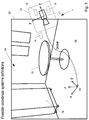
- FIG. 3 shows a system 1 in which a user (not shown) holds a mobile device 10 which incorporates or is coupled with a camera 11 for generating at least one image 30 of the real world, for example containing the real objects 31, 32 as shown.
- the real objects 31, 32 may be a table and a cabinet which are placed in a room having a ground plane 35, and the camera 11 takes an image of the real environment to be displayed on a display screen 20.
- the ground plane itself could also be considered to be a real object.
- the real environment is provided with a coordinate system 33, such as shown in Fig.
- the camera 11 is coupled with an image displaying means 20, such as a touchscreen that is incorporated in the mobile device 10.
- image displaying means such as a touchscreen
- any other image displaying means may be used which is suitable for displaying an image to a user, such as a head mounted display or any other type of mobile or stationary display device.
- a processing device 13 which may be for example a microprocessor, is connected with or incorporated in the mobile device 10.
- the mobile device 10 also incorporates or is coupled with an orientation sensor 12.
- the mobile device may be a mobile telephone having an integrated orientation sensor 12, camera 11, touchscreen 20, and processing device 13.
- the components may also be distributed and/or used in different applications. Further, they may be coupled with each other in wired or wireless fashion.
- the system 1 is used for determining the pose of a camera with respect to at least one object of a real environment for use in an authoring or augmented reality system.
- an image of the real environment may be augmented with a virtual object, such as shown in Fig. 5 , by displaying the virtual object 40 superimposed with the real environment in the image 30 in accordance with the pose of the camera.
- the pose (including position and orientation data) of the camera may be, for example, the pose with respect to the real object 31.
- the pose may be determined with respect to the coordinate system 33 as shown in Fig. 3 , which in turn is associated with the respective object 31.
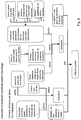
- the processing device 13 is arranged to perform the following steps in interaction with the camera 11 and the image displaying device 20:
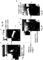
- FIGS. 2A-2D show a scene that is different from the previously described scene of Figures 3-5 .
- the images as shown in Figs. 2A, 2B correspond to a first image taken by a camera, such as the first image 30 as previously described.
- Figs. 2C, 2D display a respective second image 60 taken by the same or a different camera as described in more detail below.
- the same reference numerals for a first image (30) and a second image (60) are used in connection with the different scenes.
- a means for allocating a distance of the camera 11 to the real object 31 displayed in the image 30 generates distance data that is indicative of the allocated distance of the camera 11 to the real object 31.
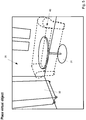
- providing the means for allocating the distance of the camera to the real object includes providing a virtual reference model that is displayed superimposed with the real environment in the first image 30.
- the initial distance of the reference object is a distance provided by a distance sensor.
- a reference model 50 is placed in the image 30 in accordance with an orientation provided by the orientation sensor 12.
- the dimensions of the reference model 50 (which may be any kind of virtual model), such as height, width or depth thereof, are known to the system.
- One implementation may include: Translate reference model parallel to oriented plane or apply a rotation to the reference model with an axis parallel to the plane's normal or move reference model along the line defined by the camera center and the center of mass of the object, already placed (which allows increasing or decreasing the size of the reference object in the image).
- the system is receiving user's instructions for manipulation of the reference model 50 by the user, the manipulation of the reference model including at least one of moving the reference model 50 at a particular position within the first image 30 on a plane, with the plane defined at least in part by the orientation data, and changing a dimension or variable of the reference model 50, such as moving the reference model 50 and/or changing the height of the reference model 50 (in Fig. 1 designated as moving and scaling the reference model).
- the distance data between camera 11 and real object 31 is determined using the virtual reference model 50, particularly using its known parameters such as height actually as actually displayed in the image 30.
- the system assumes that the user has correctly placed the reference model 50 within the image, so that the proportions of the reference model 50 correspond to the proportions of the real objects 31, 32 in the image 30.
- the distance between the camera 11 and the real object 31 can be derived taking into account the intrinsic camera parameters.
- the pose of the camera 11 with respect to the real object 31 (or with respect to the coordinate system 33 which is associated with the object 31) is then determined using the distance data from step 4.0 and the orientation data from step 2.0.
- the reference model 50 according to its final position and orientation defines the position and orientation of the coordinate system 33.
- step 5.0 at least one virtual object 40 as shown in Fig. 2B or Fig. 5 is superimposed with the real environment in the first image 30 in accordance with the determined pose of the camera.
- the reference model 50 may be blanked out, as shown in Fig. 2B .
- the manipulation of the reference model 50 by the user may include at least one of the following steps: touching the reference model by means of a touchscreen, using two fingers and moving the fingers away from each other to increase the size and moving the fingers closer to each other to decrease the size of the reference model (this might not be necessary, when having a distance measurement from a sensor), touching the reference model by means of a touchscreen with two fingers and rotating the fingers to one another in order to rotate the reference model around an axis perpendicular to the ground plane, touching the reference model with at least one finger and moving the finger in order to move the reference model across a plane.
- providing the means for allocating the distance of the camera 11 to the real object 31 includes providing a measurement device, such as a distance sensor, associated with the camera 11 for measuring at least one parameter indicative of the distance between the camera 11 and the real object 31, wherein the distance data are generated on the basis of the at least one parameter.
- the measurement device includes one of the following devices: a distance provided by a focussing unit of the camera, a distance sensor, at least one time of flight camera, and/or a stereo camera or cameras.
- a measurement device 14 is associated with the camera 11 for measuring a distance between the camera and the object 31.
- the processing device 13 coupled with the camera 11 is arranged for generating distance data from the measured distance, and for determining an initial pose of the camera with respect to the object 31 using the distance data and the orientation data.
- the initial pose can be refined in terms of the position on the ground plane and the rotation around the axis parallel to the plane's normal.
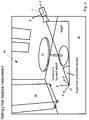
- Fig. 4 shows an example of how to determine the pose of the camera 11 knowing the distance to the focused object (which is in Fig. 4 different from table 31) and two angles describing the normal to the ground plane provided by the orientation sensor.
- One possibility to create the rotation matrix describing the plane's rotation to the camera is to set the first matrix column as the gravity vector (which might be provided by the orientation sensor).
- the second matrix vector is set as an arbitrary vector parallel to the plane perpendicular to the gravity vector.
- the third matrix column can be obtained using the cross product of the two other columns. All columns should be normalized.
- the method may further include providing a parameter indicative of a rotation of the camera around an axis which is perpendicular to the earth ground plane, e.g., provided by a rotation sensor or a compass (in Fig. 6 designated as z-rotation).
- a rotation sensor or a compass in Fig. 6 designated as z-rotation.
- providing the means for allocating the distance of the camera 11 to the real object 31 may include providing at least one parameter indicative of a distance between two features of the real environment which are visible in the image 30, such as a distance between the stand of the table 31 and one edge of the cabinet 32 and using the intrinsic camera parameters. Another helpful example is providing the distance of two features located on the ground plane.
- the parameter may be provided, interactively by the user, after an appropriate image processing algorithm, shows detected features and the user providing a distance from his knowledge of the real environment.
- the distance data and the orientation data are used to determine at least one placement coordinate system in the image 30, such as coordinate system 33, wherein the at least one virtual object 40 is superimposed with the real environment relative to the placement coordinate system 33.
- the system may not precisely determine the ground plane for allocating a corresponding coordinate system thereon, without, e.g. a distance sensor directed toward the ground.
- the placement coordinate system 33 is approximately the ground coordinate system.
- the ground plane and, thus, the ground coordinate system may be determined by means of a second image of the same scenery taken from a different pose of the camera, as explained in more detail below.
- Fig. 5 showing a virtual model 40 superimposed with the real environment, it should be noted that the virtual model 40 may also serve as the reference model 50 as discussed above with respect to Fig. 2A .
- the user may get an impression of how a real sofa corresponding to the virtual model 40 would look like if placed in the room of the real world. Therefore, the user may use his or her mobile phone for taking an image and for augmenting the image with virtual objects of any kind, wherein the skilled person is aware of a wide variety of applications.
- Another application for example could be placing objects in pictures of the real world and having a GPS position of the camera and an absolute orientation and determining the pose of a virtual model 40 using this invention, allowing to feed a global database of objects positioned on the earth, like GOOGLE® Earth.
- a distance of the reference model 50 is initially assumed. With moving the reference model 50 on a plane (with the plane being parallel to the ground plane) and/or with changing a dimension/parameter of the reference object according to the subjective impression of the user, the necessary translation data may be determined.
- a method will be explained in more detail for calculating a ground coordinate system on the basis of at least one second image or more images of the same scenery but taken from a different pose.
- the method includes the step of generating a second image 60 by a camera (which may be the same or a different camera for which the intrinsic parameters are also known than the camera which took the first image) capturing the real object (e.g. object 31 of image 30) of the real environment from a different pose.
- a camera which may be the same or a different camera for which the intrinsic parameters are also known than the camera which took the first image
- the real object e.g. object 31 of image 30
- step A2 at least one respective feature from the first image 30 and the second image 60 are extracted, wherein the respective features are matched to provide at least one relation indicative of a correspondence between the first image and the second image (the relation is designated in Fig. 8 in step A2 as "fundamental matrix" which is defined up to a scale (For more details see chapter 11 of Multiple View Geometry in Computer Vision. Second Edition. Richard Hartley and Andrew Zisserman, Cambridge University Press, March 2004 ). Te scale designated as "alpha" is determined in step B5).
- step A1 second orientation data derived from the new pose when taking the second image might be used to reduce the amount of needed features or to check the result of the fundamental matrix.
- the placement coordinate system 33 of the first image may be transitioned to the second image.
- the calculation of the fundamental matrix can of course be supported by the use of the orientation sensors, reducing the amount of necessary feature matches.
- step C1 the pose of the camera with respect to the real object in the first image is provided from the previous process with respect to the first image, and the pose of the camera with respect to the real object in the second image is determined using the pose of the camera with respect to the real object in the first image and the at least one relation, i.e. the fundamental matrix and "alpha" for determining the translation parameters tx, ty, tz of the pose which is consisting of the parameters tx, ty, tz, rx, ry, rz (with "t” standing for translation and "r” standing for rotation parameters in the three different dimensions) defining the position and orientation of the camera.
- the fundamental matrix and "alpha" for determining the translation parameters tx, ty, tz of the pose which is consisting of the parameters tx, ty, tz, rx, ry, rz (with "t” standing for translation and "r” standing for rotation parameters in the three different dimensions) defining the position and orientation of
- the distance data and the first orientation data recorded with respect to the first image were used to determine at least one placement coordinate system (such as coordinate system 33) in the first image and a position and orientation thereof in the first image (as discussed above), wherein the fundamental matrix and "alpha" are used for allocating the placement coordinate system in the second image with a position and orientation corresponding to the respective position and orientation in the first image.
- Fig. 2C in which the reference model 50 of Fig. 2A (positioned in accordance with the placement coordinate system 33) is shown in the second image 60 (positioned in accordance with the "transferred" placement coordinate system 33) with a position and orientation corresponding to the respective position and orientation in the first image 30 (i.e. with the back of the reference model turned to the wall as in the first image 30)
- the step of providing the at least one relation may further include one or more of the following steps:
- step B2 Providing at least one parameter indicative of a distance between two features of the real environment which are visible in both the first and second images (step B2).
- step B3 Providing at least one parameter indicative of a distance between two features of the real environment which are visible in both the first and second images (step B2).
- step B3 using 2D-3D-correspondences created from scale given by reference model 50 (and optionally assuming the reference model being on one plane) (step B3) may be applied for providing input to step B2.
- step B2 Providing at least one parameter indicative of a distance between two features of the real environment which are visible in one of the images (step B2) by assuming they are on the plane and assuming the reference model 50 is placed on the plane, the dimensions of the reference model providing a scale for the distance between the two features.
- a database of features including 3D positions or feature distances, near the position of one of the cameras could be queried for feature correspondences between features in one of the images and features in the database.
- This database could be created using sources of images, taken at known poses, like GOOGLE® Streetview. Matching features from overlapping images at two positions and using the mechanisms described above.
- Providing at least one parameter indicative of a distance between at least one feature, which is matched in both images, of the real environment and one camera (step B4). For example, a feature extracted close to the center of projection of the camera or close to where the distance measurement unit is aiming.
- step C1 after having placed the placement coordinate system in the second image with a position and orientation corresponding to the respective position and orientation in the first image, the pose to the placement coordinate system in both images is determined. Further, the 3D position of all matched feature correspondences in both images is determined. In step C2, either using the 3D positions of features or using the homography constraint, described above, the main plane can be determined, e.g. the ground plane.
- the placement coordinate system in the first image is positioned to be on the ground plane, e.g. by moving it along the plane's normal.
- FIGs 9-12 show a scenery which is different from the previously described scenes.
- the images as shown in Figs. 9-11 correspond to a first image taken by a camera, thus is designated with reference numeral 30 as with the previous described scenes.
- Fig. 12 displays a second image taken by the same or a different camera corresponding to the second image 60 as previously described.
- step C4 the method proceeds with superimposing at least one virtual object (such as object 71a in Fig. 9 , which may be a reference model or any virtual object to be superimposed with the real world) with the real environment in accordance with the placement coordinate system 33a as determined in the first image.
- the virtual object is superimposed with the real environment in accordance with the placement coordinate system 33a now positioned on the previously determined ground plane in the first image (now displayed as object 71b in Fig. 9 after moving the coordinate system 33a to the determined ground plane, the new positioned coordinate system designated as 33b).
- the process continues with moving the placement coordinate system 33b along the ground plane (in other words, adjust x,y).
- Fig. 9 the placement coordinate system 33b along the ground plane
- the placement coordinate system 33b is moved and positioned on the ground plane in that the projection of the virtual object in accordance with the (original) placement coordinate system 33a in the first image (object 71a) substantially equals or comes near (i.e. substantially corresponds to) the projection of the virtual object in accordance with the placement coordinate system 33b moved and positioned on the ground plane (object 71b).
- the process may continue with optionally scaling the virtual object 71b (i.e. change a dimension such as height thereof) so that it corresponds to the original dimension of the virtual object (object 71a) which was placed by the user originally in the first image 30.
- Another possibility to achieve this is to shoot a ray from the camera center on a point of the object (e.g. located in the lower part). The next step is intersecting the ray with the plane. Then, finally, we render the virtual object such that the point is superimposed with the intersection point.
- the process of correcting the position of objects might be done for all placed virtual objects individually not necessarily changing the placement coordinate system, but the relationship (tx,ty,tz, ry,ry,rz) of the virtual model to the placement coordinate system.
- the virtual object 71b is now superimposed with the real environment in accordance with the moved placement coordinate system on the ground plane in a second image 60, wherein Fig. 12 shows that the placement coordinate system as assumed in the first image 30 may be displaced from the actual ground plane.
- the superimposing of virtual objects 71a, 71b may be performed in the background, i.e. is not displayed on the display screen, but is only superimposed in the algorithm for determining the final placement coordinate system positioned correctly on the ground plane.
- This ground plane may be used in any further image for superimposing any virtual object with the real environment, irrespective of the respective perspective of the further image.
Landscapes
- Engineering & Computer Science (AREA)
- Physics & Mathematics (AREA)
- General Physics & Mathematics (AREA)
- Theoretical Computer Science (AREA)
- Computer Graphics (AREA)
- General Engineering & Computer Science (AREA)
- Computer Hardware Design (AREA)
- Software Systems (AREA)
- Signal Processing (AREA)
- Multimedia (AREA)
- Computer Vision & Pattern Recognition (AREA)
- Processing Or Creating Images (AREA)
- Studio Devices (AREA)
Claims (14)
- Verfahren zum Bestimmen der Position einer Kamera in Bezug auf mindestens ein Objekt einer realen Umgebung zur Verwendung in einer Augmented-Reality-Erstellungsanwendung, wobei das Verfahren folgende Schritte aufweist:Generieren eines ersten Bilds, das mindestens ein Bild von einer Kamera beinhaltet, die ein reales Objekt einer realen Umgebung aufnimmt;gekennzeichnet durch:Generieren von ersten Orientierungsdaten, die die Senkrechte auf die Grundebene bezeichnen, anhand von mindestens einem der Kamera zugeordneten Orientierungssensor;Bereitstellen eines virtuellen Referenzmodells, das der realen Umgebung in dem ersten Bild überlagert angezeigt wird;Empfangen von Nutzeranweisungen zum Manipulieren des virtuellen Referenzmodells durch einen Nutzer, so dass die Proportionen des virtuellen Referenzmodells den Proportionen des realen Objekts in dem ersten Bild entsprechen, wobei die Manipulation des virtuellen Referenzmodells mindestens eines beinhaltet von Bewegen des virtuellen Referenzmodells an eine bestimmte Position innerhalb des ersten Bilds auf einer Ebene, wobei die Ebene zumindest teilweise durch die ersten Orientierungsdaten definiert wird, und Ändern einer Dimension oder einer Variablen des virtuellen Referenzmodells;Zuweisen einer Distanz der Kamera zu dem realen Objekt der in dem ersten Bild angezeigten realen Umgebung und Generieren von Distanzdaten, die die Distanz angeben, wobei das Zuweisen der Distanz der Kamera zu dem realen Objekt das Bereitstellen einer der Kamera zugeordneten Messeinrichtung, die mindestens einen Parameter misst, der eine anfängliche Distanz zwischen der Kamera und dem realen Objekt angibt, und das Platzieren des virtuellen Referenzmodells in Abhängigkeit von der anfänglichen Distanz beinhaltet sowie das Generieren der Distanzdaten auf der Basis von dem mindestens einen Parameter sowie von einer Position des virtuellen Referenzmodells beinhaltet, die aus der Manipulation des virtuellen Referenzmodells und der Dimension des virtuellen Referenzmodells resultiert;undBestimmen einer Position der Kamera in Bezug auf ein Koordinatensystem, das zu dem realen Objekt der realen Umgebung in Beziehung steht, unter Verwendung der Distanzdaten und der ersten Orientierungsdaten.
- Verfahren nach Anspruch 1,
wobei die Manipulation des virtuellen Referenzmodells durch den Nutzer mindestens eines beinhalten kann von:Berühren des virtuellen Referenzmodells unter Verwendung eines Touch-screens, unter Verwendung von zwei Fingern und Bewegen der beiden Finger voneinander weg, um eine Größe des virtuellen Referenzmodells zu vergrößern, und Bewegen der beiden Finger näher zueinander hin, um die Größe des virtuellen Referenzmodells zu verkleinern;Berühren des virtuellen Referenzmodells unter Verwendung eines Touch-screens mit den beiden Fingern und Drehen der beiden Finger umeinander, um das virtuelle Referenzmodell um eine Achse senkrecht zu einer Grundebene zu drehen;Berühren des virtuellen Referenzmodells mit mindestens einem Finger und Bewegen des mindestens einen Fingers, um das virtuelle Referenzmodell über die Ebene zu bewegen. - Verfahren nach Anspruch 1 oder 2,
wobei die Manipulation des virtuellen Referenzmodells durch den Nutzer mindestens eines beinhalten kann von:Berühren des virtuellen Referenzmodells unter Verwendung eines Touch-screens, unter Verwendung von zwei Fingern und Bewegen der beiden Finger voneinander weg, um das virtuelle Referenzmodells näher zu einem Betrachter hin zu bewegen, wobei die Bewegung auf einer angenommenen Grundebene und parallel zu einem Schnittpunkt der angenommenen Grundebene mit einer Ebene stattfindet, die ein Kamerazentrum beinhaltet, wobei x in einem Kamerakoordinatensystem Null ist;Berühren des virtuellen Referenzmodells unter Verwendung eines Touch-screens, unter Verwendung der beiden Finger und Bewegen der beiden Finger näher zueinander hin, um das virtuelle Referenzmodell weiter von dem Betrachter weg zu bewegen, wobei die Bewegung auf der angenommenen Grundebene und parallel zu dem Schnittpunkt der angenommenen Grundebene mit der das Kamerazentrum beinhaltenden Ebene stattfindet, wobei x in dem Kamerakoordinatensystem Null ist;Berühren des virtuellen Referenzmodells unter Verwendung des Touchs-creens mit den beiden Fingern und Drehen der beiden Finger umeinander, um das virtuelle Referenzmodell um eine zu der angenommenen Grundebene senkrechte Achse zu drehen;Berühren des virtuellen Referenzmodells mit mindestens einem Finger und Bewegen des mindestens einen Fingers nach oben und nach unten, um das virtuelle Referenzmodell parallel zu einer Senkrechten auf die angenommene Grundebene zu bewegen;Berühren des virtuellen Referenzmodells mit dem mindestens einen Finger und Bewegen des mindestens einen Fingers nach links und nach rechts, um das virtuelle Referenzmodell auf der angenommenen Grundebene sowie parallel zu dem Schnittpunkt der angenommenen Grundebene mit der das Kamerazentrum enthaltenden Ebene zu bewegen, wobei y in dem Kamerakoordinatensystem Null ist. - Verfahren nach einem der Ansprüche 1 bis 3,
wobei das Bereitstellen der Messeinrichtung das Bereitstellen von mindestens einem von einer Fokussiereinheit der Kamera, einem unabhängigen Distanzsensor, mindestens einer TOF-Kamera, einer Stereokamera oder Stereokameras beinhaltet. - Verfahren nach einem der Ansprüche 1 bis 4,
das ferner das Bereitstellen eines Parameters beinhaltet, der eine Rotation der Kamera um eine Achse angibt, die senkrecht zu einer Grundebene der Erde ist. - Verfahren nach einem der Ansprüche 1 bis 5,
wobei das Zuweisen der Distanz der Kamera zu dem realen Objekt das Bereitstellen von mindestens einem Parameter beinhaltet, der eine Distanz zwischen zwei Merkmalen der realen Umgebung angibt, die in dem ersten Bild sichtbar sind. - Verfahren nach einem der Anspruch 1 bis 6,
das ferner das Anzeigen von mindestens einem virtuellen Objekt in Überlagerung mit der realen Umgebung in dem ersten Bild in Abhängigkeit von der Position der Kamera in Bezug auf das zu dem realen Objekt der realen Umgebung in Beziehung stehende Koordinatensystem beinhaltet, und Bestimmen von mindestens einem Platzierungskoordinatensystem in dem ersten Bild unter Verwendung der Distanzdaten und der ersten Orientierungsdaten, wobei das mindestens eine virtuelle Objekt der realen Umgebung relativ zu dem mindestens einen Platzierungskoordinatensystem überlagert wird. - Verfahren nach einem der Ansprüche 1 bis 7,
das ferner aufweist:Generieren eines zweiten Bilds mittels der Kamera, die das reale Objekt der realen Umgebung aufnimmt;Extrahieren von mindestens einem jeweiligen Merkmal aus dem ersten Bild und dem zweiten Bild und Einpassen des mindestens einen jeweiligen Merkmals in diese unter Schaffung mindestens einer Relation, die eine Entsprechung zwischen dem ersten Bild und dem zweiten Bild angibt; undBereitstellen der Position der Kamera in Bezug auf das zu dem realen Objekt in dem ersten Bild in Beziehung stehende Koordinatensystem und Bestimmen der Position der Kamera in Bezug auf ein zu dem realen Objekt in dem zweiten Bild in Beziehung stehendes Koordinatensystem unter Verwendung der Position der Kamera in Bezug auf das zu dem realen Objekt in dem ersten Bild in Beziehung stehende Koordinatensystem sowie der mindestens einen Relation,Generieren von dem zweiten Bild zugeordneten, zweiten Orientierungsdaten von dem mindestens einen Orientierungssensor,Bestimmen von mindestens einem Platzierungskoordinatensystem in dem ersten Bild sowie einer Position und Orientierung desselben in dem ersten Bild unter Verwendung der Distanzdaten und der ersten Orientierungsdaten;undZuweisen eines zweiten, mindestens einen Platzierungskoordinatensystems in dem zweiten Bild zu einer zweiten Position und Orientierung, die der jeweiligen Position und Orientierung in dem ersten Bild entsprechen, unter Verwendung der mindestens einen Relation, wobei das Schaffen der mindestens einen Relation ferner mindestens eines von Folgendem aufweist:Bereitstellen von mindestens einem Parameter, der eine Bewegung der Kamera zwischen der Aufnahme des ersten Bilds und des zweiten Bilds angibt;Bereitstellen eines zweiten, mindestens einen Parameters, der eine Distanz zwischen zwei Merkmalen der realen Umgebung angibt, die sowohl in dem ersten Bild als auch in dem zweiten Bild sichtbar sind;Bereitstellen eines dritten, mindestens einen Parameters, der eine Distanz zwischen mindestens einem Merkmal der realen Umgebung und der Kamera angibt. - Verfahren nach Anspruch 8,
wobei das Bereitstellen des mindestens einen Parameters, der die Bewegung der Kamera zwischen der Aufnahme des ersten Bilds und des zweiten Bilds angibt, das Bereitstellen eines ersten Standortparameters der Kamera beim Aufnehmen des ersten Bilds und eines zweiten Standortparameters der Kamera beim Aufnehmen des zweiten Bilds sowie das Generieren von mindestens einem von dem ersten und dem zweiten Standortparameter mittels mindestens einem von einem Satellitenortungssystem und einer Höhenmesseinrichtung beinhaltet. - Verfahren nach einem der Ansprüche 1 bis 9,
das weiterhin beinhaltet:Bereitstellen eines virtuellen Referenzmodells, das der realen Umgebung in dem ersten Bild überlagert angezeigt wird, Platzieren des angenommenen virtuellen Referenzmodells auf einer angenommenen Grundebene und in dem ersten Bild erfolgendes Identifizieren von mindestens zwei Merkmalen der realen Umgebung auf der angenommenen Grundebene in der Nähe des virtuellen Referenzmodells, wobei eine Distanz zwischen den mindestens zwei Merkmalen unter Verwendung einer bekannten Dimension des virtuellen Referenzmodells bestimmt wird. - Verfahren nach einem der Ansprüche 1 bis 10,
das weiterhin beinhaltet:Extrahieren von mindestens einem zweiten jeweiligen Merkmal aus dem ersten Bild und einem zweiten Bild zum Bestimmen einer Grundebene sowohl in dem ersten Bild aus auch in dem zweiten Bild, und Bewegen eines Platzierungskoordinatensystems zur Positionierung desselben auf der Grundebene. - Verfahren nach Anspruch 11,
das weiterhin beinhaltet:Überlagern der realen Umgebung mit mindestens einem virtuellen Objekt in Übereinstimmung mit dem Platzierungskoordinatensystem in dem ersten Bild;Überlagern der realen Umgebung mit dem mindestens einen virtuellen Objekt in Übereinstimmung mit dem auf der Grundebene positionierten Platzierungskoordinatensystem in dem ersten Bild;Bewegen des Platzierungskoordinatensystems entlang der zu positionierenden Grundebene derart, dass eine Projektion des mindestens einen virtuellen Objekts in Übereinstimmung mit dem Platzierungskoordinatensystem in dem ersten Bild der Projektion des mindestens einen virtuellen Objekts in Übereinstimmung mit dem auf der Grundebene positionierten Platzierungskoordinatensystem im Wesentlichen entspricht oder dieser nahe kommt. - System zum Bestimmen der Position einer Kamera in Bezug auf mindestens ein Objekt einer realen Umgebung zur Verwendung in einer Augmented-Reality-Erstellungsanwendung, aufweisend:mindestens eine Kamera, die zum Generieren von mindestens einem Bild ausgebildet ist, das mindestens ein Objekt einer realen Umgebung auf-nimmt;eine Bildanzeigeeinrichtung, die zum Anzeigen des mindestens einen Bilds ausgebildet ist;gekennzeichnet durch:mindestens einen Orientierungssensor, der der mindestens einen Kamera zugeordnet ist und dazu ausgebildet ist, Orientierungsdaten der mindestens einen Kamera zu generieren, die die Senkrechte auf die Grundebene bezeichnen;eine der Kamera zugeordnete Messeinrichtung, die zum Messen von mindestens einem Parameter ausgebildet ist, der eine anfängliche Distanz zwischen der Kamera und dem mindestens eine Objekt angibt,eine Verarbeitungseinrichtung, die mit der mindestens einen Kamera undmit der Bildanzeigeeinrichtung gekoppelt ist, wobei die Verarbeitungseinrichtung dazu ausgebildet ist:ein virtuelles Referenzmodell bereitzustellen, das der realen Umgebung in dem mindestens einen Bild überlagert angezeigt wird und in Abhängigkeit von der anfänglichen Distanz platziert wird;Nutzeranweisungen zu empfangen über eine Nutzerschnittstelle zur Manipulation des virtuellen Referenzmodells durch einen Nutzer, so dass die Proportionen des virtuellen Referenzmodells den Proportionen des mindestens einen Objekts in dem mindestens einen Bild entsprechen, wobei die Manipulation des virtuellen Referenzmodells mindestens eines beinhaltet von Bewegen des virtuellen Referenzmodells an eine bestimmte Position innerhalb des mindestens einen Bilds auf einer Ebene, wobei die Ebene zumindest teilweise durch die Orientierungsdaten definiert wird, und Ändern einer Dimension oder Variablen des virtuellen Referenzmodells;Distanzdaten zu erzeugen auf der Basis des mindestens einen Parameters und aus einer Position des virtuellen Referenzmodells, die aus der Manipulation des virtuellen Referenzmodells und der Dimension des virtuellen Referenzmodells resultiert, wobei die Distanzdaten eine zugewiesene Distanz der mindestens einen Kamera zu dem mindestens einen Objekt angeben;sowie die Position der mindestens einen Kamera in Bezug auf ein Koordinatensystem, das zu dem mindestens einen Objekt der realen Umgebung in Beziehung steht, unter Nutzung der Distanzdaten und der Orientierungsdaten zu bestimmen.
- System nach Anspruch 13,
wobei das System in einem Mobilgerät enthalten ist, bei dem es sich insbesondere um ein Mobiltelefon handelt.
Applications Claiming Priority (2)
| Application Number | Priority Date | Filing Date | Title |
|---|---|---|---|
| US12/371,490 US8970690B2 (en) | 2009-02-13 | 2009-02-13 | Methods and systems for determining the pose of a camera with respect to at least one object of a real environment |
| PCT/EP2010/000882 WO2010091875A2 (en) | 2009-02-13 | 2010-02-12 | Methods and systems for determining the pose of a camera with respect to at least one object of a real environment |
Publications (2)
| Publication Number | Publication Date |
|---|---|
| EP2396767A2 EP2396767A2 (de) | 2011-12-21 |
| EP2396767B1 true EP2396767B1 (de) | 2017-03-22 |
Family
ID=42235284
Family Applications (1)
| Application Number | Title | Priority Date | Filing Date |
|---|---|---|---|
| EP10713797.8A Active EP2396767B1 (de) | 2009-02-13 | 2010-02-12 | Verfahren und systeme zur bestimmung der position einer kamera hinsichtlich mindestens eines objekts einer echten umgebung |
Country Status (4)
| Country | Link |
|---|---|
| US (2) | US8970690B2 (de) |
| EP (1) | EP2396767B1 (de) |
| CN (2) | CN102395997B (de) |
| WO (1) | WO2010091875A2 (de) |
Families Citing this family (156)
| Publication number | Priority date | Publication date | Assignee | Title |
|---|---|---|---|---|
| US7961909B2 (en) | 2006-03-08 | 2011-06-14 | Electronic Scripting Products, Inc. | Computer interface employing a manipulated object with absolute pose detection component and a display |
| US20160098095A1 (en) * | 2004-01-30 | 2016-04-07 | Electronic Scripting Products, Inc. | Deriving Input from Six Degrees of Freedom Interfaces |
| US8730156B2 (en) * | 2010-03-05 | 2014-05-20 | Sony Computer Entertainment America Llc | Maintaining multiple views on a shared stable virtual space |
| US9013505B1 (en) * | 2007-11-27 | 2015-04-21 | Sprint Communications Company L.P. | Mobile system representing virtual objects on live camera image |
| US8970690B2 (en) | 2009-02-13 | 2015-03-03 | Metaio Gmbh | Methods and systems for determining the pose of a camera with respect to at least one object of a real environment |
| US8698875B2 (en) | 2009-02-20 | 2014-04-15 | Google Inc. | Estimation of panoramic camera orientation relative to a vehicle coordinate frame |
| US20100306825A1 (en) | 2009-05-27 | 2010-12-02 | Lucid Ventures, Inc. | System and method for facilitating user interaction with a simulated object associated with a physical location |
| EP2359915B1 (de) * | 2009-12-31 | 2017-04-19 | Sony Computer Entertainment Europe Limited | Medienbetrachtung |
| JP5728159B2 (ja) * | 2010-02-02 | 2015-06-03 | ソニー株式会社 | 画像処理装置、画像処理方法及びプログラム |
| US8797353B2 (en) * | 2010-02-12 | 2014-08-05 | Samsung Electronics Co., Ltd. | Augmented media message |
| CN102906810B (zh) | 2010-02-24 | 2015-03-18 | 爱普莱克斯控股公司 | 支持视觉受损的个体的扩增的现实全景 |
| KR20130049769A (ko) * | 2010-03-17 | 2013-05-14 | 소니 주식회사 | 정보 처리 장치, 정보 처리 방법 및 프로그램 |
| JP5578691B2 (ja) * | 2010-06-01 | 2014-08-27 | サーブ アクティエボラーグ | 拡張現実のための方法および装置 |
| JP5624394B2 (ja) * | 2010-07-16 | 2014-11-12 | キヤノン株式会社 | 位置姿勢計測装置、その計測処理方法及びプログラム |
| US9013550B2 (en) * | 2010-09-09 | 2015-04-21 | Qualcomm Incorporated | Online reference generation and tracking for multi-user augmented reality |
| JP5799521B2 (ja) | 2011-02-15 | 2015-10-28 | ソニー株式会社 | 情報処理装置、オーサリング方法及びプログラム |
| US9398210B2 (en) | 2011-02-24 | 2016-07-19 | Digimarc Corporation | Methods and systems for dealing with perspective distortion in connection with smartphone cameras |
| US10972680B2 (en) * | 2011-03-10 | 2021-04-06 | Microsoft Technology Licensing, Llc | Theme-based augmentation of photorepresentative view |
| JP5702653B2 (ja) * | 2011-04-08 | 2015-04-15 | 任天堂株式会社 | 情報処理プログラム、情報処理装置、情報処理システム、および、情報処理方法 |
| US8638986B2 (en) * | 2011-04-20 | 2014-01-28 | Qualcomm Incorporated | Online reference patch generation and pose estimation for augmented reality |
| US9582707B2 (en) | 2011-05-17 | 2017-02-28 | Qualcomm Incorporated | Head pose estimation using RGBD camera |
| US20120331422A1 (en) * | 2011-06-22 | 2012-12-27 | Gemvision Corporation, LLC | Custom Jewelry Configurator |
| EP2751742A1 (de) * | 2011-08-31 | 2014-07-09 | metaio GmbH | Verfahren zum abgleich von bildmerkmalen mit referenzmerkmalen |
| JP5838747B2 (ja) * | 2011-11-11 | 2016-01-06 | ソニー株式会社 | 情報処理装置、情報処理方法、及びプログラム |
| US9395188B2 (en) * | 2011-12-01 | 2016-07-19 | Maxlinear, Inc. | Method and system for location determination and navigation using structural visual information |
| US9443353B2 (en) | 2011-12-01 | 2016-09-13 | Qualcomm Incorporated | Methods and systems for capturing and moving 3D models and true-scale metadata of real world objects |
| EP2613295B1 (de) * | 2012-01-03 | 2017-03-08 | Harman Becker Automotive Systems GmbH | Geografische Kartenquerformat-Texturerzeugung auf Basis von Bildern einer tragbaren Kamera |
| EP2800996A4 (de) | 2012-01-06 | 2015-08-19 | Blackberry Ltd | System und verfahren zur ausrichtung einer kamera |
| EP2615580B1 (de) * | 2012-01-13 | 2016-08-17 | Softkinetic Software | Automatische Szenenkalibrierung |
| US9529426B2 (en) | 2012-02-08 | 2016-12-27 | Microsoft Technology Licensing, Llc | Head pose tracking using a depth camera |
| WO2013126784A2 (en) | 2012-02-23 | 2013-08-29 | Huston Charles D | System and method for creating an environment and for sharing a location based experience in an environment |
| US10937239B2 (en) | 2012-02-23 | 2021-03-02 | Charles D. Huston | System and method for creating an environment and for sharing an event |
| US10600235B2 (en) | 2012-02-23 | 2020-03-24 | Charles D. Huston | System and method for capturing and sharing a location based experience |
| US20130278633A1 (en) * | 2012-04-20 | 2013-10-24 | Samsung Electronics Co., Ltd. | Method and system for generating augmented reality scene |
| US20130303247A1 (en) * | 2012-05-08 | 2013-11-14 | Mediatek Inc. | Interaction display system and method thereof |
| GB2501929B (en) * | 2012-05-11 | 2015-06-24 | Sony Comp Entertainment Europe | Apparatus and method for augmented reality |
| US9147122B2 (en) | 2012-05-31 | 2015-09-29 | Qualcomm Incorporated | Pose estimation based on peripheral information |
| US9224205B2 (en) | 2012-06-14 | 2015-12-29 | Qualcomm Incorporated | Accelerated geometric shape detection and accurate pose tracking |
| GB2519266B (en) * | 2012-08-15 | 2015-08-26 | Ibm | Feature extraction method, program and system |
| EP2699006A1 (de) * | 2012-08-16 | 2014-02-19 | ESSILOR INTERNATIONAL (Compagnie Générale d'Optique) | Bildpositionierung auf Anzeigeelementen |
| CN103673990B (zh) * | 2012-09-13 | 2016-04-06 | 北京同步科技有限公司 | 获取摄像机姿态数据的装置及其方法 |
| US20140123507A1 (en) * | 2012-11-02 | 2014-05-08 | Qualcomm Incorporated | Reference coordinate system determination |
| US9576183B2 (en) | 2012-11-02 | 2017-02-21 | Qualcomm Incorporated | Fast initialization for monocular visual SLAM |
| US9953618B2 (en) * | 2012-11-02 | 2018-04-24 | Qualcomm Incorporated | Using a plurality of sensors for mapping and localization |
| US9159133B2 (en) | 2012-11-05 | 2015-10-13 | Qualcomm Incorporated | Adaptive scale and/or gravity estimation |
| US9213419B1 (en) * | 2012-11-13 | 2015-12-15 | Amazon Technologies, Inc. | Orientation inclusive interface navigation |
| EP2736247A1 (de) * | 2012-11-26 | 2014-05-28 | Brainstorm Multimedia, S.L. | Verfahren zum Erhalt eines virtuellen Objektes innerhalb eines virtuellen Studios von einem realen Objekt |
| US9113077B2 (en) * | 2013-01-17 | 2015-08-18 | Qualcomm Incorporated | Orientation determination based on vanishing point computation |
| US10733798B2 (en) * | 2013-03-14 | 2020-08-04 | Qualcomm Incorporated | In situ creation of planar natural feature targets |
| JP6112925B2 (ja) * | 2013-03-15 | 2017-04-12 | オリンパス株式会社 | 表示機器及び表示方法 |
| JP6255706B2 (ja) * | 2013-04-22 | 2018-01-10 | 富士通株式会社 | 表示制御装置、表示制御方法、表示制御プログラムおよび情報提供システム |
| JP5887310B2 (ja) * | 2013-07-29 | 2016-03-16 | 京セラドキュメントソリューションズ株式会社 | 表示操作装置 |
| US9595125B2 (en) * | 2013-08-30 | 2017-03-14 | Qualcomm Incorporated | Expanding a digital representation of a physical plane |
| JP6476658B2 (ja) * | 2013-09-11 | 2019-03-06 | ソニー株式会社 | 画像処理装置および方法 |
| US9400930B2 (en) * | 2013-09-27 | 2016-07-26 | Qualcomm Incorporated | Hybrid photo navigation and mapping |
| US9286718B2 (en) * | 2013-09-27 | 2016-03-15 | Ortery Technologies, Inc. | Method using 3D geometry data for virtual reality image presentation and control in 3D space |
| WO2015080750A1 (en) | 2013-11-29 | 2015-06-04 | Hewlett-Packard Development Company, L.P. | Hologram for alignment |
| CN104717413A (zh) * | 2013-12-12 | 2015-06-17 | 北京三星通信技术研究有限公司 | 拍照辅助方法及设备 |
| WO2015087425A1 (ja) * | 2013-12-12 | 2015-06-18 | 富士通株式会社 | 設備点検作業支援プログラム、設備点検作業支援方法及び設備点検作業支援装置 |
| KR102059311B1 (ko) * | 2013-12-19 | 2019-12-24 | 애플 인크. | 모바일 디바이스에서의 slam |
| US20160343166A1 (en) * | 2013-12-24 | 2016-11-24 | Teamlab Inc. | Image-capturing system for combining subject and three-dimensional virtual space in real time |
| US9560254B2 (en) * | 2013-12-30 | 2017-01-31 | Google Technology Holdings LLC | Method and apparatus for activating a hardware feature of an electronic device |
| US9595109B1 (en) * | 2014-01-30 | 2017-03-14 | Inertial Labs, Inc. | Digital camera with orientation sensor for optical tracking of objects |
| US10932103B1 (en) * | 2014-03-21 | 2021-02-23 | Amazon Technologies, Inc. | Determining position of a user relative to a tote |
| US9911190B1 (en) | 2014-04-09 | 2018-03-06 | Vortex Intellectual Property Holding LLC | Method and computer program for generating a database for use in locating mobile devices based on imaging |
| US10157189B1 (en) | 2014-04-09 | 2018-12-18 | Vortex Intellectual Property Holding LLC | Method and computer program for providing location data to mobile devices |
| US9418284B1 (en) * | 2014-04-09 | 2016-08-16 | Vortex Intellectual Property Holding LLC | Method, system and computer program for locating mobile devices based on imaging |
| US10735902B1 (en) | 2014-04-09 | 2020-08-04 | Accuware, Inc. | Method and computer program for taking action based on determined movement path of mobile devices |
| US20220383600A1 (en) * | 2014-05-13 | 2022-12-01 | West Texas Technology Partners, Llc | Method for interactive catalog for 3d objects within the 2d environment |
| US11410394B2 (en) | 2020-11-04 | 2022-08-09 | West Texas Technology Partners, Inc. | Method for interactive catalog for 3D objects within the 2D environment |
| US9977844B2 (en) | 2014-05-13 | 2018-05-22 | Atheer, Inc. | Method for providing a projection to align 3D objects in 2D environment |
| IL232853A (en) * | 2014-05-28 | 2015-11-30 | Elbit Systems Land & C4I Ltd | Method and system for image georegistration |
| US10026226B1 (en) | 2014-06-10 | 2018-07-17 | Ripple Inc | Rendering an augmented reality object |
| US10930038B2 (en) | 2014-06-10 | 2021-02-23 | Lab Of Misfits Ar, Inc. | Dynamic location based digital element |
| US12008697B2 (en) | 2014-06-10 | 2024-06-11 | Ripple, Inc. Of Delaware | Dynamic location based digital element |
| WO2016012041A1 (en) * | 2014-07-23 | 2016-01-28 | Metaio Gmbh | Method and system for presenting at least part of an image of a real object in a view of a real environment, and method and system for selecting a subset of a plurality of images |
| US9858720B2 (en) | 2014-07-25 | 2018-01-02 | Microsoft Technology Licensing, Llc | Three-dimensional mixed-reality viewport |
| US9766460B2 (en) | 2014-07-25 | 2017-09-19 | Microsoft Technology Licensing, Llc | Ground plane adjustment in a virtual reality environment |
| US9865089B2 (en) | 2014-07-25 | 2018-01-09 | Microsoft Technology Licensing, Llc | Virtual reality environment with real world objects |
| US9904055B2 (en) | 2014-07-25 | 2018-02-27 | Microsoft Technology Licensing, Llc | Smart placement of virtual objects to stay in the field of view of a head mounted display |
| US10451875B2 (en) | 2014-07-25 | 2019-10-22 | Microsoft Technology Licensing, Llc | Smart transparency for virtual objects |
| US10311638B2 (en) | 2014-07-25 | 2019-06-04 | Microsoft Technology Licensing, Llc | Anti-trip when immersed in a virtual reality environment |
| US10416760B2 (en) | 2014-07-25 | 2019-09-17 | Microsoft Technology Licensing, Llc | Gaze-based object placement within a virtual reality environment |
| TWI628613B (zh) * | 2014-12-09 | 2018-07-01 | 財團法人工業技術研究院 | 擴增實境方法與系統 |
| TWI524758B (zh) | 2014-12-09 | 2016-03-01 | 財團法人工業技術研究院 | 電子裝置及其漸增式姿態估算及攝影方法 |
| CN104462730B (zh) * | 2014-12-31 | 2018-01-30 | 广东电网有限责任公司电力科学研究院 | 电厂在线仿真系统和方法 |
| US9412034B1 (en) * | 2015-01-29 | 2016-08-09 | Qualcomm Incorporated | Occlusion handling for computer vision |
| JP6336922B2 (ja) * | 2015-01-30 | 2018-06-06 | 株式会社日立製作所 | 業務バリエーションに基づく業務影響箇所抽出方法および業務影響箇所抽出装置 |
| US10001376B1 (en) * | 2015-02-19 | 2018-06-19 | Rockwell Collins, Inc. | Aircraft position monitoring system and method |
| CN108139876B (zh) * | 2015-03-04 | 2022-02-25 | 杭州凌感科技有限公司 | 用于沉浸式和交互式多媒体生成的系统和方法 |
| US10073848B2 (en) * | 2015-03-17 | 2018-09-11 | Siemens Aktiengesellschaft | Part identification using a photograph and engineering data |
| US9683849B2 (en) * | 2015-04-01 | 2017-06-20 | Trimble Inc. | Vehicle navigation system with adaptive gyroscope bias compensation |
| ES2834553T3 (es) * | 2015-06-12 | 2021-06-17 | Accenture Global Services Ltd | Un método y sistema de realidad aumentada de medición y/o fabricación |
| US9865091B2 (en) * | 2015-09-02 | 2018-01-09 | Microsoft Technology Licensing, Llc | Localizing devices in augmented reality environment |
| US10089681B2 (en) | 2015-12-04 | 2018-10-02 | Nimbus Visulization, Inc. | Augmented reality commercial platform and method |
| US9767606B2 (en) * | 2016-01-12 | 2017-09-19 | Lenovo (Singapore) Pte. Ltd. | Automatic modification of augmented reality objects |
| KR102721084B1 (ko) * | 2016-02-05 | 2024-10-22 | 매직 립, 인코포레이티드 | 증강 현실을 위한 시스템들 및 방법들 |
| US9881378B2 (en) | 2016-02-12 | 2018-01-30 | Vortex Intellectual Property Holding LLC | Position determining techniques using image analysis of marks with encoded or associated position data |
| JP6665572B2 (ja) * | 2016-02-16 | 2020-03-13 | 富士通株式会社 | 制御プログラム、制御方法およびコンピュータ |
| US10824878B2 (en) | 2016-03-08 | 2020-11-03 | Accuware, Inc. | Method and arrangement for receiving data about site traffic derived from imaging processing |
| DE102016204140B3 (de) * | 2016-03-14 | 2017-04-06 | pmdtechnologies ag | Vorrichtung und Verfahren zur Kalibrierung einer Lichtlaufzeitkamera |
| US11577159B2 (en) | 2016-05-26 | 2023-02-14 | Electronic Scripting Products Inc. | Realistic virtual/augmented/mixed reality viewing and interactions |
| CN105937878B (zh) * | 2016-06-13 | 2018-10-26 | 歌尔科技有限公司 | 一种室内测距方法 |
| WO2018013495A1 (en) * | 2016-07-11 | 2018-01-18 | Gravity Jack, Inc. | Augmented reality methods and devices |
| EP3494447B1 (de) | 2016-08-04 | 2021-05-19 | Reification Inc. | Verfahren für simultane lokalisierung und mapping (slam) und zugehörige vorrichtungen und systeme |
| EP3500822A4 (de) | 2016-08-18 | 2019-08-28 | SZ DJI Technology Co., Ltd. | Systeme und verfahren zur erweiterten stereoskopischen darstellung |
| CN106780757B (zh) * | 2016-12-02 | 2020-05-12 | 西北大学 | 一种增强现实的方法 |
| CN106774870A (zh) * | 2016-12-09 | 2017-05-31 | 武汉秀宝软件有限公司 | 一种增强现实交互方法及系统 |
| US10139934B2 (en) | 2016-12-22 | 2018-11-27 | Microsoft Technology Licensing, Llc | Magnetic tracker dual mode |
| US10843068B2 (en) | 2017-01-18 | 2020-11-24 | Xvisio Technology Corp. | 6DoF inside-out tracking game controller |
| US10146300B2 (en) | 2017-01-25 | 2018-12-04 | Lenovo Enterprise Solutions (Singapore) Pte. Ltd. | Emitting a visual indicator from the position of an object in a simulated reality emulation |
| CN116863107A (zh) * | 2017-03-06 | 2023-10-10 | 连株式会社 | 增强现实提供方法、装置以及非暂时性计算机可读介质 |
| CN107168514B (zh) * | 2017-03-27 | 2020-02-21 | 联想(北京)有限公司 | 一种图像处理方法及电子设备 |
| US10692287B2 (en) | 2017-04-17 | 2020-06-23 | Microsoft Technology Licensing, Llc | Multi-step placement of virtual objects |
| US10740613B1 (en) | 2017-04-20 | 2020-08-11 | Digimarc Corporation | Hybrid feature point/watermark-based augmented reality |
| US10339714B2 (en) * | 2017-05-09 | 2019-07-02 | A9.Com, Inc. | Markerless image analysis for augmented reality |
| US10282860B2 (en) * | 2017-05-22 | 2019-05-07 | Honda Motor Co., Ltd. | Monocular localization in urban environments using road markings |
| EP3416027B1 (de) | 2017-06-12 | 2020-04-08 | Hexagon Technology Center GmbH | Augmentierte realität vorrichtung und system mit nahtloser überbrückung |
| US10242292B2 (en) * | 2017-06-13 | 2019-03-26 | Digital Surgery Limited | Surgical simulation for training detection and classification neural networks |
| US10462370B2 (en) | 2017-10-03 | 2019-10-29 | Google Llc | Video stabilization |
| DE102017220458A1 (de) * | 2017-11-16 | 2019-05-16 | Robert Bosch Gmbh | Kalibriereinrichtung und Verfahren zum Kalibrieren eines Referenztargets |
| CN109840947B (zh) * | 2017-11-28 | 2023-05-09 | 广州腾讯科技有限公司 | 增强现实场景的实现方法、装置、设备及存储介质 |
| US10652472B2 (en) * | 2018-02-22 | 2020-05-12 | Adobe Inc. | Enhanced automatic perspective and horizon correction |
| CN110349472B (zh) * | 2018-04-02 | 2021-08-06 | 北京五一视界数字孪生科技股份有限公司 | 一种虚拟驾驶应用中虚拟方向盘和真实方向盘对接方法 |
| US10171738B1 (en) * | 2018-05-04 | 2019-01-01 | Google Llc | Stabilizing video to reduce camera and face movement |
| CN110827376A (zh) * | 2018-08-09 | 2020-02-21 | 北京微播视界科技有限公司 | 增强现实多平面模型动画交互方法、装置、设备及存储介质 |
| CN110825279A (zh) * | 2018-08-09 | 2020-02-21 | 北京微播视界科技有限公司 | 平面间无缝切换的方法、装置和计算机可读存储介质 |
| CN110827411B (zh) * | 2018-08-09 | 2023-07-18 | 北京微播视界科技有限公司 | 自适应环境的增强现实模型显示方法、装置、设备及存储介质 |
| US10573019B1 (en) * | 2018-09-25 | 2020-02-25 | Ebay Inc. | Augmented reality digital content search and sizing techniques |
| EP3861387B1 (de) | 2018-10-05 | 2025-05-21 | Magic Leap, Inc. | Darstellung eines ortsspezifischen virtuellen inhalts an einem beliebigen ort |
| EP3640767B1 (de) * | 2018-10-17 | 2024-09-11 | Siemens Schweiz AG | Verfahren zum bestimmen mindestens eines bereichs in mindestens einem eingabemodell für mindestens ein zu platzierendes element |
| US10735665B2 (en) * | 2018-10-30 | 2020-08-04 | Dell Products, Lp | Method and system for head mounted display infrared emitter brightness optimization based on image saturation |
| US12073515B2 (en) * | 2019-03-28 | 2024-08-27 | Nec Corporation | Information processing apparatus, display system, display method, and non-transitory computer readable medium storing program |
| CN111247389B (zh) * | 2019-03-29 | 2022-03-25 | 深圳市大疆创新科技有限公司 | 关于拍摄设备的数据处理方法、装置及图像处理设备 |
| CN110069135A (zh) * | 2019-04-28 | 2019-07-30 | 联想(北京)有限公司 | 一种人机交互设备的数据处理方法及人机交互设备 |
| US10955245B2 (en) | 2019-04-30 | 2021-03-23 | Samsung Electronics Co., Ltd. | System and method for low latency, high performance pose fusion |
| US11257294B2 (en) | 2019-10-15 | 2022-02-22 | Magic Leap, Inc. | Cross reality system supporting multiple device types |
| US11138760B2 (en) * | 2019-11-06 | 2021-10-05 | Varjo Technologies Oy | Display systems and methods for correcting drifts in camera poses |
| JP2021077185A (ja) * | 2019-11-12 | 2021-05-20 | ソニー株式会社 | 情報処理装置、情報処理方法、並びにプログラム |
| TWI900505B (zh) | 2019-11-26 | 2025-10-11 | 瑞士商赫孚孟拉羅股份公司 | 執行分析測量的方法及相關電腦程式、電腦可讀取儲存媒體、行動裝置及套組 |
| JP7748945B2 (ja) | 2019-12-09 | 2025-10-03 | マジック リープ, インコーポレイテッド | 仮想コンテンツの簡略化されたプログラミングを伴うクロスリアリティシステム |
| US11288877B2 (en) | 2020-01-10 | 2022-03-29 | 38th Research Institute, China Electronics Technology Group Corp. | Method for matching a virtual scene of a remote scene with a real scene for augmented reality and mixed reality |
| CN111260793B (zh) * | 2020-01-10 | 2020-11-24 | 中国电子科技集团公司第三十八研究所 | 面向增强和混合现实的远程虚实高精度匹配定位的方法 |
| DE102020101398A1 (de) * | 2020-01-22 | 2021-07-22 | Audi Aktiengesellschaft | Verfahren zum Erzeugen von reproduzierbaren Perspektiven von Fotografien eines Objekts sowie mobiles Gerät mit integrierter Kamera |
| JP7768888B2 (ja) | 2020-02-13 | 2025-11-12 | マジック リープ, インコーポレイテッド | マルチ分解能フレーム記述子を使用したマップ処理を伴うクロスリアリティシステム |
| US11551430B2 (en) | 2020-02-26 | 2023-01-10 | Magic Leap, Inc. | Cross reality system with fast localization |
| WO2021173862A1 (en) | 2020-02-26 | 2021-09-02 | Magic Leap, Inc. | Cross reality system with buffering for localization accuracy |
| US11190689B1 (en) | 2020-07-29 | 2021-11-30 | Google Llc | Multi-camera video stabilization |
| US11640713B2 (en) | 2020-07-29 | 2023-05-02 | Optima Sports Systems S.L. | Computing system and a computer-implemented method for sensing gameplay events and augmentation of video feed with overlay |
| EP4475012A3 (de) | 2020-07-29 | 2025-01-22 | Optima Sports Systems S.L. | Rechnersystem und computer-implementiertes verfahren zur erfassung von ereignissen aus georäumlichen daten |
| US11348277B2 (en) * | 2020-08-12 | 2022-05-31 | Hong Kong Applied Science and Technology Research Institute Company Limited | Apparatus and method for estimating camera orientation relative to ground surface |
| US12002235B2 (en) * | 2020-08-12 | 2024-06-04 | Hong Kong Applied Science and Technology Research Institute Company Limited | Apparatus and method for estimating camera orientation relative to ground surface |
| CN112102406B (zh) * | 2020-09-09 | 2024-07-26 | 东软睿驰汽车技术(沈阳)有限公司 | 单目视觉的尺度修正方法、装置及运载工具 |
| EP4352451A4 (de) * | 2021-05-20 | 2025-09-17 | Eigen Innovations Inc | Texturabbildung auf polygonalen modellen für industrielle inspektionen |
| CA3267422A1 (en) * | 2022-09-23 | 2024-03-28 | Eigen Innovations Inc. | INSPECTION CAMERA DEPLOYMENT SOLUTION |
| US12608841B2 (en) * | 2023-01-24 | 2026-04-21 | Varjo Technologies Oy | Plane estimation using object detection |
Family Cites Families (32)
| Publication number | Priority date | Publication date | Assignee | Title |
|---|---|---|---|---|
| JP3363861B2 (ja) * | 2000-01-13 | 2003-01-08 | キヤノン株式会社 | 複合現実感提示装置及び複合現実感提示方法並びに記憶媒体 |
| US6891518B2 (en) * | 2000-10-05 | 2005-05-10 | Siemens Corporate Research, Inc. | Augmented reality visualization device |
| US6765569B2 (en) | 2001-03-07 | 2004-07-20 | University Of Southern California | Augmented-reality tool employing scene-feature autocalibration during camera motion |
| US7194112B2 (en) * | 2001-03-12 | 2007-03-20 | Eastman Kodak Company | Three dimensional spatial panorama formation with a range imaging system |
| US6831643B2 (en) * | 2001-04-16 | 2004-12-14 | Lucent Technologies Inc. | Method and system for reconstructing 3D interactive walkthroughs of real-world environments |
| US6785589B2 (en) * | 2001-11-30 | 2004-08-31 | Mckesson Automation, Inc. | Dispensing cabinet with unit dose dispensing drawer |
| JP3735086B2 (ja) | 2002-06-20 | 2006-01-11 | ウエストユニティス株式会社 | 作業誘導システム |
| US8050521B2 (en) * | 2002-07-27 | 2011-11-01 | Archaio, Llc | System and method for simultaneously viewing, coordinating, manipulating and interpreting three-dimensional and two-dimensional digital images of structures for providing true scale measurements and permitting rapid emergency information distribution |
| CN100398083C (zh) * | 2002-08-30 | 2008-07-02 | 延自强 | 虚拟现实针灸穴位定位方法及系统 |
| US7002551B2 (en) | 2002-09-25 | 2006-02-21 | Hrl Laboratories, Llc | Optical see-through augmented reality modified-scale display |
| JP4185052B2 (ja) * | 2002-10-15 | 2008-11-19 | ユニバーシティ オブ サザン カリフォルニア | 拡張仮想環境 |
| US8458028B2 (en) * | 2002-10-16 | 2013-06-04 | Barbaro Technologies | System and method for integrating business-related content into an electronic game |
| AU2003289106A1 (en) * | 2002-12-27 | 2004-07-29 | Hiroshi Arisawa | Multi-view-point video capturing system |
| SE0203908D0 (sv) * | 2002-12-30 | 2002-12-30 | Abb Research Ltd | An augmented reality system and method |
| CN1926497A (zh) * | 2003-12-09 | 2007-03-07 | 雷阿卡特瑞克斯系统公司 | 自主交互式视频显示系统 |
| US20050157931A1 (en) * | 2004-01-15 | 2005-07-21 | Delashmit Walter H.Jr. | Method and apparatus for developing synthetic three-dimensional models from imagery |
| US7295220B2 (en) * | 2004-05-28 | 2007-11-13 | National University Of Singapore | Interactive system and method |
| JP4708752B2 (ja) * | 2004-09-28 | 2011-06-22 | キヤノン株式会社 | 情報処理方法および装置 |
| WO2007011306A2 (en) | 2005-07-20 | 2007-01-25 | Bracco Imaging S.P.A. | A method of and apparatus for mapping a virtual model of an object to the object |
| KR100653200B1 (ko) * | 2006-01-09 | 2006-12-05 | 삼성전자주식회사 | 기하 정보를 교정하여 파노라마 영상을 제공하는 방법 및장치 |
| KR100793838B1 (ko) * | 2006-09-27 | 2008-01-11 | 한국전자통신연구원 | 카메라 모션 추출장치, 이를 이용한 해상장면의 증강현실 제공 시스템 및 방법 |
| US8390534B2 (en) * | 2007-03-08 | 2013-03-05 | Siemens Aktiengesellschaft | Method and device for generating tracking configurations for augmented reality applications |
| US8184159B2 (en) * | 2007-03-26 | 2012-05-22 | Trw Automotive U.S. Llc | Forward looking sensor system |
| JP4926826B2 (ja) * | 2007-05-25 | 2012-05-09 | キヤノン株式会社 | 情報処理方法および情報処理装置 |
| WO2009036782A1 (en) * | 2007-09-18 | 2009-03-26 | Vrmedia S.R.L. | Information processing apparatus and method for remote technical assistance |
| TWI460621B (zh) * | 2008-01-21 | 2014-11-11 | Elan Microelectronics Corp | 可供進行多物件操作之觸控板及應用其中之方法 |
| KR100951890B1 (ko) * | 2008-01-25 | 2010-04-12 | 성균관대학교산학협력단 | 상황 모니터링을 적용한 실시간 물체 인식 및 자세 추정 방법 |
| WO2009100774A1 (en) * | 2008-02-12 | 2009-08-20 | Trimble Ab | Localizing a surveying instrument in relation to a ground mark |
| US8107677B2 (en) * | 2008-02-20 | 2012-01-31 | International Business Machines Corporation | Measuring a cohort'S velocity, acceleration and direction using digital video |
| US20100045701A1 (en) * | 2008-08-22 | 2010-02-25 | Cybernet Systems Corporation | Automatic mapping of augmented reality fiducials |
| US8624962B2 (en) * | 2009-02-02 | 2014-01-07 | Ydreams—Informatica, S.A. Ydreams | Systems and methods for simulating three-dimensional virtual interactions from two-dimensional camera images |
| US8970690B2 (en) * | 2009-02-13 | 2015-03-03 | Metaio Gmbh | Methods and systems for determining the pose of a camera with respect to at least one object of a real environment |
-
2009
- 2009-02-13 US US12/371,490 patent/US8970690B2/en active Active
-
2010
- 2010-02-12 CN CN201080016314.0A patent/CN102395997B/zh active Active
- 2010-02-12 CN CN201510393737.9A patent/CN105701790B/zh active Active
- 2010-02-12 WO PCT/EP2010/000882 patent/WO2010091875A2/en not_active Ceased
- 2010-02-12 EP EP10713797.8A patent/EP2396767B1/de active Active
-
2015
- 2015-02-27 US US14/633,386 patent/US9934612B2/en active Active
Non-Patent Citations (1)
| Title |
|---|
| "Deliverable 16; Documentation of Appliances & Interaction devices", 30 January 2004 (2004-01-30), XP055108319, Retrieved from the Internet <URL:http://www.daimi.au.dk/workspace/site/content/deliverables/AppliancesAndInteractionDevices-D16.pdf> [retrieved on 20140317] * |
Also Published As
| Publication number | Publication date |
|---|---|
| EP2396767A2 (de) | 2011-12-21 |
| US9934612B2 (en) | 2018-04-03 |
| WO2010091875A2 (en) | 2010-08-19 |
| US20100208057A1 (en) | 2010-08-19 |
| CN102395997B (zh) | 2015-08-05 |
| CN105701790A (zh) | 2016-06-22 |
| CN102395997A (zh) | 2012-03-28 |
| US8970690B2 (en) | 2015-03-03 |
| WO2010091875A3 (en) | 2010-12-02 |
| US20150310666A1 (en) | 2015-10-29 |
| CN105701790B (zh) | 2019-11-01 |
Similar Documents
| Publication | Publication Date | Title |
|---|---|---|
| EP2396767B1 (de) | Verfahren und systeme zur bestimmung der position einer kamera hinsichtlich mindestens eines objekts einer echten umgebung | |
| US11393173B2 (en) | Mobile augmented reality system | |
| US9576183B2 (en) | Fast initialization for monocular visual SLAM | |
| US9501872B2 (en) | AR image processing apparatus and method technical field | |
| US8144238B2 (en) | Image processing apparatus and method | |
| US20160210785A1 (en) | Augmented reality system and method for positioning and mapping | |
| EP2490182A1 (de) | Erstellung von erweiterter Realität | |
| EP3275182B1 (de) | Verfahren und systeme für durch lichtfeld erweiterte realität/virtuelle realität auf mobilen vorrichtungen | |
| Yuan et al. | A generalized registration method for augmented reality systems | |
| Lee et al. | Tracking with omni-directional vision for outdoor AR systems | |
| JPH10188029A (ja) | 仮想空間生成装置 | |
| Sauer et al. | Occlusion handling in augmented reality user interfaces for robotic systems | |
| CN118160003A (zh) | 使用重力和北向量的快速目标采集 | |
| HK1202692B (en) | Augmented reality image processing device and method |
Legal Events
| Date | Code | Title | Description |
|---|---|---|---|
| PUAI | Public reference made under article 153(3) epc to a published international application that has entered the european phase |
Free format text: ORIGINAL CODE: 0009012 |
|
| 17P | Request for examination filed |
Effective date: 20110913 |
|
| AK | Designated contracting states |
Kind code of ref document: A2 Designated state(s): AT BE BG CH CY CZ DE DK EE ES FI FR GB GR HR HU IE IS IT LI LT LU LV MC MK MT NL NO PL PT RO SE SI SK SM TR |
|
| RIN1 | Information on inventor provided before grant (corrected) |
Inventor name: BEN HIMANE, SELIM Inventor name: BLACHNITZKY, BEN Inventor name: MISSLINGER, STEFAN Inventor name: MEIER, PETER |
|
| DAX | Request for extension of the european patent (deleted) | ||
| RAP1 | Party data changed (applicant data changed or rights of an application transferred) |
Owner name: METAIO GMBH |
|
| 17Q | First examination report despatched |
Effective date: 20140326 |
|
| GRAP | Despatch of communication of intention to grant a patent |
Free format text: ORIGINAL CODE: EPIDOSNIGR1 |
|
| RIC1 | Information provided on ipc code assigned before grant |
Ipc: G06T 17/00 20060101ALI20161012BHEP Ipc: G06T 7/00 20060101AFI20161012BHEP |
|
| INTG | Intention to grant announced |
Effective date: 20161108 |
|
| GRAS | Grant fee paid |
Free format text: ORIGINAL CODE: EPIDOSNIGR3 |
|
| GRAA | (expected) grant |
Free format text: ORIGINAL CODE: 0009210 |
|
| AK | Designated contracting states |
Kind code of ref document: B1 Designated state(s): AT BE BG CH CY CZ DE DK EE ES FI FR GB GR HR HU IE IS IT LI LT LU LV MC MK MT NL NO PL PT RO SE SI SK SM TR |
|
| REG | Reference to a national code |
Ref country code: GB Ref legal event code: FG4D |
|
| REG | Reference to a national code |
Ref country code: CH Ref legal event code: EP |
|
| REG | Reference to a national code |
Ref country code: AT Ref legal event code: REF Ref document number: 878444 Country of ref document: AT Kind code of ref document: T Effective date: 20170415 |
|
| REG | Reference to a national code |
Ref country code: IE Ref legal event code: FG4D |
|
| REG | Reference to a national code |
Ref country code: DE Ref legal event code: R096 Ref document number: 602010040926 Country of ref document: DE |
|
| REG | Reference to a national code |
Ref country code: DE Ref legal event code: R082 Ref document number: 602010040926 Country of ref document: DE Representative=s name: SCHMITT-NILSON SCHRAUD WAIBEL WOHLFROM PATENTA, DE Ref country code: DE Ref legal event code: R082 Ref document number: 602010040926 Country of ref document: DE Representative=s name: BARDEHLE PAGENBERG PARTNERSCHAFT MBB PATENTANW, DE |
|
| REG | Reference to a national code |
Ref country code: NL Ref legal event code: MP Effective date: 20170322 |
|
| PG25 | Lapsed in a contracting state [announced via postgrant information from national office to epo] |
Ref country code: FI Free format text: LAPSE BECAUSE OF FAILURE TO SUBMIT A TRANSLATION OF THE DESCRIPTION OR TO PAY THE FEE WITHIN THE PRESCRIBED TIME-LIMIT Effective date: 20170322 Ref country code: LT Free format text: LAPSE BECAUSE OF FAILURE TO SUBMIT A TRANSLATION OF THE DESCRIPTION OR TO PAY THE FEE WITHIN THE PRESCRIBED TIME-LIMIT Effective date: 20170322 Ref country code: NO Free format text: LAPSE BECAUSE OF FAILURE TO SUBMIT A TRANSLATION OF THE DESCRIPTION OR TO PAY THE FEE WITHIN THE PRESCRIBED TIME-LIMIT Effective date: 20170622 Ref country code: HR Free format text: LAPSE BECAUSE OF FAILURE TO SUBMIT A TRANSLATION OF THE DESCRIPTION OR TO PAY THE FEE WITHIN THE PRESCRIBED TIME-LIMIT Effective date: 20170322 Ref country code: GR Free format text: LAPSE BECAUSE OF FAILURE TO SUBMIT A TRANSLATION OF THE DESCRIPTION OR TO PAY THE FEE WITHIN THE PRESCRIBED TIME-LIMIT Effective date: 20170623 |
|
| REG | Reference to a national code |
Ref country code: LT Ref legal event code: MG4D |
|
| REG | Reference to a national code |
Ref country code: AT Ref legal event code: MK05 Ref document number: 878444 Country of ref document: AT Kind code of ref document: T Effective date: 20170322 |
|
| PG25 | Lapsed in a contracting state [announced via postgrant information from national office to epo] |
Ref country code: LV Free format text: LAPSE BECAUSE OF FAILURE TO SUBMIT A TRANSLATION OF THE DESCRIPTION OR TO PAY THE FEE WITHIN THE PRESCRIBED TIME-LIMIT Effective date: 20170322 Ref country code: BG Free format text: LAPSE BECAUSE OF FAILURE TO SUBMIT A TRANSLATION OF THE DESCRIPTION OR TO PAY THE FEE WITHIN THE PRESCRIBED TIME-LIMIT Effective date: 20170622 Ref country code: SE Free format text: LAPSE BECAUSE OF FAILURE TO SUBMIT A TRANSLATION OF THE DESCRIPTION OR TO PAY THE FEE WITHIN THE PRESCRIBED TIME-LIMIT Effective date: 20170322 |
|
| PG25 | Lapsed in a contracting state [announced via postgrant information from national office to epo] |
Ref country code: NL Free format text: LAPSE BECAUSE OF FAILURE TO SUBMIT A TRANSLATION OF THE DESCRIPTION OR TO PAY THE FEE WITHIN THE PRESCRIBED TIME-LIMIT Effective date: 20170322 |
|
| PG25 | Lapsed in a contracting state [announced via postgrant information from national office to epo] |
Ref country code: EE Free format text: LAPSE BECAUSE OF FAILURE TO SUBMIT A TRANSLATION OF THE DESCRIPTION OR TO PAY THE FEE WITHIN THE PRESCRIBED TIME-LIMIT Effective date: 20170322 Ref country code: RO Free format text: LAPSE BECAUSE OF FAILURE TO SUBMIT A TRANSLATION OF THE DESCRIPTION OR TO PAY THE FEE WITHIN THE PRESCRIBED TIME-LIMIT Effective date: 20170322 Ref country code: SK Free format text: LAPSE BECAUSE OF FAILURE TO SUBMIT A TRANSLATION OF THE DESCRIPTION OR TO PAY THE FEE WITHIN THE PRESCRIBED TIME-LIMIT Effective date: 20170322 Ref country code: CZ Free format text: LAPSE BECAUSE OF FAILURE TO SUBMIT A TRANSLATION OF THE DESCRIPTION OR TO PAY THE FEE WITHIN THE PRESCRIBED TIME-LIMIT Effective date: 20170322 Ref country code: AT Free format text: LAPSE BECAUSE OF FAILURE TO SUBMIT A TRANSLATION OF THE DESCRIPTION OR TO PAY THE FEE WITHIN THE PRESCRIBED TIME-LIMIT Effective date: 20170322 Ref country code: ES Free format text: LAPSE BECAUSE OF FAILURE TO SUBMIT A TRANSLATION OF THE DESCRIPTION OR TO PAY THE FEE WITHIN THE PRESCRIBED TIME-LIMIT Effective date: 20170322 |
|
| PG25 | Lapsed in a contracting state [announced via postgrant information from national office to epo] |
Ref country code: SM Free format text: LAPSE BECAUSE OF FAILURE TO SUBMIT A TRANSLATION OF THE DESCRIPTION OR TO PAY THE FEE WITHIN THE PRESCRIBED TIME-LIMIT Effective date: 20170322 Ref country code: PT Free format text: LAPSE BECAUSE OF FAILURE TO SUBMIT A TRANSLATION OF THE DESCRIPTION OR TO PAY THE FEE WITHIN THE PRESCRIBED TIME-LIMIT Effective date: 20170724 Ref country code: IS Free format text: LAPSE BECAUSE OF FAILURE TO SUBMIT A TRANSLATION OF THE DESCRIPTION OR TO PAY THE FEE WITHIN THE PRESCRIBED TIME-LIMIT Effective date: 20170722 Ref country code: PL Free format text: LAPSE BECAUSE OF FAILURE TO SUBMIT A TRANSLATION OF THE DESCRIPTION OR TO PAY THE FEE WITHIN THE PRESCRIBED TIME-LIMIT Effective date: 20170322 |
|
| REG | Reference to a national code |
Ref country code: DE Ref legal event code: R097 Ref document number: 602010040926 Country of ref document: DE |
|
| PLBE | No opposition filed within time limit |
Free format text: ORIGINAL CODE: 0009261 |
|
| STAA | Information on the status of an ep patent application or granted ep patent |
Free format text: STATUS: NO OPPOSITION FILED WITHIN TIME LIMIT |
|
| PG25 | Lapsed in a contracting state [announced via postgrant information from national office to epo] |
Ref country code: DK Free format text: LAPSE BECAUSE OF FAILURE TO SUBMIT A TRANSLATION OF THE DESCRIPTION OR TO PAY THE FEE WITHIN THE PRESCRIBED TIME-LIMIT Effective date: 20170322 |
|
| 26N | No opposition filed |
Effective date: 20180102 |
|
| PG25 | Lapsed in a contracting state [announced via postgrant information from national office to epo] |
Ref country code: IT Free format text: LAPSE BECAUSE OF FAILURE TO SUBMIT A TRANSLATION OF THE DESCRIPTION OR TO PAY THE FEE WITHIN THE PRESCRIBED TIME-LIMIT Effective date: 20170322 Ref country code: SI Free format text: LAPSE BECAUSE OF FAILURE TO SUBMIT A TRANSLATION OF THE DESCRIPTION OR TO PAY THE FEE WITHIN THE PRESCRIBED TIME-LIMIT Effective date: 20170322 |
|
| REG | Reference to a national code |
Ref country code: DE Ref legal event code: R082 Ref document number: 602010040926 Country of ref document: DE Representative=s name: BARDEHLE PAGENBERG PARTNERSCHAFT MBB PATENTANW, DE Ref country code: DE Ref legal event code: R081 Ref document number: 602010040926 Country of ref document: DE Owner name: APPLE INC., CUPERTINO, US Free format text: FORMER OWNER: METAIO GMBH, 80335 MUENCHEN, DE |
|
| REG | Reference to a national code |
Ref country code: CH Ref legal event code: PL |
|
| PG25 | Lapsed in a contracting state [announced via postgrant information from national office to epo] |
Ref country code: MC Free format text: LAPSE BECAUSE OF FAILURE TO SUBMIT A TRANSLATION OF THE DESCRIPTION OR TO PAY THE FEE WITHIN THE PRESCRIBED TIME-LIMIT Effective date: 20170322 |
|
| GBPC | Gb: european patent ceased through non-payment of renewal fee |
Effective date: 20180212 |
|
| REG | Reference to a national code |
Ref country code: IE Ref legal event code: MM4A |
|
| REG | Reference to a national code |
Ref country code: BE Ref legal event code: MM Effective date: 20180228 |
|
| PG25 | Lapsed in a contracting state [announced via postgrant information from national office to epo] |
Ref country code: LU Free format text: LAPSE BECAUSE OF NON-PAYMENT OF DUE FEES Effective date: 20180212 Ref country code: CH Free format text: LAPSE BECAUSE OF NON-PAYMENT OF DUE FEES Effective date: 20180228 Ref country code: LI Free format text: LAPSE BECAUSE OF NON-PAYMENT OF DUE FEES Effective date: 20180228 |
|
| REG | Reference to a national code |
Ref country code: FR Ref legal event code: ST Effective date: 20181031 |
|
| PG25 | Lapsed in a contracting state [announced via postgrant information from national office to epo] |
Ref country code: IE Free format text: LAPSE BECAUSE OF NON-PAYMENT OF DUE FEES Effective date: 20180212 |
|
| PG25 | Lapsed in a contracting state [announced via postgrant information from national office to epo] |
Ref country code: FR Free format text: LAPSE BECAUSE OF NON-PAYMENT OF DUE FEES Effective date: 20180228 Ref country code: BE Free format text: LAPSE BECAUSE OF NON-PAYMENT OF DUE FEES Effective date: 20180228 Ref country code: GB Free format text: LAPSE BECAUSE OF NON-PAYMENT OF DUE FEES Effective date: 20180212 |
|
| PG25 | Lapsed in a contracting state [announced via postgrant information from national office to epo] |
Ref country code: MT Free format text: LAPSE BECAUSE OF NON-PAYMENT OF DUE FEES Effective date: 20180212 |
|
| PG25 | Lapsed in a contracting state [announced via postgrant information from national office to epo] |
Ref country code: TR Free format text: LAPSE BECAUSE OF FAILURE TO SUBMIT A TRANSLATION OF THE DESCRIPTION OR TO PAY THE FEE WITHIN THE PRESCRIBED TIME-LIMIT Effective date: 20170322 |
|
| PG25 | Lapsed in a contracting state [announced via postgrant information from national office to epo] |
Ref country code: HU Free format text: LAPSE BECAUSE OF FAILURE TO SUBMIT A TRANSLATION OF THE DESCRIPTION OR TO PAY THE FEE WITHIN THE PRESCRIBED TIME-LIMIT; INVALID AB INITIO Effective date: 20100212 |
|
| PG25 | Lapsed in a contracting state [announced via postgrant information from national office to epo] |
Ref country code: CY Free format text: LAPSE BECAUSE OF FAILURE TO SUBMIT A TRANSLATION OF THE DESCRIPTION OR TO PAY THE FEE WITHIN THE PRESCRIBED TIME-LIMIT Effective date: 20170322 Ref country code: MK Free format text: LAPSE BECAUSE OF NON-PAYMENT OF DUE FEES Effective date: 20170322 |
|
| P01 | Opt-out of the competence of the unified patent court (upc) registered |
Effective date: 20230525 |
|
| PGFP | Annual fee paid to national office [announced via postgrant information from national office to epo] |
Ref country code: DE Payment date: 20251216 Year of fee payment: 17 |