EP2396750B1 - Method and system for image feature extraction - Google Patents
Method and system for image feature extraction Download PDFInfo
- Publication number
- EP2396750B1 EP2396750B1 EP10741513.5A EP10741513A EP2396750B1 EP 2396750 B1 EP2396750 B1 EP 2396750B1 EP 10741513 A EP10741513 A EP 10741513A EP 2396750 B1 EP2396750 B1 EP 2396750B1
- Authority
- EP
- European Patent Office
- Prior art keywords
- image
- sub
- grayscale values
- sum
- cutout
- Prior art date
- Legal status (The legal status is an assumption and is not a legal conclusion. Google has not performed a legal analysis and makes no representation as to the accuracy of the status listed.)
- Active
Links
Images


Classifications
-
- G—PHYSICS
- G06—COMPUTING OR CALCULATING; COUNTING
- G06T—IMAGE DATA PROCESSING OR GENERATION, IN GENERAL
- G06T7/00—Image analysis
- G06T7/10—Segmentation; Edge detection
- G06T7/13—Edge detection
-
- G—PHYSICS
- G06—COMPUTING OR CALCULATING; COUNTING
- G06T—IMAGE DATA PROCESSING OR GENERATION, IN GENERAL
- G06T7/00—Image analysis
- G06T7/10—Segmentation; Edge detection
- G06T7/12—Edge-based segmentation
-
- G—PHYSICS
- G06—COMPUTING OR CALCULATING; COUNTING
- G06T—IMAGE DATA PROCESSING OR GENERATION, IN GENERAL
- G06T7/00—Image analysis
- G06T7/10—Segmentation; Edge detection
- G06T7/136—Segmentation; Edge detection involving thresholding
Definitions
- the present application relates to image processing technology, and in particular, to a method and a system for image feature extraction.
- image processing there are three main types of features that are extracted from images: color, texture, and shape.
- the focus of this application is on shape-based image feature extraction.
- Image feature extraction is widely used in various fields.
- a search engine provides pictorial -query services by comparing images in an image database with an image provided by a user, then returning an image from the image database which is most similar to the image given by the user.
- features of the images are compared; therefore, it is essential to perform feature extraction operations on those images in advance.
- Hough transformation is used in shape-based image feature extraction and digital image processing.
- the Hough transformation maps a point in an image plane to a line in a parameter plane and extracts image features according to their statistical characteristics.
- y 0 k ⁇ x 0 +b.
- Each point on the straight line is assigned the value of one; and for a point where multiple such straight lines intersect, the point is assigned a value that is the number of the straight lines passing through that point.
- a family of straight lines in the target image plane (x, y) can be obtained to represent a straight line in the (k, b) parameter plane. A point where these straight lines intersect in the (k, b) parameter plane has the highest value.
- this point in the (k, b) parameter plane represents the straight line in the target image plane (x, y).
- a straight line in the plane can be detected by computing and finding a point having the highest value in the parameter plane.
- Multiple straight lines can be detected in the same manner.
- a similar approach can be used for circles and arcs.
- FIG. 1 the conventional Hough transformation approach in image feature extraction is further illustrated using FIG. 1 .
- the image in FIG. 1 has the size of 10 ⁇ 10 pixels.
- the straight line can be detected by the following procedure:
- Image feature extraction using the Hough transformation involves computing with floating-point numbers. For example, when compute the slope parameter of a straight line, floating-point computation is used. Even more complex floating-point computation is needed for circles and arcs. As is well known by those skilled in the art, floating-point computation poses greater demands on hardware, such as CPUs. As a result, the performance of the hardware is affected. More effective image feature extraction techniques are therefore needed.
- the invention can be implemented in numerous ways, including as a process; an apparatus; a system; a composition of matter; a computer program product embodied on a computer-readable storage medium; and/or a processor, such as a processor configured to execute instructions stored on and/or provided by a memory coupled to the processor.
- these implementations, or any other form that the invention may take, may be referred to as techniques.
- the order of the steps of disclosed processes may be altered within the scope of the invention.
- a component such as a processor or a memory described as being configured to perform a task may be implemented as a general component that is temporarily configured to perform the task at a given time or a specific component that is manufactured to perform the task.
- the term "processor" refers to one or more devices, circuits, and/or processing cores configured to process data, such as computer program instructions.
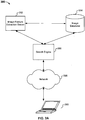
- FIG. 3A is a block diagram illustrating of an embodiment of an image feature extraction system.
- image feature extraction system 380 includes an image feature extraction server 382, which in some embodiments include one or more devices having one or more processors coupled to one or more memories.
- Image feature extraction server 382 includes one or more interfaces configured to receive user inputs; for example, user inputs sent by client devices such as 389 over a network 388, which may be the Internet or other communications network. Examples of a communication interface include, without limitation, external connections, such as a port, cable, wireline, or wireless network interface card, etc., and internal connections, such as a communication buses.
- the client device is a computing device such as a computer or mobile device with networking capabilities.
- Image feature exaction server 382 has access to an image database 384 that stores images.
- image feature extraction server 382 processes the image and extracts specific features of the image.
- a search engine 386 searches the content of image database 384 according to the image features extracted by image feature extraction server 382, and an image as a search result is returned.
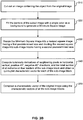
- FIG. 3B is a flowchart illustrating an embodiment of an image feature extraction process. The process may be performed on a system such as 380.
- an image containing an object of interest is cut out from an original image.
- an original image contains not only an object of interest but also a background.
- the background is often at the periphery of the original image and the object is often at the center of the original image.
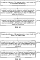
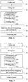
- FIG. 3C is a flowchart illustrating an embodiment of a process to find the left and right borders of an object.
- the sum of the grayscale values in each column for all pixels of the original image is computed. For example, for a 10 ⁇ 10 pixel image, each pixel has a grayscale value. The sum of the grayscale values of all 10 pixels in each column is computed and defined as the grayscale value of this column.
- the column grayscale value may be stored in an array.
- the differences between the grayscale values of two neighboring columns of the original image are computed from left to right, and an x-coordinate (x a ) of the column on the right is recorded when the difference is larger than a threshold.
- a threshold For example, the grayscale values of all columns stored in the array from process 311a is scanned from left to right, and differences between neighboring values in the array are computed sequentially.
- the scan reveals that the difference of the grayscale value between the second and the third column is 50, which is larger than a predetermined threshold va lue of 30, the x-coordinate x 3 of the third column is recorded, which corresponds to the index of the third element in the array.
- the x-coordinate of the column on the left may be recorded.
- the difference between the grayscale values of the second column and the third column is 50, which is larger than the predetermined threshold 30, the x-coordinate x 2 of the second column may be recorded, which corresponds to the index of the second element in the array. There is no difference in performance between these two embodiments.
- the differences between the grayscale values of two neighboring columns of the original im age are computed from right to left; and an x - coordinate x b of the column on the left is recorded when the difference is larger than a threshold. Therefore, the right border indicating the position of the object in the original image is detected.
- the thresholds at 312a and 313a can be determined from experience. For example, if the borders of an object differ significantly from the background when the difference in grayscale value is larger than a certain value, the value can be used as the threshold.
- FIG. 3D is a flowchart illustrating an embodiment of a process to find the top and bottom borders of an object.
- the sum of grayscale values in each row for all pixels of the original image is computed.
- the differences between the grayscale values of two neighboring rows of the original image are computed from top to bottom; and a y-coordinate y a of the row below is recorded when the difference is larger than a threshold.
- the differences between the grayscale value sums of two neighboring rows of the original image are computed from bottom to top; and a y-coordinate y b of the row above is recorded when the difference is larger than a threshold.
- top and bottom borders indicating the position of the object in the original image are detected, with one being y a and the other being y b .
- the foregoing embodiments cut out a rectangular image from the original image. It is simple and easy to use. In some embodiments, more complex processes of cutting out objects are used. For example, the grayscale value differences in two diagonal directions may also be computed. Therefore, the borders of the object in the two diagonal directions can then be detected. As a result, an octagonal cutout image containing the object in the original image can be detected. Similarly, a 16-gon, 32-gon, or 64-gon image cutout containing the object may also be obtained with additional directions.
- the original image may be horizontally divided into several sub-regions.
- the left and right borders of the object in each sub-region can be detected in the same manner as described above.
- the original image may also be vertically divided into several sub-regions.
- the top and bottom borders of the object in each sub-region can also be detected in the same manner. Accordingly, a polygon cutout image containing the object can be obtained.
- a square that has the shortest perimeter and contains the rectangular cutout image is obtained. It is referred to as a minimum square.
- the areas outside the borders of the cutout image and within the minimum square are then filled with a single color as the background.
- the single color may any RGB color. The color (0, 0, 0) is often used because it is simple and does not cause interference with the cutout image, making the subsequent computation of luminosity derivatives easier.
- FIG. 4A is a block diagram illustrating an embodiment of a minimum square obtained by a process to fill a cutout image.
- 402 is the cut out image from the original image
- 404 is the minimum square.
- the purpose of the single-color filling and Minimum-Square-obtaining of the cutout image is to make it easier to divide the cutout image containing the object into sub-image blocks having a predetermined size.
- the minimum square image is resized into a square image having a first predetermined size, then the resized image is divided into non-overlapping sub-image blocks having a second predetermined size.
- a minimum square image is resized into an image having 64 ⁇ 64 pixels or 128 ⁇ 128 pixels.
- the minimum square is resized into a square of a first predetermined size.
- the resized square image is divided into non-overlapping sub-image blocks having a second predetermined size, such as 16 ⁇ *16, 8 ⁇ 8, or 32 ⁇ 32 pixels.
- the first predetermined size may be 64 ⁇ 64 pixels and the second predetermined size may be 16 ⁇ 16 pixels; in this case the image including the object will be divided into 4 ⁇ 4 sub-image blocks.
- the purpose of this process is to normalize the square image containing the object so that the subsequent processing of the image may be standardized and simplified.
- Both the first and the second predetermined sizes are preset. As long as the preset sizes are reasonable, no substantive difference is made.
- the resized image may be divided into overlapped sub-image blocks.
- such division may increase the computational complexity and the dimensionality of the final output of the characteristic vector of the image.
- the luminosity derivatives of neighboring pixels in horizontal, vertical, positive 45°, and negative 45° directions of the sub-image are computed.
- the characteristic vector of a sub-image block can be obtained.
- a character vector of a sub-image block indicates the features of the sub-image block and it is defined by the numbers of extrema of the derivatives in the aforementioned four directions, and the total number of all extrema on the four borders of the sub-image block.
- the characteristic vector is a quintuplet vector in some embodiments, i.e., a vector with five elements, denoted as M ( a , b , c , d , e ).
- the quintuplet vector is initialized as M (0, 0, 0, 0, 0) in this example.
- luminosity derivatives can be computed.
- the value of luminosity may be obtained by a method known in the art, using the luminosity curve which describes the visual sensitivity of the human eye.
- a floating-point value in the range of 0 ⁇ 1 is mapped to an integer between 1 and 255.
- a luminosity derivative represents the change of luminosity between pixels.
- edges or boundaries of an object in an image can be detected based on the fact that edges or boundaries of the object significantly differ from other portions of the image in terms of luminosity; therefore, the shape of the object in the image can be represented in a numerical manner.
- the feature of an image can be described by the extrema of its luminosity derivatives.
- an extremum of the luminosity derivative is computed for all of the two neighboring pixels in a certain direction.
- a pixel is the extremum of the luminosity derivative if the sign of the luminosity derivative changes from its neighboring pixel.
- the point where the extremum is located is usually an edge between the object and other parts of the image, or the shape feature of one part of the object that differs from the shape feature of other parts.
- these extrema can be used to describe the shape features of the object.
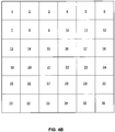
- FIG. 4B is a diagram illustrating an example sub-image block used in the luminosity derivative computation.
- the luminosity derivative in the horizontal direction is computed.
- luminosity derivatives of neighboring pixels (1, 2), (2, 3), (3,4), etc. are calculated.
- the luminosity derivative is simply the difference between the luminosity values of the neighboring pixels. If only one extremum of the luminosity derivative exists and it lies within the sub-image block, b is incremented by 1; if multiple extrema exist, b's value is equal to the number of the extrema; and if the extremum lies on the border of the sub-image block, a is incremented by 1.
- the luminosity derivatives of pixels may be the luminosity derivatives of pixels in two neighboring columns.
- the luminosity derivative in the vertical direction is also computed.
- luminosity derivatives of neighboring pixels (1, 7), (7, 13), (13, 19), etc. are calculated. If one extremum of the luminosity derivative exists and lies within the sub-image block, c is incremented by 1; if multiple extrema exist, c's value is equal to the number of extrema; and if the extremum lies on the border of the sub-image block, a is incremented by 1.
- the luminosity derivatives of pixels are the luminosity derivatives of pixels in two neighboring rows.
- the luminosity derivative in the positive 45° direction is computed.
- luminosity derivatives of neighboring pixels (2, 7), (3, 8), (4, 9), etc. are calculated. If one extremum of the luminosity derivative exists and lies within the sub-image block, d is incremented by 1; if multiple extrema exist, d 's value is equal to the number of extrema; and if the extremum lies on the border of the sub-image block, a is incremented by 1.
- the luminosity derivatives of pixels are the luminosity derivatives of pixels in the positive 45° direction.
- the luminosity derivative in the negative 45° direction is computed.
- luminosity derivatives of neighboring pixels (1, 8), (2, 9), (3, 10), etc. are calculated. If an extremum of the luminosity derivative exists and lies within the sub-image block, value 1 is added to e ; if multiple extrema exist, e 's value equals to the number of extrema; and if the extremum lies on the border of the sub-image block, value 1 is equal to a .
- the luminosity derivatives of pixels may be the luminosity derivative of pixels in the negative 45° direction.
- the values of a , b , c, d and e in the quintuplet vector representing the shape feature of the sub-image may be calculated differently in a different way.
- the quintuplet vector of each sub-image block is obtained.
- the vector represents the shape feature of each sub-image block.
- the characteristic quintuplet vectors of all sub-image blocks are represented as one characteristic vector of the original image.
- an image having 64 ⁇ 64 pixels after step 320 is divided into 4 ⁇ 4 pieces of non-overlapping blocks having 16 ⁇ 16 pixels.
- Each quintuplet vector represents the shape feature of a sub-image block.
- 16 quintuplet vectors are arranged to form an image characteristic vector with 80 elements, which represents the shape feature of the original image.
- the method may further include a normalization process.
- the length and width of the cutout image from the original image are compared. If the length is larger than the width, the image is rotated clockwise by 90°. The purpose of rotation is to arrange all images in the same orientation. For example, the shape of a pen in a picture can be vertical or horizontal, but it is easier to compare the shapes of pens in different pictures if the pens in the picture all have the same orientation.
- the image may be rotated counter-clockwise.
- the sum of the grayscale values of an upper half of the cutout image or the minimum square image and the sum of the grayscale values of a lower half of the cutout image or the minimum square image are compared. If the sum of the grayscale values of the upper half is larger than the sum of the grayscale values of the lower half, the cutout image or the minimum square image is inverted.
- the inversion method is also used to normalize the orientation of the object contained in an image.
- an upside-down apple is shown in an image; however, apples are upright in most pictures that contain apples. Therefore, in order to compare the picture with other pictures, the image with the upside-down apple should be inverted.
- the sum of the grayscale values of the upper half of the image is larger than the sum of grayscale values of the lower half of the image; and conversely, for an object with a smaller top and a larger bottom, the sum of grayscale values of the lower half of the image is larger than the sum of grayscale values of the upper half of the image.
- Only integer computing is involved in this embodiment, and no floating-point computing is involved; therefore, the processing speed may be significantly improved using the same hardware configuration.
- the processing speed can be improved because floating-point computing is not involved.
- existing multi-core processors are better suited to process divided images in parallel. Assuming an image of 200 ⁇ 200 pixels, all processing can be completed within 10 ms for the various embodiments of the application.
- the system processes multiple images and stores their corresponding characteristic vectors, the images, and any other relevant information such as information about products that corresponds to the images in the database.
- the characteristic vector of the image in question is looked up in the database. If a match is found, the image (or an identifier of the image) in the database with the matching characteristic vector is returned.
- FIG. 5 is a block diagram illustrating an embodiment of an image feature extraction system. As shown in the figure, the system includes:
- the normalization unit 53 further includes a rotation unit 533, adapted to compare the length and the width of the cutout image, and rotate the image by 90° if the length is larger than the width, as illustrated in FIG. 6 .
- the normalization unit 53 may further include an inversion unit 534, adapted to compare the sum of grayscale values of an upper half of the cutout image with the sum of the grayscale values of a lower half of the cutout image, and invert the image after filling the cutout image if the sum of grayscale values of the upper half is larger than the sum of grayscale values of the lower half, as illustrated in FIG. 7 .
- an inversion unit 534 adapted to compare the sum of grayscale values of an upper half of the cutout image with the sum of the grayscale values of a lower half of the cutout image, and invert the image after filling the cutout image if the sum of grayscale values of the upper half is larger than the sum of grayscale values of the lower half, as illustrated in FIG. 7 .
- the normalization unit 53 may include both the rotation unit 533 and the inversion unit 534 at the same time.
- the cutting unit 51 may cut out an image containing an object from an original image; in particular, it may cut out an image containing an object from the original image based on a significant difference in terms of grayscale values between an edge of the object and the background.
- the cutting process further includes:
- a device or a system could include one or more memories, an interface configured to receive a user input; and with one or more processors, coupled to the interface, the processors is/are configured to cut out an image containing an object from an original image; fill the borders of the cutout image with a single color as the background such that a minimum square is obtained; resize the minimum square image into a square image having a predetermined size, and divide the resized image into non-overlapping sub-image blocks having a second predetermined size; then compute the luminosity derivatives of two neighboring pixels in horizontal, vertical, positive 45°, and negative 45° directions, and define the characteristic vectors of each sub-image block by the respective numbers of the extrema of the derivatives in the four directions and the total number of all extrema on the four borders of the sub-image block; then compose the characteristic vectors of all sub-image blocks as one characteristic vector of the original image.
- the shape features of images can be extracted using the above device/system configuration. Compared with the
- the units described above can be implemented as software components executing on one or more general purpose processors, as hardware such as programmable logic devices and/or Application Specific Integrated Circuits designed to perform certain functions or a combination thereof.
- the units can be embodied by a form of software products which can be stored in a nonvolatile storage medium (such as optical disk, flash storage device, mobile hard disk, etc.), including a number of instructions for making a computer device (such as personal computers, servers, network equipments, etc.) implement the methods described in the embodiments of the present invention.
- the units may be implemented on a single device or distributed across multiple devices. The functions of the units may be merged into one another or further split into multiple sub-units.
- this application can be implemented with software and at least a hardware platform. Therefore, this application may be in the form of a computer program product that is implemented on one or more computer-usable storage media (including, without limitation, magnetic disk storage, CD-ROM, and optical storage) containing computer-usable program codes.
- computer-usable storage media including, without limitation, magnetic disk storage, CD-ROM, and optical storage
- image feature exaction methods in this application can be applied in many all-purpose or dedicated computer systems or configurations, such as personal computers, servers, handsets, or other portable devices, tablets, multi-server systems, microprocessor-based systems, set-top boxes, programmable consumer electric devices, network PCs, small computers, super computers, and distributed computing environments with any one of the above systems or devices.
- the embodiments of the application can be described in the context of computer-executable instructions executed by a computer, for example, a program module.
- the program module includes a routine, program, object, component, or data structure which performs certain functions or implements a particular abstract data type.
- the application may also be implemented in distributed computing environments, in which remote processing devices connected via communication networks are used to perform image feature extraction functions.
- the program module may be located in local and remote computer storage media including the local storage device.
Landscapes
- Engineering & Computer Science (AREA)
- Computer Vision & Pattern Recognition (AREA)
- Physics & Mathematics (AREA)
- General Physics & Mathematics (AREA)
- Theoretical Computer Science (AREA)
- Image Analysis (AREA)
- Image Processing (AREA)
Applications Claiming Priority (3)
| Application Number | Priority Date | Filing Date | Title |
|---|---|---|---|
| CN2009100072189A CN101477692B (zh) | 2009-02-13 | 2009-02-13 | 图像特征提取方法及装置 |
| US12/658,471 US8515178B2 (en) | 2009-02-13 | 2010-02-09 | Method and system for image feature extraction |
| PCT/US2010/000383 WO2010093447A1 (en) | 2009-02-13 | 2010-02-10 | Method and system for image feature extraction |
Publications (3)
| Publication Number | Publication Date |
|---|---|
| EP2396750A1 EP2396750A1 (en) | 2011-12-21 |
| EP2396750A4 EP2396750A4 (en) | 2018-01-10 |
| EP2396750B1 true EP2396750B1 (en) | 2020-06-17 |
Family
ID=40838400
Family Applications (1)
| Application Number | Title | Priority Date | Filing Date |
|---|---|---|---|
| EP10741513.5A Active EP2396750B1 (en) | 2009-02-13 | 2010-02-10 | Method and system for image feature extraction |
Country Status (5)
| Country | Link |
|---|---|
| US (2) | US8515178B2 (enExample) |
| EP (1) | EP2396750B1 (enExample) |
| JP (1) | JP5538435B2 (enExample) |
| CN (1) | CN101477692B (enExample) |
| WO (1) | WO2010093447A1 (enExample) |
Cited By (21)
| Publication number | Priority date | Publication date | Assignee | Title |
|---|---|---|---|---|
| US11403069B2 (en) | 2017-07-24 | 2022-08-02 | Tesla, Inc. | Accelerated mathematical engine |
| US11409692B2 (en) | 2017-07-24 | 2022-08-09 | Tesla, Inc. | Vector computational unit |
| US11487288B2 (en) | 2017-03-23 | 2022-11-01 | Tesla, Inc. | Data synthesis for autonomous control systems |
| US11537811B2 (en) | 2018-12-04 | 2022-12-27 | Tesla, Inc. | Enhanced object detection for autonomous vehicles based on field view |
| US11562231B2 (en) | 2018-09-03 | 2023-01-24 | Tesla, Inc. | Neural networks for embedded devices |
| US11561791B2 (en) | 2018-02-01 | 2023-01-24 | Tesla, Inc. | Vector computational unit receiving data elements in parallel from a last row of a computational array |
| US11567514B2 (en) | 2019-02-11 | 2023-01-31 | Tesla, Inc. | Autonomous and user controlled vehicle summon to a target |
| US11610117B2 (en) | 2018-12-27 | 2023-03-21 | Tesla, Inc. | System and method for adapting a neural network model on a hardware platform |
| US11636333B2 (en) | 2018-07-26 | 2023-04-25 | Tesla, Inc. | Optimizing neural network structures for embedded systems |
| US11665108B2 (en) | 2018-10-25 | 2023-05-30 | Tesla, Inc. | QoS manager for system on a chip communications |
| US11681649B2 (en) | 2017-07-24 | 2023-06-20 | Tesla, Inc. | Computational array microprocessor system using non-consecutive data formatting |
| US11734562B2 (en) | 2018-06-20 | 2023-08-22 | Tesla, Inc. | Data pipeline and deep learning system for autonomous driving |
| US11748620B2 (en) | 2019-02-01 | 2023-09-05 | Tesla, Inc. | Generating ground truth for machine learning from time series elements |
| US11790664B2 (en) | 2019-02-19 | 2023-10-17 | Tesla, Inc. | Estimating object properties using visual image data |
| US11816585B2 (en) | 2018-12-03 | 2023-11-14 | Tesla, Inc. | Machine learning models operating at different frequencies for autonomous vehicles |
| US11841434B2 (en) | 2018-07-20 | 2023-12-12 | Tesla, Inc. | Annotation cross-labeling for autonomous control systems |
| US11893774B2 (en) | 2018-10-11 | 2024-02-06 | Tesla, Inc. | Systems and methods for training machine models with augmented data |
| US11893393B2 (en) | 2017-07-24 | 2024-02-06 | Tesla, Inc. | Computational array microprocessor system with hardware arbiter managing memory requests |
| US12014553B2 (en) | 2019-02-01 | 2024-06-18 | Tesla, Inc. | Predicting three-dimensional features for autonomous driving |
| US12307350B2 (en) | 2018-01-04 | 2025-05-20 | Tesla, Inc. | Systems and methods for hardware-based pooling |
| US12462575B2 (en) | 2021-08-19 | 2025-11-04 | Tesla, Inc. | Vision-based machine learning model for autonomous driving with adjustable virtual camera |
Families Citing this family (17)
| Publication number | Priority date | Publication date | Assignee | Title |
|---|---|---|---|---|
| WO2011079412A1 (zh) * | 2009-12-29 | 2011-07-07 | 中国科学院自动化研究所 | 快速多算子的图像缩放方法 |
| KR101767269B1 (ko) * | 2011-04-25 | 2017-08-10 | 한국전자통신연구원 | 영상 검색 장치 및 방법 |
| US9501838B1 (en) | 2015-08-24 | 2016-11-22 | The Boeing Company | Systems and methods for determining boundaries of features in digital images |
| CN106485186B (zh) * | 2015-08-26 | 2020-02-18 | 阿里巴巴集团控股有限公司 | 图像特征提取方法、装置、终端设备及系统 |
| CN105447876B (zh) * | 2015-12-10 | 2017-02-15 | 北京中科紫鑫科技有限责任公司 | 一种dna测序的图像的磁珠提取方法及装置 |
| CN107944618B (zh) * | 2017-11-20 | 2020-03-20 | 阿里巴巴集团控股有限公司 | 共享车辆的布点规划方法、装置以及电子设备 |
| CN109816675A (zh) * | 2018-12-28 | 2019-05-28 | 歌尔股份有限公司 | 物体的检测方法、检测装置及存储介质 |
| CN110853120B (zh) * | 2019-10-09 | 2023-05-19 | 上海交通大学 | 基于分割绘图法的网络布局方法、系统及介质 |
| CN110751689A (zh) * | 2019-10-24 | 2020-02-04 | 南京农业大学 | 一种基于图像处理的梨果实横纵径测量方法 |
| CN110579174A (zh) * | 2019-10-24 | 2019-12-17 | 南京农业大学 | 一种基于机器视觉的梨果柄长度的测量方法 |
| CN111476799A (zh) * | 2020-03-23 | 2020-07-31 | 福建星网物联信息系统有限公司 | 一种图像分析方法及存储介质 |
| CN111651674B (zh) * | 2020-06-03 | 2023-08-25 | 北京妙医佳健康科技集团有限公司 | 双向搜索方法、装置及电子设备 |
| CN112017174B (zh) * | 2020-09-03 | 2024-05-31 | 湖南省华芯医疗器械有限公司 | 图像处理方法、装置、电子设备及存储介质 |
| US20240087285A1 (en) * | 2021-03-10 | 2024-03-14 | Detectsystem Lab A/S | Quantitative Image Analysis |
| CN112686340B (zh) * | 2021-03-12 | 2021-07-13 | 成都点泽智能科技有限公司 | 一种基于深度神经网络的密集小目标检测方法 |
| TWI767642B (zh) * | 2021-04-01 | 2022-06-11 | 環球晶圓股份有限公司 | 晶圓檢測方法及其裝置 |
| CN113554615B (zh) * | 2021-07-21 | 2023-08-22 | 网易(杭州)网络有限公司 | 一种图像精细化处理方法、装置、电子设备及存储介质 |
Family Cites Families (18)
| Publication number | Priority date | Publication date | Assignee | Title |
|---|---|---|---|---|
| JPH0334880A (ja) * | 1989-06-30 | 1991-02-14 | Intaadetsuku:Kk | 印刷文字の検査方法及びその装置 |
| JPH05210736A (ja) * | 1992-01-31 | 1993-08-20 | Olympus Optical Co Ltd | 画像輪郭抽出方法 |
| US20030009670A1 (en) * | 2001-04-02 | 2003-01-09 | Digimarc Corporation | Background watermark processing |
| US5973692A (en) * | 1997-03-10 | 1999-10-26 | Knowlton; Kenneth Charles | System for the capture and indexing of graphical representations of files, information sources and the like |
| JP4153108B2 (ja) * | 1998-10-29 | 2008-09-17 | 富士フイルム株式会社 | 画像処理方法、画像処理装置及び記録媒体 |
| JP2001319232A (ja) * | 2000-05-11 | 2001-11-16 | Fuji Xerox Co Ltd | 類似画像検索装置および類似画像検索方法 |
| JP3692500B2 (ja) * | 2000-09-12 | 2005-09-07 | インターナショナル・ビジネス・マシーンズ・コーポレーション | 画像処理方法、画像処理システムおよび記録媒体 |
| JP3586734B2 (ja) * | 2001-10-01 | 2004-11-10 | 学校法人高知工科大学 | 液晶流動形成機構、液晶流動形成方法および液晶流動を用いた物体移動機構 |
| JP2003122758A (ja) * | 2001-10-11 | 2003-04-25 | Canon Inc | 画像検索方法及び装置 |
| JP4016735B2 (ja) * | 2001-11-30 | 2007-12-05 | 株式会社日立製作所 | レーンマーク認識方法 |
| US7532753B2 (en) * | 2003-09-29 | 2009-05-12 | Lipsky Scott E | Method and system for specifying color of a fill area |
| US20060067592A1 (en) * | 2004-05-27 | 2006-03-30 | Walmsley Simon R | Configurable image processor |
| JP2006293949A (ja) * | 2005-03-17 | 2006-10-26 | Sharp Corp | 画像照合装置、画像照合方法、画像照合プログラムおよび画像照合プログラムを記録したコンピュータ読取り可能な記録媒体 |
| CN101371273A (zh) * | 2005-12-30 | 2009-02-18 | 意大利电信股份公司 | 视频序列的分割 |
| US7907791B2 (en) * | 2006-11-27 | 2011-03-15 | Tessera International, Inc. | Processing of mosaic images |
| JP4912206B2 (ja) * | 2007-04-18 | 2012-04-11 | 富士通株式会社 | 画像処理方法、画像処理装置、画像処理システム及びコンピュータプログラム |
| KR101023207B1 (ko) * | 2007-09-05 | 2011-03-18 | 한국전자통신연구원 | 영상 객체 추출 장치 및 그 방법 |
| KR100992362B1 (ko) * | 2008-12-11 | 2010-11-04 | 삼성전기주식회사 | 컬러 보간 장치 |
-
2009
- 2009-02-13 CN CN2009100072189A patent/CN101477692B/zh not_active Expired - Fee Related
-
2010
- 2010-02-09 US US12/658,471 patent/US8515178B2/en not_active Expired - Fee Related
- 2010-02-10 EP EP10741513.5A patent/EP2396750B1/en active Active
- 2010-02-10 WO PCT/US2010/000383 patent/WO2010093447A1/en not_active Ceased
- 2010-02-10 JP JP2011550127A patent/JP5538435B2/ja not_active Expired - Fee Related
-
2013
- 2013-07-17 US US13/944,677 patent/US9865063B2/en active Active
Non-Patent Citations (1)
| Title |
|---|
| None * |
Cited By (36)
| Publication number | Priority date | Publication date | Assignee | Title |
|---|---|---|---|---|
| US11487288B2 (en) | 2017-03-23 | 2022-11-01 | Tesla, Inc. | Data synthesis for autonomous control systems |
| US12020476B2 (en) | 2017-03-23 | 2024-06-25 | Tesla, Inc. | Data synthesis for autonomous control systems |
| US11403069B2 (en) | 2017-07-24 | 2022-08-02 | Tesla, Inc. | Accelerated mathematical engine |
| US11409692B2 (en) | 2017-07-24 | 2022-08-09 | Tesla, Inc. | Vector computational unit |
| US11893393B2 (en) | 2017-07-24 | 2024-02-06 | Tesla, Inc. | Computational array microprocessor system with hardware arbiter managing memory requests |
| US12086097B2 (en) | 2017-07-24 | 2024-09-10 | Tesla, Inc. | Vector computational unit |
| US12216610B2 (en) | 2017-07-24 | 2025-02-04 | Tesla, Inc. | Computational array microprocessor system using non-consecutive data formatting |
| US11681649B2 (en) | 2017-07-24 | 2023-06-20 | Tesla, Inc. | Computational array microprocessor system using non-consecutive data formatting |
| US12307350B2 (en) | 2018-01-04 | 2025-05-20 | Tesla, Inc. | Systems and methods for hardware-based pooling |
| US11561791B2 (en) | 2018-02-01 | 2023-01-24 | Tesla, Inc. | Vector computational unit receiving data elements in parallel from a last row of a computational array |
| US11797304B2 (en) | 2018-02-01 | 2023-10-24 | Tesla, Inc. | Instruction set architecture for a vector computational unit |
| US12455739B2 (en) | 2018-02-01 | 2025-10-28 | Tesla, Inc. | Instruction set architecture for a vector computational unit |
| US11734562B2 (en) | 2018-06-20 | 2023-08-22 | Tesla, Inc. | Data pipeline and deep learning system for autonomous driving |
| US11841434B2 (en) | 2018-07-20 | 2023-12-12 | Tesla, Inc. | Annotation cross-labeling for autonomous control systems |
| US11636333B2 (en) | 2018-07-26 | 2023-04-25 | Tesla, Inc. | Optimizing neural network structures for embedded systems |
| US12079723B2 (en) | 2018-07-26 | 2024-09-03 | Tesla, Inc. | Optimizing neural network structures for embedded systems |
| US12346816B2 (en) | 2018-09-03 | 2025-07-01 | Tesla, Inc. | Neural networks for embedded devices |
| US11983630B2 (en) | 2018-09-03 | 2024-05-14 | Tesla, Inc. | Neural networks for embedded devices |
| US11562231B2 (en) | 2018-09-03 | 2023-01-24 | Tesla, Inc. | Neural networks for embedded devices |
| US11893774B2 (en) | 2018-10-11 | 2024-02-06 | Tesla, Inc. | Systems and methods for training machine models with augmented data |
| US11665108B2 (en) | 2018-10-25 | 2023-05-30 | Tesla, Inc. | QoS manager for system on a chip communications |
| US12367405B2 (en) | 2018-12-03 | 2025-07-22 | Tesla, Inc. | Machine learning models operating at different frequencies for autonomous vehicles |
| US11816585B2 (en) | 2018-12-03 | 2023-11-14 | Tesla, Inc. | Machine learning models operating at different frequencies for autonomous vehicles |
| US11908171B2 (en) | 2018-12-04 | 2024-02-20 | Tesla, Inc. | Enhanced object detection for autonomous vehicles based on field view |
| US12198396B2 (en) | 2018-12-04 | 2025-01-14 | Tesla, Inc. | Enhanced object detection for autonomous vehicles based on field view |
| US11537811B2 (en) | 2018-12-04 | 2022-12-27 | Tesla, Inc. | Enhanced object detection for autonomous vehicles based on field view |
| US12136030B2 (en) | 2018-12-27 | 2024-11-05 | Tesla, Inc. | System and method for adapting a neural network model on a hardware platform |
| US11610117B2 (en) | 2018-12-27 | 2023-03-21 | Tesla, Inc. | System and method for adapting a neural network model on a hardware platform |
| US12014553B2 (en) | 2019-02-01 | 2024-06-18 | Tesla, Inc. | Predicting three-dimensional features for autonomous driving |
| US11748620B2 (en) | 2019-02-01 | 2023-09-05 | Tesla, Inc. | Generating ground truth for machine learning from time series elements |
| US12223428B2 (en) | 2019-02-01 | 2025-02-11 | Tesla, Inc. | Generating ground truth for machine learning from time series elements |
| US12164310B2 (en) | 2019-02-11 | 2024-12-10 | Tesla, Inc. | Autonomous and user controlled vehicle summon to a target |
| US11567514B2 (en) | 2019-02-11 | 2023-01-31 | Tesla, Inc. | Autonomous and user controlled vehicle summon to a target |
| US11790664B2 (en) | 2019-02-19 | 2023-10-17 | Tesla, Inc. | Estimating object properties using visual image data |
| US12236689B2 (en) | 2019-02-19 | 2025-02-25 | Tesla, Inc. | Estimating object properties using visual image data |
| US12462575B2 (en) | 2021-08-19 | 2025-11-04 | Tesla, Inc. | Vision-based machine learning model for autonomous driving with adjustable virtual camera |
Also Published As
| Publication number | Publication date |
|---|---|
| US20100208988A1 (en) | 2010-08-19 |
| US8515178B2 (en) | 2013-08-20 |
| EP2396750A1 (en) | 2011-12-21 |
| CN101477692B (zh) | 2012-08-22 |
| US20130301914A1 (en) | 2013-11-14 |
| CN101477692A (zh) | 2009-07-08 |
| JP5538435B2 (ja) | 2014-07-02 |
| EP2396750A4 (en) | 2018-01-10 |
| US9865063B2 (en) | 2018-01-09 |
| HK1132826A1 (en) | 2010-03-05 |
| WO2010093447A1 (en) | 2010-08-19 |
| JP2012518223A (ja) | 2012-08-09 |
Similar Documents
| Publication | Publication Date | Title |
|---|---|---|
| EP2396750B1 (en) | Method and system for image feature extraction | |
| EP2711670B1 (en) | Visual localisation | |
| CN110622177B (zh) | 实例分割 | |
| CN102282572B (zh) | 表示图像块的方法和系统 | |
| US11704357B2 (en) | Shape-based graphics search | |
| US10262229B1 (en) | Wide-area salient object detection architecture for low power hardware platforms | |
| WO2019226366A1 (en) | Lighting estimation | |
| US20150206319A1 (en) | Digital image edge detection | |
| US10134149B2 (en) | Image processing | |
| WO2019019595A1 (zh) | 图片匹配方法及电子设备方法、装置、电子设备及介质 | |
| CN114758145A (zh) | 一种图像脱敏方法、装置、电子设备及存储介质 | |
| CN113537254A (zh) | 图像特征提取方法、装置、电子设备及可读存储介质 | |
| US9171227B2 (en) | Apparatus and method extracting feature information of a source image | |
| Shi et al. | Segment-based adaptive window and multi-feature fusion for stereo matching | |
| Feng et al. | HOSO: Histogram of surface orientation for RGB-D salient object detection | |
| JP7677429B2 (ja) | メディアコンテンツのオーバーレイに適した画像スペースの検出 | |
| Arun et al. | Cellular neural network–based hybrid approach toward automatic image registration | |
| CN114565872A (zh) | 视频数据处理方法、装置、设备及计算机可读存储介质 | |
| CN116266411A (zh) | 一种人脸识别方法、处理器、芯片、电子设备和存储介质 | |
| EP2884427A1 (en) | Method and system for describing an image | |
| Gupta et al. | Image feature detection using an improved implementation of maximally stable extremal regions for augmented reality applications | |
| WO2015162027A2 (en) | Method, device, user equipment and computer program for object extraction from multimedia content | |
| Yue et al. | Image denoising using cloud images | |
| CN117152774A (zh) | 图像搜索方法及装置、电子设备和可读存储介质 | |
| Zhang et al. | Joint shape and color descriptors for 3D urban model retrieval |
Legal Events
| Date | Code | Title | Description |
|---|---|---|---|
| PUAI | Public reference made under article 153(3) epc to a published international application that has entered the european phase |
Free format text: ORIGINAL CODE: 0009012 |
|
| 17P | Request for examination filed |
Effective date: 20110831 |
|
| AK | Designated contracting states |
Kind code of ref document: A1 Designated state(s): AT BE BG CH CY CZ DE DK EE ES FI FR GB GR HR HU IE IS IT LI LT LU LV MC MK MT NL NO PL PT RO SE SI SK SM TR |
|
| DAX | Request for extension of the european patent (deleted) | ||
| RA4 | Supplementary search report drawn up and despatched (corrected) |
Effective date: 20171211 |
|
| RIC1 | Information provided on ipc code assigned before grant |
Ipc: G06K 9/48 20060101AFI20171205BHEP Ipc: G06T 7/12 20170101ALI20171205BHEP |
|
| RIC1 | Information provided on ipc code assigned before grant |
Ipc: G06K 9/48 20060101AFI20191129BHEP Ipc: G06T 7/12 20170101ALI20191129BHEP |
|
| GRAP | Despatch of communication of intention to grant a patent |
Free format text: ORIGINAL CODE: EPIDOSNIGR1 |
|
| STAA | Information on the status of an ep patent application or granted ep patent |
Free format text: STATUS: GRANT OF PATENT IS INTENDED |
|
| INTG | Intention to grant announced |
Effective date: 20200117 |
|
| GRAS | Grant fee paid |
Free format text: ORIGINAL CODE: EPIDOSNIGR3 |
|
| GRAA | (expected) grant |
Free format text: ORIGINAL CODE: 0009210 |
|
| STAA | Information on the status of an ep patent application or granted ep patent |
Free format text: STATUS: THE PATENT HAS BEEN GRANTED |
|
| AK | Designated contracting states |
Kind code of ref document: B1 Designated state(s): AT BE BG CH CY CZ DE DK EE ES FI FR GB GR HR HU IE IS IT LI LT LU LV MC MK MT NL NO PL PT RO SE SI SK SM TR |
|
| REG | Reference to a national code |
Ref country code: GB Ref legal event code: FG4D |
|
| REG | Reference to a national code |
Ref country code: CH Ref legal event code: EP |
|
| REG | Reference to a national code |
Ref country code: IE Ref legal event code: FG4D |
|
| REG | Reference to a national code |
Ref country code: DE Ref legal event code: R096 Ref document number: 602010064638 Country of ref document: DE |
|
| REG | Reference to a national code |
Ref country code: AT Ref legal event code: REF Ref document number: 1282245 Country of ref document: AT Kind code of ref document: T Effective date: 20200715 |
|
| PG25 | Lapsed in a contracting state [announced via postgrant information from national office to epo] |
Ref country code: LT Free format text: LAPSE BECAUSE OF FAILURE TO SUBMIT A TRANSLATION OF THE DESCRIPTION OR TO PAY THE FEE WITHIN THE PRESCRIBED TIME-LIMIT Effective date: 20200617 Ref country code: SE Free format text: LAPSE BECAUSE OF FAILURE TO SUBMIT A TRANSLATION OF THE DESCRIPTION OR TO PAY THE FEE WITHIN THE PRESCRIBED TIME-LIMIT Effective date: 20200617 Ref country code: NO Free format text: LAPSE BECAUSE OF FAILURE TO SUBMIT A TRANSLATION OF THE DESCRIPTION OR TO PAY THE FEE WITHIN THE PRESCRIBED TIME-LIMIT Effective date: 20200917 Ref country code: FI Free format text: LAPSE BECAUSE OF FAILURE TO SUBMIT A TRANSLATION OF THE DESCRIPTION OR TO PAY THE FEE WITHIN THE PRESCRIBED TIME-LIMIT Effective date: 20200617 Ref country code: GR Free format text: LAPSE BECAUSE OF FAILURE TO SUBMIT A TRANSLATION OF THE DESCRIPTION OR TO PAY THE FEE WITHIN THE PRESCRIBED TIME-LIMIT Effective date: 20200918 |
|
| REG | Reference to a national code |
Ref country code: LT Ref legal event code: MG4D |
|
| REG | Reference to a national code |
Ref country code: NL Ref legal event code: MP Effective date: 20200617 |
|
| PG25 | Lapsed in a contracting state [announced via postgrant information from national office to epo] |
Ref country code: HR Free format text: LAPSE BECAUSE OF FAILURE TO SUBMIT A TRANSLATION OF THE DESCRIPTION OR TO PAY THE FEE WITHIN THE PRESCRIBED TIME-LIMIT Effective date: 20200617 Ref country code: LV Free format text: LAPSE BECAUSE OF FAILURE TO SUBMIT A TRANSLATION OF THE DESCRIPTION OR TO PAY THE FEE WITHIN THE PRESCRIBED TIME-LIMIT Effective date: 20200617 Ref country code: BG Free format text: LAPSE BECAUSE OF FAILURE TO SUBMIT A TRANSLATION OF THE DESCRIPTION OR TO PAY THE FEE WITHIN THE PRESCRIBED TIME-LIMIT Effective date: 20200917 |
|
| REG | Reference to a national code |
Ref country code: AT Ref legal event code: MK05 Ref document number: 1282245 Country of ref document: AT Kind code of ref document: T Effective date: 20200617 |
|
| PG25 | Lapsed in a contracting state [announced via postgrant information from national office to epo] |
Ref country code: NL Free format text: LAPSE BECAUSE OF FAILURE TO SUBMIT A TRANSLATION OF THE DESCRIPTION OR TO PAY THE FEE WITHIN THE PRESCRIBED TIME-LIMIT Effective date: 20200617 |
|
| PG25 | Lapsed in a contracting state [announced via postgrant information from national office to epo] |
Ref country code: RO Free format text: LAPSE BECAUSE OF FAILURE TO SUBMIT A TRANSLATION OF THE DESCRIPTION OR TO PAY THE FEE WITHIN THE PRESCRIBED TIME-LIMIT Effective date: 20200617 Ref country code: CZ Free format text: LAPSE BECAUSE OF FAILURE TO SUBMIT A TRANSLATION OF THE DESCRIPTION OR TO PAY THE FEE WITHIN THE PRESCRIBED TIME-LIMIT Effective date: 20200617 Ref country code: ES Free format text: LAPSE BECAUSE OF FAILURE TO SUBMIT A TRANSLATION OF THE DESCRIPTION OR TO PAY THE FEE WITHIN THE PRESCRIBED TIME-LIMIT Effective date: 20200617 Ref country code: IT Free format text: LAPSE BECAUSE OF FAILURE TO SUBMIT A TRANSLATION OF THE DESCRIPTION OR TO PAY THE FEE WITHIN THE PRESCRIBED TIME-LIMIT Effective date: 20200617 Ref country code: PT Free format text: LAPSE BECAUSE OF FAILURE TO SUBMIT A TRANSLATION OF THE DESCRIPTION OR TO PAY THE FEE WITHIN THE PRESCRIBED TIME-LIMIT Effective date: 20201019 Ref country code: SM Free format text: LAPSE BECAUSE OF FAILURE TO SUBMIT A TRANSLATION OF THE DESCRIPTION OR TO PAY THE FEE WITHIN THE PRESCRIBED TIME-LIMIT Effective date: 20200617 Ref country code: AT Free format text: LAPSE BECAUSE OF FAILURE TO SUBMIT A TRANSLATION OF THE DESCRIPTION OR TO PAY THE FEE WITHIN THE PRESCRIBED TIME-LIMIT Effective date: 20200617 Ref country code: EE Free format text: LAPSE BECAUSE OF FAILURE TO SUBMIT A TRANSLATION OF THE DESCRIPTION OR TO PAY THE FEE WITHIN THE PRESCRIBED TIME-LIMIT Effective date: 20200617 |
|
| PG25 | Lapsed in a contracting state [announced via postgrant information from national office to epo] |
Ref country code: IS Free format text: LAPSE BECAUSE OF FAILURE TO SUBMIT A TRANSLATION OF THE DESCRIPTION OR TO PAY THE FEE WITHIN THE PRESCRIBED TIME-LIMIT Effective date: 20201017 Ref country code: SK Free format text: LAPSE BECAUSE OF FAILURE TO SUBMIT A TRANSLATION OF THE DESCRIPTION OR TO PAY THE FEE WITHIN THE PRESCRIBED TIME-LIMIT Effective date: 20200617 Ref country code: PL Free format text: LAPSE BECAUSE OF FAILURE TO SUBMIT A TRANSLATION OF THE DESCRIPTION OR TO PAY THE FEE WITHIN THE PRESCRIBED TIME-LIMIT Effective date: 20200617 |
|
| REG | Reference to a national code |
Ref country code: DE Ref legal event code: R097 Ref document number: 602010064638 Country of ref document: DE |
|
| PLBE | No opposition filed within time limit |
Free format text: ORIGINAL CODE: 0009261 |
|
| STAA | Information on the status of an ep patent application or granted ep patent |
Free format text: STATUS: NO OPPOSITION FILED WITHIN TIME LIMIT |
|
| PG25 | Lapsed in a contracting state [announced via postgrant information from national office to epo] |
Ref country code: DK Free format text: LAPSE BECAUSE OF FAILURE TO SUBMIT A TRANSLATION OF THE DESCRIPTION OR TO PAY THE FEE WITHIN THE PRESCRIBED TIME-LIMIT Effective date: 20200617 |
|
| 26N | No opposition filed |
Effective date: 20210318 |
|
| PG25 | Lapsed in a contracting state [announced via postgrant information from national office to epo] |
Ref country code: SI Free format text: LAPSE BECAUSE OF FAILURE TO SUBMIT A TRANSLATION OF THE DESCRIPTION OR TO PAY THE FEE WITHIN THE PRESCRIBED TIME-LIMIT Effective date: 20200617 |
|
| PG25 | Lapsed in a contracting state [announced via postgrant information from national office to epo] |
Ref country code: MC Free format text: LAPSE BECAUSE OF FAILURE TO SUBMIT A TRANSLATION OF THE DESCRIPTION OR TO PAY THE FEE WITHIN THE PRESCRIBED TIME-LIMIT Effective date: 20200617 |
|
| REG | Reference to a national code |
Ref country code: BE Ref legal event code: MM Effective date: 20210228 |
|
| PG25 | Lapsed in a contracting state [announced via postgrant information from national office to epo] |
Ref country code: LU Free format text: LAPSE BECAUSE OF NON-PAYMENT OF DUE FEES Effective date: 20210210 Ref country code: LI Free format text: LAPSE BECAUSE OF NON-PAYMENT OF DUE FEES Effective date: 20210228 Ref country code: CH Free format text: LAPSE BECAUSE OF NON-PAYMENT OF DUE FEES Effective date: 20210228 |
|
| REG | Reference to a national code |
Ref country code: DE Ref legal event code: R079 Ref document number: 602010064638 Country of ref document: DE Free format text: PREVIOUS MAIN CLASS: G06K0009480000 Ipc: G06V0030182000 |
|
| PG25 | Lapsed in a contracting state [announced via postgrant information from national office to epo] |
Ref country code: IE Free format text: LAPSE BECAUSE OF NON-PAYMENT OF DUE FEES Effective date: 20210210 |
|
| PG25 | Lapsed in a contracting state [announced via postgrant information from national office to epo] |
Ref country code: BE Free format text: LAPSE BECAUSE OF NON-PAYMENT OF DUE FEES Effective date: 20210228 |
|
| PG25 | Lapsed in a contracting state [announced via postgrant information from national office to epo] |
Ref country code: HU Free format text: LAPSE BECAUSE OF FAILURE TO SUBMIT A TRANSLATION OF THE DESCRIPTION OR TO PAY THE FEE WITHIN THE PRESCRIBED TIME-LIMIT; INVALID AB INITIO Effective date: 20100210 Ref country code: CY Free format text: LAPSE BECAUSE OF FAILURE TO SUBMIT A TRANSLATION OF THE DESCRIPTION OR TO PAY THE FEE WITHIN THE PRESCRIBED TIME-LIMIT Effective date: 20200617 |
|
| P01 | Opt-out of the competence of the unified patent court (upc) registered |
Effective date: 20230418 |
|
| PG25 | Lapsed in a contracting state [announced via postgrant information from national office to epo] |
Ref country code: MK Free format text: LAPSE BECAUSE OF FAILURE TO SUBMIT A TRANSLATION OF THE DESCRIPTION OR TO PAY THE FEE WITHIN THE PRESCRIBED TIME-LIMIT Effective date: 20200617 |
|
| PG25 | Lapsed in a contracting state [announced via postgrant information from national office to epo] |
Ref country code: TR Free format text: LAPSE BECAUSE OF FAILURE TO SUBMIT A TRANSLATION OF THE DESCRIPTION OR TO PAY THE FEE WITHIN THE PRESCRIBED TIME-LIMIT Effective date: 20200617 |
|
| PG25 | Lapsed in a contracting state [announced via postgrant information from national office to epo] |
Ref country code: MT Free format text: LAPSE BECAUSE OF FAILURE TO SUBMIT A TRANSLATION OF THE DESCRIPTION OR TO PAY THE FEE WITHIN THE PRESCRIBED TIME-LIMIT Effective date: 20200617 |
|
| PGFP | Annual fee paid to national office [announced via postgrant information from national office to epo] |
Ref country code: DE Payment date: 20250227 Year of fee payment: 16 |
|
| PGFP | Annual fee paid to national office [announced via postgrant information from national office to epo] |
Ref country code: FR Payment date: 20250225 Year of fee payment: 16 |
|
| PGFP | Annual fee paid to national office [announced via postgrant information from national office to epo] |
Ref country code: GB Payment date: 20250227 Year of fee payment: 16 |