EP2396606B1 - Heat pipe assembly for solar collectors - Google Patents
Heat pipe assembly for solar collectors Download PDFInfo
- Publication number
- EP2396606B1 EP2396606B1 EP10707328.0A EP10707328A EP2396606B1 EP 2396606 B1 EP2396606 B1 EP 2396606B1 EP 10707328 A EP10707328 A EP 10707328A EP 2396606 B1 EP2396606 B1 EP 2396606B1
- Authority
- EP
- European Patent Office
- Prior art keywords
- heat
- heat pipes
- heat pipe
- solar collectors
- solar
- Prior art date
- Legal status (The legal status is an assumption and is not a legal conclusion. Google has not performed a legal analysis and makes no representation as to the accuracy of the status listed.)
- Active
Links
- 239000012530 fluid Substances 0.000 claims description 37
- 238000004519 manufacturing process Methods 0.000 claims description 36
- XLYOFNOQVPJJNP-UHFFFAOYSA-N water Substances O XLYOFNOQVPJJNP-UHFFFAOYSA-N 0.000 claims description 25
- 238000010521 absorption reaction Methods 0.000 claims description 17
- 238000010438 heat treatment Methods 0.000 claims description 12
- 238000005520 cutting process Methods 0.000 claims description 10
- 230000005611 electricity Effects 0.000 claims description 10
- 230000005855 radiation Effects 0.000 claims description 10
- 239000013529 heat transfer fluid Substances 0.000 claims description 9
- 238000000034 method Methods 0.000 claims description 9
- 229910052782 aluminium Inorganic materials 0.000 claims description 4
- XAGFODPZIPBFFR-UHFFFAOYSA-N aluminium Chemical compound [Al] XAGFODPZIPBFFR-UHFFFAOYSA-N 0.000 claims description 4
- 238000001704 evaporation Methods 0.000 claims description 3
- 239000004411 aluminium Substances 0.000 claims description 2
- 229910052751 metal Inorganic materials 0.000 claims description 2
- 239000002184 metal Substances 0.000 claims description 2
- 238000003466 welding Methods 0.000 claims 1
- 239000002826 coolant Substances 0.000 description 8
- 238000009434 installation Methods 0.000 description 8
- 238000009413 insulation Methods 0.000 description 7
- 239000007788 liquid Substances 0.000 description 6
- 238000003860 storage Methods 0.000 description 5
- OKKJLVBELUTLKV-UHFFFAOYSA-N Methanol Chemical compound OC OKKJLVBELUTLKV-UHFFFAOYSA-N 0.000 description 3
- 238000009792 diffusion process Methods 0.000 description 3
- 230000000694 effects Effects 0.000 description 3
- 238000005098 hot rolling Methods 0.000 description 3
- 238000002347 injection Methods 0.000 description 3
- 239000007924 injection Substances 0.000 description 3
- LFQSCWFLJHTTHZ-UHFFFAOYSA-N Ethanol Chemical compound CCO LFQSCWFLJHTTHZ-UHFFFAOYSA-N 0.000 description 2
- 238000000151 deposition Methods 0.000 description 2
- 238000007731 hot pressing Methods 0.000 description 2
- 238000002955 isolation Methods 0.000 description 2
- 239000003507 refrigerant Substances 0.000 description 2
- 230000005457 Black-body radiation Effects 0.000 description 1
- QLJCFNUYUJEXET-UHFFFAOYSA-K aluminum;trinitrite Chemical compound [Al+3].[O-]N=O.[O-]N=O.[O-]N=O QLJCFNUYUJEXET-UHFFFAOYSA-K 0.000 description 1
- 239000000872 buffer Substances 0.000 description 1
- 239000011521 glass Substances 0.000 description 1
- 238000003698 laser cutting Methods 0.000 description 1
- 239000011159 matrix material Substances 0.000 description 1
- 201000009240 nasopharyngitis Diseases 0.000 description 1
- 238000007650 screen-printing Methods 0.000 description 1
- 238000007789 sealing Methods 0.000 description 1
- 238000010008 shearing Methods 0.000 description 1
- 239000000126 substance Substances 0.000 description 1
Images


Classifications
-
- F—MECHANICAL ENGINEERING; LIGHTING; HEATING; WEAPONS; BLASTING
- F28—HEAT EXCHANGE IN GENERAL
- F28D—HEAT-EXCHANGE APPARATUS, NOT PROVIDED FOR IN ANOTHER SUBCLASS, IN WHICH THE HEAT-EXCHANGE MEDIA DO NOT COME INTO DIRECT CONTACT
- F28D15/00—Heat-exchange apparatus with the intermediate heat-transfer medium in closed tubes passing into or through the conduit walls ; Heat-exchange apparatus employing intermediate heat-transfer medium or bodies
- F28D15/02—Heat-exchange apparatus with the intermediate heat-transfer medium in closed tubes passing into or through the conduit walls ; Heat-exchange apparatus employing intermediate heat-transfer medium or bodies in which the medium condenses and evaporates, e.g. heat pipes
- F28D15/0266—Heat-exchange apparatus with the intermediate heat-transfer medium in closed tubes passing into or through the conduit walls ; Heat-exchange apparatus employing intermediate heat-transfer medium or bodies in which the medium condenses and evaporates, e.g. heat pipes with separate evaporating and condensing chambers connected by at least one conduit; Loop-type heat pipes; with multiple or common evaporating or condensing chambers
-
- F—MECHANICAL ENGINEERING; LIGHTING; HEATING; WEAPONS; BLASTING
- F24—HEATING; RANGES; VENTILATING
- F24S—SOLAR HEAT COLLECTORS; SOLAR HEAT SYSTEMS
- F24S10/00—Solar heat collectors using working fluids
- F24S10/40—Solar heat collectors using working fluids in absorbing elements surrounded by transparent enclosures, e.g. evacuated solar collectors
- F24S10/45—Solar heat collectors using working fluids in absorbing elements surrounded by transparent enclosures, e.g. evacuated solar collectors the enclosure being cylindrical
-
- F—MECHANICAL ENGINEERING; LIGHTING; HEATING; WEAPONS; BLASTING
- F24—HEATING; RANGES; VENTILATING
- F24S—SOLAR HEAT COLLECTORS; SOLAR HEAT SYSTEMS
- F24S10/00—Solar heat collectors using working fluids
- F24S10/90—Solar heat collectors using working fluids using internal thermosiphonic circulation
- F24S10/95—Solar heat collectors using working fluids using internal thermosiphonic circulation having evaporator sections and condenser sections, e.g. heat pipes
-
- F—MECHANICAL ENGINEERING; LIGHTING; HEATING; WEAPONS; BLASTING
- F28—HEAT EXCHANGE IN GENERAL
- F28D—HEAT-EXCHANGE APPARATUS, NOT PROVIDED FOR IN ANOTHER SUBCLASS, IN WHICH THE HEAT-EXCHANGE MEDIA DO NOT COME INTO DIRECT CONTACT
- F28D15/00—Heat-exchange apparatus with the intermediate heat-transfer medium in closed tubes passing into or through the conduit walls ; Heat-exchange apparatus employing intermediate heat-transfer medium or bodies
- F28D15/02—Heat-exchange apparatus with the intermediate heat-transfer medium in closed tubes passing into or through the conduit walls ; Heat-exchange apparatus employing intermediate heat-transfer medium or bodies in which the medium condenses and evaporates, e.g. heat pipes
- F28D15/0275—Arrangements for coupling heat-pipes together or with other structures, e.g. with base blocks; Heat pipe cores
-
- F—MECHANICAL ENGINEERING; LIGHTING; HEATING; WEAPONS; BLASTING
- F28—HEAT EXCHANGE IN GENERAL
- F28D—HEAT-EXCHANGE APPARATUS, NOT PROVIDED FOR IN ANOTHER SUBCLASS, IN WHICH THE HEAT-EXCHANGE MEDIA DO NOT COME INTO DIRECT CONTACT
- F28D15/00—Heat-exchange apparatus with the intermediate heat-transfer medium in closed tubes passing into or through the conduit walls ; Heat-exchange apparatus employing intermediate heat-transfer medium or bodies
- F28D15/02—Heat-exchange apparatus with the intermediate heat-transfer medium in closed tubes passing into or through the conduit walls ; Heat-exchange apparatus employing intermediate heat-transfer medium or bodies in which the medium condenses and evaporates, e.g. heat pipes
- F28D15/0283—Means for filling or sealing heat pipes
-
- Y—GENERAL TAGGING OF NEW TECHNOLOGICAL DEVELOPMENTS; GENERAL TAGGING OF CROSS-SECTIONAL TECHNOLOGIES SPANNING OVER SEVERAL SECTIONS OF THE IPC; TECHNICAL SUBJECTS COVERED BY FORMER USPC CROSS-REFERENCE ART COLLECTIONS [XRACs] AND DIGESTS
- Y02—TECHNOLOGIES OR APPLICATIONS FOR MITIGATION OR ADAPTATION AGAINST CLIMATE CHANGE
- Y02E—REDUCTION OF GREENHOUSE GAS [GHG] EMISSIONS, RELATED TO ENERGY GENERATION, TRANSMISSION OR DISTRIBUTION
- Y02E10/00—Energy generation through renewable energy sources
- Y02E10/40—Solar thermal energy, e.g. solar towers
- Y02E10/44—Heat exchange systems
-
- Y—GENERAL TAGGING OF NEW TECHNOLOGICAL DEVELOPMENTS; GENERAL TAGGING OF CROSS-SECTIONAL TECHNOLOGIES SPANNING OVER SEVERAL SECTIONS OF THE IPC; TECHNICAL SUBJECTS COVERED BY FORMER USPC CROSS-REFERENCE ART COLLECTIONS [XRACs] AND DIGESTS
- Y02—TECHNOLOGIES OR APPLICATIONS FOR MITIGATION OR ADAPTATION AGAINST CLIMATE CHANGE
- Y02E—REDUCTION OF GREENHOUSE GAS [GHG] EMISSIONS, RELATED TO ENERGY GENERATION, TRANSMISSION OR DISTRIBUTION
- Y02E10/00—Energy generation through renewable energy sources
- Y02E10/40—Solar thermal energy, e.g. solar towers
- Y02E10/46—Conversion of thermal power into mechanical power, e.g. Rankine, Stirling or solar thermal engines
-
- Y—GENERAL TAGGING OF NEW TECHNOLOGICAL DEVELOPMENTS; GENERAL TAGGING OF CROSS-SECTIONAL TECHNOLOGIES SPANNING OVER SEVERAL SECTIONS OF THE IPC; TECHNICAL SUBJECTS COVERED BY FORMER USPC CROSS-REFERENCE ART COLLECTIONS [XRACs] AND DIGESTS
- Y10—TECHNICAL SUBJECTS COVERED BY FORMER USPC
- Y10T—TECHNICAL SUBJECTS COVERED BY FORMER US CLASSIFICATION
- Y10T29/00—Metal working
- Y10T29/49—Method of mechanical manufacture
- Y10T29/4935—Heat exchanger or boiler making
- Y10T29/49353—Heat pipe device making
Definitions
- the present invention relates to a set of heat pipes for solar collectors, of the type comprising a plurality of heat pipes, each heat pipe being adapted to be arranged in a respective solar collector, and comprising a heat pipe fluid, a first sheet and a second sheet locally. merged together and delimiting a reservoir, the reservoir containing the heat pipe fluid, extending over a hot evaporating portion of the heat pipe fluid and a cold condensing portion of the heat pipe fluid, and being formed by a gap between the two leaves such a set is known from the document JP 2003042572 .
- the invention also relates to a hot water production system comprising such a set of solar collectors, and an installation for generating electrical energy from solar energy comprising such a hot water production system.
- the invention also relates to a method of manufacturing a set of heat pipes for solar collectors.
- the hot part of the heat pipes is then arranged in a respective solar collector, and the cold part of each respective heat pipe is connected to a conduit for transporting a coolant intended to be heated.
- the heat pipes have a high manufacturing cost.
- the set of heat pipes presents a risk of warping with the heat transfer fluid transport duct, when the cold parts of the heat pipes are connected to this duct, and that it elongates under the effect of temperature.
- An object of the invention is to reduce the manufacturing cost of the set of heat pipes.
- the invention relates to a set of heat pipes of the aforementioned type, characterized in that the reservoirs of at least two heat pipes are delimited by the same first sheet and the same second sheet, and in that the cold parts said at least two heat pipes are partially fused together in pairs, and the hot portions of said at least two heat pipes are disjointed.
- the invention also relates to a set of solar collectors of the aforementioned type, characterized in that the set of heat pipes is as defined above.
- an installation for generating electrical energy from solar energy comprises a system 2 for producing hot water, a cold source 4 and a thermodynamic machine 6 for generating electricity.
- the hot water production system 2 comprises means 8 for heating by solar energy a first heat transfer fluid 10, such as water, means 12 for storing thermal energy and a first closed circuit 14 for heating. transporting the first coolant 10.
- the first circuit 14 connects the heating means 8, the storage means 12 and the thermodynamic machine 6 for generating electricity.
- the hot water production system 2 comprises a storage tank 16 for unloading the first circuit 14, and a regulation loop 18 comprising a mixer 20 and a first pump 22.
- the installation comprises means 24 for remote control of the the loop 18.
- the heating means 8 comprise a plurality of solar collectors 26 described in more detail below with reference to the Figures 2 to 7 .
- the first circuit 14 comprises a plurality of valves 28, the mixer 20, the first pump 22 and a second pump 30.
- the first circuit 14 comprises a coil-shaped exchanger 31 for transmitting the heat transported by the coolant 10 to the thermodynamic machine 6.
- the hot water production system 2 comprises a hot water dispenser, and is not connected to a thermodynamic machine for generating electricity.
- the heat transfer fluid transport circuit 14 connects the solar collectors 26 to the hot water dispenser.
- the distributor comprises the exchanger 31 for transmitting the heat transported by the coolant 10.
- the cold source 4 comprises a second circuit 32 for transporting a second coolant 34, such as water.
- the circulation is ensured by a pump 36.
- the thermodynamic machine 6 comprises a third circuit 38 for transporting a service fluid 40, a boiler 42, a turbine 43 coupled to an electricity generator 44 and a condenser 45.
- the circulation of the service fluid 40 in the third circuit 38 is provided by a pump 46.
- the figure 2 illustrates a set of four solar collectors 26 connected to the first circuit 14.
- the first circuit 14 comprises a conduit 48 for transporting the first heat transfer fluid 10, and a thermally insulating sheath 50 disposed on the periphery of the conduit 48.
- the conduit 48 is of a shape cylindrical axis X oriented in a horizontal plane, not shown.
- Each solar collector 26 comprises a solar radiation absorption layer 52, a heat pipe 54, and thermal insulation means 56.
- the absorption layer 52 is, for example, made of pulverized aluminum nitrite.
- Each solar collector 26 extends along an axis I inclined with respect to the horizontal plane.
- the axis I forms with the horizontal plane an inclination angle greater than 5 °, preferably greater than 30 °.
- each heat pipe 54 comprises a heat pipe fluid 58, and a first sheet 60 and a second sheet 62 locally fused together.
- the two sheets 60, 62 define a reservoir 64 containing the heat pipe fluid 58.
- the heat pipe fluid 58 is, for example, methanol, ethanol, an HFC refrigerant or an HCFC refrigerant.
- the reservoir 64 extends over a hot part 66 for evaporating the heat pipe fluid and a cold part 68 for condensing the heat pipe fluid, as shown in FIG. figure 2 .
- the reservoir 64 is formed by a gap 69 between the two sheets 60, 62.
- the sheets 60, 62 are, for example, made of a metal, such as aluminum.
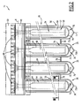
- the figure 4 illustrates a set of heat pipes comprising four heat pipes 54.
- the set of heat pipes comprises, for example, eight or twelve heat pipes 54.
- the set of heat pipes has a flat shape at the end of its manufacture, as shown in FIG. figure 4 .
- the set of heat pipes is arranged in a desired shape when it is arranged in a set of solar collectors, as shown in FIG. figure 2 .
- the tanks 64 of the four heat pipes 54 are delimited by the same first sheet 60 and the same second sheet 62.
- Each reservoir 64 comprises a branch of channels 70 for circulating the heat pipe fluid 58.
- Each reservoir 64 comprises one or more channels 70 for circulation in the hot part 66 of the heat pipe (two in the illustrated example), and several circulation channels 70 in the cold part 68 of the heat pipe (five in the example shown).
- the circulation channels 70 are connected and form with their extensions in the cold part a closed circuit for the heat pipe fluid 58.
- Each of the channels 70 is oriented substantially along the axis I of the corresponding solar collector.
- the term 'substantially' means an angular difference of up to ⁇ 5 °.
- the channels 70 have first parallel straight sections 70A extending in the hot part 66. They are connected at their free end by a first connecting pipe 70B.
- the channels 70 have second parallel rectilinear sections 70C extending in the cold part 68. They are connected at their ends by second connecting ducts 70D.
- the sections 70A and 70C are connected by a beam of convergent sections 70E and then diverging disposed in regions of change of curvature of the heat pipes 54.
- the hot parts 66 of the four heat pipes 54 are disjoint from each other.
- the cold portions 68 of the four heat pipes 54 are fused by three connecting portions 71, each connecting portion 71 being arranged between two adjacent cold portions 68. Each connecting portion 71 extends in a direction of extension of the respective heat pipes 54.
- Each heat pipe 54 has a constriction 72 of its circumferential extent between the hot portion 66 and the cold portion 68, relative to its extent in the running portion of the hot and cold portions 66 and 68.
- the constriction 72 forms a connecting hinge between the hot 66 and the cold part 68.
- the hot part 66 and the cold part 68 have, for example, the same first width L1 perpendicular to the direction of extension of the heat pipes 54.
- the first width L1 is, for example, equal to 80 mm.
- the constriction 72 has, perpendicular to the direction of extension, a second width L2 of lower value than that of the first width L1.
- the second width L2 is, for example, equal to 32 mm.
- the insulation means 56 substantially hermetically surround the absorption layer 52 and are adapted to allow the passage of solar radiation.
- the insulation means 56 are able to thermally isolate the absorption layer 52 and the hot part 66 of the heat pipe with respect to the external climatic conditions of the solar collector 26.
- the insulation means 56 comprise an outer tube 73 and an inner tube 74 disposed inside the outer tube 73.
- the tubes 73, 74 which are substantially cylindrical, have a circular cross section, and are concentric with an axis I.
- the tube outside 73 has a first end 73A and a second end 73B.
- the inner tube 74 has a first end 74A and a second end 74B.
- each tube 73, 74 is closed in the shape of a half-sphere at its first end 73A, 74A, and the tubes 73, 74 are sealed to each other at their second ends 73B, 74B.
- the two tubes 73, 74 are separated by a vacuum 76.
- the tubes 73, 74 are, for example, made of glass.
- the first ends 73A, 74A are oriented opposite the transport conduit 48.
- the second ends 73B, 74B are oriented towards the transport conduit 48.
- the second end 74B of the inner tube is open.
- the isolation means 56 comprise an insulation plug, not shown, inserted into the open end 74B of the inner tube.
- the four sensors 26 are substantially parallel, and the set of sensors comprises a bar 78 connecting the solar collectors 26 between them.
- the connecting bar 78 is disposed substantially perpendicularly to the sensors 26 and in contact with each outer tube 74 on the side of its first end 74A. Specifically, the connecting bar 78 is in contact with each of the sensors 26 in an area between its first end 74A and the middle of its length.
- the term 'substantially' means an angular difference of up to ⁇ 5 °.
- the inner tube 74 has an outer surface 80 facing the outer tube 73, and an inner surface 82, visible on the figure 3 .
- the absorption layer 52 is disposed against the outer surface 78 of the inner tube.
- the hot part 66 of each heat pipe is in the form of a half-cylinder of axis I, as shown in FIG. figure 3 .
- the cross section of the hot portion 66 is shaped like a circular arc of angle A between 180 ° and 220 °.
- each heat pipe and in particular the part of the tank 64 contained in this hot part, is applied against the inner surface 82 of the inner tube.
- the insulating means 56 comprise the only outer tube 73 closed at one of its ends, the absorption layer 52 being disposed inside the outer tube 73.
- the absorption layer 52 is, for example, example, disposed on the surface of the hot portion 66 of the heat pipe.
- the outer tube 73 is hermetically closed around the heat pipe 54 at the other end thereof, the vacuum 76 being formed inside the outer tube 73.
- each heat pipe is in the form of a half-cylinder of axis X arranged between the duct 48 and the insulating sheath 50 being wound around the duct 48, as shown in FIG. figure 2 .
- the axis I of the half-cylinder of the hot part 66 is distinct from the axis X of the half-cylinder of the cold part 68.
- a method of manufacturing the set of heat pipes comprises a hot-rolling assembly step of the first sheet 60 and the second sheet 62 defining between them the tanks 64 of the four heat pipes 54, maintaining the connecting portion 71 between two adjacent heat pipes 54.
- each connecting portion 71 is arranged between two respective cold portions 68.
- the assembly step comprises depositing a specific ink by screen printing the first sheet 60 in a desired pattern for the reservoir 64 of each heat pipe 54, heating the first sheet 60 and the second sheet 62, and the hot rolling of the two sheets 60, 62 to perform a diffusion bonding of the two sheets 60, 62 outside each pattern.
- the heating produced is, for example, a radiative heating.
- the assembly step then comprises a cutting step according to the desired outer contour of the set of heat pipes.
- the cutting is in particular carried out according to the contour of each of the hot parts 66, so that the hot parts 66 of the four heat pipes 54 are disjoint, and according to the contour of each of the constrictions 72.
- the cut is made according to the overall external contour of the four cold parts 68 joined together.
- the cutting is done through a process such as shearing, nibbling, laser cutting, chemical cutting, jet cutting.
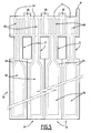
- the assembly step then comprises the injection of compressed air at the level of the patterns occupied by the ink to form each reservoir 64, and the hermetic closure by hot pressing of the ends of each reservoir except for one filling end 84, visible on the figure 5 ..
- the method then comprises a step of evacuating the tanks 64, then filling the tanks 64 with the heat pipe fluid 58.
- the filling of all the tanks 64 from the single filling end 84 is ensured by the presence of three temporary filling ducts 86, each filling duct 86 being arranged between two successive tanks 64 at the level of the cold parts 68.
- the filling end 84 and the temporary filling ducts 86 are removed by cutting, and the heat pipes 54 are hermetically welded at the cut-out locations, so that the tanks 64 are closed individually.
- each temporary filling duct is in the form of an arc of a circle, as shown in FIG. figure 5 or in the form of a rectilinear section between two successive connecting ducts 70.
- the matrix or the punch used for the clinching step are for example in the form of a dovetail.
- the clinching step makes it possible to further improve the resistance to the pressure of the closing of the tanks 64, and the reservoirs 64 are therefore more hermetic to leakage of the heat pipe fluid 58.
- the filling end 84 and the temporary filling ducts 86 are closed during a stamping crushing step, so that the tanks 64 are closed individually.
- the cutting step, or the clinching step, or the crushing step are performed after a step of distributing the mass of the heat pipe fluid 58 between the various reservoirs 64.
- the heat pipe assembly is as shown in FIG. figure 4 .
- Each hot part 66 of heat pipe is then arranged in the form of a half-cylinder, in order to be inserted into the corresponding cylindrical tube of the solar collector 26.
- the electrical energy generation installation is said to be at a low temperature, given the maximum temperature of the hot water production system equal to 150 ° C, which is much lower than that used in other solar thermal power plants, such as that the central cylindro-parabolic sensors, tower plants, parabolic power plants, where the temperature of the coolant circulating in the hot source is above 400 ° C.
- the solar collectors 26 of the heating means 6 capture, during the day, the solar radiation, then transmit to the first coolant 10 the thermal energy associated with solar radiation.
- the solar radiation is absorbed by the absorption layer 52 of each solar sensor, the isolation means 56 allowing the passage of solar radiation.
- the thermal energy associated with the absorption of solar radiation is then transmitted to the heat pipes 54.
- the dissipation of the thermal energy outside the solar collector 26 is limited by the thermal insulation means 56, the vacuum 76 ensuring the thermal insulation and the outer tube the greenhouse effect.
- each heat pipe gradually causes a phase change of the heat pipe fluid 58, its being liquid to its gaseous state.
- the heat pipe fluid in the gaseous state then rises towards the respective cold part 68 of each heat pipe, through the various channels 70 of the tank.
- the reservoir 64 being applied at least locally against the inner tube 74, itself in contact with the absorption layer 52, in the hot part 66 of the heat pipe, the thermal conduction is improved between the absorption layer 52 and the fluid heat pipe 58, so that the losses of heat by blackbody radiation escaping the greenhouse effect, are reduced.
- the heat transported by the heat pipe fluid 58 from the hot part 66 to the cold part 68 is then transmitted to the first heat transfer fluid 10 by thermal conduction between the channels 70 arranged in the cold part and the conduit 48 of the first circuit. This thermal conduction then causes an increase in the temperature of the first coolant 10 and a lowering of the temperature of the heat pipe fluid 58.
- the heat pipe fluid 58 again changes phase progressively from its gaseous state to its liquid state.
- the heat pipe fluid in the liquid state then descends by gravitation from the cold part 68 to the hot part 66, by the angle of inclination, in order to transport again heat energy from the solar radiation.
- the storage means 12 then serve as buffers between the thermal energy produced by the solar collectors 26 of the heating means and that consumed by the thermodynamic machine 6 for generating electricity.
- the heating means 12 thus make it possible to decouple the electricity production from the solar availability.
- the regulation loop 18 makes it possible to adapt the amount of thermal energy supplied by the hot water production system 2 to the thermodynamic machine 6 for producing electricity.
- the operating fluid 40 changes from the liquid state to the gaseous state in the boiler 42.
- the service fluid 40 thus arrives in the gaseous state at the inlet of the turbine 43.
- the service fluid in the gaseous state then expands in the turbine 43 and provides mechanical energy, driving the rotor of the turbine in rotation. This mechanical energy is transmitted to the generator 44, in order to produce electricity.
- the operating fluid 40 is always in the gaseous state, and under a significantly lower pressure.
- the operating fluid 40 then returns to the liquid state in the condenser 45 in contact with the cold source 4. At the outlet of the condenser 45, the operating fluid 40 in the liquid state is then driven by the pump 46 to return to the inlet of the boiler 42 and use again the heat supplied by the hot water production system 2.
- FIG 6 illustrates a second embodiment, for which elements similar to the embodiment described above are identified by identical references.
- the reservoirs 64 of the heat pipes are hydraulically connected to each other so as to form a single reservoir 64 extending over the plurality of heat pipes 54.
- the set of heat pipes comprises third connecting ducts 88.
- Each third connecting conduit 88 connects two adjacent reservoirs 64. More specifically, each third connecting duct 88 is connected between two second adjacent and aligned 70D connecting ducts.
- the set of heat pipes does not comprise the temporary filling ducts of the first embodiment, since it comprises the permanent connecting ducts 88.
- the manufacturing process does not include, after filling tanks, a cutting step, or a clinching step, or a step crushing connecting conduits 88, since the reservoirs 64 of the heat pipes are hydraulically connected to each other and are not closed individually.
- the set of heat pipes according to the invention makes it possible to reduce manufacturing costs, since four heat pipes 54 are produced simultaneously, with a common filling of the tanks 64.
- the realization of the set of solar collectors 26 is facilitated, since the four heat pipes are arranged simultaneously around the transport conduit 48.
- the cold parts 68 of the four heat pipes form a common cold part with an area greater than or equal to the sum of the areas of four conventional heat pipes that are independent of each other, which improves the heat exchange between the solar collectors 26 and the first heat pipe. transport 14.
- the cold parts 68 of the four heat pipes are mechanically connected together, integrally with each other, which improves the mechanical rigidity of the four solar collectors 26 around the transport pipe 48, and reduces the risk of warpage of the solar collectors 26 with respect to the transport duct 48.
- the invention makes it possible to reduce the manufacturing cost of the set of heat pipes and the cost of laying the sensors.
Description
La présente invention est relative à un ensemble de caloducs pour capteurs solaires, du type comprenant une pluralité de caloducs, chaque caloduc étant propre à être agencé dans un capteur solaire respectif, et comprenant un fluide de caloduc, une première feuille et une deuxième feuille localement fusionnées entre elles et délimitant un réservoir, le réservoir contenant le fluide de caloduc, s'étendant sur une partie chaude d'évaporation du fluide de caloduc et une partie froide de condensation du fluide de caloduc, et étant formé par un interstice entre les deux feuilles un tel ensemble est connu du document
L'invention concerne également un ensemble de capteurs solaires du type comprenant une pluralité de capteurs solaires, chaque capteur comprenant :
- un tube extérieur de section circulaire, ayant deux extrémités et étant fermé en une première de ses extrémités,
- une couche d'absorption du rayonnement solaire disposée à l'intérieur du tube extérieur,
- un caloduc respectif d'un ensemble de caloducs,
- an outer tube of circular section, having two ends and being closed at a first end,
- a solar radiation absorption layer disposed inside the outer tube,
- a respective heat pipe of a set of heat pipes,
L'invention concerne également un système de production d'eau chaude comprenant un tel ensemble de capteurs solaires, et une installation de génération d'énergie électrique à partir d'énergie solaire comprenant un tel système de production d'eau chaude.The invention also relates to a hot water production system comprising such a set of solar collectors, and an installation for generating electrical energy from solar energy comprising such a hot water production system.
L'invention concerne également un procédé de fabrication d'un ensemble de caloducs pour capteurs solaires.The invention also relates to a method of manufacturing a set of heat pipes for solar collectors.
On connaît un ensemble de caloducs pour capteurs solaires du type précité. Lors de la fabrication de tels caloducs, deux feuilles sont fusionnées entre elles en délimitant les réservoirs des caloducs. Les deux feuilles sont alors découpées selon le contour extérieur respectif de chacun des caloducs. Chaque réservoir respectif est ensuite rempli avec un fluide de caloduc.There is known a set of heat pipes for solar collectors of the aforementioned type. During the manufacture of such heat pipes, two sheets are fused together by delimiting the heat pipe tanks. The two sheets are then cut according to the respective outer contour of each of the heat pipes. Each respective reservoir is then filled with a heat pipe fluid.
La partie chaude des caloducs est alors agencée dans un capteur solaire respectif, et la partie froide de chaque caloduc respectif est connectée à un conduit de transport d'un fluide caloporteur destiné à être chauffé.The hot part of the heat pipes is then arranged in a respective solar collector, and the cold part of each respective heat pipe is connected to a conduit for transporting a coolant intended to be heated.
Toutefois, les caloducs présentent un coût de fabrication élevé. En outre, l'ensemble de caloducs présente un risque de gauchissement avec le conduit de transport du fluide caloporteur, lorsque les parties froides des caloducs sont connectées à ce conduit, et que celui-ci s'allonge sous l'effet de la température.However, the heat pipes have a high manufacturing cost. In addition, the set of heat pipes presents a risk of warping with the heat transfer fluid transport duct, when the cold parts of the heat pipes are connected to this duct, and that it elongates under the effect of temperature.
Un but de l'invention est de réduire le coût de fabrication de l'ensemble de caloducs.An object of the invention is to reduce the manufacturing cost of the set of heat pipes.
A cet effet, l'invention a pour objet un ensemble de caloducs du type précité, caractérisé en ce que les réservoirs d'au moins deux caloducs sont délimités par une même première feuille et une même deuxième feuille, et en ce que les parties froides desdits au moins deux caloducs sont partiellement fusionnées entre elles deux à deux, et les parties chaudes desdits au moins deux caloducs sont disjointes.For this purpose, the invention relates to a set of heat pipes of the aforementioned type, characterized in that the reservoirs of at least two heat pipes are delimited by the same first sheet and the same second sheet, and in that the cold parts said at least two heat pipes are partially fused together in pairs, and the hot portions of said at least two heat pipes are disjointed.
Suivant d'autres modes de réalisation, l'ensemble de caloducs comprend une ou plusieurs des caractéristiques suivantes, prises isolément ou suivant toutes les combinaisons techniquement possibles :
- les réservoirs des caloducs sont reliés hydrauliquement entre eux de manière à former un unique réservoir s'étendant sur la pluralité de caloducs ;
- les feuilles sont métalliques, de préférence en aluminium.
- the heat pipe tanks are hydraulically connected to each other so as to form a single tank extending over the plurality of heat pipes;
- the sheets are metallic, preferably aluminum.
L'invention a également pour objet un ensemble de capteurs solaires du type précité, caractérisé en ce que l'ensemble de caloducs est tel que défini ci-dessus.The invention also relates to a set of solar collectors of the aforementioned type, characterized in that the set of heat pipes is as defined above.
Suivant d'autres modes de réalisation, l'ensemble de capteurs solaires comprend une ou plusieurs des caractéristiques suivantes, prises isolément ou suivant toutes les combinaisons techniquement possibles :
- chaque capteur solaire comprend en outre un tube intérieur de section circulaire, disposé à l'intérieur du tube extérieur, chaque tube ayant deux extrémités et étant fermé en une première de ses extrémités, et les tubes étant scellés l'un à l'autre, en la seconde de leurs extrémités, les tubes étant séparés par du vide ;
- le tube intérieur de chaque capteur comporte une surface extérieure orientée vers le tube extérieur dudit capteur, et une surface intérieure, la couche d'absorption dudit capteur est disposée contre ladite surface extérieure, et pour la partie chaude du caloduc dudit capteur, le réservoir est appliqué au moins localement contre ladite surface intérieure ;
- la partie chaude de chaque caloduc est en forme d'un demi-cylindre ;
- la partie froide de chaque caloduc est propre à être disposée au contact d'un conduit cylindrique, et ladite partie froide est en forme d'un demi-cylindre ;
- l'axe du demi-cylindre de la partie chaude de chaque caloduc est distinct de l'axe du demi-cylindre de la partie froide du caloduc correspondant, et le caloduc comporte un rétrécissement de son étendue circonférentielle et/ou longitudinale par rapport à son étendue dans la partie courante des parties chaude et froide, entre la partie chaude et la partie froide formant une charnière de liaison ;
- les capteurs sont sensiblement parallèles les uns des autres, et l'ensemble comporte au moins une barre de liaison des capteurs solaires entre eux, ladite barre étant disposée sensiblement perpendiculairement aux capteurs et au contact de chaque tube extérieur du côté de sa première extrémité.
- each solar collector further comprises an inner tube of circular section, disposed inside the outer tube, each tube having two ends and being closed at a first end, and the tubes being sealed to one another, in the second of their ends, the tubes being separated by vacuum;
- the inner tube of each sensor has an outer surface facing the outer tube of said sensor, and an inner surface, the absorption layer of said sensor is disposed against said outer surface, and for the hot part of the heat pipe of said sensor, the reservoir is applied at least locally against said inner surface;
- the hot part of each heat pipe is in the shape of a half-cylinder;
- the cold part of each heat pipe is adapted to be disposed in contact with a cylindrical duct, and said cold part is in the form of a half-cylinder;
- the axis of the half-cylinder of the hot part of each heat pipe is distinct from the axis of the half-cylinder of the cold part of the corresponding heat pipe, and the heat pipe comprises a narrowing of its circumferential and / or longitudinal extent with respect to its extending in the current part of the hot and cold parts, between the hot part and the cold part forming a connecting hinge;
- the sensors are substantially parallel to one another, and the assembly comprises at least one connecting bar of the solar collectors between them, said bar being disposed substantially perpendicular to the sensors and in contact with each outer tube on the side of its first end.
L'invention a également pour objet un système de production d'eau chaude à partir d'énergie solaire comprenant :
- un ensemble de capteurs solaires propres à chauffer un fluide caloporteur à partir d'énergie solaire, et
- un circuit de transport du fluide caloporteur entre les capteurs solaires et un distributeur d'eau chaude,
- a set of solar collectors adapted to heat a heat transfer fluid from solar energy, and
- a heat transfer fluid transport circuit between the solar collectors and a hot water dispenser,
L'invention a également pour objet une installation de génération d'énergie électrique à partir des énergies solaires comprenant :
- un système de production d'eau chaude,
- une source froide, et
- une machine thermodynamique de production d'électricité, utilisant l'eau chaude produite par ledit système et la source froide,
- a hot water production system,
- a cold source, and
- a thermodynamic machine for producing electricity, using the hot water produced by said system and the cold source,
L'invention a également pour objet un procédé de fabrication d'un ensemble de caloducs pour capteurs solaires comprenant une pluralité de caloducs, le procédé comportant :
- l'assemblage d'une première feuille et d'une deuxième feuille délimitant entre elles les réservoirs d'au moins deux caloducs, en maintenant une portion de liaison entre deux caloducs adjacents parmi lesdits au moins deux caloducs, et
- le remplissage des réservoirs avec un fluide de caloduc.
- assembling a first sheet and a second sheet delimiting between them the reservoirs of at least two heat pipes, maintaining a connecting portion between two adjacent heat pipes of said at least two heat pipes, and
- filling the tanks with a heat pipe fluid.
Suivant un autre mode de réalisation, le procédé comprend la caractéristique suivante :
- l'étape d'assemblage comporte :
- ▪ le dépôt d'une encre spécifique par sérigraphie de la première feuille selon un motif désiré pour un réservoir de chaque caloduc,
- ▪ le chauffage de la première feuille et de la seconde feuille,
- ▪ le laminage à chaud des deux feuilles pour réaliser une soudure par diffusion des deux feuilles en dehors de chaque motif,
- ▪ l'injection d'air comprimé au niveau des zones occupées par les motifs d'encre, pour former chaque réservoir, et
- ▪ la fermeture hermétique, par pressage à chaud, des extrémités de chaque réservoir à l'exception d'une extrémité de remplissage.
- the assembly step comprises:
- Depositing a specific ink by serigraphy of the first sheet in a desired pattern for a reservoir of each heat pipe,
- ▪ heating the first sheet and the second sheet,
- ▪ hot rolling of the two sheets to achieve diffusion bonding of the two sheets outside each pattern,
- ▪ the injection of compressed air at the zones occupied by the ink patterns, to form each reservoir, and
- ▪ sealing, by hot pressing, the ends of each tank except for a filling end.
Ces caractéristiques et avantages de l'invention apparaîtront à la lecture de la description qui va suivre, donnée uniquement à titre d'exemple, et faite en référence aux dessins annexés, sur lesquels :
- la
figure 1 est une représentation schématique d'une installation de génération d'énergie électrique selon l'invention ; - la
figure 2 est une vue schématique de dessus d'un ensemble de quatre capteurs solaires selon l'invention, - la
figure 3 est une vue en coupe selon le plan III de lafigure 2 , - la
figure 4 est une vue schématique de dessus d'un ensemble de caloducs de lafigure 2 , selon un premier mode de réalisation de l'invention, - la
figure 5 est une vue schématique d'une étape de fabrication de l'ensemble de caloducs de lafigure 4 , - la
figure 6 est une vue analogue à celle de lafigure 4 selon un deuxième mode de réalisation de l'invention.
- the
figure 1 is a schematic representation of an electrical energy generation installation according to the invention; - the
figure 2 is a diagrammatic view from above of a set of four solar collectors according to the invention, - the
figure 3 is a sectional view according to plan III of thefigure 2 , - the
figure 4 is a schematic view from above of a set of heat pipes of thefigure 2 according to a first embodiment of the invention, - the
figure 5 is a schematic view of a step of manufacturing the set of heat pipes of thefigure 4 , - the
figure 6 is a view similar to that of thefigure 4 according to a second embodiment of the invention.
Sur la
Le système de production d'eau chaude 2 comprend des moyens de chauffage 8 par énergie solaire d'un premier fluide caloporteur 10, tel que de l'eau, des moyens 12 de stockage de l'énergie thermique et un premier circuit fermé 14 de transport du premier fluide caloporteur 10. Le premier circuit 14 relie les moyens de chauffage 8, les moyens de stockage 12 et la machine thermodynamique 6 de production d'électricité.The hot
Le système de production d'eau chaude 2 comprend une bâche de stockage 16 pour délester le premier circuit 14, et une boucle de régulation 18 comportant un mélangeur 20 et une première pompe 22. L'installation comporte des moyens 24 de commande à distance de la boucle 18.The hot
Les moyens de chauffage 8 comportent une pluralité de capteurs solaires 26 décrits plus en détail par la suite en référence aux
Le premier circuit 14 comporte une pluralité de vannes 28, le mélangeur 20, la première pompe 22 et une deuxième pompe 30. Le premier circuit 14 comporte un échangeur 31, en forme de serpentin, destiné à transmettre la chaleur transportée par le fluide caloporteur 10 à la machine thermodynamique 6.The
En variante, le système de production d'eau chaude 2 comprend un distributeur d'eau chaude, et n'est pas relié à une machine thermodynamique de production d'électricité. Le circuit 14 de transport du fluide caloporteur 10 relie les capteurs solaires 26 au distributeur d'eau chaude. Le distributeur comprend l'échangeur 31 destiné à transmettre la chaleur transportée par le fluide caloporteur 10.Alternatively, the hot
La source froide 4 comprend un deuxième circuit 32 de transport d'un deuxième fluide caloporteur 34, tel que de l'eau. La circulation est assurée par une pompe 36.The cold source 4 comprises a
La machine thermodynamique 6 comprend un troisième circuit 38 de transport d'un fluide de service 40, une chaudière 42, une turbine 43 couplée à une génératrice d'électricité 44 et un condenseur 45. La circulation du fluide de service 40 dans le troisième circuit 38 est assurée par une pompe 46.The thermodynamic machine 6 comprises a
La
Chaque capteur solaire 26 comprend une couche 52 d'absorption d'un rayonnement solaire, un caloduc 54, et des moyens d'isolation thermique 56. La couche d'absorption 52 est, par exemple, réalisée en nitrite d'aluminium pulvérisé. Chaque capteur solaire 26 s'étend selon un axe I incliné par rapport au plan horizontal. L'axe I forme avec le plan horizontal un angle d'inclinaison supérieur à 5 °, de préférence supérieur à 30 °.Each
Sur la
Le réservoir 64 s'étend sur une partie chaude 66 d'évaporation du fluide de caloduc et une partie froide 68 de condensation du fluide de caloduc, comme représenté sur la
La
L'ensemble des caloducs présente une forme plane à l'issue de sa fabrication, comme représenté sur la
Les réservoirs 64 des quatre caloducs 54 sont délimités par la même première feuille 60 et la même deuxième feuille 62.The
Chaque réservoir 64 comporte une ramification de canaux 70 de circulation du fluide de caloduc 58. Chaque réservoir 64 comporte un ou plusieurs canaux 70 de circulation dans la partie chaude 66 du caloduc (deux dans l'exemple illustré), et plusieurs canaux 70 de circulation dans la partie froide 68 du caloduc (cinq dans l'exemple illustré). Les canaux de circulation 70 sont reliés et forment avec leurs prolongements dans la partie froide un circuit fermé pour le fluide de caloduc 58. Chacun des canaux 70 est orienté sensiblement selon l'axe I du capteur solaire correspondant. Le terme 'sensiblement' s'entend par un écart angulaire allant jusqu'à ±5°.Each
Les canaux 70 présentent des premiers tronçons rectilignes 70A parallèles s'étendant dans la partie chaude 66. Ils sont reliés à leur extrémité libre par un premier conduit de liaison 70B. Les canaux 70 présentent des deuxièmes tronçons rectilignes 70C parallèles s'étendant dans la partie froide 68. Ils sont reliés à leurs extrémités par des deuxièmes conduits de liaison 70D. Les tronçons 70A et 70C sont reliés par un faisceau de tronçons convergents 70E puis divergents disposés dans des régions de changement de courbure des caloducs 54.The
Les parties chaudes 66 des quatre caloducs 54 sont disjointes les unes des autres.The
Les parties froides 68 des quatre caloducs 54 sont fusionnées par trois portions de liaison 71, chaque portion de liaison 71 étant agencée entre deux parties froides 68 adjacentes. Chaque portion de liaison 71 s'étend selon une direction d'extension des caloducs 54 respectifs.The
Chaque caloduc 54 comporte un rétrécissement 72 de son étendue circonférentielle entre la partie chaude 66 et la partie froide 68, par rapport à son étendue dans la partie courante des parties chaude 66 et froide 68. Le rétrécissement 72 forme une charnière de liaison entre la partie chaude 66 et la partie froide 68.Each
La partie chaude 66 et la partie froide 68 présentent, par exemple, une même première largeur L1 perpendiculairement à la direction d'extension des caloducs 54. La première largeur L1 est, par exemple, égale à 80 mm. Le rétrécissement 72 présente, perpendiculairement à la direction d'extension, une deuxième largeur L2 de valeur inférieure à celle de la première largeur L1. La deuxième largeur L2 est, par exemple, égale à 32 mm.The
Les moyens d'isolation 56, visibles sur la
Les moyens d'isolation 56 comprennent un tube extérieur 73 et un tube intérieur 74 disposé à l'intérieur du tube extérieur 73. Les tubes 73, 74, sensiblement cylindriques, présentent une section circulaire, et sont concentriques d'axe I. Le tube extérieur 73 a une première extrémité 73A et une seconde extrémité 73B. Le tube intérieur 74 a une première extrémité 74A et une seconde extrémité 74B.The insulation means 56 comprise an
Comme représenté sur la
Les premières extrémités 73A, 74A sont orientées à l'opposé du conduit de transport 48.Les secondes extrémités 73B, 74B sont orientées vers le conduit de transport 48. La seconde extrémité 74B du tube intérieur est ouverte. Les moyens d'isolation 56 comportent un bouchon d'isolation, non représenté, inséré dans l'extrémité ouverte 74B du tube intérieur.The first ends 73A, 74A are oriented opposite the
Les quatre capteurs 26 sont sensiblement parallèles, et l'ensemble de capteurs comporte une barre 78 de liaison des capteurs solaires 26 entre eux. La barre de liaison 78 est disposée sensiblement perpendiculairement aux capteurs 26 et au contact de chaque tube extérieur 74 du côté de sa première extrémité 74A. Plus précisément, la barre de liaison 78 est en contact avec chacun des capteurs 26 dans une zone comprise entre sa première extrémité 74A et le milieu de sa longueur. Le terme 'sensiblement' s'entend par un écart angulaire allant jusqu'à ±5°.The four
Le tube intérieur 74 comporte une surface extérieure 80 orientée vers le tube extérieur 73, et une surface intérieure 82, visibles sur la
La partie chaude 66 de chaque caloduc est en forme d'un demi-cylindre d'axe I, comme représenté sur la
La partie chaude 66 de chaque caloduc, et notamment la partie du réservoir 64 contenue dans cette partie chaude, est appliquée contre la surface intérieure 82 du tube intérieur.The
En variante, les moyens d'isolation 56 comprennent le seul tube extérieur 73 fermé en l'une de ses extrémités, la couche d'absorption 52 étant disposée à l'intérieur du tube extérieur 73. La couche d'absorption 52 est, par exemple, disposée sur la surface de la partie chaude 66 du caloduc. Le tube extérieur 73 est fermé de manière hermétique autour du caloduc 54 en l'autre de ses extrémités, le vide 76 étant formé à l'intérieur du tube extérieur 73.In a variant, the insulating
La partie froide 68 de chaque caloduc est en forme d'un demi-cylindre d'axe X agencé entre le conduit 48 et la gaine isolante 50 en étant enroulé autour du conduit 48, comme représenté sur la
L'axe I du demi-cylindre de la partie chaude 66 est distinct de l'axe X du demi-cylindre de la partie froide 68.The axis I of the half-cylinder of the
Un procédé de fabrication de l'ensemble de caloducs, visible sur les
L'étape d'assemblage comporte le dépôt d'une encre spécifique par sérigraphie de la première feuille 60 selon un motif désiré pour le réservoir 64 de chaque caloduc 54, le chauffage de la première feuille 60 et de la seconde feuille 62, et le laminage à chaud des deux feuilles 60, 62 pour réaliser une soudure par diffusion des deux feuilles 60, 62 en dehors de chaque motif. Le chauffage réalisé est, par exemple, un chauffage radiatif.The assembly step comprises depositing a specific ink by screen printing the
L'étape d'assemblage comporte alors une étape de découpe selon le contour extérieur désiré de l'ensemble de caloducs. La découpe est notamment effectuée selon le contour de chacune des parties chaudes 66, de sorte que les parties chaudes 66 des quatre caloducs 54 sont disjointes, et selon le contour de chacun des rétrécissements 72. La découpe est réalisée selon le contour extérieur global des quatre parties froides 68 réunies. La découpe est réalisée grâce à un procédé tel qu'un cisaillage, un grignotage, une découpe laser, une découpe chimique, une découpe par jet d'eau.The assembly step then comprises a cutting step according to the desired outer contour of the set of heat pipes. The cutting is in particular carried out according to the contour of each of the
L'étape d'assemblage comporte ensuite l'injection d'air comprimé au niveau des motifs occupés par l'encre pour former chaque réservoir 64, et la fermeture hermétique par pressage à chaud des extrémités de chaque réservoir à l'exception d'une extrémité de remplissage 84, visible sur la
Le procédé comporte ensuite une étape de mise sous vide des réservoirs 64, puis de remplissage des réservoirs 64 avec le fluide de caloduc 58. Le remplissage de tous les réservoirs 64 à partir de la seule extrémité de remplissage 84 est assuré de par la présence de trois conduits temporaires de remplissage 86, chaque conduit de remplissage 86 étant agencé entre deux réservoirs 64 successifs au niveau des parties froides 68.The method then comprises a step of evacuating the
Après le remplissage des réservoirs 64, l'extrémité de remplissage 84 et les conduits temporaires de remplissage 86 sont éliminés par découpe, et les caloducs 54 sont soudés hermétiquement aux endroits découpés, de sorte que les réservoirs 64 sont fermés individuellement.After the
En variante, après le remplissage des réservoirs 64, l'extrémité de remplissage 84 et les conduits temporaires de remplissage 86 sont obturés par clinchage, c'est-à-dire par emboutissage de ladite extrémité et desdits conduits temporaires entre un poinçon et une matrice, de sorte que les réservoirs 64 sont fermés individuellement. Selon cette variante, chaque conduit temporaire de remplissage est en forme d'un arc de cercle, comme représenté sur la
En variante encore, après le remplissage des réservoirs 64, l'extrémité de remplissage 84 et les conduits temporaires de remplissage 86 sont obturés au cours d'une étape d'écrasement par emboutissage, de sorte que les réservoirs 64 sont fermés individuellement.In another variant, after the filling of the
En complément, l'étape de découpe, ou l'étape de clinchage, ou encore l'étape d'écrasement sont réalisées après une étape de répartition de la masse du fluide de caloduc 58 entre les différents réservoirs 64.In addition, the cutting step, or the clinching step, or the crushing step are performed after a step of distributing the mass of the
A l'issue du procédé de fabrication, l'ensemble de caloducs est tel que représenté sur la
Chaque partie chaude 66 de caloduc est alors agencée en forme de demi-cylindre, afin d'être insérée dans le tube cylindrique correspondant du capteur solaire 26.Each
Le fonctionnement de l'installation de génération d'énergie électrique, et en particulier des capteurs solaires, va maintenant être décrit.The operation of the electrical energy generation installation, and in particular solar collectors, will now be described.
L'installation de génération d'énergie électrique est dite à basse température, compte tenu de la température maximale du système de production d'eau chaude égale à 150°C qui est nettement inférieure à celle utilisée dans d'autres centrales solaires thermiques, telles que les centrales à capteurs cylindro-paraboliques, les centrales à tours, les centrales à capteurs paraboliques, où la température du fluide caloporteur circulant dans la source chaude est supérieure à 400 °C.The electrical energy generation installation is said to be at a low temperature, given the maximum temperature of the hot water production system equal to 150 ° C, which is much lower than that used in other solar thermal power plants, such as that the central cylindro-parabolic sensors, tower plants, parabolic power plants, where the temperature of the coolant circulating in the hot source is above 400 ° C.
Les capteurs solaires 26 des moyens de chauffage 6 captent, durant la journée, le rayonnement solaire, puis transmettent au premier fluide caloporteur 10 l'énergie thermique associée au rayonnement solaire.The
Plus précisément, le rayonnement solaire est absorbé par la couche d'absorption 52 de chaque capteur solaire, les moyens d'isolation 56 permettant le passage du rayonnement solaire. L'énergie thermique associée à l'absorption du rayonnement solaire est alors transmise aux caloducs 54. La dissipation de l'énergie thermique en dehors du capteur solaire 26 est limitée de par les moyens d'isolation thermique 56, le vide 76 assurant l'isolation thermique et le tube extérieur l'effet de serre.More specifically, the solar radiation is absorbed by the
L'énergie thermique transmise à la partie chaude 66 de chaque caloduc entraîne progressivement un changement de phase du fluide de caloduc 58, de son étant liquide à son état gazeux. Le fluide de caloduc à l'état gazeux s'élève alors en direction de la partie froide 68 respective de chaque caloduc, à travers les différents canaux 70 du réservoir. Le réservoir 64 étant appliqué au moins localement contre le tube intérieur 74, lui-même en contact avec la couche d'absorption 52, dans la partie chaude 66 du caloduc, la conduction thermique est améliorée entre la couche d'absorption 52 et le fluide du caloduc 58, de sorte que les pertes de chaleur par rayonnement de corps noir échappant à l'effet de serre, sont réduites.The heat energy transmitted to the
La chaleur transportée par le fluide de caloduc 58 de la partie chaude 66 vers la partie froide 68 est alors transmise au premier fluide caloporteur 10 par conduction thermique entre les canaux 70 disposés dans la partie froide et le conduit 48 du premier circuit. Cette conduction thermique entraîne alors une élévation de la température du premier fluide caloporteur 10 et un abaissement de la température du fluide de caloduc 58.The heat transported by the
Suite à l'abaissement de la température du fluide de caloduc 58, le fluide de caloduc 58 change à nouveau progressivement de phase, de son état gazeux à son état liquide. Le fluide de caloduc à l'état liquide redescend alors par gravitation de la partie froide 68 vers la partie chaude 66, de par l'angle d'inclinaison, afin de transporter à nouveau de l'énergie thermique issue du rayonnement solaire.Following the lowering of the temperature of the
Les moyens de stockage 12 servent alors de tampons entre l'énergie thermique produite par les capteurs solaires 26 des moyens de chauffage et celle consommée par la machine thermodynamique 6 de production d'électricité. Les moyens de chauffage 12 permettent donc de découpler la production d'électricité de la disponibilité solaire.The storage means 12 then serve as buffers between the thermal energy produced by the
Plusieurs modes de fonctionnement sont envisageables au niveau du système de production d'eau chaude 2, à l'aide des vannes 28, du mélangeur 20 et des pompes 22, 30 : le stockage seul d'énergie thermique, la production directe d'énergie thermique, le stockage et la production d'énergie thermique, le déstockage d'énergie thermique et la production directe d'énergie thermique, et le déstockage seul d'énergie thermique.Several operating modes can be envisaged at the level of the hot
La boucle de régulation 18 permet d'adapter la quantité d'énergie thermique fournie par le système de production d'eau chaude 2 à la machine thermodynamique 6 de production d'électricité.The
De par la chaleur apportée par le système de production d'eau chaude 2, le fluide de service 40 passe de l'état liquide à l'état gazeux dans la chaudière 42. Le fluide de service 40 arrive ainsi à l'état gazeux à l'entrée de la turbine 43. Le fluide de service à l'état gazeux se détend alors dans la turbine 43 et fournit de l'énergie mécanique, en entraînant le rotor de la turbine en rotation. Cette énergie mécanique est transmise à la génératrice 44, afin de produire de l'électricité. En sortie de la turbine 43, le fluide de service 40 est toujours à l'état gazeux, et sous une pression nettement inférieure.Due to the heat provided by the hot
Le fluide de service 40 repasse alors à l'état liquide dans le condenseur 45 au contact de la source froide 4. En sortie du condenseur 45, le fluide de service 40 à l'état liquide est alors entraîné par la pompe 46 pour retourner à l'entrée de la chaudière 42 et exploiter de nouveau la chaleur fournie par le système de production d'eau chaude 2.The operating
La
Selon ce deuxième mode de réalisation, les réservoirs 64 des caloducs sont reliés hydrauliquement entre eux de manière à former un unique réservoir 64 s'étendant sur la pluralité de caloducs 54. L'ensemble de caloducs comprend des troisièmes conduits de liaison 88. Chaque troisième conduit de liaison 88 relie deux réservoirs 64 adjacents. Plus précisément, chaque troisième conduit de liaison 88 est connecté entre deux deuxièmes conduits de liaison 70D adjacents et alignés.According to this second embodiment, the
Le procédé de fabrication de ce deuxième mode de réalisation est identique à celui du premier mode de réalisation, et n'est donc pas décrit à nouveau.The manufacturing method of this second embodiment is identical to that of the first embodiment, and is therefore not described again.
Le fonctionnement de ce deuxième mode de réalisation est identique à celui du premier mode de réalisation, et n'est donc pas décrit à nouveau.The operation of this second embodiment is identical to that of the first embodiment, and is therefore not described again.
L'homme du métier comprendra que, selon ce deuxième mode de réalisation, l'ensemble de caloducs ne comporte pas les conduits temporaires de remplissage du premier mode de réalisation, puisqu'il comprend les conduits permanents de liaison 88. L'homme du métier comprendra également que le procédé de fabrication ne comporte pas, après le remplissage des réservoirs, une étape de découpe, ou encore une étape de clinchage, ou encore une étape d'écrasement des conduits de liaison 88, puisque les réservoirs 64 des caloducs sont reliés hydrauliquement entre eux et ne sont pas fermés individuellement.Those skilled in the art will understand that, according to this second embodiment, the set of heat pipes does not comprise the temporary filling ducts of the first embodiment, since it comprises the permanent connecting
Ainsi, l'ensemble de caloducs selon l'invention permet de réduire les coûts de fabrication, puisque quatre caloducs 54 sont réalisés simultanément, avec un remplissage commun des réservoirs 64. La réalisation de l'ensemble de capteurs solaires 26 en est facilitée, puisque les quatre caloducs sont agencés simultanément autour du conduit de transport 48.Thus, the set of heat pipes according to the invention makes it possible to reduce manufacturing costs, since four
Les parties froides 68 des quatre caloducs forment une partie froide commune, d'aire supérieure ou égale à la somme des aires de quatre caloducs classiques indépendants les uns des autres, ce qui améliore les échanges thermiques entre les capteurs solaires 26 et le premier circuit de transport 14.The
Les parties froides 68 des quatre caloducs sont reliées mécaniquement entre elles, solidairement les unes des autres, ce qui améliore la rigidité mécanique des quatre capteurs solaires 26 autour du conduit de transport 48, et réduit les risques de gauchissement des capteurs solaires 26 par rapport au conduit de transport 48.The
On conçoit ainsi que l'invention permet de réduire le coût de fabrication de l'ensemble de caloducs et le coût de pose des capteurs.It is thus conceived that the invention makes it possible to reduce the manufacturing cost of the set of heat pipes and the cost of laying the sensors.
Claims (15)
- A set of heat pipes for solar collectors, of the type comprising a plurality of heat pipes (54), each heat pipe (54) being suitable for being laid out in a respective solar collector (26), and comprising a heat pipe fluid (58), a first sheet (60) and a second sheet (62) merged locally with each other and delimiting a reservoir (64), the reservoir (64) containing the heat pipe fluid (58), extending over a hot part (66) for evaporating the heat pipe fluid (58) and a cold part (68) for condensing the heat pipe fluid (58), and being formed by an interstice (69) between the two sheets (60, 62), the reservoirs (64) of at least two heat pipes (54) being delimited by a same first sheet (60) and a same second sheet (62),
characterized in that the cold parts (68) of said at least two heat pipes (54) are partly merged with each other in pairs, and in that the hot parts (66) of said at least two heat pipes (54) are separate. - The set according to claim 1, characterized in that the reservoirs (64) of the heat pipes (54) are hydraulically interlinked to form a single reservoir extending over the plurality of the heat pipes (54).
- The set according to claim 1 or 2, characterized in that the sheets (60, 62) are metal sheets, preferably made of aluminium.
- A set of solar collectors, of the type comprising a plurality of solar collectors (26), each collector (26) comprising:- an outer tube (73) of circular cross-section, having two ends (73A, 73B) and being closed at a first (73A) of its ends,- a solar radiation absorption layer (52) arranged inside the outer tube (73),- a respective heat pipe (54) of a set of heat pipes,each outer tube (73) being hermetically closed around the respective heat pipe (54) at the second (73B) of its ends (73A, 73B), a vacuum (76) being formed inside said outer tube (73),
characterized in that the set of heat pipes is in accordance with any one of the preceding claims. - The set of solar collectors according to claim 4, characterized in that each solar collector (26) additionally comprises an inner tube (74) of circular cross-section, arranged inside the outer tube (73), each tube (73, 74) having two ends (73A, 73B, 74A, 74B) and being closed at a first (73A, 74A) of its ends, and the tubes (73, 74) being sealed one to the other at the second (73B, 74B) of their ends, the tubes (73, 74) being separated by the vacuum (76).
- The set of solar collectors according to claim 5, characterized in that the inner tube (74) of each collector includes an outer surface (80) oriented towards the outer tube (73) of said collector (26), and an inner surface (82), in that the absorption layer (52) of said collector (26) is arranged against said outer surface (80), and in that, for the hot part (66) of the heat pipe (54) of said collector (26), the reservoir (64) is applied at least locally against said inner surface (82).
- The set of solar collectors according to any one of claims 4 to 6, characterized in that the hot part (66) of each heat pipe (54) is in the shape of a half-cylinder.
- The set of solar collectors according to any one of claims 4 to 7, characterized in that the cold part (68) of each heat pipe (54) is suitable for being arranged in contact with a cylindrical pipe (48), and in that said cold part (68) is in the shape of a half-cylinder.
- The set of solar collectors according to claims 7 and 8 taken together, characterized in that the axis (I) of the half-cylinder of the hot part (66) of each heat pipe (54) is different from the axis (X) of the half-cylinder of the cold part (68) of the corresponding heat pipe (54), and in that the heat pipe (54) includes a narrowing (72) of its circumferential and/or longitudinal extent with respect to its extent in the regular part of the hot (66) and cold (68) parts, between the hot part (66) and the cold part (68) forming a connecting joint.
- The set of solar collectors according to any one of claims 4 to 9, characterized in that the collectors (26) are substantially parallel with one another, and in that the set includes at least one connecting bar (78) interconnecting the solar collectors (26), said bar (78) being arranged substantially perpendicularly to the collectors (26) and in contact with each outer tube (73) near its first end (73A).
- A system (2) for producing hot water from solar energy comprising:- a set of solar collectors (26) suitable for heating a heat transfer fluid (10) from solar energy, and- a circuit (14) for transporting the heat transfer fluid (10) between the solar collectors (26) and a hot water distributor,characterized in that the set of solar collectors is in accordance with any one of claims 4 to 10.
- A plant for generating electrical energy from solar energy comprising:- a hot water production system (2),- a heat sink (4), and- an electricity-producing thermodynamic machine (6), using the hot water produced by said system (2) and the heat sink (4),characterized in that the hot water production system (2) is in accordance with claim 11.
- A method for manufacturing a set of heat pipes for solar collectors (26), comprising a plurality of heat pipes (54), the method including the steps of:- assembling a first sheet (60) and a second sheet (62) delimiting between them the reservoirs (64) of at least two heat pipes (54), while maintaining a connecting portion (71) between two adjacent heat pipes (54) among said at least two heat pipes (54),- cutting the set of heat pipes according to the external outline of each of the hot parts (66), such that the hot parts (66) of the heat pipes are separate, and- filling the reservoirs (64) with a heat pipe fluid (58).
- The method according to claim 13, characterized in that the reservoirs are filled from only one filling end (84).
- The method according to claim 13 or 14, the set of heat pipes including at least one temporary filling pipe (86), each temporary filling pipe (86) being laid out between two successive reservoirs (64) at the cold parts (68),
characterized in that the method includes, after the reservoirs (64) are filled, the step of cutting the temporary filling pipes (86) and hermetically welding the heat pipes (54) at the cut locations, such that the reservoirs (64) are closed individually.
Priority Applications (3)
| Application Number | Priority Date | Filing Date | Title |
|---|---|---|---|
| SI201030975T SI2396606T1 (en) | 2009-02-12 | 2010-01-21 | Heat pipe assembly for solar collectors |
| PL10707328T PL2396606T3 (en) | 2009-02-12 | 2010-01-21 | Heat pipe assembly for solar collectors |
| HRP20150687TT HRP20150687T1 (en) | 2009-02-12 | 2015-06-29 | Heat pipe assembly for solar collectors |
Applications Claiming Priority (2)
| Application Number | Priority Date | Filing Date | Title |
|---|---|---|---|
| FR0950885A FR2942030B1 (en) | 2009-02-12 | 2009-02-12 | SET OF CALODUCKS FOR SOLAR SENSORS |
| PCT/FR2010/050088 WO2010092269A2 (en) | 2009-02-12 | 2010-01-21 | Heat pipe assembly for solar collectors |
Publications (2)
| Publication Number | Publication Date |
|---|---|
| EP2396606A2 EP2396606A2 (en) | 2011-12-21 |
| EP2396606B1 true EP2396606B1 (en) | 2015-04-08 |
Family
ID=41082591
Family Applications (1)
| Application Number | Title | Priority Date | Filing Date |
|---|---|---|---|
| EP10707328.0A Active EP2396606B1 (en) | 2009-02-12 | 2010-01-21 | Heat pipe assembly for solar collectors |
Country Status (16)
| Country | Link |
|---|---|
| US (1) | US9310101B2 (en) |
| EP (1) | EP2396606B1 (en) |
| JP (1) | JP5657575B2 (en) |
| CN (1) | CN102317708B (en) |
| AU (1) | AU2010212685A1 (en) |
| BR (1) | BRPI1005688A2 (en) |
| DK (1) | DK2396606T3 (en) |
| ES (1) | ES2541833T3 (en) |
| FR (1) | FR2942030B1 (en) |
| HR (1) | HRP20150687T1 (en) |
| MA (1) | MA33047B1 (en) |
| PL (1) | PL2396606T3 (en) |
| SI (1) | SI2396606T1 (en) |
| TN (1) | TN2011000410A1 (en) |
| WO (1) | WO2010092269A2 (en) |
| ZA (1) | ZA201106058B (en) |
Families Citing this family (10)
| Publication number | Priority date | Publication date | Assignee | Title |
|---|---|---|---|---|
| US9170057B2 (en) * | 2011-02-16 | 2015-10-27 | Thermal Resource Technologies, Inc. | Evacuated tubes for solar thermal energy collection |
| ITTO20110553A1 (en) * | 2011-06-23 | 2012-12-24 | Brancaleoni Paola | SOLAR ABSORBER DEVICE AND SOLAR PANEL INCORPORATING THE DEVICE |
| CA2862884C (en) * | 2012-01-25 | 2020-06-02 | Precision Planting Llc | Agricultural toolbar apparatus, systems, and methods |
| DE102014011956A1 (en) * | 2013-08-15 | 2015-02-19 | Alexander Luchinskiy | Method and device for converting the energy |
| CN103726999B (en) * | 2014-01-21 | 2016-03-02 | 赖泽民 | Solar ground heat energy association circulating power generation system and using method thereof |
| US9863712B2 (en) | 2015-10-13 | 2018-01-09 | International Business Machines Corporation | Demand-based charging of a heat pipe |
| US9835384B2 (en) | 2015-10-13 | 2017-12-05 | International Business Machines Corporation | Demand-based charging of a heat pipe |
| DE102017116686A1 (en) | 2017-07-24 | 2019-01-24 | Viessmann Werke Gmbh & Co Kg | solar collector |
| GB2581770B (en) * | 2019-01-14 | 2023-01-18 | Gas Expansion Motors Ltd | Engine |
| CN115013269B (en) * | 2022-08-04 | 2022-10-25 | 煤炭工业太原设计研究院集团有限公司 | Solar-assisted intermediate-deep geothermal heat pipe energy system and control method thereof |
Family Cites Families (42)
| Publication number | Priority date | Publication date | Assignee | Title |
|---|---|---|---|---|
| US3901036A (en) * | 1973-11-16 | 1975-08-26 | William A Martin | Two fluid solar boiler |
| JPS5528277B2 (en) | 1973-12-11 | 1980-07-26 | ||
| JPS5090235U (en) * | 1973-12-18 | 1975-07-30 | ||
| GB1533241A (en) * | 1975-01-20 | 1978-11-22 | Bennett C | Solar panels |
| US4059093A (en) * | 1975-09-22 | 1977-11-22 | Grumman Aerospace Corporation | Solar energy collector |
| US4067315A (en) * | 1975-10-24 | 1978-01-10 | Corning Glass Works | Solar heat pipe |
| US4051835A (en) * | 1975-11-17 | 1977-10-04 | Hinson Rider George | Solar heating pipe |
| US4127105A (en) * | 1977-08-04 | 1978-11-28 | Watt Richard E | Isothermal process solar collector panel |
| CH629293A5 (en) * | 1977-12-19 | 1982-04-15 | Irasol Ag | SOLAR COLLECTOR WITH A GLASS TUBE into an evacuated BUILT ABSORBER. |
| US4172491A (en) * | 1978-02-06 | 1979-10-30 | Hooker Chemicals & Plastics Corp. | Method of more efficiently operating a heat storage-heat exchange system |
| NL7808774A (en) * | 1978-08-25 | 1980-02-27 | Philips Nv | SOLAR COLLECTOR. |
| NL7900621A (en) * | 1979-01-26 | 1980-07-29 | Philips Nv | SOLAR COLLECTOR. |
| JPS5634057A (en) * | 1979-08-23 | 1981-04-06 | Sanyo Electric Co Ltd | Solar heat collector |
| US4257402A (en) * | 1979-09-26 | 1981-03-24 | Chamberlain Manufacturing Corporation | Evacuated solar receiver utilizing a heat pipe |
| US4299203A (en) * | 1979-11-13 | 1981-11-10 | Exxon Research & Engineering Co. | Tubular solar collector system |
| JPS5846365Y2 (en) * | 1979-12-22 | 1983-10-21 | シャープ株式会社 | solar collector |
| JPS5828901B2 (en) | 1980-06-05 | 1983-06-18 | 沖電線株式会社 | solar collector |
| NL8006717A (en) * | 1980-12-11 | 1982-07-01 | Philips Nv | SOLAR COLLECTOR. |
| JPS57112657A (en) * | 1980-12-29 | 1982-07-13 | Hitachi Ltd | Solar heat collector |
| US4398529A (en) * | 1981-10-21 | 1983-08-16 | Schoenfelder James L | Solar heating wall |
| JPS58210439A (en) * | 1982-05-31 | 1983-12-07 | Matsushita Electric Works Ltd | Heat pipe type solar heat water heater |
| NL8204482A (en) * | 1982-11-19 | 1984-06-18 | Philips Nv | SOLAR COLLECTOR UNIT. |
| JPS59183254A (en) * | 1983-03-31 | 1984-10-18 | Matsushita Electric Ind Co Ltd | Solar water heater of heat pipe type |
| JPS60105861A (en) * | 1983-11-15 | 1985-06-11 | Toshiba Corp | Solar heat collector |
| JPS61168750A (en) | 1985-01-23 | 1986-07-30 | Showa Alum Corp | Solar heat collector employing heat pipe |
| US4686961A (en) * | 1985-11-01 | 1987-08-18 | John D. Garrison | Integrated solar thermal energy collector system |
| US4911145A (en) * | 1986-02-13 | 1990-03-27 | Nippon Denki Garasu Kabushiki Kaisha | Vacuum type solar heat collecting apparatus |
| CN1056442C (en) * | 1992-10-01 | 2000-09-13 | 罗鸣 | Disassembling type heat tube-vacuum tube sun energy heat collector |
| GB9413496D0 (en) * | 1994-07-05 | 1994-08-24 | Best Frederick G | Solar collector |
| CN2248325Y (en) * | 1995-07-14 | 1997-02-26 | 王连成 | Hot-tube type double-glass vacuum tube solar heat collector |
| CN2289176Y (en) * | 1997-06-12 | 1998-08-26 | 财团法人工业技术研究院 | Solar heat collector with heat pipe |
| JPH11257882A (en) * | 1998-03-12 | 1999-09-24 | Sharp Corp | Heat pipe and heat-collecting device |
| DE10102825C1 (en) * | 2001-01-23 | 2002-10-31 | Schott Rohrglas Gmbh | Tube Collector Module |
| JP2003042572A (en) * | 2001-07-26 | 2003-02-13 | Kyocera Corp | Solar thermal collector and water heater using the same |
| EP1736715A1 (en) * | 2005-06-23 | 2006-12-27 | Sgl Carbon Ag | Vacuum tube for solar collectors with improved heat transfer |
| DE202006016100U1 (en) * | 2006-10-18 | 2006-12-21 | Wagner & Co. Solartechnik Gmbh | Solar collector system for solar power plant has main tube with cross section greater than that of channels built into roll-bond absorber |
| GB0710237D0 (en) * | 2007-05-30 | 2007-07-11 | Thermomax Ltd | Solar collector assembley |
| US7971587B2 (en) * | 2007-10-31 | 2011-07-05 | The Regents Of The University Of California | Apparatus and method for solar thermal energy collection |
| EP2065658A1 (en) * | 2007-11-28 | 2009-06-03 | Hochschule für Technik Rapperswil Institut für Solartechnik SPF | Solar absorber and method for manufacturing the same |
| US20090139515A1 (en) * | 2007-12-03 | 2009-06-04 | Gee Randy C | Solar thermal energy collector |
| US20090178785A1 (en) * | 2008-01-11 | 2009-07-16 | Timothy Hassett | Composite heat pipe structure |
| US20090293862A1 (en) * | 2008-05-27 | 2009-12-03 | Bailey Wayne E | Solar thermal collector cabinet and system for heat storage |
-
2009
- 2009-02-12 FR FR0950885A patent/FR2942030B1/en active Active
-
2010
- 2010-01-21 MA MA34097A patent/MA33047B1/en unknown
- 2010-01-21 SI SI201030975T patent/SI2396606T1/en unknown
- 2010-01-21 US US13/138,405 patent/US9310101B2/en active Active
- 2010-01-21 JP JP2011549635A patent/JP5657575B2/en not_active Expired - Fee Related
- 2010-01-21 CN CN201080007716.4A patent/CN102317708B/en not_active Expired - Fee Related
- 2010-01-21 BR BRPI1005688A patent/BRPI1005688A2/en not_active Application Discontinuation
- 2010-01-21 DK DK10707328.0T patent/DK2396606T3/en active
- 2010-01-21 AU AU2010212685A patent/AU2010212685A1/en not_active Abandoned
- 2010-01-21 WO PCT/FR2010/050088 patent/WO2010092269A2/en active Application Filing
- 2010-01-21 PL PL10707328T patent/PL2396606T3/en unknown
- 2010-01-21 ES ES10707328.0T patent/ES2541833T3/en active Active
- 2010-01-21 EP EP10707328.0A patent/EP2396606B1/en active Active
-
2011
- 2011-08-11 TN TN2011000410A patent/TN2011000410A1/en unknown
- 2011-08-17 ZA ZA2011/06058A patent/ZA201106058B/en unknown
-
2015
- 2015-06-29 HR HRP20150687TT patent/HRP20150687T1/en unknown
Also Published As
| Publication number | Publication date |
|---|---|
| WO2010092269A2 (en) | 2010-08-19 |
| MA33047B1 (en) | 2012-02-01 |
| JP2012517578A (en) | 2012-08-02 |
| ES2541833T3 (en) | 2015-07-27 |
| CN102317708B (en) | 2014-07-09 |
| JP5657575B2 (en) | 2015-01-21 |
| AU2010212685A1 (en) | 2011-10-06 |
| EP2396606A2 (en) | 2011-12-21 |
| HRP20150687T1 (en) | 2015-08-14 |
| WO2010092269A3 (en) | 2011-08-11 |
| TN2011000410A1 (en) | 2013-03-27 |
| ZA201106058B (en) | 2012-10-31 |
| PL2396606T3 (en) | 2015-09-30 |
| FR2942030A1 (en) | 2010-08-13 |
| CN102317708A (en) | 2012-01-11 |
| BRPI1005688A2 (en) | 2016-03-15 |
| US9310101B2 (en) | 2016-04-12 |
| SI2396606T1 (en) | 2015-08-31 |
| FR2942030B1 (en) | 2012-10-19 |
| US20120048519A1 (en) | 2012-03-01 |
| DK2396606T3 (en) | 2015-07-13 |
Similar Documents
| Publication | Publication Date | Title |
|---|---|---|
| EP2396606B1 (en) | Heat pipe assembly for solar collectors | |
| EP2396607B1 (en) | Solar collector, and electrical power-generating plant including such solar collectors | |
| EP2577181B1 (en) | Module for a thermal absorber of a solar receiver, absorber comprising at least one such module and receiver comprising at least one such absorber | |
| EP2904343B1 (en) | Heat exchanger for thermal storage system | |
| EP2580534B1 (en) | Absorber for a solar receiver and solar receiver comprising at least one such absorber | |
| RU2691250C2 (en) | Solar collector housing for solar energy concentration system and solar collector housing manufacturing method | |
| WO2010040957A2 (en) | Optimal solar concentrator device and sensor comprising a plurality of such concentrator devices | |
| WO2014111577A2 (en) | Facility and method for producing mechanical or electrical energy from a fluid at a temperature higher than ambient temperature | |
| EP3994409A1 (en) | Horizontal-axis heat recovery and storage system | |
| EP3271633B1 (en) | Telescopic and floating system for distributing heat transfer fluid for a thermal energy storage device | |
| JP2007205646A (en) | Solar heat collector and solar heat utilization device having the same | |
| FR2458768A1 (en) | Swivelling solar heat collection module - has lens to concentrate suns rays onto conduit through with liquid flows | |
| EP3214398B1 (en) | Energy storage device by phase change material including an electrical load integrated in the fluid circuit | |
| US9482448B2 (en) | Solar thermal collector, solar thermal heater and method of manufacturing the same | |
| EP3392595B1 (en) | Coolant distribution system for a thermal energy storage device including thermostatic systems | |
| EP2606289B1 (en) | Heat receiver tube, method for manufacturing the heat receiver tube, parabolic trough collector with the receiver tube and use of the parabolic trough collector | |
| WO2015118256A1 (en) | Linear-concentration solar power plant having a secondary reflector | |
| EP2963809A1 (en) | Hybrid solar panel | |
| FR3030022A1 (en) | SOLAR POWER PLANT WITH LINEAR CONCENTRATION COMPRISING A PRIMARY REFLECTOR ASSEMBLY | |
| FR3114379A1 (en) | SOLAR DEVICE WITH CYLINDRO-PARABOLIC MIRRORS FOR HEATING A HEAT TRANSFER FLUID | |
| WO2011042657A2 (en) | Solar collector and system for producing hot water comprising such solar collectors | |
| EP3051079A1 (en) | System and method for storing energy in the form of compressed air in tubes built into a vessel containing water and steam |
Legal Events
| Date | Code | Title | Description |
|---|---|---|---|
| PUAI | Public reference made under article 153(3) epc to a published international application that has entered the european phase |
Free format text: ORIGINAL CODE: 0009012 |
|
| 17P | Request for examination filed |
Effective date: 20110808 |
|
| AK | Designated contracting states |
Kind code of ref document: A2 Designated state(s): AT BE BG CH CY CZ DE DK EE ES FI FR GB GR HR HU IE IS IT LI LT LU LV MC MK MT NL NO PL PT RO SE SI SK SM TR |
|
| DAX | Request for extension of the european patent (deleted) | ||
| GRAP | Despatch of communication of intention to grant a patent |
Free format text: ORIGINAL CODE: EPIDOSNIGR1 |
|
| INTG | Intention to grant announced |
Effective date: 20141015 |
|
| GRAS | Grant fee paid |
Free format text: ORIGINAL CODE: EPIDOSNIGR3 |
|
| GRAA | (expected) grant |
Free format text: ORIGINAL CODE: 0009210 |
|
| AK | Designated contracting states |
Kind code of ref document: B1 Designated state(s): AT BE BG CH CY CZ DE DK EE ES FI FR GB GR HR HU IE IS IT LI LT LU LV MC MK MT NL NO PL PT RO SE SI SK SM TR |
|
| REG | Reference to a national code |
Ref country code: GB Ref legal event code: FG4D Free format text: NOT ENGLISH |
|
| REG | Reference to a national code |
Ref country code: CH Ref legal event code: EP |
|
| REG | Reference to a national code |
Ref country code: IE Ref legal event code: FG4D Free format text: LANGUAGE OF EP DOCUMENT: FRENCH |
|
| REG | Reference to a national code |
Ref country code: AT Ref legal event code: REF Ref document number: 720897 Country of ref document: AT Kind code of ref document: T Effective date: 20150515 |
|
| REG | Reference to a national code |
Ref country code: DE Ref legal event code: R096 Ref document number: 602010023760 Country of ref document: DE Effective date: 20150521 |
|
| REG | Reference to a national code |
Ref country code: HR Ref legal event code: TUEP Ref document number: P20150687 Country of ref document: HR |
|
| REG | Reference to a national code |
Ref country code: DK Ref legal event code: T3 Effective date: 20150710 |
|
| REG | Reference to a national code |
Ref country code: SE Ref legal event code: TRGR |
|
| REG | Reference to a national code |
Ref country code: ES Ref legal event code: FG2A Ref document number: 2541833 Country of ref document: ES Kind code of ref document: T3 Effective date: 20150727 |
|
| REG | Reference to a national code |
Ref country code: HR Ref legal event code: T1PR Ref document number: P20150687 Country of ref document: HR |
|
| REG | Reference to a national code |
Ref country code: NL Ref legal event code: VDEP Effective date: 20150408 |
|
| REG | Reference to a national code |
Ref country code: LT Ref legal event code: MG4D |
|
| PG25 | Lapsed in a contracting state [announced via postgrant information from national office to epo] |
Ref country code: NL Free format text: LAPSE BECAUSE OF FAILURE TO SUBMIT A TRANSLATION OF THE DESCRIPTION OR TO PAY THE FEE WITHIN THE PRESCRIBED TIME-LIMIT Effective date: 20150408 |
|
| REG | Reference to a national code |
Ref country code: PL Ref legal event code: T3 |
|
| PG25 | Lapsed in a contracting state [announced via postgrant information from national office to epo] |
Ref country code: PT Free format text: LAPSE BECAUSE OF FAILURE TO SUBMIT A TRANSLATION OF THE DESCRIPTION OR TO PAY THE FEE WITHIN THE PRESCRIBED TIME-LIMIT Effective date: 20150810 Ref country code: NO Free format text: LAPSE BECAUSE OF FAILURE TO SUBMIT A TRANSLATION OF THE DESCRIPTION OR TO PAY THE FEE WITHIN THE PRESCRIBED TIME-LIMIT Effective date: 20150708 Ref country code: LT Free format text: LAPSE BECAUSE OF FAILURE TO SUBMIT A TRANSLATION OF THE DESCRIPTION OR TO PAY THE FEE WITHIN THE PRESCRIBED TIME-LIMIT Effective date: 20150408 Ref country code: FI Free format text: LAPSE BECAUSE OF FAILURE TO SUBMIT A TRANSLATION OF THE DESCRIPTION OR TO PAY THE FEE WITHIN THE PRESCRIBED TIME-LIMIT Effective date: 20150408 |
|
| PG25 | Lapsed in a contracting state [announced via postgrant information from national office to epo] |
Ref country code: GR Free format text: LAPSE BECAUSE OF FAILURE TO SUBMIT A TRANSLATION OF THE DESCRIPTION OR TO PAY THE FEE WITHIN THE PRESCRIBED TIME-LIMIT Effective date: 20150709 Ref country code: LV Free format text: LAPSE BECAUSE OF FAILURE TO SUBMIT A TRANSLATION OF THE DESCRIPTION OR TO PAY THE FEE WITHIN THE PRESCRIBED TIME-LIMIT Effective date: 20150408 Ref country code: IS Free format text: LAPSE BECAUSE OF FAILURE TO SUBMIT A TRANSLATION OF THE DESCRIPTION OR TO PAY THE FEE WITHIN THE PRESCRIBED TIME-LIMIT Effective date: 20150808 |
|
| REG | Reference to a national code |
Ref country code: DE Ref legal event code: R097 Ref document number: 602010023760 Country of ref document: DE |
|
| PG25 | Lapsed in a contracting state [announced via postgrant information from national office to epo] |
Ref country code: EE Free format text: LAPSE BECAUSE OF FAILURE TO SUBMIT A TRANSLATION OF THE DESCRIPTION OR TO PAY THE FEE WITHIN THE PRESCRIBED TIME-LIMIT Effective date: 20150408 |
|
| PLBE | No opposition filed within time limit |
Free format text: ORIGINAL CODE: 0009261 |
|
| STAA | Information on the status of an ep patent application or granted ep patent |
Free format text: STATUS: NO OPPOSITION FILED WITHIN TIME LIMIT |
|
| PG25 | Lapsed in a contracting state [announced via postgrant information from national office to epo] |
Ref country code: RO Free format text: LAPSE BECAUSE OF NON-PAYMENT OF DUE FEES Effective date: 20150408 Ref country code: CZ Free format text: LAPSE BECAUSE OF FAILURE TO SUBMIT A TRANSLATION OF THE DESCRIPTION OR TO PAY THE FEE WITHIN THE PRESCRIBED TIME-LIMIT Effective date: 20150408 Ref country code: SK Free format text: LAPSE BECAUSE OF FAILURE TO SUBMIT A TRANSLATION OF THE DESCRIPTION OR TO PAY THE FEE WITHIN THE PRESCRIBED TIME-LIMIT Effective date: 20150408 |
|
| 26N | No opposition filed |
Effective date: 20160111 |
|
| PG25 | Lapsed in a contracting state [announced via postgrant information from national office to epo] |
Ref country code: IT Free format text: LAPSE BECAUSE OF FAILURE TO SUBMIT A TRANSLATION OF THE DESCRIPTION OR TO PAY THE FEE WITHIN THE PRESCRIBED TIME-LIMIT Effective date: 20150408 |
|
| PG25 | Lapsed in a contracting state [announced via postgrant information from national office to epo] |
Ref country code: BE Free format text: LAPSE BECAUSE OF NON-PAYMENT OF DUE FEES Effective date: 20160131 |
|
| PG25 | Lapsed in a contracting state [announced via postgrant information from national office to epo] |
Ref country code: LU Free format text: LAPSE BECAUSE OF FAILURE TO SUBMIT A TRANSLATION OF THE DESCRIPTION OR TO PAY THE FEE WITHIN THE PRESCRIBED TIME-LIMIT Effective date: 20160121 |
|
| REG | Reference to a national code |
Ref country code: CH Ref legal event code: PL |
|
| GBPC | Gb: european patent ceased through non-payment of renewal fee |
Effective date: 20160121 |
|
| PG25 | Lapsed in a contracting state [announced via postgrant information from national office to epo] |
Ref country code: MC Free format text: LAPSE BECAUSE OF FAILURE TO SUBMIT A TRANSLATION OF THE DESCRIPTION OR TO PAY THE FEE WITHIN THE PRESCRIBED TIME-LIMIT Effective date: 20150408 |
|
| REG | Reference to a national code |
Ref country code: FR Ref legal event code: ST Effective date: 20160930 |
|
| PG25 | Lapsed in a contracting state [announced via postgrant information from national office to epo] |
Ref country code: GB Free format text: LAPSE BECAUSE OF NON-PAYMENT OF DUE FEES Effective date: 20160121 Ref country code: LI Free format text: LAPSE BECAUSE OF NON-PAYMENT OF DUE FEES Effective date: 20160131 Ref country code: CH Free format text: LAPSE BECAUSE OF NON-PAYMENT OF DUE FEES Effective date: 20160131 |
|
| REG | Reference to a national code |
Ref country code: IE Ref legal event code: MM4A |
|
| PG25 | Lapsed in a contracting state [announced via postgrant information from national office to epo] |
Ref country code: FR Free format text: LAPSE BECAUSE OF NON-PAYMENT OF DUE FEES Effective date: 20160201 |
|
| PG25 | Lapsed in a contracting state [announced via postgrant information from national office to epo] |
Ref country code: IE Free format text: LAPSE BECAUSE OF NON-PAYMENT OF DUE FEES Effective date: 20160121 |
|
| REG | Reference to a national code |
Ref country code: AT Ref legal event code: UEP Ref document number: 720897 Country of ref document: AT Kind code of ref document: T Effective date: 20150408 |
|
| PG25 | Lapsed in a contracting state [announced via postgrant information from national office to epo] |
Ref country code: MT Free format text: LAPSE BECAUSE OF FAILURE TO SUBMIT A TRANSLATION OF THE DESCRIPTION OR TO PAY THE FEE WITHIN THE PRESCRIBED TIME-LIMIT Effective date: 20150408 |
|
| REG | Reference to a national code |
Ref country code: DE Ref legal event code: R079 Ref document number: 602010023760 Country of ref document: DE Free format text: PREVIOUS MAIN CLASS: F24J0002320000 Ipc: F24S0010950000 |
|
| PG25 | Lapsed in a contracting state [announced via postgrant information from national office to epo] |
Ref country code: CY Free format text: LAPSE BECAUSE OF FAILURE TO SUBMIT A TRANSLATION OF THE DESCRIPTION OR TO PAY THE FEE WITHIN THE PRESCRIBED TIME-LIMIT Effective date: 20150408 Ref country code: HU Free format text: LAPSE BECAUSE OF FAILURE TO SUBMIT A TRANSLATION OF THE DESCRIPTION OR TO PAY THE FEE WITHIN THE PRESCRIBED TIME-LIMIT; INVALID AB INITIO Effective date: 20100121 Ref country code: SM Free format text: LAPSE BECAUSE OF FAILURE TO SUBMIT A TRANSLATION OF THE DESCRIPTION OR TO PAY THE FEE WITHIN THE PRESCRIBED TIME-LIMIT Effective date: 20150408 |
|
| PG25 | Lapsed in a contracting state [announced via postgrant information from national office to epo] |
Ref country code: MK Free format text: LAPSE BECAUSE OF FAILURE TO SUBMIT A TRANSLATION OF THE DESCRIPTION OR TO PAY THE FEE WITHIN THE PRESCRIBED TIME-LIMIT Effective date: 20150408 Ref country code: TR Free format text: LAPSE BECAUSE OF FAILURE TO SUBMIT A TRANSLATION OF THE DESCRIPTION OR TO PAY THE FEE WITHIN THE PRESCRIBED TIME-LIMIT Effective date: 20150408 |
|
| PG25 | Lapsed in a contracting state [announced via postgrant information from national office to epo] |
Ref country code: BG Free format text: LAPSE BECAUSE OF FAILURE TO SUBMIT A TRANSLATION OF THE DESCRIPTION OR TO PAY THE FEE WITHIN THE PRESCRIBED TIME-LIMIT Effective date: 20150408 |
|
| REG | Reference to a national code |
Ref country code: HR Ref legal event code: ODRP Ref document number: P20150687 Country of ref document: HR Payment date: 20181214 Year of fee payment: 10 |
|
| REG | Reference to a national code |
Ref country code: HR Ref legal event code: ODRP Ref document number: P20150687 Country of ref document: HR Payment date: 20191220 Year of fee payment: 11 |
|
| PGFP | Annual fee paid to national office [announced via postgrant information from national office to epo] |
Ref country code: HR Payment date: 20191220 Year of fee payment: 11 |
|
| PGFP | Annual fee paid to national office [announced via postgrant information from national office to epo] |
Ref country code: SE Payment date: 20200115 Year of fee payment: 11 Ref country code: AT Payment date: 20191223 Year of fee payment: 11 Ref country code: PL Payment date: 20191218 Year of fee payment: 11 Ref country code: ES Payment date: 20200227 Year of fee payment: 11 |
|
| PGFP | Annual fee paid to national office [announced via postgrant information from national office to epo] |
Ref country code: SI Payment date: 20191218 Year of fee payment: 11 |
|
| REG | Reference to a national code |
Ref country code: HR Ref legal event code: PBON Ref document number: P20150687 Country of ref document: HR Effective date: 20210121 |
|
| REG | Reference to a national code |
Ref country code: SE Ref legal event code: EUG |
|
| REG | Reference to a national code |
Ref country code: AT Ref legal event code: MM01 Ref document number: 720897 Country of ref document: AT Kind code of ref document: T Effective date: 20210121 |
|
| PG25 | Lapsed in a contracting state [announced via postgrant information from national office to epo] |
Ref country code: HR Free format text: LAPSE BECAUSE OF NON-PAYMENT OF DUE FEES Effective date: 20210121 Ref country code: AT Free format text: LAPSE BECAUSE OF NON-PAYMENT OF DUE FEES Effective date: 20210121 |
|
| PG25 | Lapsed in a contracting state [announced via postgrant information from national office to epo] |
Ref country code: SE Free format text: LAPSE BECAUSE OF NON-PAYMENT OF DUE FEES Effective date: 20210122 |
|
| REG | Reference to a national code |
Ref country code: SI Ref legal event code: KO00 Effective date: 20211129 |
|
| PG25 | Lapsed in a contracting state [announced via postgrant information from national office to epo] |
Ref country code: SI Free format text: LAPSE BECAUSE OF NON-PAYMENT OF DUE FEES Effective date: 20210122 |
|
| REG | Reference to a national code |
Ref country code: ES Ref legal event code: FD2A Effective date: 20220427 |
|
| PG25 | Lapsed in a contracting state [announced via postgrant information from national office to epo] |
Ref country code: ES Free format text: LAPSE BECAUSE OF NON-PAYMENT OF DUE FEES Effective date: 20210122 |
|
| PG25 | Lapsed in a contracting state [announced via postgrant information from national office to epo] |
Ref country code: PL Free format text: LAPSE BECAUSE OF NON-PAYMENT OF DUE FEES Effective date: 20210121 |
|
| PGFP | Annual fee paid to national office [announced via postgrant information from national office to epo] |
Ref country code: DE Payment date: 20230112 Year of fee payment: 14 |
|
| PGFP | Annual fee paid to national office [announced via postgrant information from national office to epo] |
Ref country code: DK Payment date: 20231228 Year of fee payment: 15 |