EP2396500B1 - Gehäuse für ein bohrlochwerkzeug - Google Patents
Gehäuse für ein bohrlochwerkzeug Download PDFInfo
- Publication number
- EP2396500B1 EP2396500B1 EP10740846.0A EP10740846A EP2396500B1 EP 2396500 B1 EP2396500 B1 EP 2396500B1 EP 10740846 A EP10740846 A EP 10740846A EP 2396500 B1 EP2396500 B1 EP 2396500B1
- Authority
- EP
- European Patent Office
- Prior art keywords
- housing
- section
- borehole
- assembly
- fluid
- Prior art date
- Legal status (The legal status is an assumption and is not a legal conclusion. Google has not performed a legal analysis and makes no representation as to the accuracy of the status listed.)
- Active
Links
Images


Classifications
-
- E—FIXED CONSTRUCTIONS
- E21—EARTH OR ROCK DRILLING; MINING
- E21B—EARTH OR ROCK DRILLING; OBTAINING OIL, GAS, WATER, SOLUBLE OR MELTABLE MATERIALS OR A SLURRY OF MINERALS FROM WELLS
- E21B47/00—Survey of boreholes or wells
- E21B47/01—Devices for supporting measuring instruments on drill bits, pipes, rods or wirelines; Protecting measuring instruments in boreholes against heat, shock, pressure or the like
-
- E—FIXED CONSTRUCTIONS
- E21—EARTH OR ROCK DRILLING; MINING
- E21B—EARTH OR ROCK DRILLING; OBTAINING OIL, GAS, WATER, SOLUBLE OR MELTABLE MATERIALS OR A SLURRY OF MINERALS FROM WELLS
- E21B17/00—Drilling rods or pipes; Flexible drill strings; Kellies; Drill collars; Sucker rods; Cables; Casings; Tubings
- E21B17/18—Pipes provided with plural fluid passages
-
- E—FIXED CONSTRUCTIONS
- E21—EARTH OR ROCK DRILLING; MINING
- E21B—EARTH OR ROCK DRILLING; OBTAINING OIL, GAS, WATER, SOLUBLE OR MELTABLE MATERIALS OR A SLURRY OF MINERALS FROM WELLS
- E21B25/00—Apparatus for obtaining or removing undisturbed cores, e.g. core barrels or core extractors
- E21B25/16—Apparatus for obtaining or removing undisturbed cores, e.g. core barrels or core extractors for obtaining oriented cores
Definitions
- This invention relates to geological investigative operations (including core sampling and orientation) and more particularly to an assembly for deploying an instrument, or component thereof, used in such an investigation within a borehole.
- the invention also relates to a housing which can be incorporated in such an assembly and which can accommodate an instrument, or a component thereof, used in a geological investigation.
- Certain geological investigative operations involve drilling boreholes from which core samples are extracted. Analysis of material within the core samples provides geological information in relation to the underground environment from which the core sample has been extracted. Typically, it is necessary to have knowledge of the orientation of each core sample relative to the underground environment from which it has been extracted. For this purpose, it is usual to use an orientation device for providing an indication of the origination of the core sample.
- Core drilling is typically conducted with a core drill fitted as a bottom end assembly to the bottom end of a series of drill rods.
- the core drill comprises an outer tube which is connected to the bottom end of the series of drill rods and an inner tube which is known as a core tube.
- a cutting head is attached to the outer tube so that rotational torque applied to the outer tube is transmitted to the cutting head.
- a core is generated during the drilling operation, with the core progressively extending into the core tube as drilling progresses.
- the core tube is retrieved from within the drill hole, typically by way of a retrieval cable lowered down the drill rods. Once the core tube has been brought to ground surface, the core sample can be removed and subjected to the necessary analysis.
- the core tube and the orientation device, or a downhole component thereof provides an assembly that is deployed within the outer tube.
- the assembly must descend within the drill rods to the outer tube, passing through fluid (such as drilling mud) contained within the drill rods.
- fluid such as drilling mud
- the fluid can easily flow through the core tube because of its construction, but the presence of the orientation device, or downhole component thereof, can provide an impediment to fluid flow. This can retard the rate of descent of the assembly, which can be undesirable as it prolongs the overall time required for the core sampling operation. Indeed, it is most desirable that the assembly be able to descend within the drill rods relatively rapidly so that time is not unnecessarily wasted during this stage the core sampling operation.
- a housing for connection to a downhole assembly, as described in claim 1.
- the valve means may comprise a check valve such as a ball check valve.
- the valve means may be associated with the first section of the housing.
- the downhole tool may be of any appropriate form.
- An example of such a tool is an orientation device for providing an indication of the orientation of a core sample cut by a core drill in geological investigative operations.
- the housing is adapted for connection to a tubular portion in a downhole assembly, the tubular portion having an axial passage through which fluid in a borehole can pass as the assembly descends within the borehole.
- the housing is adapted for connection to a core drill inner tube, the inner tube having an axial passage through which fluid in a borehole can pass as the inner tube and housing connected thereto descend within the borehole.
- the housing is used in an assembly movable along a borehole, the assembly comprising a tubular portion and the housing connected to the tubular portion, the tubular portion having an axial passage through which fluid in the borehole can pass as the assembly descends within the borehole.
- the assembly is movable along a series of drill rods located within the borehole.
- fluid in the borehole (or more particularly within the drill rods), can flow past the assembly as the latter descends, notwithstanding the presence of the borehole tool in the assembly.
- the arrangement is such that the fluid can flow past the assembly at a rate sufficient to allow the assembly to descent rapidly.
- the fluid flow path is defined by a space within the borehole (or more particularly within the drill rods) around the second section of the housing portion.
- the second portion defines the inner boundary of the fluid flow path.
- the fluid flow path may comprise one or more flow passages incorporated in the second section to allow fluid flow past the second section.
- the housing is used in a core drill assembly movable along a borehole, the assembly comprising a core drill inner tube and the housing connected to the inner tube, the inner tube having an axial passage through which fluid in the borehole can pass as the assembly descends within the borehole.
- the core sample measurement device may comprise a core sample orientation device, an example of which is disclosed in the applicant's aforementioned international application WO 2006/024111 .
- the embodiment is directed to deployment of a core sample orientation system for providing an indication of the orientation of a core sample relative to the underground environment from which the core sample has been extracted.
- the core orientation system utilised in this embodiment comprises a first tool portion adapted for connection to a core tube for recording data relative to the orientation of the core tube, and a second tool portion adapted to cooperate with the first tool portion to receive and process orientation data from the first portion and provide an indication of the orientation of the core sample within the core tube at the time of separation of the core sample from the underground environment from which it was obtained.
- the first tool portion is deployed underground in a borehole with the core tube to record data corresponding to the orientation of the core tube (and any core sample contained therein).
- the second tool portion is brought into cooperation with the first tool portion to receive and process the orientation data received from the first portion.
- This arrangement is advantageous as it is not necessary for the second tool portion to be deployed underground and be exposed to the harsh conditions associated with the underground environment.
- An example of such a core sample orientation system is disclosed in the applicant's Australian Provisional Patent Application 2009900670 entitled "Modular Core Orientation Tool”.
- the first portion comprises a downhole unit and the second portion comprises a control unit.
- first tool portion is identified by reference numeral 11 and the second tool portion is identified by reference numeral 12.
- the first portion 11 is shown in Figures 6 and 8
- the second portion 12 is shown in Figure 10 .
- the core drilling operation is performed with a core drill fitted as a bottom end assembly to a series of drill rods.
- the core drill comprises an inner tube, being the core tube 13, as shown in Figure 13, and an outer tube.
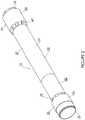
- the embodiment provides a housing 15 for accommodating the first tool portion 11 as it is deployed within the borehole, as shown in Figures 6 and 8 .
- the core tube 13 and the housing 15 form part of an assembly 17, which is shown in Figure 9 and which also includes a back-end portion 19.
- the back-end portion 19 is of standard wire line construction and is normally connected directly to core tube 13; however, in this embodiment, the housing 15 is configured for installation between the core tube 13 and the back- end portion 19.
- the housing 15 has a bottom end 16 adapted for connection to the upper end of the core tube 13, and an top end 18 adapted for connection to the back-end portion 19, as will be explained.
- the first tool portion 11 is also connected to the core tube 13 so that it record data relative to the orientation of the core tube and any core sample contained therein.
- the housing 15 comprises two parts, being lower body part 21 and an upper cap part 22.
- the two parts 21, 22 cooperate to define an inner compartment 23 adapted to receive and accommodate the first tool portion 11.
- the compartment is best seen in Figure 7 .
- the parts 21, 22 are selectively separable to provide access to the compartment 23. In the arrangement illustrated in Figure 5 , the two parts 21, 22 are shown in the separated condition.
- the lower body part 21 has an end 25 configured as a spigot 26, and the upper cap portion 22 has an adjacent end configured as a socket 27 in which the spigot 26 can be threadingly received to secure the two parts together.
- a sealing means 29 is provided to effect fluid-tight sealing engagement between the two parts 21, 22.
- the sealing means 29 comprises O-rings on the spigot 26.
- the housing 15 comprises three sections, being a first section 31, a second section 32 and a third section 33.
- the first and third sections 31, 33 comprise end sections, and the second section 32 comprises an intermediate section between the two end sections.
- the two parts 21, 22 cooperate to define the three sections 31, 32, and 33.
- the lower body part 21 defines the first section 31 which constitutes the lowermost section and which terminates at the bottom end.
- the upper cap part 22 defines the third section 33 which constitutes the uppermost section and which terminates at the top end 18.
- the lower body part 21 and the upper cap part 22 cooperate to define the intermediate second section 32'.
- the two end sections 31, 33 each have a generally circular outer periphery 35.
- the intermediate second section 32 also has a generally circular outer periphery 37.
- the outer periphery 37 of the intermediate second section 32 is of smaller diameter than the outer peripheries 35 of the two end sections 31, 33.
- the first end section 31 is configured for threaded engagement with the adjacent end of the core tube 13.
- the end section 31 is configured as a threaded coupling 41 having a thread formation 43 for threaded engagement with the adjacent end of the core tube 13 which has a matching threaded coupling.
- the threaded coupling 41 is of female configuration and the threaded formation 43 is a female thread.
- the first end section 31 incorporates a cavity 47 for communicating with the interior passage within the core tube 13 when the housing 15 is threadedly connected to the core tube 13.
- the cavity 47 has a peripheral wall 47a, a bottom end 47b which is open and which communicates with the bottom end 16 of the housing 15, and a top wall 47c.
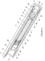
- first end section 31 is provided with a plurality of ports 49 which extend between the cavity 47 and the exterior of the housing 15 adjacent the intermediate second section 32, as best seen in Figure 7 of the drawings.
- first end section 31 is configured to provide a fluid flow path between the interior passage of the core tube 13 and the exterior of the housing 15 around the intermediate second section 32 thereof.
- the ports 49 are circumferentially spaced about the cavity 47, and extend outwardly from the cavity wall 47a and upwardly toward the top end 18
- the first end section 31 also incorporates a valve means 51 to permit fluid flow from the interior passage of the core tube 13 to the annular space 40 about the intermediate second section 32 of the housing 15, while inhibiting fluid flow in the reverse direction.
- the valve means 51 comprises a check-valve in the form of ball check-valve 53.
- the ball check-valve 53 comprises a spherical valve ball 55 and a valve seat 57 against which the valve ball 55 can sealingly engage.
- the valve seat 57 is provided around the periphery of the open end 47b of the cavity 47.
- the valve seat 57 is defined within a valve housing 59 connected to an inner portion 61 of the first end section 31.
- the inner portion 61 is adjacent the cavity 47 and at the bottom entry end 47b of the cavity 47, as shown in Figure 7 .
- the valve housing 59 incorporates a male end 63 for threaded engagement with the inner portion 61.
- the valve housing 59 cooperates with the inner cavity 47 to provide a cage for retaining valve ball 55 in position. While retained in position, the valve ball 55 is movable into and out of a sealing engagement with the valve seat 57 under the influence of fluid flow in accordance with known ball check-valve operation.
- the valve housing 59 is also configured to define the threaded coupling 41 having a thread formation 43 at end 16 for threaded engagement with the adjacent end of the core tube 13
- the valve means 15 is centrally located within the housing 15 and is sized to optimise fluid flow through the housing 15 to facilitate rapid descent of the assembly 17 in a borehole.
- the top wall 47c of the cavity 47 is configure to provide a recess 65 into which the valve ball 55 can be received when the check-valve 53 is open during descent of the housing 15.
- the valve ball 55 received and captively retained in the recess 65 under the influence of fluid flow through the cavity 47 during descent of the housing 15. With this arrangement, the valve ball 55 is constrained by the recess 65 centrally within cavity 47 and away from the ports 49 so as not to impede fluid flow through the cavity 47to the ports 49.
- the valve means 51 is operable to inhibit fluid flow in the reverse direction in order to isolate any core sample contained within the interior passage within the core tube 13 from the effects of fluid flow during ascent of the core tube.
- the third end section 33 which is at the top end 18, is configured for threaded engagement with the adjacent end of the back-end portion 19.
- the third end section 33 is configured as a threaded coupling 71 having a thread formation 73 for threaded engagement with the adjacent end of the back-end portion 19 which has a matching threaded coupling.
- the threaded coupling 71 is of male configuration and the threaded formation 73 is a male thread.
- the third end section 33 incorporates a cavity 77 for communicating with the interior of the back-end portion 19 when the housing 15 is threadedly connected to the back-end portion. Further, the third end section 33 is provided with a plurality of ports 79 which extend between the cavity 77 and the exterior of the housing 15 adjacent the intermediate second section 32, as best seen in Figure 7 . With this arrangement, the third end section 33 is configured to provide a fluid flow path between the exterior of the housing 15 around the intermediate second section 32 and the back-end portion 19.
- the housing 15 is installed between the core tube 13 and the back-end portion 19, as previously described to provide the assembly 17.
- the two parts 21, 22 of the housing 15 are separated to allow installation of the first tool portion 11 of the orientation device into the compartment 23 and then coupled together to encase the first tool portion within the compartment.
- the assembly 17 is then lowered down the drill rods within the borehole in conventional manner.
- fluid within the drill rods flows upwardly (relative to the descending assembly 17) along the interior passage of the core tube 11 and into the valve housing 59, causing the ball valve 55 to move away from the valve seat 57 and allow the fluid flow to enter the cavity 47 within the first end section 31 of the housing 25.
- the fluid flows through the ports 49 and into the annular space 40 surrounding the intermediate second section 32.
- the fluid flows along the annular space 40 to the ports 79 at the end section 33, from where the fluid flows through the ports 79 and into the central cavity 77.
- From the central cavity 77 the fluid flows through the hollow interior of the back-end portion 19 in the usual way.
- the flow path is depicted in Figure 8 by flow lines identified by reference numeral 80.
- the annular space 40 surrounding the intermediate second section 32 provided a fluid flow path between the ports 49 and the ports 79.
- fluid within the drill rods 14 is able to flow past the housing 15 as it descends within the drill rods, and so the presence of the housing 15 does not restrict fluid flow to such an extent to inhibit relatively rapid descent of the assembly 17.
- the core sample is retrieved in known manner.
- the relative fluid flow causes the valve ball 55 to sealingly engage the valve seat 57 to thereby close the check valve 53.
- the two parts 21, 22 of the housing 15 can be separated to provide access to the first tool portion 11.
- the second tool portion 12 can then be brought into cooperation with the first tool portion 11, as shown in Figure 10 , to receive and process the orientation data received from the first tool portion 11.
- the core sample can be removed from the core tube 11.
- the two parts 21, 22 of the housing 15 can then be brought together again to encase the first tool portion 11 within the housing so that the next core sampling operation can be performed when required.
- the present embodiment provides a simple yet highly effective way of enabling fluid to flow past the assembly 17 as it descends within a borehole (or more particularly within the drill rods), thereby facilitating rapid descent.
Landscapes
- Engineering & Computer Science (AREA)
- Geology (AREA)
- Life Sciences & Earth Sciences (AREA)
- Mining & Mineral Resources (AREA)
- Physics & Mathematics (AREA)
- General Life Sciences & Earth Sciences (AREA)
- Fluid Mechanics (AREA)
- Environmental & Geological Engineering (AREA)
- Geochemistry & Mineralogy (AREA)
- Geophysics (AREA)
- Mechanical Engineering (AREA)
- Sampling And Sample Adjustment (AREA)
- Branch Pipes, Bends, And The Like (AREA)
- Drilling And Boring (AREA)
- Quick-Acting Or Multi-Walled Pipe Joints (AREA)
- Geophysics And Detection Of Objects (AREA)
- Earth Drilling (AREA)
Claims (14)
- Gehäuse (15) zum Verbinden einer Untertagebaugruppe (17), dafür ausgelegt, innerhalb eines Bohrlochs aufgenommen zu werden, wobei das Gehäuse (17) einen ersten Bereich (31), einen zweiten Bereich (32) und einen dritten Bereich (33) umfasst, wobei der erste Bereich (31) für die Verbindung mit einem Abschnitt der Untertagebaugruppe (17) ausgelegt ist, der zweite Bereich (32) eine Kammer (23) zum Aufnehmen eines Untertagewerkzeugs oder einer Komponente davon definiert, und der dritte Bereich (33) von dem ersten Bereich (31) beabstandet ist, wobei der zweite Bereich (32) zwischen dem ersten und dem dritten Bereich (31, 33) angebracht ist, dadurch gekennzeichnet, dass der erste Bereich (31) eine Aussparung (47), wenigstens einen Anschluss (49) und einen ersten äußeren Umfang (35) aufweist, der zweite Bereich (32) einen zweiten äußeren Umfang (37) aufweist und der dritte Bereich (31) wenigstens einen Anschluss (79), eine weitere Aussparung (77) und einen dritten äußeren Umfang (35) aufweist, wobei der zweite äußere Umfang (37) der in Bezug auf den ersten und den dritten äußeren Umfang (35) von reduzierter Größe ist, wobei ein Raum (40) um den zweiten Bereich (32) festgelegt wird, um einen Weg für Fluidströmung um die Kammer (23) breitzustellen, wenn die Anordnung (17) innerhalb des Bohrlochs absinkt, wobei der erste Bereich (31) für fluidischen Austausch zwischen der Aussparung (47) und dem Raum (40) über den wenigstens einen Anschluss (49) in dem ersten Bereich (31), der sich zwischen der Aussparung (47) und dem Raum (40) erstreckt, konfiguriert ist, und der dritte Bereich (33) für fluidischen Austausch zwischen dem Raum (40) und der weiteren Aussparung (77) über den wenigstens einen Anschluss (79) in dem dritten Bereich (33), der sich zwischen dem Raum (40) und der weiteren Aussparung (77) erstreckt, konfiguriert ist.
- Gehäuse (15) nach einem der vorhergehenden Ansprüche, wobei der erste Bereich (31) für fluidischen Austausch zwischen einem Durchlass in dem Abschnitt der Untertageanordnung (17) und dem Fluidströmungsweg über die Aussparung (47) konfiguriert ist.
- Gehäuse (15) nach einem der vorhergehenden Ansprüche, wobei der dritte Bereich (33) zum Austausch mit einem weiteren Abschnitt der Untertageanordnung (17), in welchem ein weiterer Durchlass existiert, konfiguriert ist, und wobei der dritte Bereich (33) für fluidischen Austausch zwischen dem Fluidströmungsweg und dem weiteren Durchlass in dem weiteren Abschnitt der Untertageanordnung (17) über die weitere Aussparung (77) konfiguriert ist.
- Gehäuse (15) nach einem der vorhergehenden Ansprüche, umfassend wenigstens zwei Teile (21, 22), die zum Verbinden miteinander ausgelegt und selektiv trennbar sind, um Zugriff auf die Kammer (23) bereitzustellen.
- Gehäuse (15) nach einem der vorhergehenden Ansprüche, weiter umfassend ein Ventilmittel (51), das betreibbar ist, um es Fluid in einem Bohrloch zu erlauben, an der Untertageanordnung (17) vorbeizuströmen, wenn diese innerhalb des Bohrlochs absinkt, wobei es Fluidströmung an der Anordnung vorbei verhindert, wenn diese innerhalb des Bohrlochs aufsteigt.
- Gehäuse (15) nach Anspruch 5, wobei das Ventilmittel (51) ein Prüfventil (53) umfasst.
- Gehäuse (15) nach einem der Anspreche 5 oder 6, wobei das Ventilmittel (51) mit dem ersten Bereich (31) verknüpft sind.
- Gehäuse (15) nach Anspruch 5, 6 oder 7, wobei das Gehäusemittel (51) zentral angebracht und dimensioniert ist, um Strömung durch das Gehäuse zu optimieren, um schnelles Absinken zu vereinfachen.
- Gehäuse (15) nach einem der vorhergehenden Ansprüche, wobei das Gehäuse zur Verbindung mit einem rohrförmigen Abschnitt in der Untertageanordnung (17) ausgelegt ist, wobei der rohrförmige Abschnitt einen axialen Durchlass aufweist, welchen Fluid in einem Bohrloch durchlaufen kann, wenn sich die Anordnung innerhalb des Bohrlochs absenkt.
- Gehäuse (15) nach einem der Ansprüche 1 bis 8, wobei das Gehäuse (15) zur Verbindung mit einem Kernbohrer-Innenrohr ausgelegt ist, wobei das Innenrohr einen axialen Durchlass aufweist, durch welchen Fluid in einem Bohrloch strömen kann, wenn das Innenrohr und das damit verbundene Gehäuse sich innerhalb des Bohrlochs absenken.
- Gehäuse (15) nach einem der Ansprüche 1 bis 10, wobei der erste und dritte äußere Umfang (35) im Wesentlichen jeweils kreisförmig sind und der zweite äußere Umfang (37) im Wesentlichen kreisförmig ist, wobei der äußere Umfang (37) des zweiten Bereichs (32) von kleinerem Durchmesser ist als die äußeren Umfänge (35) des ersten und dritten Bereichs (31, 33), wobei der um den mittleren zweiten Bereich (32) etablierte Raum (40) im Wesentlichen ringförmig ist, und wobei die Anschlüsse (49, 79), im ersten und dritten Bereich (31, 33) in Austausch mit dem ringförmigen Raum stehen.
- Anordnung (17), die an einem Bohrloch entlang bewegbar ist, wobei die Anordnung (17) einen rohrförmigen Abschnitt (13) und ein mit dem rohrförmigen Abschnitt verbundenes Gehäuse (15) umfasst, wobei der rohrförmige Abschnitt (13) einen axialen Durchlass aufweist, welchen Fluid in dem Bohrloch durchlaufen kann, die Anordnung (17) innerhalb des Bohrlochs absenkt, wobei das Gehäuse (15) ein Gehäuse nach einem der vorhergehenden Ansprüche umfasst.
- Anordnung nach Anspruch 12, wobei der Fluidströmungsweg von einem Raum innerhalb des Bohrlochs um den zweiten Bereich (32) des Gehäuses (15) definiert ist.
- Kernbohranordnung, die entlang eines Bohrlochs bewegbar ist, wobei die Anordnung ein Kernbohrer-Innenrohr (13) und ein mit dem Kernbohrer-Innenrohr (13) verbundenes Gehäuse (15) umfasst, wobei das Kernbohrer-Innenrohr einen axialen Durchlass aufweist, welchen Fluid in dem Bohrloch durchlaufen kann, wenn die Anordnung innerhalb des Bohrlochs absinkt, wobei das Gehäuse (15) ein Gehäuse nach einem der vorhergehenden Ansprüche umfasst.
Priority Applications (1)
| Application Number | Priority Date | Filing Date | Title |
|---|---|---|---|
| EP17162073.5A EP3239454A1 (de) | 2009-02-12 | 2010-02-12 | Bohrlochwerkzeuggehäuse |
Applications Claiming Priority (2)
| Application Number | Priority Date | Filing Date | Title |
|---|---|---|---|
| AU2009900590A AU2009900590A0 (en) | 2009-02-12 | Downhole Tool Housing | |
| PCT/AU2010/000151 WO2010091471A1 (en) | 2009-02-12 | 2010-02-12 | Downhole tool housing |
Related Child Applications (1)
| Application Number | Title | Priority Date | Filing Date |
|---|---|---|---|
| EP17162073.5A Division EP3239454A1 (de) | 2009-02-12 | 2010-02-12 | Bohrlochwerkzeuggehäuse |
Publications (3)
| Publication Number | Publication Date |
|---|---|
| EP2396500A1 EP2396500A1 (de) | 2011-12-21 |
| EP2396500A4 EP2396500A4 (de) | 2014-05-07 |
| EP2396500B1 true EP2396500B1 (de) | 2017-03-22 |
Family
ID=42561328
Family Applications (2)
| Application Number | Title | Priority Date | Filing Date |
|---|---|---|---|
| EP17162073.5A Withdrawn EP3239454A1 (de) | 2009-02-12 | 2010-02-12 | Bohrlochwerkzeuggehäuse |
| EP10740846.0A Active EP2396500B1 (de) | 2009-02-12 | 2010-02-12 | Gehäuse für ein bohrlochwerkzeug |
Family Applications Before (1)
| Application Number | Title | Priority Date | Filing Date |
|---|---|---|---|
| EP17162073.5A Withdrawn EP3239454A1 (de) | 2009-02-12 | 2010-02-12 | Bohrlochwerkzeuggehäuse |
Country Status (13)
| Country | Link |
|---|---|
| US (1) | US9279320B2 (de) |
| EP (2) | EP3239454A1 (de) |
| AP (1) | AP3178A (de) |
| AR (1) | AR075417A1 (de) |
| AU (1) | AU2010213361B2 (de) |
| BR (1) | BRPI1005925A2 (de) |
| CA (1) | CA2752220C (de) |
| CL (1) | CL2011001985A1 (de) |
| ES (1) | ES2622152T3 (de) |
| MX (1) | MX350995B (de) |
| PT (1) | PT2396500T (de) |
| WO (1) | WO2010091471A1 (de) |
| ZA (1) | ZA201106477B (de) |
Families Citing this family (6)
| Publication number | Priority date | Publication date | Assignee | Title |
|---|---|---|---|---|
| US20120261189A1 (en) * | 2011-04-14 | 2012-10-18 | Longyear Tm, Inc. | Undisturbed core sampler |
| WO2013106885A1 (en) * | 2012-01-17 | 2013-07-25 | Globaltech Corporation Pty Ltd | Improvements to equipment and methods for downhole surveying and data acquisition for a drilling operation |
| CA3197754A1 (en) | 2014-04-21 | 2015-10-29 | Longyear Tm, Inc. | Core barrel head assembly with an integratedsample orientation tool and system for using same |
| KR102367055B1 (ko) * | 2015-03-19 | 2022-02-24 | 삼성전자주식회사 | 전자 장치 및 전자 장치에서의 배터리 정보 제공 방법 |
| FI4045761T3 (fi) * | 2019-10-17 | 2025-02-25 | Veracio Ltd | Näytteenottimen kärkikokoonpano |
| AU2021209301B2 (en) | 2021-07-29 | 2025-11-06 | Reflex Instruments Asia Pacific Pty Ltd | Downhole tool assembly for mounting to a core barrel assembly |
Citations (2)
| Publication number | Priority date | Publication date | Assignee | Title |
|---|---|---|---|---|
| US1614199A (en) * | 1923-04-23 | 1927-01-11 | William H Jones | Core drill |
| US1818981A (en) * | 1930-05-31 | 1931-08-18 | Rexford O Anderson | Core barrel valve |
Family Cites Families (13)
| Publication number | Priority date | Publication date | Assignee | Title |
|---|---|---|---|---|
| US474080A (en) * | 1892-05-03 | bullock | ||
| US1493112A (en) * | 1922-05-13 | 1924-05-06 | John E Elliott | Rotary core drill |
| US1563837A (en) * | 1922-08-12 | 1925-12-01 | Roland R Crum | Core drill |
| US1629026A (en) * | 1926-12-09 | 1927-05-17 | Boyde H Dye | Coring device |
| US2001764A (en) * | 1932-07-27 | 1935-05-21 | Howard W Stepp | Core drill and valve therefor |
| US2035887A (en) * | 1933-10-23 | 1936-03-31 | Globe Oil Tools Co | Valve for core barrels |
| US2313576A (en) * | 1940-05-06 | 1943-03-09 | Ralph A Phillips | Core drilling device |
| US3955633A (en) * | 1974-04-26 | 1976-05-11 | Mindrill Limited | Drill |
| SU956743A1 (ru) * | 1980-01-14 | 1982-09-07 | Всесоюзный Ордена Трудового Красного Знамени Научно-Исследовательский Институт Буровой Техники | Устройство дл отбора ориентированного керна |
| US5230390A (en) * | 1992-03-06 | 1993-07-27 | Baker Hughes Incorporated | Self-contained closure mechanism for a core barrel inner tube assembly |
| AUPM720194A0 (en) | 1994-08-01 | 1994-08-25 | Sds Pacific Pte Ltd | Locking a sample tube in a downhole hammer |
| US6644421B1 (en) | 2001-12-26 | 2003-11-11 | Robbins Tools, Inc. | Sonde housing |
| CA2949848C (en) | 2004-09-03 | 2020-11-03 | Australian Mud Company Ltd. | Core sample orientation |
-
2010
- 2010-02-12 CA CA2752220A patent/CA2752220C/en active Active
- 2010-02-12 US US13/201,253 patent/US9279320B2/en active Active
- 2010-02-12 AR ARP100100412A patent/AR075417A1/es not_active Application Discontinuation
- 2010-02-12 EP EP17162073.5A patent/EP3239454A1/de not_active Withdrawn
- 2010-02-12 AP AP2011005861A patent/AP3178A/xx active
- 2010-02-12 AU AU2010213361A patent/AU2010213361B2/en active Active
- 2010-02-12 WO PCT/AU2010/000151 patent/WO2010091471A1/en not_active Ceased
- 2010-02-12 EP EP10740846.0A patent/EP2396500B1/de active Active
- 2010-02-12 PT PT107408460T patent/PT2396500T/pt unknown
- 2010-02-12 ES ES10740846.0T patent/ES2622152T3/es active Active
- 2010-02-12 BR BRPI1005925-3A patent/BRPI1005925A2/pt not_active Application Discontinuation
- 2010-02-12 MX MX2011008521A patent/MX350995B/es active IP Right Grant
-
2011
- 2011-08-12 CL CL2011001985A patent/CL2011001985A1/es unknown
- 2011-09-05 ZA ZA2011/06477A patent/ZA201106477B/en unknown
Patent Citations (2)
| Publication number | Priority date | Publication date | Assignee | Title |
|---|---|---|---|---|
| US1614199A (en) * | 1923-04-23 | 1927-01-11 | William H Jones | Core drill |
| US1818981A (en) * | 1930-05-31 | 1931-08-18 | Rexford O Anderson | Core barrel valve |
Also Published As
| Publication number | Publication date |
|---|---|
| CA2752220C (en) | 2017-06-06 |
| CA2752220A1 (en) | 2010-08-19 |
| EP2396500A4 (de) | 2014-05-07 |
| ES2622152T3 (es) | 2017-07-05 |
| PT2396500T (pt) | 2017-04-11 |
| EP3239454A1 (de) | 2017-11-01 |
| MX350995B (es) | 2017-09-27 |
| CL2011001985A1 (es) | 2012-01-20 |
| AU2010213361A1 (en) | 2011-09-22 |
| AU2010213361B2 (en) | 2016-07-14 |
| AR075417A1 (es) | 2011-03-30 |
| ZA201106477B (en) | 2012-11-28 |
| EP2396500A1 (de) | 2011-12-21 |
| AP3178A (en) | 2015-03-31 |
| US20120031681A1 (en) | 2012-02-09 |
| BRPI1005925A2 (pt) | 2020-06-23 |
| MX2011008521A (es) | 2011-11-18 |
| AP2011005861A0 (en) | 2011-10-31 |
| US9279320B2 (en) | 2016-03-08 |
| WO2010091471A1 (en) | 2010-08-19 |
Similar Documents
| Publication | Publication Date | Title |
|---|---|---|
| EP2396500B1 (de) | Gehäuse für ein bohrlochwerkzeug | |
| US8286702B2 (en) | Wireless downhole tool positioning system | |
| US7624810B2 (en) | Ball dropping assembly and technique for use in a well | |
| US7661475B2 (en) | Drill pipe conveyance system for slim logging tool | |
| NO323165B1 (no) | Apparat for aktivering av brønnhullsverktøy | |
| EP3327248A1 (de) | Vertiefung für schwimmerventil | |
| MX2012004587A (es) | Junta tubular de desconexion instrumentada. | |
| CA2776145C (en) | Wireless pipe recovery and perforating system | |
| JPH0347473B2 (de) | ||
| US6138756A (en) | Milling guide having orientation and depth determination capabilities | |
| US9689252B2 (en) | Autonomous painted joint simulator and method to reduce the time required to conduct a subsea dummy run | |
| AU2016425367B2 (en) | Lateral deflector with feedthrough for connection to intelligent systems | |
| EP2588707B1 (de) | Rückholbare unterwasservorrichtung zum bop schutz und verfahren | |
| US6295867B1 (en) | Geological sample sub | |
| WO2016147056A2 (en) | Vertical subsea tree annulus and controls access | |
| US5474128A (en) | Telescoping conduits for increasing the fluid resistance of well production tubing inadvertently dropped in an oil or gas well | |
| US4393940A (en) | Retrievable float valve assembly | |
| RU2425946C1 (ru) | Скважинный разъединитель | |
| US10895122B2 (en) | Methods and systems for disconnecting casing |
Legal Events
| Date | Code | Title | Description |
|---|---|---|---|
| PUAI | Public reference made under article 153(3) epc to a published international application that has entered the european phase |
Free format text: ORIGINAL CODE: 0009012 |
|
| 17P | Request for examination filed |
Effective date: 20110909 |
|
| AK | Designated contracting states |
Kind code of ref document: A1 Designated state(s): AT BE BG CH CY CZ DE DK EE ES FI FR GB GR HR HU IE IS IT LI LT LU LV MC MK MT NL NO PL PT RO SE SI SK SM TR |
|
| DAX | Request for extension of the european patent (deleted) | ||
| A4 | Supplementary search report drawn up and despatched |
Effective date: 20140407 |
|
| RIC1 | Information provided on ipc code assigned before grant |
Ipc: G01V 3/18 20060101ALI20140401BHEP Ipc: E21B 25/16 20060101AFI20140401BHEP Ipc: E21B 47/01 20120101ALI20140401BHEP |
|
| 17Q | First examination report despatched |
Effective date: 20150224 |
|
| GRAP | Despatch of communication of intention to grant a patent |
Free format text: ORIGINAL CODE: EPIDOSNIGR1 |
|
| INTG | Intention to grant announced |
Effective date: 20160901 |
|
| RAP1 | Party data changed (applicant data changed or rights of an application transferred) |
Owner name: REFLEX TECHNOLOGY INTERNATIONAL PTY LTD |
|
| GRAJ | Information related to disapproval of communication of intention to grant by the applicant or resumption of examination proceedings by the epo deleted |
Free format text: ORIGINAL CODE: EPIDOSDIGR1 |
|
| STAA | Information on the status of an ep patent application or granted ep patent |
Free format text: STATUS: EXAMINATION IS IN PROGRESS |
|
| GRAR | Information related to intention to grant a patent recorded |
Free format text: ORIGINAL CODE: EPIDOSNIGR71 |
|
| GRAS | Grant fee paid |
Free format text: ORIGINAL CODE: EPIDOSNIGR3 |
|
| STAA | Information on the status of an ep patent application or granted ep patent |
Free format text: STATUS: GRANT OF PATENT IS INTENDED |
|
| GRAA | (expected) grant |
Free format text: ORIGINAL CODE: 0009210 |
|
| STAA | Information on the status of an ep patent application or granted ep patent |
Free format text: STATUS: THE PATENT HAS BEEN GRANTED |
|
| INTC | Intention to grant announced (deleted) | ||
| INTG | Intention to grant announced |
Effective date: 20170127 |
|
| AK | Designated contracting states |
Kind code of ref document: B1 Designated state(s): AT BE BG CH CY CZ DE DK EE ES FI FR GB GR HR HU IE IS IT LI LT LU LV MC MK MT NL NO PL PT RO SE SI SK SM TR |
|
| REG | Reference to a national code |
Ref country code: GB Ref legal event code: FG4D |
|
| REG | Reference to a national code |
Ref country code: CH Ref legal event code: EP |
|
| REG | Reference to a national code |
Ref country code: RO Ref legal event code: EPE |
|
| REG | Reference to a national code |
Ref country code: PT Ref legal event code: SC4A Ref document number: 2396500 Country of ref document: PT Date of ref document: 20170411 Kind code of ref document: T Free format text: AVAILABILITY OF NATIONAL TRANSLATION Effective date: 20170404 |
|
| REG | Reference to a national code |
Ref country code: AT Ref legal event code: REF Ref document number: 877999 Country of ref document: AT Kind code of ref document: T Effective date: 20170415 |
|
| REG | Reference to a national code |
Ref country code: IE Ref legal event code: FG4D |
|
| REG | Reference to a national code |
Ref country code: SE Ref legal event code: TRGR |
|
| REG | Reference to a national code |
Ref country code: DE Ref legal event code: R096 Ref document number: 602010040951 Country of ref document: DE |
|
| REG | Reference to a national code |
Ref country code: NO Ref legal event code: T2 Effective date: 20170322 |
|
| REG | Reference to a national code |
Ref country code: ES Ref legal event code: FG2A Ref document number: 2622152 Country of ref document: ES Kind code of ref document: T3 Effective date: 20170705 |
|
| REG | Reference to a national code |
Ref country code: NL Ref legal event code: MP Effective date: 20170322 |
|
| PG25 | Lapsed in a contracting state [announced via postgrant information from national office to epo] |
Ref country code: HR Free format text: LAPSE BECAUSE OF FAILURE TO SUBMIT A TRANSLATION OF THE DESCRIPTION OR TO PAY THE FEE WITHIN THE PRESCRIBED TIME-LIMIT Effective date: 20170322 Ref country code: LT Free format text: LAPSE BECAUSE OF FAILURE TO SUBMIT A TRANSLATION OF THE DESCRIPTION OR TO PAY THE FEE WITHIN THE PRESCRIBED TIME-LIMIT Effective date: 20170322 |
|
| REG | Reference to a national code |
Ref country code: LT Ref legal event code: MG4D |
|
| REG | Reference to a national code |
Ref country code: AT Ref legal event code: MK05 Ref document number: 877999 Country of ref document: AT Kind code of ref document: T Effective date: 20170322 |
|
| PG25 | Lapsed in a contracting state [announced via postgrant information from national office to epo] |
Ref country code: LV Free format text: LAPSE BECAUSE OF FAILURE TO SUBMIT A TRANSLATION OF THE DESCRIPTION OR TO PAY THE FEE WITHIN THE PRESCRIBED TIME-LIMIT Effective date: 20170322 |
|
| PG25 | Lapsed in a contracting state [announced via postgrant information from national office to epo] |
Ref country code: NL Free format text: LAPSE BECAUSE OF FAILURE TO SUBMIT A TRANSLATION OF THE DESCRIPTION OR TO PAY THE FEE WITHIN THE PRESCRIBED TIME-LIMIT Effective date: 20170322 |
|
| PG25 | Lapsed in a contracting state [announced via postgrant information from national office to epo] |
Ref country code: SK Free format text: LAPSE BECAUSE OF FAILURE TO SUBMIT A TRANSLATION OF THE DESCRIPTION OR TO PAY THE FEE WITHIN THE PRESCRIBED TIME-LIMIT Effective date: 20170322 Ref country code: CZ Free format text: LAPSE BECAUSE OF FAILURE TO SUBMIT A TRANSLATION OF THE DESCRIPTION OR TO PAY THE FEE WITHIN THE PRESCRIBED TIME-LIMIT Effective date: 20170322 Ref country code: EE Free format text: LAPSE BECAUSE OF FAILURE TO SUBMIT A TRANSLATION OF THE DESCRIPTION OR TO PAY THE FEE WITHIN THE PRESCRIBED TIME-LIMIT Effective date: 20170322 Ref country code: AT Free format text: LAPSE BECAUSE OF FAILURE TO SUBMIT A TRANSLATION OF THE DESCRIPTION OR TO PAY THE FEE WITHIN THE PRESCRIBED TIME-LIMIT Effective date: 20170322 |
|
| REG | Reference to a national code |
Ref country code: GR Ref legal event code: EP Ref document number: 20170401239 Country of ref document: GR Effective date: 20171023 |
|
| PG25 | Lapsed in a contracting state [announced via postgrant information from national office to epo] |
Ref country code: IS Free format text: LAPSE BECAUSE OF FAILURE TO SUBMIT A TRANSLATION OF THE DESCRIPTION OR TO PAY THE FEE WITHIN THE PRESCRIBED TIME-LIMIT Effective date: 20170722 Ref country code: SM Free format text: LAPSE BECAUSE OF FAILURE TO SUBMIT A TRANSLATION OF THE DESCRIPTION OR TO PAY THE FEE WITHIN THE PRESCRIBED TIME-LIMIT Effective date: 20170322 Ref country code: PL Free format text: LAPSE BECAUSE OF FAILURE TO SUBMIT A TRANSLATION OF THE DESCRIPTION OR TO PAY THE FEE WITHIN THE PRESCRIBED TIME-LIMIT Effective date: 20170322 |
|
| REG | Reference to a national code |
Ref country code: DE Ref legal event code: R097 Ref document number: 602010040951 Country of ref document: DE |
|
| PLBE | No opposition filed within time limit |
Free format text: ORIGINAL CODE: 0009261 |
|
| STAA | Information on the status of an ep patent application or granted ep patent |
Free format text: STATUS: NO OPPOSITION FILED WITHIN TIME LIMIT |
|
| PG25 | Lapsed in a contracting state [announced via postgrant information from national office to epo] |
Ref country code: DK Free format text: LAPSE BECAUSE OF FAILURE TO SUBMIT A TRANSLATION OF THE DESCRIPTION OR TO PAY THE FEE WITHIN THE PRESCRIBED TIME-LIMIT Effective date: 20170322 |
|
| 26N | No opposition filed |
Effective date: 20180102 |
|
| PG25 | Lapsed in a contracting state [announced via postgrant information from national office to epo] |
Ref country code: IT Free format text: LAPSE BECAUSE OF FAILURE TO SUBMIT A TRANSLATION OF THE DESCRIPTION OR TO PAY THE FEE WITHIN THE PRESCRIBED TIME-LIMIT Effective date: 20170322 Ref country code: SI Free format text: LAPSE BECAUSE OF FAILURE TO SUBMIT A TRANSLATION OF THE DESCRIPTION OR TO PAY THE FEE WITHIN THE PRESCRIBED TIME-LIMIT Effective date: 20170322 |
|
| PGFP | Annual fee paid to national office [announced via postgrant information from national office to epo] |
Ref country code: RO Payment date: 20180212 Year of fee payment: 9 Ref country code: ES Payment date: 20180301 Year of fee payment: 9 |
|
| PGFP | Annual fee paid to national office [announced via postgrant information from national office to epo] |
Ref country code: GR Payment date: 20180129 Year of fee payment: 9 Ref country code: PT Payment date: 20180207 Year of fee payment: 9 Ref country code: TR Payment date: 20180131 Year of fee payment: 9 Ref country code: BG Payment date: 20180131 Year of fee payment: 9 |
|
| REG | Reference to a national code |
Ref country code: DE Ref legal event code: R119 Ref document number: 602010040951 Country of ref document: DE |
|
| REG | Reference to a national code |
Ref country code: CH Ref legal event code: PL |
|
| PG25 | Lapsed in a contracting state [announced via postgrant information from national office to epo] |
Ref country code: MC Free format text: LAPSE BECAUSE OF FAILURE TO SUBMIT A TRANSLATION OF THE DESCRIPTION OR TO PAY THE FEE WITHIN THE PRESCRIBED TIME-LIMIT Effective date: 20170322 |
|
| REG | Reference to a national code |
Ref country code: BE Ref legal event code: MM Effective date: 20180228 |
|
| PG25 | Lapsed in a contracting state [announced via postgrant information from national office to epo] |
Ref country code: LU Free format text: LAPSE BECAUSE OF NON-PAYMENT OF DUE FEES Effective date: 20180212 Ref country code: CH Free format text: LAPSE BECAUSE OF NON-PAYMENT OF DUE FEES Effective date: 20180228 Ref country code: LI Free format text: LAPSE BECAUSE OF NON-PAYMENT OF DUE FEES Effective date: 20180228 |
|
| REG | Reference to a national code |
Ref country code: FR Ref legal event code: ST Effective date: 20181031 |
|
| PG25 | Lapsed in a contracting state [announced via postgrant information from national office to epo] |
Ref country code: DE Free format text: LAPSE BECAUSE OF NON-PAYMENT OF DUE FEES Effective date: 20180901 |
|
| PG25 | Lapsed in a contracting state [announced via postgrant information from national office to epo] |
Ref country code: FR Free format text: LAPSE BECAUSE OF NON-PAYMENT OF DUE FEES Effective date: 20180228 Ref country code: BE Free format text: LAPSE BECAUSE OF NON-PAYMENT OF DUE FEES Effective date: 20180228 |
|
| REG | Reference to a national code |
Ref country code: NO Ref legal event code: CHAD Owner name: REFLEX INSTRUMENTS ASIA PACIFIC PTY. LTD., AU |
|
| REG | Reference to a national code |
Ref country code: GB Ref legal event code: 732E Free format text: REGISTERED BETWEEN 20190711 AND 20190717 |
|
| PG25 | Lapsed in a contracting state [announced via postgrant information from national office to epo] |
Ref country code: RO Free format text: LAPSE BECAUSE OF NON-PAYMENT OF DUE FEES Effective date: 20190212 Ref country code: PT Free format text: LAPSE BECAUSE OF NON-PAYMENT OF DUE FEES Effective date: 20190812 |
|
| PG25 | Lapsed in a contracting state [announced via postgrant information from national office to epo] |
Ref country code: GR Free format text: LAPSE BECAUSE OF NON-PAYMENT OF DUE FEES Effective date: 20190904 Ref country code: BG Free format text: LAPSE BECAUSE OF NON-PAYMENT OF DUE FEES Effective date: 20190831 |
|
| PG25 | Lapsed in a contracting state [announced via postgrant information from national office to epo] |
Ref country code: MT Free format text: LAPSE BECAUSE OF NON-PAYMENT OF DUE FEES Effective date: 20180212 |
|
| REG | Reference to a national code |
Ref country code: ES Ref legal event code: FD2A Effective date: 20200330 |
|
| PG25 | Lapsed in a contracting state [announced via postgrant information from national office to epo] |
Ref country code: ES Free format text: LAPSE BECAUSE OF NON-PAYMENT OF DUE FEES Effective date: 20190213 |
|
| PG25 | Lapsed in a contracting state [announced via postgrant information from national office to epo] |
Ref country code: HU Free format text: LAPSE BECAUSE OF FAILURE TO SUBMIT A TRANSLATION OF THE DESCRIPTION OR TO PAY THE FEE WITHIN THE PRESCRIBED TIME-LIMIT; INVALID AB INITIO Effective date: 20100212 |
|
| PG25 | Lapsed in a contracting state [announced via postgrant information from national office to epo] |
Ref country code: CY Free format text: LAPSE BECAUSE OF FAILURE TO SUBMIT A TRANSLATION OF THE DESCRIPTION OR TO PAY THE FEE WITHIN THE PRESCRIBED TIME-LIMIT Effective date: 20170322 Ref country code: MK Free format text: LAPSE BECAUSE OF NON-PAYMENT OF DUE FEES Effective date: 20170322 |
|
| PG25 | Lapsed in a contracting state [announced via postgrant information from national office to epo] |
Ref country code: TR Free format text: LAPSE BECAUSE OF NON-PAYMENT OF DUE FEES Effective date: 20190212 |
|
| P01 | Opt-out of the competence of the unified patent court (upc) registered |
Effective date: 20230609 |
|
| P02 | Opt-out of the competence of the unified patent court (upc) changed |
Effective date: 20230620 |
|
| PGFP | Annual fee paid to national office [announced via postgrant information from national office to epo] |
Ref country code: SE Payment date: 20260121 Year of fee payment: 17 |
|
| PGFP | Annual fee paid to national office [announced via postgrant information from national office to epo] |
Ref country code: GB Payment date: 20260121 Year of fee payment: 17 |
|
| PGFP | Annual fee paid to national office [announced via postgrant information from national office to epo] |
Ref country code: NO Payment date: 20260123 Year of fee payment: 17 Ref country code: IE Payment date: 20260123 Year of fee payment: 17 |
|
| PGFP | Annual fee paid to national office [announced via postgrant information from national office to epo] |
Ref country code: FI Payment date: 20260121 Year of fee payment: 17 |