EP2396479B1 - Multi-directional torsional hysteretic damper (mthd) - Google Patents
Multi-directional torsional hysteretic damper (mthd) Download PDFInfo
- Publication number
- EP2396479B1 EP2396479B1 EP09788649.3A EP09788649A EP2396479B1 EP 2396479 B1 EP2396479 B1 EP 2396479B1 EP 09788649 A EP09788649 A EP 09788649A EP 2396479 B1 EP2396479 B1 EP 2396479B1
- Authority
- EP
- European Patent Office
- Prior art keywords
- yielding
- arm
- cores
- arms
- welded
- Prior art date
- Legal status (The legal status is an assumption and is not a legal conclusion. Google has not performed a legal analysis and makes no representation as to the accuracy of the status listed.)
- Not-in-force
Links
Images


Classifications
-
- E—FIXED CONSTRUCTIONS
- E01—CONSTRUCTION OF ROADS, RAILWAYS, OR BRIDGES
- E01D—CONSTRUCTION OF BRIDGES, ELEVATED ROADWAYS OR VIADUCTS; ASSEMBLY OF BRIDGES
- E01D19/00—Structural or constructional details of bridges
- E01D19/04—Bearings; Hinges
- E01D19/042—Mechanical bearings
- E01D19/043—Roller bearings
-
- F—MECHANICAL ENGINEERING; LIGHTING; HEATING; WEAPONS; BLASTING
- F16—ENGINEERING ELEMENTS AND UNITS; GENERAL MEASURES FOR PRODUCING AND MAINTAINING EFFECTIVE FUNCTIONING OF MACHINES OR INSTALLATIONS; THERMAL INSULATION IN GENERAL
- F16F—SPRINGS; SHOCK-ABSORBERS; MEANS FOR DAMPING VIBRATION
- F16F15/00—Suppression of vibrations in systems; Means or arrangements for avoiding or reducing out-of-balance forces, e.g. due to motion
- F16F15/02—Suppression of vibrations of non-rotating, e.g. reciprocating systems; Suppression of vibrations of rotating systems by use of members not moving with the rotating systems
- F16F15/04—Suppression of vibrations of non-rotating, e.g. reciprocating systems; Suppression of vibrations of rotating systems by use of members not moving with the rotating systems using elastic means
- F16F15/06—Suppression of vibrations of non-rotating, e.g. reciprocating systems; Suppression of vibrations of rotating systems by use of members not moving with the rotating systems using elastic means with metal springs
- F16F15/063—Suppression of vibrations of non-rotating, e.g. reciprocating systems; Suppression of vibrations of rotating systems by use of members not moving with the rotating systems using elastic means with metal springs with bars or tubes used as torsional elements
Definitions
- the invention relates to seismic resistant (anti-seismic) devices and, in particular, to seismic hysteretic dampers, used to protect the structures against severe earthquakes. These devices are installed at points where large displacements are expected due to earthquake shakings, such as between the bridge deck and bearing points (pier cap beam).
- Dampers are energy dissipaters. They dissipate the kinetic energy swept into them due to the relative motion of two (mounting) ends. Speaking in terms of force-displacement rather than energy, they work by exerting a force upon their moving ends which always opposes the relative displacement of two ends. We shall call this force that can be used as a measure of energy dissipation capacity of the damper, the 'reaction force' of the damper. In hysteretic dampers such property is achieved by utilizing the hysteretic behavior in metals.
- the available multi-directional hysteretic dampers for bridges in the prior art are, a device composed of Crescent Moon Shaped elements as described in US 5,806,250 and Tapered Pin energy dissipating elements and device composed of C-clamps as described in US 5,509,238 .
- Other hysteretic dampers are also available in the prior art, though they do not have multi-directional action, such as Butterfly-Shaped energy dissipating elements.
- shock absorbing mounting in the prior art is basically a vibration isolator as described in US 3,730,463 with a self-centering annular rubber working as the spring-damper element.
- the use of rubber, as in the case of bridge elastomeric isolators, is to create a soft connection and to increase the natural period of the supported structure and hence, making it less vulnerable to shock type movements.
- the function of a hysteretic damper like the one presented in the present invention is not the isolation of the structure rather, increasing energy dissipation by providing a dissipative force through yielding of metals.
- the shock absorbing mounting can possesses slight damping, it is not a hysteretic damper and as being a self-centering system, it cannot have a large damping.
- C-shaped (or U-shaped) plates are arranged into a multi-directional device in a symmetric arrangement.
- C-shaped plates provide hysteretic energy dissipation as they bend and yield along the width, in a folding/unfolding deflection.
- Tapered pin elements are straight beams with circular sections variable along the length, so that bending causes uniform yielding along the height, avoiding strain concentration. Because of their 'inherent' symmetry along all directions, they can be simply arranged into a multi directional damper system without the need for any mechanism to bring them into multi directional action.
- the aim of the present invention is to develop a multidirectional hysteretic damper, better or as effective in behavior as the available hysteretic dampers and economical to manufacture.
- the main difference between the invented device and the available ones can be summarized as:
- the basic parts of the present invention consist of;
- the said hysteretic damper device related to the present invention consists of three main parts;
Landscapes
- Engineering & Computer Science (AREA)
- Mechanical Engineering (AREA)
- Architecture (AREA)
- Civil Engineering (AREA)
- Structural Engineering (AREA)
- Bridges Or Land Bridges (AREA)
- Buildings Adapted To Withstand Abnormal External Influences (AREA)
- Vibration Prevention Devices (AREA)
- Vibration Dampers (AREA)
- Springs (AREA)
Description
- The invention relates to seismic resistant (anti-seismic) devices and, in particular, to seismic hysteretic dampers, used to protect the structures against severe earthquakes. These devices are installed at points where large displacements are expected due to earthquake shakings, such as between the bridge deck and bearing points (pier cap beam).
- Dampers are energy dissipaters. They dissipate the kinetic energy swept into them due to the relative motion of two (mounting) ends. Speaking in terms of force-displacement rather than energy, they work by exerting a force upon their moving ends which always opposes the relative displacement of two ends. We shall call this force that can be used as a measure of energy dissipation capacity of the damper, the 'reaction force' of the damper. In hysteretic dampers such property is achieved by utilizing the hysteretic behavior in metals.
- The available multi-directional hysteretic dampers for bridges in the prior art are, a device composed of Crescent Moon Shaped elements as described in
US 5,806,250 and Tapered Pin energy dissipating elements and device composed of C-clamps as described inUS 5,509,238 . Other hysteretic dampers are also available in the prior art, though they do not have multi-directional action, such as Butterfly-Shaped energy dissipating elements. - Another shock absorbing mounting in the prior art is basically a vibration isolator as described in
US 3,730,463 with a self-centering annular rubber working as the spring-damper element. The use of rubber, as in the case of bridge elastomeric isolators, is to create a soft connection and to increase the natural period of the supported structure and hence, making it less vulnerable to shock type movements. The function of a hysteretic damper like the one presented in the present invention, on the other hand, is not the isolation of the structure rather, increasing energy dissipation by providing a dissipative force through yielding of metals. Although the shock absorbing mounting can possesses slight damping, it is not a hysteretic damper and as being a self-centering system, it cannot have a large damping. - In multidirectional devices composed of crescent moon shaped energy dissipaters, Italian patent No.
MI96A1447 - In the device composed of C clamps, C-shaped (or U-shaped) plates are arranged into a multi-directional device in a symmetric arrangement. C-shaped plates provide hysteretic energy dissipation as they bend and yield along the width, in a folding/unfolding deflection.
- Tapered pin elements are straight beams with circular sections variable along the length, so that bending causes uniform yielding along the height, avoiding strain concentration. Because of their 'inherent' symmetry along all directions, they can be simply arranged into a multi directional damper system without the need for any mechanism to bring them into multi directional action.
- The main differences between the invented device (MTHD) and the aforementioned existing devices are explained in the following section.
- The aim of the present invention is to develop a multidirectional hysteretic damper, better or as effective in behavior as the available hysteretic dampers and economical to manufacture. As far as the behavior is concerned, the main difference between the invented device and the available ones can be summarized as:
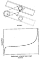
- 1. Variable post-elastic stiffness as a result of its special working mechanism which creates a geometric hardening effect which will be explained subsequently and is shown in graph in
Figure 13 , - 2. Easily adjustable arm (and rail) length allows for easily adjustable properties of the device: reaction force and maximum allowable displacement.
- 3. The device allows for the relative vertical displacements between the top and bottom anchoring points without any interference of such displacements with the intended behavior of the system in the horizontal direction.
- Although the use of cylindrical steel cores as hysteretic damping elements is known in the prior art, the design through which they are assembled into a multi-directional hysteretic damper is the new and unique feature of the present invention.
- The basic parts of the present invention consist of;
- Yielding cores with arm assembly (composed of
parts - A central supporting structure (composed of
parts 5, 6), - A rail system (composed of
parts 10, 11). - In order to explain the present invention in more detail, necessary figures have been prepared and attached to the description. The list and definition of the figures are given below.
-
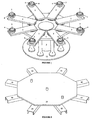
Figure 1 . 3D isometric view of the device with the rail system removed to allow for a better view of all the parts underneath, -
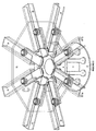
Figure 2 . 3D isometric view of the rail system, -
Figure 3 . 3D isometric view of the device with the overlaid sketch of rail system, -
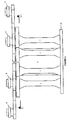
Figure 4 . Side view of the device with the rail system removed, -
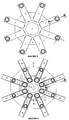
Figure 5 . Top view of the device with the rail system removed, -
Figure 6 . Top view of the entire device with all the parts showing (no hidden lines), -
Figure 7 . Cutaway view S1-S1 according toFigure 4 , -
Figure 8 . Cutaway view S2-S2 according toFigure 5 , -
Figure 9 . S3-S3 view according toFigure 6 , -
Figure 10 . Rail system, bottom view, -
Figure 11 . Rail system, top view. -
Figure 12 . One of the arms and its corresponding rail shown in undisplaced and displaced positions. -
Figure 13 . Force-displacement diagram of the device when the displacement is imposed in the direction of one of the rails (any) and with the assumption of elasto-plastic behavior for the steel. -
- 1 Yielding core,
- 2 Arm,
- 3 Core ball bearing is an ordinary steel ball bearing used to create the hinge connection between the core (1) and plate diaphragm (6). Since it is used at the core-diaphragm connection, we may call it 'core' ball bearing to distinguish it from arm ball bearing,
- 4 Arm ball bearing is an ordinary steel ball bearing used to create the roller hinge connection between the arm (2) and rail (10),
- 5 Supporting column,
- 6 Plate diaphragm, in the shape of an octagon or a circle, with circular holes,
- 7 Solid, cylindrical, mountingshaft(s) welded to the arm for mounting the arm ball bearing,
- 8 Upper hollow cylindrical ring(s) welded at the top to the cylindrical shaft to hold the arm ball bearings in place. Also any other type of attachment such as a pin(s) can be used instead of upper hollow cylindrical ring(s),
- 9 Bottom hollow cylindrical ring(s) to hold the arm ball bearing in place. Also any other type of attachment such as a pin(s) can be used instead of bottom hollow cylindrical ring(s),
- 10 Rail(s), there are eight of them, as part of the rail system. Guide rails for arm ball bearing(s).
- 11 Octagonal top plate (a part of the rail system) with slits (or any other appropriate arrangement of slits depending on the type of connection) to allow for top connection of the device (to bridge deck),
- 12 Base plate, to connect the entire device to the base (pier cap beam).
- The said hysteretic damper device related to the present invention consists of three main parts;
- 1. The Yielding Cores: Along with the arm assembly which includes a steel ball bearing (4) to create a roller hinge type connection between the arm (2) and the rail system and allow for frictionless movement of the arm (2) end inside the rail (10). The arm (2) is welded to the core (1) on one end and in the other end has a cylindrical solid shaft (7) welded to it which serves as a mounting axis for the arm ball bearing (4), all shown in
Figure 8 . There are also two rings (8, 9) on the top and bottom sides of the arm ball bearing (4) to fix it in place. Also any other type of attachment such as a pin(s) can be used instead of upper and bottom hollow cylindrical ring(s) (8, 9). The upper ring (8) is welded to the mounting shaft (7). The yielding cores (1) are energy dissipation elements of the said hysteretic damper of the present invention and are made of steel. The cores (1) yield, mostly due to large torsional shear stresses, and dissipate energy as the arms (2) travel back and forth. The yielding cores (1) are welded to a base plate (12), thus the entire device (hysteretic damper) can be attached to the pier cap beam of the bridge through the base plate (12). - 2. The Supporting Structure: The Supporting Structure is composed of a central solid steel supporting column (5) and a plate diaphragm (6) welded to it. The plate diaphragm (6) will be connected to the yielding cores (1) through core ball bearings (3). The core ball bearings (3) are incorporated to create a (torsional) hinge connection between the yielding cores (1) and the plate diaphragm (6), allowing for free twisting of the cores (1). The main function of the supporting column (5) is to support the yielding cores (1) against bending. Due to its large lateral stiffness and its parallel connection with the cores (1), the central supporting column (5) will take the major share of the bending moment and thus preventing large bending stresses in the yielding cores (1) which are intended to yield in nearly pure torsional shear.
The central supporting column (5) can be in any other shape, such as a box or an octagonal prism as long as it provides the necessary lateral stiffness. The central supporting column (5) will be welded to the base plate (12). The plate diaphragm's (6) connection to the supporting column (5) is also by welding at the top and bottom of the central hole of the plate diaphragm (6). - 3. The Rail System: The rail system facilitates the connection between the bridge deck and the arms (2). The rail system will be attached to the deck through pins and holes and, if required, a shock transmission unit. It is composed of a top octagonal plate (11) with slotted holes on it and rails (10) welded to this plate (11). The rails (10) can be steel plates welded together to form a channel section or, in case rolled channel sections with suitable dimensions are available, can be used as rails (10). Depending on the case, side stiffeners might be needed to laterally stiffen the cantilever part of the rail channels. The connection of the top octagonal plate (11) to the deck is made by bars (pins) embedded inside the concrete deck of the bridge.
The rail system along with the arm ball bearings (4), forms the desired connection (roller hinge type connection) between the arm (2) ends and the bridge deck. With this type of a connection, each arm (2) will always be displaced laterally (relative to its corresponding rail) regardless of the movement direction of the bridge deck and the arm (2) does not need to follow the component of the deck displacement along the rail (10). This is true for all eight rails (10). As illustrated inFigure 12 , at the undeformed position, each arm (2) is parallel to its rail (10). As the displacement is imposed on the device, the arms (2) rotate and the angle, θ, between the arm (2) and its rail (10) increases. Since the arm (2) has to twist the yielding core (1) as it rotates, a shear force (V) will be created in the arm (2), perpendicular to it (Figure 12 ). This shear force must be balanced by the component of the force F normal to the arm (2) at the arm ball bearing-rail (arm end and rail) interface as shown inFigure 12 . This force, due to the presence of the arm ball bearing (4), is always perpendicular to the rail (10). However, its two components along and perpendicular to the arm (2) depend on the angle, θ, between the arm (2) and its rail (10):

This means that for a shear force V (that is the force effective in creating a torsional moment in the core) to be created in the arm (2), the force, F, must be equal to:
As the angle, θ, increases, even if V remains constant (assuming an elasto-plastic behavior for steel), F will increase, giving the device its geometric hardening capability. It should be mentioned that the sum of the component of these forces (F) along the displacement direction, coming from all the eight rails (10) is equal to the reaction force of the hysteretic damper device. That is, the reaction force of the device is dependant on its displacement level even in plastic range and elasto-plastic material behavior. This hardening behavior is shown inFigure 13 . Also, this means that the displacement cannot exceed a certain limit. Theoretically, the limiting displacement is equal to the length of the arm (2). This displacement corresponds to θ = 90°. However, since at angles close to 90° the axial force generated in the arm (2) and the force, F, will be extremely large, the practical limit to this displacement can be set to, say, "arm length X sin(60)", corresponding to a maximum rotation of 60°. Considering some specific cases, if the anticipated displacement in the bridge deck should increase above this amount, a larger hysteretic device should be considered.
Claims (1)
- Multi-Directional Torsional Hysteretic Damper as an anti-seismic device of hysteretic type with multi-directional action for protection of structures against earthquakes characterized in that, it is composed of;• at least eight yielding identical cores (1), in the shape of variable-diameter cylinder, which can yield, serving as energy dissipating elements by yielding due to large torsional shear stresses created via arms (2) welded to them, while the arms rotate back and forth and create torsion in the yielding cores (1), with each of the yielding cores (1) having one arm (2) welded to it at its top and with each of the yielding cores (1) being welded to a base plate (12) at its bottom and maintaining a torsional hinge connection with a plate diaphragm (6), in the shape of an octagon, through the use of core ball bearings (3) at the yielding cores - plate diaphragm (6) connection,• a supporting structure composed of a supporting column (5) and the plate diaphragm (6), the function of which is to support the yielding cores (1) against bending by taking the major share of the bending moment and thus preventing excessive bending in the yielding cores (1) which are intended to yield in torsion while being twisted by the rotation of the arms,• a rail system comprising identical rails (10) in the shape of a channel section in the same number as the yielding cores (1) plus an octagonal top plate (11), with the rails (10) welded to the top plate (11) while being positioned parallel to the arms (2), the function of which are guiding the movement of the arms (2) at the arm's end points where arm ball bearings (4) are provided to create, in combination with the rails, a roller hinge type connection between the arms (2) ends and the structure to be protected,• the arm ball bearings (4) being mounted on cylindrical mounting shafts (7) at the end points of arms (2) and being held in place by upper hollow cylindrical rings (8) and bottom hollow cylindrical rings (9) while the upper hollow cylindrical rings (8) are welded at top to the cylindrical mounting shafts (7),• top plate (11) being provided with slotted holes which provide the connection of the Multi-Directional Torsional Hysteretic Damper to a bridge deck.
Applications Claiming Priority (1)
| Application Number | Priority Date | Filing Date | Title |
|---|---|---|---|
| PCT/TR2009/000027 WO2010093337A1 (en) | 2009-02-16 | 2009-02-16 | Multi-directional torsional hysteretic damper (mthd) |
Publications (2)
| Publication Number | Publication Date |
|---|---|
| EP2396479A1 EP2396479A1 (en) | 2011-12-21 |
| EP2396479B1 true EP2396479B1 (en) | 2015-09-23 |
Family
ID=41128130
Family Applications (1)
| Application Number | Title | Priority Date | Filing Date |
|---|---|---|---|
| EP09788649.3A Not-in-force EP2396479B1 (en) | 2009-02-16 | 2009-02-16 | Multi-directional torsional hysteretic damper (mthd) |
Country Status (8)
| Country | Link |
|---|---|
| US (1) | US8438795B2 (en) |
| EP (1) | EP2396479B1 (en) |
| JP (1) | JP5424431B2 (en) |
| CN (1) | CN102317548B (en) |
| EA (1) | EA021188B1 (en) |
| ES (1) | ES2557307T3 (en) |
| UA (1) | UA100799C2 (en) |
| WO (1) | WO2010093337A1 (en) |
Families Citing this family (25)
| Publication number | Priority date | Publication date | Assignee | Title |
|---|---|---|---|---|
| WO2015110497A1 (en) * | 2014-01-24 | 2015-07-30 | Girardini S.R.L. | Dissipator |
| CN104196953B (en) * | 2014-08-13 | 2016-08-24 | 同济大学建筑设计研究院(集团)有限公司 | The tuning granule damper that a kind of anti-longitudinal axis reverses |
| US9777492B2 (en) * | 2015-01-19 | 2017-10-03 | Cor-Form, Llc | Core form device |
| US10024063B2 (en) | 2016-03-01 | 2018-07-17 | Denis P. Friel | Weep screed |
| TR201607751A2 (en) * | 2016-06-08 | 2017-12-21 | Ali Salem Milani | Torsional Hysteretic Dumper |
| CN106593056A (en) * | 2016-12-07 | 2017-04-26 | 北京工业大学 | Rotary-type straight-guiderail tension-resisting limiting shock isolating device |
| US11136778B1 (en) | 2017-05-12 | 2021-10-05 | Arrowhead Center, Inc. | Adaptive self-centering apparatus and method for seismic and wind protection of structures |
| CN107600102B (en) * | 2017-09-26 | 2019-03-29 | 西南交通大学 | A kind of three-dimensional multistage energy absorption device of rail vehicle |
| US10533324B2 (en) | 2017-11-30 | 2020-01-14 | Alabama Metal Industries Corporation | Below top of wall ventilation screed device and assembly |
| US11180913B2 (en) | 2017-11-30 | 2021-11-23 | Alabama Metal Industries Corporation | Top of wall ventilation screed device and assembly |
| US10669721B2 (en) | 2017-12-18 | 2020-06-02 | Alabama Metal Industries Corporation | Flashing device assembly |
| EP3707322A4 (en) * | 2018-02-09 | 2021-03-17 | Murat Dicleli | Multidirectional adaptive re-centering torsion isolator |
| JP7147274B2 (en) * | 2018-06-04 | 2022-10-05 | 株式会社大林組 | Damping structure and damping method |
| CN108951907B (en) * | 2018-07-19 | 2020-04-28 | 同济大学 | Combined type multidirectional friction damper |
| US10731335B2 (en) | 2018-08-03 | 2020-08-04 | Alabama Metal Industries Corporation | Top of wall ventilation screed device and assembly |
| US10753083B2 (en) | 2018-11-19 | 2020-08-25 | Alabama Metal Industries Corporation | Below top of wall ventilation screed device and assembly |
| USD923821S1 (en) | 2018-11-27 | 2021-06-29 | Alabama Metal Industries Corporation | Top of wall ventilation screed device |
| USD940349S1 (en) | 2018-11-27 | 2022-01-04 | Alabama Metal Industries Corporation | Below top of wall ventilation screed device |
| CN109487980B (en) * | 2018-12-03 | 2024-05-24 | 河南民生特种装备有限公司 | Vibration isolation floor supported by crank arm |
| CN109707139B (en) * | 2019-01-29 | 2024-07-26 | 河南民生特种装备有限公司 | Shock insulation floor supported by double crank arms |
| USD940350S1 (en) | 2019-07-11 | 2022-01-04 | Alabama Metal Industries Corporation | Vented finish bead |
| USD979099S1 (en) | 2019-08-22 | 2023-02-21 | Alabama Metal Industries Corporation | Ventilation screed device |
| USD973912S1 (en) | 2019-08-30 | 2022-12-27 | Alabama Metal Industries Corporation | Ventilation screed device |
| USD1033680S1 (en) | 2020-11-13 | 2024-07-02 | Alabama Metal Industries Corporation | Self-adhering bead device |
| CN113235404B (en) * | 2021-06-30 | 2022-09-27 | 重庆交通大学 | Assembled steel structure shock insulation bent cap |
Family Cites Families (17)
| Publication number | Priority date | Publication date | Assignee | Title |
|---|---|---|---|---|
| CH515430A (en) | 1970-05-06 | 1971-11-15 | Bbc Brown Boveri & Cie | Device for installation between a foundation connected to the earth and the foot part of a device to keep mechanical shock movements away from the device |
| GB1374880A (en) * | 1971-12-21 | 1974-11-20 | Daimler Benz Ag | Bumper assemblies for vehicles |
| JPS6288836A (en) * | 1985-10-09 | 1987-04-23 | Mitsubishi Electric Corp | Earthquake vibration damper |
| US4633628A (en) * | 1985-10-31 | 1987-01-06 | University Of Utah | Device for base isolating structures from lateral and rotational support motion |
| US4712938A (en) * | 1986-01-13 | 1987-12-15 | Foster Wheeler Energy Corporation | Expansion seal assembly |
| JPS6443643A (en) * | 1987-08-12 | 1989-02-15 | Tokico Ltd | Earthquake damping apparatus |
| US4953330A (en) * | 1987-12-01 | 1990-09-04 | Mitsui Kensetsu Kabushiki Kaisha | Damping device in a structure and damping construction and damping method using those devices |
| JPH06229143A (en) * | 1993-01-29 | 1994-08-16 | Nippon Steel Corp | Damping mechanism using friction force |
| IT1262385B (en) * | 1993-08-03 | 1996-06-19 | Tis Tech Idraulico Stradali | MULTIDIRECTIONAL MECHANICAL ENERGY DISPERSER PARTICULARLY SUITABLE FOR THE BINDING OF STRUCTURES IN SEISMIC AREA. |
| IT1283147B1 (en) | 1996-07-12 | 1998-04-07 | Fip Ind | MULTIDIRECTIONAL ANTI-SEISMIC MECHANICAL DEVICE WITH HYSTERETIC BEHAVIOR, PARTICULARLY SUITABLE FOR INSULATION AT THE BASE OF |
| JP2001303590A (en) * | 2000-04-24 | 2001-10-31 | Nkk Corp | Pile foundation structure |
| CN2538841Y (en) * | 2002-04-04 | 2003-03-05 | 毅强企业股份有限公司 | Bridge vibration-proof drawing-resisting device |
| CN100434603C (en) * | 2002-08-06 | 2008-11-19 | 杨洪 | Building insulating vibration -isolating system |
| US6799400B2 (en) * | 2003-01-15 | 2004-10-05 | Kuo-Jung Chuang | Earthquake shock damper |
| RU2325475C2 (en) * | 2005-12-19 | 2008-05-27 | Зао "Геомост" | Anti-seismic bridge |
| US7762030B2 (en) * | 2006-09-12 | 2010-07-27 | Espinosa Thomas M | Hold down system |
| KR100820001B1 (en) * | 2008-01-08 | 2008-04-08 | 조영철 | Bridge bearing with a damper member |
-
2009
- 2009-02-16 US US13/201,451 patent/US8438795B2/en not_active Expired - Fee Related
- 2009-02-16 JP JP2011550099A patent/JP5424431B2/en not_active Expired - Fee Related
- 2009-02-16 UA UAA201109999A patent/UA100799C2/en unknown
- 2009-02-16 EP EP09788649.3A patent/EP2396479B1/en not_active Not-in-force
- 2009-02-16 EA EA201101176A patent/EA021188B1/en not_active IP Right Cessation
- 2009-02-16 CN CN200980156834.9A patent/CN102317548B/en not_active Expired - Fee Related
- 2009-02-16 WO PCT/TR2009/000027 patent/WO2010093337A1/en active Application Filing
- 2009-02-16 ES ES09788649.3T patent/ES2557307T3/en active Active
Also Published As
| Publication number | Publication date |
|---|---|
| JP2012518137A (en) | 2012-08-09 |
| WO2010093337A1 (en) | 2010-08-19 |
| ES2557307T3 (en) | 2016-01-25 |
| EA201101176A1 (en) | 2012-01-30 |
| UA100799C2 (en) | 2013-01-25 |
| CN102317548B (en) | 2014-07-02 |
| JP5424431B2 (en) | 2014-02-26 |
| EP2396479A1 (en) | 2011-12-21 |
| US8438795B2 (en) | 2013-05-14 |
| US20120066986A1 (en) | 2012-03-22 |
| EA021188B1 (en) | 2015-04-30 |
| CN102317548A (en) | 2012-01-11 |
Similar Documents
| Publication | Publication Date | Title |
|---|---|---|
| EP2396479B1 (en) | Multi-directional torsional hysteretic damper (mthd) | |
| JP6594062B2 (en) | Slide mechanism of bridge seismic device | |
| US20020166301A1 (en) | Directional sliding pendulum seismic isolation systems and articulated sliding assemblies therefor | |
| US11384558B2 (en) | Multidirectional adaptive re-centering torsion isolator | |
| KR200473182Y1 (en) | Friction pendulum bearing | |
| KR20090085408A (en) | Bridge bearing using the shape-memory-alloy | |
| US20230212831A1 (en) | Damper and damper system for damping relative lateral movement between a tensioned cable and a support structure | |
| JP5757197B2 (en) | Damping structure | |
| JP6099882B2 (en) | Seismic improvement method for sluice pillar of dam | |
| KR102124584B1 (en) | Vibration reducing device for structure | |
| JP7090006B2 (en) | Seismic isolation device | |
| JP6275314B1 (en) | Seismic reinforcement structure for bridges | |
| JP2011231612A (en) | Damper device and energy absorbing body | |
| EP3445928B1 (en) | Torsional damper | |
| JP3845140B2 (en) | Structure isolation device | |
| KR102591611B1 (en) | Post support apparatus for soundproof tunnel | |
| KR102495504B1 (en) | Vibration control device for outplane behavior twist anti buckling of cantilever type | |
| CN220908136U (en) | Multidirectional damping cable limiting shock absorption and insulation support | |
| JP2013044194A (en) | Fail-safe device for seismic-isolated structure and seismic-isolated structure installed with the fail-safe device | |
| JP4322746B2 (en) | Seismic isolation system | |
| JP6619239B2 (en) | Damping damper device and structure having damping damper device | |
| JP3911673B2 (en) | Seismic control structure of ramen viaduct | |
| JP2023146734A (en) | Damping structure of building frame | |
| JPH0833083B2 (en) | Seismic isolation support device |
Legal Events
| Date | Code | Title | Description |
|---|---|---|---|
| PUAI | Public reference made under article 153(3) epc to a published international application that has entered the european phase |
Free format text: ORIGINAL CODE: 0009012 |
|
| 17P | Request for examination filed |
Effective date: 20110916 |
|
| AK | Designated contracting states |
Kind code of ref document: A1 Designated state(s): AT BE BG CH CY CZ DE DK EE ES FI FR GB GR HR HU IE IS IT LI LT LU LV MC MK MT NL NO PL PT RO SE SI SK TR |
|
| DAX | Request for extension of the european patent (deleted) | ||
| 17Q | First examination report despatched |
Effective date: 20150303 |
|
| GRAP | Despatch of communication of intention to grant a patent |
Free format text: ORIGINAL CODE: EPIDOSNIGR1 |
|
| INTG | Intention to grant announced |
Effective date: 20150623 |
|
| GRAS | Grant fee paid |
Free format text: ORIGINAL CODE: EPIDOSNIGR3 |
|
| GRAA | (expected) grant |
Free format text: ORIGINAL CODE: 0009210 |
|
| AK | Designated contracting states |
Kind code of ref document: B1 Designated state(s): AT BE BG CH CY CZ DE DK EE ES FI FR GB GR HR HU IE IS IT LI LT LU LV MC MK MT NL NO PL PT RO SE SI SK TR |
|
| REG | Reference to a national code |
Ref country code: GB Ref legal event code: FG4D |
|
| REG | Reference to a national code |
Ref country code: CH Ref legal event code: EP |
|
| REG | Reference to a national code |
Ref country code: AT Ref legal event code: REF Ref document number: 751341 Country of ref document: AT Kind code of ref document: T Effective date: 20151015 |
|
| REG | Reference to a national code |
Ref country code: IE Ref legal event code: FG4D |
|
| REG | Reference to a national code |
Ref country code: DE Ref legal event code: R096 Ref document number: 602009033835 Country of ref document: DE |
|
| REG | Reference to a national code |
Ref country code: RO Ref legal event code: EPE |
|
| REG | Reference to a national code |
Ref country code: ES Ref legal event code: FG2A Ref document number: 2557307 Country of ref document: ES Kind code of ref document: T3 Effective date: 20160125 |
|
| REG | Reference to a national code |
Ref country code: NL Ref legal event code: MP Effective date: 20150923 |
|
| PG25 | Lapsed in a contracting state [announced via postgrant information from national office to epo] |
Ref country code: GR Free format text: LAPSE BECAUSE OF FAILURE TO SUBMIT A TRANSLATION OF THE DESCRIPTION OR TO PAY THE FEE WITHIN THE PRESCRIBED TIME-LIMIT Effective date: 20151224 Ref country code: FI Free format text: LAPSE BECAUSE OF FAILURE TO SUBMIT A TRANSLATION OF THE DESCRIPTION OR TO PAY THE FEE WITHIN THE PRESCRIBED TIME-LIMIT Effective date: 20150923 Ref country code: LV Free format text: LAPSE BECAUSE OF FAILURE TO SUBMIT A TRANSLATION OF THE DESCRIPTION OR TO PAY THE FEE WITHIN THE PRESCRIBED TIME-LIMIT Effective date: 20150923 Ref country code: NO Free format text: LAPSE BECAUSE OF FAILURE TO SUBMIT A TRANSLATION OF THE DESCRIPTION OR TO PAY THE FEE WITHIN THE PRESCRIBED TIME-LIMIT Effective date: 20151223 Ref country code: LT Free format text: LAPSE BECAUSE OF FAILURE TO SUBMIT A TRANSLATION OF THE DESCRIPTION OR TO PAY THE FEE WITHIN THE PRESCRIBED TIME-LIMIT Effective date: 20150923 |
|
| REG | Reference to a national code |
Ref country code: LT Ref legal event code: MG4D |
|
| REG | Reference to a national code |
Ref country code: AT Ref legal event code: MK05 Ref document number: 751341 Country of ref document: AT Kind code of ref document: T Effective date: 20150923 |
|
| PG25 | Lapsed in a contracting state [announced via postgrant information from national office to epo] |
Ref country code: SE Free format text: LAPSE BECAUSE OF FAILURE TO SUBMIT A TRANSLATION OF THE DESCRIPTION OR TO PAY THE FEE WITHIN THE PRESCRIBED TIME-LIMIT Effective date: 20150923 Ref country code: HR Free format text: LAPSE BECAUSE OF FAILURE TO SUBMIT A TRANSLATION OF THE DESCRIPTION OR TO PAY THE FEE WITHIN THE PRESCRIBED TIME-LIMIT Effective date: 20150923 |
|
| PG25 | Lapsed in a contracting state [announced via postgrant information from national office to epo] |
Ref country code: NL Free format text: LAPSE BECAUSE OF FAILURE TO SUBMIT A TRANSLATION OF THE DESCRIPTION OR TO PAY THE FEE WITHIN THE PRESCRIBED TIME-LIMIT Effective date: 20150923 |
|
| PG25 | Lapsed in a contracting state [announced via postgrant information from national office to epo] |
Ref country code: IS Free format text: LAPSE BECAUSE OF FAILURE TO SUBMIT A TRANSLATION OF THE DESCRIPTION OR TO PAY THE FEE WITHIN THE PRESCRIBED TIME-LIMIT Effective date: 20160123 Ref country code: EE Free format text: LAPSE BECAUSE OF FAILURE TO SUBMIT A TRANSLATION OF THE DESCRIPTION OR TO PAY THE FEE WITHIN THE PRESCRIBED TIME-LIMIT Effective date: 20150923 Ref country code: SK Free format text: LAPSE BECAUSE OF FAILURE TO SUBMIT A TRANSLATION OF THE DESCRIPTION OR TO PAY THE FEE WITHIN THE PRESCRIBED TIME-LIMIT Effective date: 20150923 Ref country code: CZ Free format text: LAPSE BECAUSE OF FAILURE TO SUBMIT A TRANSLATION OF THE DESCRIPTION OR TO PAY THE FEE WITHIN THE PRESCRIBED TIME-LIMIT Effective date: 20150923 Ref country code: IT Free format text: LAPSE BECAUSE OF FAILURE TO SUBMIT A TRANSLATION OF THE DESCRIPTION OR TO PAY THE FEE WITHIN THE PRESCRIBED TIME-LIMIT Effective date: 20150923 |
|
| PG25 | Lapsed in a contracting state [announced via postgrant information from national office to epo] |
Ref country code: PT Free format text: LAPSE BECAUSE OF FAILURE TO SUBMIT A TRANSLATION OF THE DESCRIPTION OR TO PAY THE FEE WITHIN THE PRESCRIBED TIME-LIMIT Effective date: 20160125 Ref country code: PL Free format text: LAPSE BECAUSE OF FAILURE TO SUBMIT A TRANSLATION OF THE DESCRIPTION OR TO PAY THE FEE WITHIN THE PRESCRIBED TIME-LIMIT Effective date: 20150923 Ref country code: BE Free format text: LAPSE BECAUSE OF NON-PAYMENT OF DUE FEES Effective date: 20160229 Ref country code: AT Free format text: LAPSE BECAUSE OF FAILURE TO SUBMIT A TRANSLATION OF THE DESCRIPTION OR TO PAY THE FEE WITHIN THE PRESCRIBED TIME-LIMIT Effective date: 20150923 |
|
| REG | Reference to a national code |
Ref country code: DE Ref legal event code: R097 Ref document number: 602009033835 Country of ref document: DE |
|
| PLBE | No opposition filed within time limit |
Free format text: ORIGINAL CODE: 0009261 |
|
| STAA | Information on the status of an ep patent application or granted ep patent |
Free format text: STATUS: NO OPPOSITION FILED WITHIN TIME LIMIT |
|
| 26N | No opposition filed |
Effective date: 20160624 |
|
| PG25 | Lapsed in a contracting state [announced via postgrant information from national office to epo] |
Ref country code: DK Free format text: LAPSE BECAUSE OF FAILURE TO SUBMIT A TRANSLATION OF THE DESCRIPTION OR TO PAY THE FEE WITHIN THE PRESCRIBED TIME-LIMIT Effective date: 20150923 |
|
| PG25 | Lapsed in a contracting state [announced via postgrant information from national office to epo] |
Ref country code: LU Free format text: LAPSE BECAUSE OF FAILURE TO SUBMIT A TRANSLATION OF THE DESCRIPTION OR TO PAY THE FEE WITHIN THE PRESCRIBED TIME-LIMIT Effective date: 20160216 Ref country code: MC Free format text: LAPSE BECAUSE OF FAILURE TO SUBMIT A TRANSLATION OF THE DESCRIPTION OR TO PAY THE FEE WITHIN THE PRESCRIBED TIME-LIMIT Effective date: 20150923 |
|
| REG | Reference to a national code |
Ref country code: CH Ref legal event code: PL |
|
| GBPC | Gb: european patent ceased through non-payment of renewal fee |
Effective date: 20160216 |
|
| PG25 | Lapsed in a contracting state [announced via postgrant information from national office to epo] |
Ref country code: CH Free format text: LAPSE BECAUSE OF NON-PAYMENT OF DUE FEES Effective date: 20160229 Ref country code: LI Free format text: LAPSE BECAUSE OF NON-PAYMENT OF DUE FEES Effective date: 20160229 |
|
| REG | Reference to a national code |
Ref country code: FR Ref legal event code: ST Effective date: 20161028 |
|
| PG25 | Lapsed in a contracting state [announced via postgrant information from national office to epo] |
Ref country code: SI Free format text: LAPSE BECAUSE OF FAILURE TO SUBMIT A TRANSLATION OF THE DESCRIPTION OR TO PAY THE FEE WITHIN THE PRESCRIBED TIME-LIMIT Effective date: 20150923 |
|
| REG | Reference to a national code |
Ref country code: IE Ref legal event code: MM4A |
|
| PG25 | Lapsed in a contracting state [announced via postgrant information from national office to epo] |
Ref country code: BE Free format text: LAPSE BECAUSE OF FAILURE TO SUBMIT A TRANSLATION OF THE DESCRIPTION OR TO PAY THE FEE WITHIN THE PRESCRIBED TIME-LIMIT Effective date: 20150923 |
|
| PG25 | Lapsed in a contracting state [announced via postgrant information from national office to epo] |
Ref country code: GB Free format text: LAPSE BECAUSE OF NON-PAYMENT OF DUE FEES Effective date: 20160216 Ref country code: IE Free format text: LAPSE BECAUSE OF NON-PAYMENT OF DUE FEES Effective date: 20160216 Ref country code: FR Free format text: LAPSE BECAUSE OF NON-PAYMENT OF DUE FEES Effective date: 20160229 |
|
| PG25 | Lapsed in a contracting state [announced via postgrant information from national office to epo] |
Ref country code: MT Free format text: LAPSE BECAUSE OF FAILURE TO SUBMIT A TRANSLATION OF THE DESCRIPTION OR TO PAY THE FEE WITHIN THE PRESCRIBED TIME-LIMIT Effective date: 20150923 |
|
| PG25 | Lapsed in a contracting state [announced via postgrant information from national office to epo] |
Ref country code: HU Free format text: LAPSE BECAUSE OF FAILURE TO SUBMIT A TRANSLATION OF THE DESCRIPTION OR TO PAY THE FEE WITHIN THE PRESCRIBED TIME-LIMIT; INVALID AB INITIO Effective date: 20090216 Ref country code: CY Free format text: LAPSE BECAUSE OF FAILURE TO SUBMIT A TRANSLATION OF THE DESCRIPTION OR TO PAY THE FEE WITHIN THE PRESCRIBED TIME-LIMIT Effective date: 20150923 |
|
| PG25 | Lapsed in a contracting state [announced via postgrant information from national office to epo] |
Ref country code: MK Free format text: LAPSE BECAUSE OF FAILURE TO SUBMIT A TRANSLATION OF THE DESCRIPTION OR TO PAY THE FEE WITHIN THE PRESCRIBED TIME-LIMIT Effective date: 20150923 Ref country code: MT Free format text: LAPSE BECAUSE OF FAILURE TO SUBMIT A TRANSLATION OF THE DESCRIPTION OR TO PAY THE FEE WITHIN THE PRESCRIBED TIME-LIMIT Effective date: 20160229 Ref country code: TR Free format text: LAPSE BECAUSE OF FAILURE TO SUBMIT A TRANSLATION OF THE DESCRIPTION OR TO PAY THE FEE WITHIN THE PRESCRIBED TIME-LIMIT Effective date: 20150923 |
|
| PG25 | Lapsed in a contracting state [announced via postgrant information from national office to epo] |
Ref country code: BG Free format text: LAPSE BECAUSE OF FAILURE TO SUBMIT A TRANSLATION OF THE DESCRIPTION OR TO PAY THE FEE WITHIN THE PRESCRIBED TIME-LIMIT Effective date: 20150923 |
|
| PGFP | Annual fee paid to national office [announced via postgrant information from national office to epo] |
Ref country code: RO Payment date: 20210204 Year of fee payment: 13 |
|
| PGFP | Annual fee paid to national office [announced via postgrant information from national office to epo] |
Ref country code: ES Payment date: 20210317 Year of fee payment: 13 Ref country code: DE Payment date: 20210208 Year of fee payment: 13 |
|
| REG | Reference to a national code |
Ref country code: DE Ref legal event code: R119 Ref document number: 602009033835 Country of ref document: DE |
|
| PG25 | Lapsed in a contracting state [announced via postgrant information from national office to epo] |
Ref country code: RO Free format text: LAPSE BECAUSE OF NON-PAYMENT OF DUE FEES Effective date: 20220216 |
|
| PG25 | Lapsed in a contracting state [announced via postgrant information from national office to epo] |
Ref country code: DE Free format text: LAPSE BECAUSE OF NON-PAYMENT OF DUE FEES Effective date: 20220901 |
|
| REG | Reference to a national code |
Ref country code: ES Ref legal event code: FD2A Effective date: 20230331 |
|
| PG25 | Lapsed in a contracting state [announced via postgrant information from national office to epo] |
Ref country code: ES Free format text: LAPSE BECAUSE OF NON-PAYMENT OF DUE FEES Effective date: 20220217 |