EP2396464B1 - Washing machine and washing method - Google Patents
Washing machine and washing method Download PDFInfo
- Publication number
- EP2396464B1 EP2396464B1 EP09840092.2A EP09840092A EP2396464B1 EP 2396464 B1 EP2396464 B1 EP 2396464B1 EP 09840092 A EP09840092 A EP 09840092A EP 2396464 B1 EP2396464 B1 EP 2396464B1
- Authority
- EP
- European Patent Office
- Prior art keywords
- washing water
- drum
- washing
- spray
- unit
- Prior art date
- Legal status (The legal status is an assumption and is not a legal conclusion. Google has not performed a legal analysis and makes no representation as to the accuracy of the status listed.)
- Active
Links
- 238000005406 washing Methods 0.000 title claims description 230
- 238000000034 method Methods 0.000 title description 7
- XLYOFNOQVPJJNP-UHFFFAOYSA-N water Substances O XLYOFNOQVPJJNP-UHFFFAOYSA-N 0.000 claims description 174
- 239000007921 spray Substances 0.000 claims description 120
- 238000005507 spraying Methods 0.000 claims description 28
- 238000010586 diagram Methods 0.000 description 22
- 239000003599 detergent Substances 0.000 description 1
- 238000007599 discharging Methods 0.000 description 1
- 238000001035 drying Methods 0.000 description 1
- 238000010412 laundry washing Methods 0.000 description 1
- 239000002699 waste material Substances 0.000 description 1
Images


Classifications
-
- D—TEXTILES; PAPER
- D06—TREATMENT OF TEXTILES OR THE LIKE; LAUNDERING; FLEXIBLE MATERIALS NOT OTHERWISE PROVIDED FOR
- D06F—LAUNDERING, DRYING, IRONING, PRESSING OR FOLDING TEXTILE ARTICLES
- D06F39/00—Details of washing machines not specific to a single type of machines covered by groups D06F9/00 - D06F27/00
- D06F39/08—Liquid supply or discharge arrangements
- D06F39/083—Liquid discharge or recirculation arrangements
-
- D—TEXTILES; PAPER
- D06—TREATMENT OF TEXTILES OR THE LIKE; LAUNDERING; FLEXIBLE MATERIALS NOT OTHERWISE PROVIDED FOR
- D06F—LAUNDERING, DRYING, IRONING, PRESSING OR FOLDING TEXTILE ARTICLES
- D06F34/00—Details of control systems for washing machines, washer-dryers or laundry dryers
- D06F34/14—Arrangements for detecting or measuring specific parameters
-
- D—TEXTILES; PAPER
- D06—TREATMENT OF TEXTILES OR THE LIKE; LAUNDERING; FLEXIBLE MATERIALS NOT OTHERWISE PROVIDED FOR
- D06F—LAUNDERING, DRYING, IRONING, PRESSING OR FOLDING TEXTILE ARTICLES
- D06F34/00—Details of control systems for washing machines, washer-dryers or laundry dryers
- D06F34/28—Arrangements for program selection, e.g. control panels therefor; Arrangements for indicating program parameters, e.g. the selected program or its progress
-
- D—TEXTILES; PAPER
- D06—TREATMENT OF TEXTILES OR THE LIKE; LAUNDERING; FLEXIBLE MATERIALS NOT OTHERWISE PROVIDED FOR
- D06F—LAUNDERING, DRYING, IRONING, PRESSING OR FOLDING TEXTILE ARTICLES
- D06F37/00—Details specific to washing machines covered by groups D06F21/00 - D06F25/00
- D06F37/02—Rotary receptacles, e.g. drums
- D06F37/04—Rotary receptacles, e.g. drums adapted for rotation or oscillation about a horizontal or inclined axis
-
- D—TEXTILES; PAPER
- D06—TREATMENT OF TEXTILES OR THE LIKE; LAUNDERING; FLEXIBLE MATERIALS NOT OTHERWISE PROVIDED FOR
- D06F—LAUNDERING, DRYING, IRONING, PRESSING OR FOLDING TEXTILE ARTICLES
- D06F37/00—Details specific to washing machines covered by groups D06F21/00 - D06F25/00
- D06F37/26—Casings; Tubs
- D06F37/266—Gaskets mounted between tub and casing around the loading opening
-
- D—TEXTILES; PAPER
- D06—TREATMENT OF TEXTILES OR THE LIKE; LAUNDERING; FLEXIBLE MATERIALS NOT OTHERWISE PROVIDED FOR
- D06F—LAUNDERING, DRYING, IRONING, PRESSING OR FOLDING TEXTILE ARTICLES
- D06F37/00—Details specific to washing machines covered by groups D06F21/00 - D06F25/00
- D06F37/30—Driving arrangements
- D06F37/302—Automatic drum positioning
-
- D—TEXTILES; PAPER
- D06—TREATMENT OF TEXTILES OR THE LIKE; LAUNDERING; FLEXIBLE MATERIALS NOT OTHERWISE PROVIDED FOR
- D06F—LAUNDERING, DRYING, IRONING, PRESSING OR FOLDING TEXTILE ARTICLES
- D06F39/00—Details of washing machines not specific to a single type of machines covered by groups D06F9/00 - D06F27/00
- D06F39/02—Devices for adding soap or other washing agents
-
- D—TEXTILES; PAPER
- D06—TREATMENT OF TEXTILES OR THE LIKE; LAUNDERING; FLEXIBLE MATERIALS NOT OTHERWISE PROVIDED FOR
- D06F—LAUNDERING, DRYING, IRONING, PRESSING OR FOLDING TEXTILE ARTICLES
- D06F2105/00—Systems or parameters controlled or affected by the control systems of washing machines, washer-dryers or laundry dryers
- D06F2105/06—Recirculation of washing liquids, e.g. by pumps or diverting valves
-
- D—TEXTILES; PAPER
- D06—TREATMENT OF TEXTILES OR THE LIKE; LAUNDERING; FLEXIBLE MATERIALS NOT OTHERWISE PROVIDED FOR
- D06F—LAUNDERING, DRYING, IRONING, PRESSING OR FOLDING TEXTILE ARTICLES
- D06F2105/00—Systems or parameters controlled or affected by the control systems of washing machines, washer-dryers or laundry dryers
- D06F2105/46—Drum speed; Actuation of motors, e.g. starting or interrupting
-
- D—TEXTILES; PAPER
- D06—TREATMENT OF TEXTILES OR THE LIKE; LAUNDERING; FLEXIBLE MATERIALS NOT OTHERWISE PROVIDED FOR
- D06F—LAUNDERING, DRYING, IRONING, PRESSING OR FOLDING TEXTILE ARTICLES
- D06F2105/00—Systems or parameters controlled or affected by the control systems of washing machines, washer-dryers or laundry dryers
- D06F2105/58—Indications or alarms to the control system or to the user
Definitions
- the present invention relates to a washing machine, and more particularly, to a washing machine which sprays washing water in a drum.
- a washing machine refers to an apparatus for washing or drying laundry.
- the washing machine provides convenience to users by treating laundry.
- the washing machine has to treat laundry by effectively using washing water when washing laundry.
- EP 1 696 066 A2 relates to a washing machine and a washing method, in which waste of washing water is reduced and washing efficiency is improved, wherein a nozzle assembly is provided at an upper portion of a gasket to pass through the gasket and includes a first nozzle connected with a circulating hose to spray washing water pumped by a circulating pump into the tub and a second nozzle connected with a supply hose to spray steam generated by a steam generator or washing water passing through the steam generator into the tub.
- An object of the present invention is to provide a washing machine and washing method which improves washing performance by spraying washing water onto laundry.
- the present invention provides a washing machine according to claim 1.
- the washing machine 100 is not limited to the following description, but encompasses all cases where washing water is sprayed and soaked into laundry in the laundry treatment operation of the washing machine 100.
- the present invention can be applied to all of a cycle for rinsing laundry with washing water containing no detergent, a cycle for dehydrating laundry, and a cycle for dehydrating laundry by dry air, as well as the cycle for washing laundry.
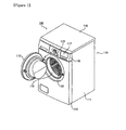
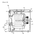
- FIG. 1 is a perspective view showing a washing machine 100 according to one exemplary embodiment of the present invention.
- FIG. 2 is a cross-sectional view taken along line II-II of FIG. 1 .
- the washing machine 100 includes: a cabinet 110 having an opening; a tub 121 disposed inside the cabinet 110 to store washing water supplied from an outside; a drum 122 disposed inside the tub 121 to receive laundry; a drive unit 130 for supplying a driving force to the drum 122; a washing water supply device (not shown) for supplying washing water from outside the cabinet 110; and a draining device (not indicated) for discharging the washing water in the drum 122 to the outside.
- the washing machine 100 may include an output unit (not shown) for informing a user on the outside of information.
- the output unit may include a sound output unit for informing the user on the outside of sound information and a display unit 117 for informing the user on the outside of picture information.
- the cabinet 110 includes a cabinet main body 111, a cover 112 disposed on a front surface of the cabinet main body 111 and having an opening portion, a top plate 115 disposed on an upper side of the cover 112 and coupled to the cabinet main body 111, and a control panel 116 disposed at one side of the top plate 115 and coupled to the cabinet main body 111.
- a door 113 rotatably coupled to the cover 12 is disposed on the cover 112 so as to open and close the opening portion.
- a gasket 119 coupled to one side of the cover 112 and coupled and fixed to the other side of the tub 121 is disposed at the opening portion. The gasket 119 can prevent the washing water from flowing into the tub when taking out wet laundry in the drum 122.
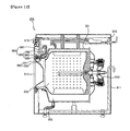
- the washing machine 100 includes a spray nozzle 190 disposed inside the cabinet to spray washing water into the drum 122 and a direction changing unit 180 for varying a spraying direction of the washing water sprayed from the spray nozzle into the drum.
- the spray nozzles 190 may be provided in plural number.
- the plurality of spray nozzles 190 include a first spray nozzle 191 disposed on the gasket 119 for spraying washing water in one direction and a second spray nozzle 192 disposed on the gasket 119 for spraying washing water in a different direction from that of the first spray nozzle 191.
- the first spray nozzle 191 and the second spray nozzle 192 may be formed at a predetermined angle so as to spray washing water in different directions from each other.
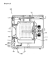
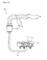
- FIG. 3 is a conceptual diagram showing the circulation and spraying of washing water of the washing machine 100 shown in FIG. 1 .
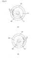
- FIG. 4 is a conceptual diagram showing the spray direction of the drum 122 shown in FIG. 3 and the spray direction of washing water.
- a user puts laundry in the drum 122 before operating the washing machine 100.
- washing water is introduced from outside.
- the washing water is introduced into the drum 122 and the tub 122 and stored therein.
- the drum 122 rotates.
- the rotation of the drum 122 may be done in various fashions. That is, the drum 122 can rotate simultaneously with the introduction of the washing water. Further, the drum 122 can rotate when the washing water being introduced reaches a predetermined water level.
- the following description will be given with respect to a case where the drum 122 rotates when the washing water reaches a predetermined water level.
- the washing machine 100 according to the present invention is not limited to the above case, but the drum 122 may be operated in various manners.
- the hydraulic pressure varying unit may include a circulation pump 185 for circulating the washing water of the tub 121.
- the supply path 181 guides the washing water stored in the tub 121 to the circulation pump 185, with one side coupled to the tub 121.
- the circulation pump 185 is disposed in the supply path 181 to make the washing water in the supply path 181 flow as described above.
- the washing water flowing through the supply path 181 is dispensed by a direction changer 186.
- the washing water dispensed by the direction changer186 is distributed to a plurality of guide passages 183 and 184 guide the washing water to a plurality of spray nozzles 190.
- the washing water flown to the plurality of spray nozzles 190 is sprayed into the drum 122 according to a rotating direction of the drum by the operation of the circulation pump 181. Also, the spraying direction of the washing water sprayed into the drum 122 is varied depending on the rotating direction of the drum 122.
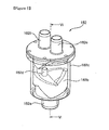
- FIG. 5 is a perspective view showing one exemplary embodiment of the direction changing unit 180 shown in FIG. 3 .
- FIG. 6 is a perspective view showing one exemplary embodiment of a dispenser 182 shown in FIG. 5 .
- FIG. 7 is a cross-sectional view taken along line VII-VII of FIG. 6 .
- the direction changing unit 180 includes a supply path 181 for guiding washing water from the tub 121, a hydraulic pressure varying unit (not shown) disposed in the supply path 181, for varying a hydraulic pressure of the washing water, and a direction changer 186 disposed between the hydraulic pressure varying unit and the plurality of spray nozzles 190, for varying a spraying direction in which the washing water flowing through the supply path 181 is sprayed into the drum 122.
- the hydraulic pressure varying unit may include a circulation pump 185.
- the hydraulic pressure varying unit according to the present invention is not limited to the circulation pump 185.
- the hydraulic pressure varying unit encompasses all devices, such as the circulation pump 185, capable of controlling the hydraulic pressure of the washing water flowing in the supply path 181.
- the hydraulic pressure varying unit is the circulation pump 185.
- the spray nozzles 190 may be formed in plurality.
- the plurality of spray nozzles 190 include the first spray nozzle 191 for spraying washing water in one direction and the second spray nozzle 192 for spraying washing water in a different direction from that of the first spray nozzle 191.
- the direction changer 186 includes a dispenser 182 which dispenses washing water to the plurality of spray nozzles 190 so as to vary the spraying direction of the washing water sprayed into the drum 122.
- the direction changer 186 includes a plurality of guide passages 183 and 184 for guiding the washing water dispensed from the dispenser 182 to the spray nozzles 190.
- the dispenser 182 includes a body portion 182c for introducing washing water and a switch unit 182b disposed inside the body portion 182c and selectively opening and closing the plurality of guide passages 183 and 184.
- the plurality of guide passages 183 and 184 include a first guide passage 183 coupled to the first spray nozzle 191 and a second guide passage 184 disposed at one side of the first guide passage 183 and coupled to the second spray nozzle 192.
- the dispenser 182 includes a position detecting unit 188 for detecting the position of the switch unit 182b.
- the position detecting unit 1880 includes a signal generator 188a disposed on the switch unit 182b for generating a signal to the outside and a signal detector 188b disposed at one side of the body portion 182c for detecting the signal generated from the signal generator 188a.
- the signal generator 188a may include a magnet for applying a magnetic field to the outside.
- the signal detector 188b may include a magnetic detector for detecting the magnetic field and detecting the position of the switch unit 182b.
- the position detecting unit 188 is not limited to as described above, but may be formed in various ways.
- the position detecting unit 188 includes every device capable of detecting the position of the switch unit 182b.
- the signal generator 188a and the signal detector 188b may be disposed at various positions. For the convenience of explanation, the following description will be made with respect to a case where the signal detector 188a is disposed at one side of the body portion 182c and the signal generator 188a is disposed at the switch unit 182b.
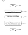
- FIG. 8 is a block diagram showing a control flow of the washing machine 100 shown in FIG. 1 .
- FIG. 9 is a perspective view showing one exemplary embodiment of a control sequence of the washing machine 100 shown in FIG. 1 .
- washing water is introduced into the drum 122 and the tub 122 by the operation of the washing machine 100.
- the drum 122 rotates.(S120)
- Laundry received in the drum 122 rotates along with the rotation of the drum 122.
- the direction changing unit 180 sprays the washing water into the drum 122 based on the rotation of the drum 122.
- the direction changing unit 180 varies the spraying direction of the washing water depending on the rotating direction of the drum 122.
- a rotation detecting unit 131 detects the rotating direction of the drum 122 while the drum 122 rotates. Also, the position detecting unit 188 detects the position of the switch unit 182b and transfers it to a control unit 170. (S130)
- the control unit 170 controls the switch unit 182b to open and close the first guide passage 191 or the second guide passage 192 based on the transferred position of the switch unit 182b.
- the signal detector 188a may be disposed at various positions of the body portion 182c.
- the signal detector 188a may be disposed at a portion where the first guide passage 183 and the second guide passage 184 are coupled.
- the following description will be given with respect to a case where the signal detector 188b is disposed at the portion where the first guide passage 183 and the second guide passage 184 are coupled.
- the control unit 170 determines whether or not the switch unit 182b closes the second guide passage 192b. If it is determined that the first guide passage 191 is opened and the second guide passage 192 is closed based on the position of the switch unit 182b, the control unit 170 operates the circulation pump 185 to circulate the washing water.
- the washing water flows through the supply path 181 and is supplied to the first guide passage 183 via the body portion 182c.
- the washing water supplied to the first guide passage 183 is sprayed into the drum 122 via the first spray nozzle 191.
- the washing water sprays the washing water onto the laundry of the drum 122. Therefore, it is possible to spray the washing water accurately onto the laundry of the drum 122 in accordance with the rotation of the drum 122.
- the switch unit 182b may be disposed at a lower side of the body portion 182c by its self-weight.
- a signal generated from the signal generator 188a disposed at the switch unit 182b is detected by the signal detector 188b.
- At least one signal detector 188b is disposed at one side of the body portion 182c as explained above.
- the signal detector 188b is unable to detect a signal if the switch unit 182b is disposed on the lower side. At this time, the control unit 170 operates the circulation pump 185.
- the switch unit 182b moves along with the washing water in the body portion 182c.
- the signal detector 188b transmits a signal to the control unit 170.
- the signal detector 182b When the circulation pump 185 operates and the switch unit 182b closes the second guide passage 184, the signal detector 182b does not transmit a signal to the control unit 170. On the other hand, when the switch unit 182b closes the first guide passage 183, the signal detector 182b transmits a signal to the control unit 170.
- control unit 170 If no signal is transmitted, the control unit 170 continuously operates the circulation pump 185. On the other hand, when a signal is transmitted, the control unit 170 stops the operation of the circulation pump 185.
- the switch unit 182b moves downward of the body portion 182c.
- the control unit 170 operates the circulation pump 185.
- the switch unit positioned on the lower side of the body portion 182c moves upward.
- the switch unit 182b opens the first guide passage 183. In addition, the switch unit 182b closes the second guide passage 184.
- the signal detector 188b When the signal detector 188b detects that the intensity of the signal emitted from the signal generator 188a exceeds a predetermined value, the signal detector 188b transmits the signal to the control unit 170.
- the control unit 170 determines that the switch unit 182b closes the first guide passage 183 based on the signal transmitted from the signal detector 188b.
- the control unit 170 temporarily stops the circulation pump 185.
- the control unit 170 controls such that the circulation pump 185 operates again after the elapse of a predetermined time.
- the switch unit 182b moves upward of the body portion while rotating.
- One side of the switch unit 182b is projected to close the portion coupled to the second guide passage 184.
- the signal detector 188b does not transmit a signal to the control unit 170 because the signal detector 188b is spaced a predetermined gap apart from the signal generator 188a. Therefore, when the drum 122 rotates clockwise by the operation of the circulation pump 185, washing water can be accurately sprayed onto the laundry of the drum 122.
- the signal detector 188b detects a signal generated from the signal generator 188a during the operation of the circulation pump 185, the signal is transmitted to the control unit 170.
- the control unit 170 controls such that the operation of the circulation pump 185 is not stopped but continues. As such, the circulation pump 185 continuously operates, and hence the washing water flows through the first guide passage 183 and is sprayed into the drum 122 via the first spray nozzle 191.
- the washing water is controlled so as to flow through the second guide passage 183 in the same or similar manner as described above.
- the rotation detecting unit 131 detects the rotation of the drum 122 and transmits it to the control unit 170.
- the control unit 170 determines whether or not the second guide passage 184 is opened based on the position of the switch unit 182b detected from the signal generator 188a.
- the signal detector 188b transmits the signal to the control unit 170 when the switch unit 182b closes the first guide passage 183.
- the control unit 170 determines whether or not the switch unit 182b closes the second guide passage 184. If it is determined that the switch unit 182b closes the first guide passage 183, the control unit 170 continuously operates the circulation pump 185 to circulate the washing water through the second guide passage 184.
- control unit 170 If it is determined that no signal is detected, the control unit 170 operates the circulation pump 185. Once the circulation pump 185 operates, the signal detector 188b detects a signal.
- the signal detector 188b transmits the signal to the control unit 170.
- the control unit 170 determines based on the signal that the switch unit 182b closes the first guide passage 183.
- the control unit 170 continuously operates the circulation pump 185.
- control unit 170 determines that the switch unit 182b closes the second guide passage 184.
- the control unit 170 controls such that the operation of the circulation pump 185 is stopped.
- the circulation pump 185 is temporarily stopped, a hydraulic pressure of the washing water in the body portion 182c diminishes. Accordingly, the switch unit 182b disposed inside the body portion 182c moves downward of the body portion 182c.
- the washing water flows again to the body portion 182c.
- the washing water flown to the body portion 182c applies a hydraulic pressure to the switch unit 182b, so that the switch unit 182b moves upward of the body portion 182c while rotating.
- the switch unit 182b closes the first guide passage 183 and opens the second guide passage 184. Accordingly, when the drum 122 rotates counterclockwise, the second guide passage 184 is opened and the washing water is sprayed onto the laundry of the drum 122.
- the output unit outputs a warning message to the user on the outside.
- the sound output unit outputs an alarm, a voice, a buzzer, etc. so that the user on the outside can recognize.
- the display unit 117 outputs a picture, text, etc. so that the user on the outside can recognize.
- the user is able to easily recognize from the outside the washing water sprayed in a direction different from the rotating direction.
- the washing water flowing through the first guide passage 183 is sprayed into the drum 122 via the first spray nozzle 191. Also, the washing water flowing through the second guide passage 184 is sprayed into the drum 122 via the second spray nozzle 192.
- the first spray nozzle 191 and the second spray nozzle 192 are disposed to form a predetermined angle.
- the first spray nozzle 191 sprays the washing water supplied from the first guide passage 183 in one direction of the drum 122.
- the second spray nozzle 192 sprays the washing water supplied from the second guide passage 184 in a different direction from the direction of spraying from the first spray nozzle 191.
- the first spray nozzle 191 sprays the washing water onto the laundry in the drum 122 when the drum 122 rotates clockwise.
- the second spray nozzle 192 sprays the washing water onto the laundry in the drum 122 when the drum 122 rotates counterclockwise.
- first spray nozzle 191 and the second spray nozzle 192 may be disposed at various positions.
- the first spray nozzle 191 and the second spray nozzle 192 may be disposed inside the cabinet 110 to spray the washing water into the drum 122.
- the first spray nozzle 191 and the second spray nozzle 192 may be disposed on the gasket 119 which is disposed between the cover 112 and the tub 121.
- the washing machine 100 is not limited to the above-described one, but is extended to the range in which a person skilled in the art could easily invent. Further, the foregoing exemplary embodiment is merely one implementation according to the present invention, the first spray nozzle 191 and the second spray nozzle 192 include all devices and methods that spray washing water directly into the drum 122 on the basis of the rotation of the drum 122.
- the signal detector 188b may be disposed in plurality at one side of the body portion 182c.
- the plurality of signal detectors 188b may include a first signal detector (not shown) disposed at a portion where the body portion 182c and the first guide passage 183 are coupled and a second signal detector (not shown) disposed at a portion where the body portion 182c and the second guide passage 183 are coupled.
- the washing water is supplied into the drum 122 in the same or similar manner as described above.
- the circulation pump 185 When the drum 122 rotates clockwise, the circulation pump 185 operates. Once the circulation pump 185 operates, the position detecting unit 188 detects the position of the switch unit 182b.
- the first signal detector or the second signal detector Based on a signal generated from the signal generator 188a disposed at the switch unit 182b, the first signal detector or the second signal detector detects the position of the switch 182b.
- the control unit 170 determines that the switch unit 182b closes the first guide passage 183.
- the control unit 170 controls the operation of the circulation pump 185 so that the switch unit 182b closes the second guide passage 184.
- the control unit 170 continuously operates the circulation pump 185.
- the washing water is sprayed into the drum 122 via the first guide passage 183 based on the rotation of the drum 122.
- the position detecting unit 188 detects the position of the switch unit 182b.
- the first signal detector or the second signal detector detects the position of the switch unit 182b.
- the control unit 170 determines that the switch unit 182b closes the first guide passage 183. Accordingly, the control unit 170 continuously operates the circulation pump 185.
- the control unit 170 determines that the switch unit 182b closes the second guide passage 184.
- the control unit 170 stops the operation of the circulation pump 185. After the elapse of a predetermined time, the control unit 170 operates the circulation pump 185 again. When the circulation pump 185 operates, the switch unit 182b moves upward of the body portion 182c by rotation.
- the switch unit 182c opens the second guide passage 184 and closes the first guide passage 183. Accordingly, when the drum 122 rotates counterclockwise, the washing water is sprayed through the second guide passage 184.
- control unit 170 operates the circulation pump 185.
- the switch unit 182b moves upward of the body portion 182c and closes either the first guide passage 182 or the second guide passage 184.
- the first signal detector or the second signal detector detects a signal and transmits it to the control unit 170.
- the control unit 170 determines that the switch unit 182b closes the first guide passage 183. Accordingly, the control unit 170 controls the circulation pump 185 in the same or similar manner as described above.
- the control unit 170 determines that the switch unit 182b closes the second guide passage 184. Accordingly, the control unit 170 controls the circulation pump 185 in the same or similar manner as described above.
- the washing machine 100 is able to spray washing water onto the laundry of the drum 122 based on the rotating direction of the drum 122. Also, since the washing water is sprayed onto spread laundry, the washing water can be rapidly supplied to the laundry.
- the output unit outputs a warning message to the user on the outside.
- the sound output unit outputs an alarm, a voice, a buzzer, etc. so that the user on the outside can recognize.
- the display unit 117 outputs a picture, text, etc. so that the user on the outside can recognize.
- the user is able to easily recognize from the outside the washing water sprayed in a direction different from the rotating direction.
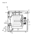
- FIG. 10 is a conceptual diagram showing a second exemplary embodiment in which the washing water of the washing machine 100 shown in FIG. 1 is circulated and sprayed.
- FIG. 11 is a conceptual diagram showing the spray direction of a drum 222 shown in FIG. 10 and the spray direction of washing water.
- FIG. 12 is a perspective view showing the direction changing unit 280 shown in FIG. 10 .
- the same reference numerals as those of the above-described exemplary embodiment will indicate the same members.
- the direction changing unit 280 varies the direction for spraying washing water into the drum based on the rotation of the drum 222. Therefore, the washing water can be accurately sprayed onto the laundry of the drum 222 in accordance with the rotation of the drum 222.
- the direction changing unit 280 may include a start-up motor 282 disposed at one side of the spray nozzle 291 to change the direction of the spray nozzle 291.
- the direction changing unit 280 may include a supply path 281 for guiding washing water from the tub 221, a hydraulic pressure varying unit 285 disposed in the supply path 281 for varying a hydraulic pressure of the washing water, and a start-up motor 282 for changing the spraying direction of the spray nozzle 291 by a varied hydraulic pressure.
- the hydraulic pressure varying unit 285 may include a circulation pump 285.
- the circulation pump 285 operates to circulate the washing water.
- the rotating detecting unit 131 detects the rotation of the drum 222. Based on the detected rotation, the control unit 170 controls the start-up motor 282 so as to spray the washing water onto the laundry of the drum 222.
- the control unit 17 actuates the start-up motor 282.
- the control unit 170 controls the start-up motor 282 such that the spray nozzle 291 is positioned in one direction.
- control unit 170 controls the start-up motor 282 such that the spray nozzle 291 is positioned in a different direction.
- the spray nozzle 291 sprays the washing water onto the laundry by the rotation of the drum 222. Accordingly, the washing water is accurately sprayed onto the laundry in accordance with the rotation of the drum 222. Moreover, because the washing water is rapidly supplied to the laundry, washing performance is improved and washing time is shortened.
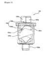
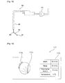
- FIG. 13 is a conceptual diagram showing a third exemplary embodiment in which the washing water of the washing machine 100 shown in FIG. 1 is circulated and sprayed.
- FIG. 14 is a conceptual diagram showing the spray direction of a drum 322 shown in FIG. 13 and the spray direction of washing water.
- FIG. 15 is a perspective view showing the direction changing unit 380 shown in FIG. 13 .
- the same reference numerals as those of the above-described exemplary embodiment will indicate the same members.
- the direction changing unit 380 may vary the spraying direction of the washing water supplied from an outside and sprayed into the drum 322.
- the direction changing unit 380 includes a supply path 381 for supplying washing water from the outside, a washing water supply device 325 for controlling a hydraulic pressure of the washing water in the supply path 381, and a direction changer 386 for varying the direction of spraying supplied washing water.
- the washing water supply device 325 may include a pump and a solenoid valve for controlling the supply path 381.
- the direction changing unit 386 includes a dispenser 382 for distributing supplied washing water.
- the dispenser 382 dispenses the washing water supplied from the outside to a plurality of guide passages 383 and 384.
- the dispenser 382 includes a body portion (not shown) for introducing washing water and a switch unit (not shown) disposed inside the body portion, for selectively opening and closing the plurality of guide passages 383 and 384.
- washing water is introduced.
- the dispenser 382 dispenses the washing water to the first guide passage 383 or the second guide passage 384.
- the dispenser 382 dispenses the washing water by a hydraulic pressure as described above.
- the washing water supply device 325 varies the hydraulic pressure of the washing water flowing through the supply path 381. If the washing water supply device 325 includes the pump, the control unit 170 controls the hydraulic pressure of the washing water by operating the pump. The control unit 170 can control the hydraulic pressure of the washing water by applying electric current to the solenoid valve for a predetermined time.
- control unit 170 controls the washing water supply device 325 in accordance with a rotating direction of the drum 322.
- the control unit 170 controls in the same or similar manner as described in FIGS. 5 to 9 on the basis of the rotating direction of the drum 322.
- washing water is sprayed via the first spray nozzle 291.
- the washing machine 100 is able to spray the washing water on the basis of the rotation of the drum 322. Since the washing water is sprayed in accordance with the rotation of the drum 322, the washing water can be supplied accurately and rapidly onto the laundry.
- the output unit outputs a warning message to the user on the outside.
- the sound output unit outputs an alarm, a voice, a buzzer, etc. so that the user on the outside can recognize.
- the display unit 117 outputs a picture, text, etc. so that the user on the outside can recognize.
- the user is able to easily recognize from the outside the washing water sprayed in a direction different from the rotating direction.
- FIG. 16 is a conceptual diagram showing a fourth exemplary embodiment in which the washing water of the washing machine 100 shown in FIG. 1 is circulated and sprayed.
- FIG. 17 is a conceptual diagram showing the spray direction of a drum 422 shown in FIG. 16 and the spray direction of washing water.
- FIG. 18 is a perspective view showing the direction changing unit 480 shown in FIG. 16 .
- the same reference numerals as those of the above-described exemplary embodiment will indicate the same members.
- the direction changing unit 480 may spray the washing water supplied from an outside on the basis of the rotation of the drum 422.
- the direction changing unit 480 sprays washing water onto the laundry of the drum 422 when the drum 422 rotates.
- the direction changing unit 480 includes a supply path 481 for supplying washing water from the outside and a washing water supply device 425 for controlling the washing water in the supply path 481. Further, the direction changing unit 480 may include a start-up motor 482 disposed at one side of the spray nozzle 491 to vary the direction of the spray nozzle 491.
- washing water is supplied from the outside.
- the rotation detecting unit 131 detects the rotation of the drum 422 and transmits it to the control unit 170.
- the control unit 170 controls the start-up motor 482 on the basis of the rotation of the drum 422.
- the start-up motor 482 varies the direction of the spray nozzle 491 on the basis of the rotation of the drum 422.
- the start-up motor 482 varies the direction of the spray nozzle 491 so as to spray the washing water onto the laundry in the drum 422.
- the spray nozzle sprays washing water in one direction.
- the washing water can be accurately sprayed on the laundry of the drum 422.
- the spray nozzle sprays washing water in another direction different from the one direction shown in FIG. 17A .
- the washing water can be accurately sprayed on the laundry of the drum 422.
- control unit 170 controls the start-up motor 491 in the same or similar manner as described in FIGS. 10 to 12 .
- the washing water spraying direction of the spray nozzle 291 is varied depending on the rotation of the drum 422.
- the washing water sprayed from the spray nozzle 491 is accurately and rapidly sprayed onto the laundry of the drum 422.
- FIG. 19 is a perspective view showing one exemplary embodiment of a display unit 117 shown in FIG. 1 .
- the user can input an external signal through an input unit 118 so as to control the circulation pump 185.
- an input unit 118 so as to control the circulation pump 185.
- washing water is sprayed into the drum 122 in the same or similar manner as described above.
- the user can control through the input unit 118 such that the washing water is sprayed according to a motion of the drum 122. That is, the user can input the external signal through the input unit 118 such that the washing water is sprayed differently according to whether the drum 122 rapidly rotates once or reciprocates.
- the method of controlling washing water is carried out in the same or similar manner as described above.
- a display unit 117 displays a motion of the drum 122 and a washing water spray model.
- the drum 122 carries out its motion in various directions according to each cycle. While the motion is being performed, the display unit 117 displays the motion of the drum 122 through a motion display portion 117a corresponding to the motion. The motion may be variously displayed as a rotating direction, a rotational speed, and so on.
- a washing water spray display portion 117b for showing a direction of spraying washing water to the drum 122 is displayed on one side of the motion display portion 117a. That is, as explained above, the washing water spraying direction depending on the rotating direction of the drum 122 is displayed on the display unit 117 according to the external signal input by the user. Accordingly, the user can easily check the washing water spraying direction depending on the rotation of the drum 122 and the motion of the drum 122.
Description
- The present invention relates to a washing machine, and more particularly, to a washing machine which sprays washing water in a drum.
- Generally, a washing machine refers to an apparatus for washing or drying laundry. The washing machine provides convenience to users by treating laundry. Especially, the washing machine has to treat laundry by effectively using washing water when washing laundry.
-
EP 1 696 066 A2 relates to a washing machine and a washing method, in which waste of washing water is reduced and washing efficiency is improved, wherein a nozzle assembly is provided at an upper portion of a gasket to pass through the gasket and includes a first nozzle connected with a circulating hose to spray washing water pumped by a circulating pump into the tub and a second nozzle connected with a supply hose to spray steam generated by a steam generator or washing water passing through the steam generator into the tub. - An object of the present invention is to provide a washing machine and washing method which improves washing performance by spraying washing water onto laundry.
- The present invention provides a washing machine according to claim 1.
-
-
FIG. 1 is a perspective view showing a washing machine according to one exemplary embodiment of the present invention; -
FIG. 2 is a cross-sectional view taken along line II-II ofFIG. 1 ; -
FIG. 3 is a conceptual diagram showing the circulation and spraying of washing water of the washing machine shown inFIG. 1 ; -
FIG. 4A is a conceptual diagram showing the spray direction of washing water according to clockwise rotation of the drum shown inFIG 3 ; -
FIG. 4B is a conceptual diagram showing the spray direction of washing water according to counterclockwise rotation of the drum shown inFIG 3 ; -
FIG. 5 is a perspective view showing one exemplary embodiment of a direction changing unit shown inFIG. 3 ; -
FIG. 6 is a perspective view showing one exemplary embodiment of a dispenser shown inFIG. 5 ; -
FIG. 7 is a cross-sectional view taken along line VII-VII ofFIG. 6 ; -
FIG. 8 is a block diagram showing a control flow of the washing machine shown inFIG. 1 ; -
FIG. 9 is a perspective view showing one exemplary embodiment of a control sequence of the washing machine shown inFIG. 1 . -
FIG. 10 is a conceptual diagram showing a second exemplary embodiment in which the washing water of the washing machine shown inFIG. 1 is circulated and sprayed; -
FIG. 11A is a conceptual diagram showing the spray direction of washing water according to clockwise rotation of the drum shown inFIG 10 ; -
FIG. 11B is a conceptual diagram showing the spray direction of washing water according to counterclockwise rotation of the drum shown inFIG 10 ; -
FIG. 12 is a perspective view showing the direction changing unit shown inFIG. 10 ; -
FIG. 13 is a conceptual diagram showing a third exemplary embodiment in which the washing water of the washing machine shown inFIG. 1 is circulated and sprayed; -
FIG. 14A is a conceptual diagram showing the spray direction of washing water according to clockwise rotation of the drum shown inFIG 13 ; -
FIG. 14B is a conceptual diagram showing the spray direction of washing water according to counterclockwise rotation of the drum shown inFIG 13 ; -
FIG. 15 is a perspective view showing the direction changing unit shown inFIG. 13 ; -
FIG. 16 is a conceptual diagram showing a fourth exemplary embodiment in which the washing water of the washing machine shown inFIG. 1 is circulated and sprayed; -
FIG. 17A is a conceptual diagram showing the spray direction of washing water according to clockwise rotation of the drum shown inFIG 16 ; -
FIG. 17B is a conceptual diagram showing the spray direction of washing water according to counterclockwise rotation of the drum shown inFIG 16 ; -
FIG. 18 is a perspective view showing the direction changing unit shown inFIG. 16 ; and -
FIG. 19 is a perspective view showing one exemplary embodiment of a display unit shown inFIG. 1 . - Hereinafter, a laundry treatment operation of the
washing machine 100 will be described focused on a laundry washing cycle for the convenience of explanation. However, thewashing machine 100 according to the present invention is not limited to the following description, but encompasses all cases where washing water is sprayed and soaked into laundry in the laundry treatment operation of thewashing machine 100. For example, the present invention can be applied to all of a cycle for rinsing laundry with washing water containing no detergent, a cycle for dehydrating laundry, and a cycle for dehydrating laundry by dry air, as well as the cycle for washing laundry. -
FIG. 1 is a perspective view showing awashing machine 100 according to one exemplary embodiment of the present invention.FIG. 2 is a cross-sectional view taken along line II-II ofFIG. 1 . - Referring to
FIGS. 1 to 2 , thewashing machine 100 includes: acabinet 110 having an opening; atub 121 disposed inside thecabinet 110 to store washing water supplied from an outside; adrum 122 disposed inside thetub 121 to receive laundry; adrive unit 130 for supplying a driving force to thedrum 122; a washing water supply device (not shown) for supplying washing water from outside thecabinet 110; and a draining device (not indicated) for discharging the washing water in thedrum 122 to the outside. - The
washing machine 100 may include an output unit (not shown) for informing a user on the outside of information. The output unit may include a sound output unit for informing the user on the outside of sound information and adisplay unit 117 for informing the user on the outside of picture information. - The
cabinet 110 includes a cabinetmain body 111, acover 112 disposed on a front surface of the cabinetmain body 111 and having an opening portion, atop plate 115 disposed on an upper side of thecover 112 and coupled to the cabinetmain body 111, and acontrol panel 116 disposed at one side of thetop plate 115 and coupled to the cabinetmain body 111. - In addition, a
door 113 rotatably coupled to the cover 12 is disposed on thecover 112 so as to open and close the opening portion. Also, agasket 119 coupled to one side of thecover 112 and coupled and fixed to the other side of thetub 121 is disposed at the opening portion. Thegasket 119 can prevent the washing water from flowing into the tub when taking out wet laundry in thedrum 122. - Further, the
washing machine 100 includes aspray nozzle 190 disposed inside the cabinet to spray washing water into thedrum 122 and adirection changing unit 180 for varying a spraying direction of the washing water sprayed from the spray nozzle into the drum. - The
spray nozzles 190 may be provided in plural number. The plurality ofspray nozzles 190 include afirst spray nozzle 191 disposed on thegasket 119 for spraying washing water in one direction and asecond spray nozzle 192 disposed on thegasket 119 for spraying washing water in a different direction from that of thefirst spray nozzle 191. Thefirst spray nozzle 191 and thesecond spray nozzle 192 may be formed at a predetermined angle so as to spray washing water in different directions from each other. - The following description will be given with respect to a method of spraying washing water to the
drum 122 and the aforementioned devices. -
FIG. 3 is a conceptual diagram showing the circulation and spraying of washing water of thewashing machine 100 shown inFIG. 1 .FIG. 4 is a conceptual diagram showing the spray direction of thedrum 122 shown inFIG. 3 and the spray direction of washing water. - Referring to
FIG. 3 to 4 , a user puts laundry in thedrum 122 before operating thewashing machine 100. When the user operates thewashing machine 100, washing water is introduced from outside. When the washing water is introduced, the washing water is introduced into thedrum 122 and thetub 122 and stored therein. - As the washing water is introduced, the
drum 122 rotates. The rotation of thedrum 122 may be done in various fashions. That is, thedrum 122 can rotate simultaneously with the introduction of the washing water. Further, thedrum 122 can rotate when the washing water being introduced reaches a predetermined water level. The following description will be given with respect to a case where thedrum 122 rotates when the washing water reaches a predetermined water level. Thewashing machine 100 according to the present invention is not limited to the above case, but thedrum 122 may be operated in various manners. - When the
drum 122 rotates, the laundry received in thedrum 122 rotates along with thedrum 122. At this time, a hydraulic pressure varying unit (not shown) is operated to circulate the washing water stored in thetub 121. The hydraulic pressure varying unit may include acirculation pump 185 for circulating the washing water of thetub 121. - When the
circulation pump 185 operates, the washing water flows through asupply path 181. Thesupply path 181 guides the washing water stored in thetub 121 to thecirculation pump 185, with one side coupled to thetub 121. - The
circulation pump 185 is disposed in thesupply path 181 to make the washing water in thesupply path 181 flow as described above. The washing water flowing through thesupply path 181 is dispensed by adirection changer 186. - The washing water dispensed by the direction changer186 is distributed to a plurality of
guide passages spray nozzles 190. - The washing water flown to the plurality of
spray nozzles 190 is sprayed into thedrum 122 according to a rotating direction of the drum by the operation of thecirculation pump 181. Also, the spraying direction of the washing water sprayed into thedrum 122 is varied depending on the rotating direction of thedrum 122. - Referring to
FIG. 4A , when thedrum 122 rotates clockwise, the washing water is sprayed from afirst spray nozzle 191. - Referring to
FIG. 4B , when thedrum 122 rotates counterclockwise, the washing water is sprayed from asecond spray nozzle 192. - A method and apparatus for spraying washing water will be described hereinafter in detail.
-
FIG. 5 is a perspective view showing one exemplary embodiment of thedirection changing unit 180 shown inFIG. 3 .FIG. 6 is a perspective view showing one exemplary embodiment of adispenser 182 shown inFIG. 5 .FIG. 7 is a cross-sectional view taken along line VII-VII ofFIG. 6 . - Referring to
FIGS. 5 to 7 , thedirection changing unit 180 includes asupply path 181 for guiding washing water from thetub 121, a hydraulic pressure varying unit (not shown) disposed in thesupply path 181, for varying a hydraulic pressure of the washing water, and adirection changer 186 disposed between the hydraulic pressure varying unit and the plurality ofspray nozzles 190, for varying a spraying direction in which the washing water flowing through thesupply path 181 is sprayed into thedrum 122. Meanwhile, the hydraulic pressure varying unit may include acirculation pump 185. - The hydraulic pressure varying unit according to the present invention is not limited to the
circulation pump 185. The hydraulic pressure varying unit encompasses all devices, such as thecirculation pump 185, capable of controlling the hydraulic pressure of the washing water flowing in thesupply path 181. For the convenience of explanation, the following description will be given with respect to a case where the hydraulic pressure varying unit is thecirculation pump 185. - The
spray nozzles 190 may be formed in plurality. The plurality ofspray nozzles 190 include thefirst spray nozzle 191 for spraying washing water in one direction and thesecond spray nozzle 192 for spraying washing water in a different direction from that of thefirst spray nozzle 191. - The
direction changer 186 includes adispenser 182 which dispenses washing water to the plurality ofspray nozzles 190 so as to vary the spraying direction of the washing water sprayed into thedrum 122. Thedirection changer 186 includes a plurality ofguide passages dispenser 182 to thespray nozzles 190. - Further, the
dispenser 182 includes abody portion 182c for introducing washing water and aswitch unit 182b disposed inside thebody portion 182c and selectively opening and closing the plurality ofguide passages - The plurality of
guide passages first guide passage 183 coupled to thefirst spray nozzle 191 and asecond guide passage 184 disposed at one side of thefirst guide passage 183 and coupled to thesecond spray nozzle 192. - The
dispenser 182 includes aposition detecting unit 188 for detecting the position of theswitch unit 182b. The position detecting unit 1880 includes asignal generator 188a disposed on theswitch unit 182b for generating a signal to the outside and asignal detector 188b disposed at one side of thebody portion 182c for detecting the signal generated from thesignal generator 188a. - The
signal generator 188a may include a magnet for applying a magnetic field to the outside. In addition, thesignal detector 188b may include a magnetic detector for detecting the magnetic field and detecting the position of theswitch unit 182b. - The
position detecting unit 188 is not limited to as described above, but may be formed in various ways. Theposition detecting unit 188 includes every device capable of detecting the position of theswitch unit 182b. - Also, the
signal generator 188a and thesignal detector 188b may be disposed at various positions. For the convenience of explanation, the following description will be made with respect to a case where thesignal detector 188a is disposed at one side of thebody portion 182c and thesignal generator 188a is disposed at theswitch unit 182b. -
FIG. 8 is a block diagram showing a control flow of thewashing machine 100 shown inFIG. 1 .FIG. 9 is a perspective view showing one exemplary embodiment of a control sequence of thewashing machine 100 shown inFIG. 1 . - Referring to
FIGS. 8 and9 , washing water is introduced into thedrum 122 and thetub 122 by the operation of thewashing machine 100. When the washing machine in thetub 121 reaches a predetermined water level, thedrum 122 rotates.(S120) - Laundry received in the
drum 122 rotates along with the rotation of thedrum 122. Thedirection changing unit 180 sprays the washing water into thedrum 122 based on the rotation of thedrum 122. Thedirection changing unit 180 varies the spraying direction of the washing water depending on the rotating direction of thedrum 122. - A
rotation detecting unit 131 detects the rotating direction of thedrum 122 while thedrum 122 rotates. Also, theposition detecting unit 188 detects the position of theswitch unit 182b and transfers it to acontrol unit 170. (S130) - The
control unit 170 controls theswitch unit 182b to open and close thefirst guide passage 191 or thesecond guide passage 192 based on the transferred position of the switch unit 182b.(S140) - The
signal detector 188a may be disposed at various positions of thebody portion 182c. Thesignal detector 188a may be disposed at a portion where thefirst guide passage 183 and thesecond guide passage 184 are coupled. The following description will be given with respect to a case where thesignal detector 188b is disposed at the portion where thefirst guide passage 183 and thesecond guide passage 184 are coupled. - For example, if it is determined that the
drum 122 rotates clockwise, thecontrol unit 170 determines whether or not theswitch unit 182b closes the second guide passage 192b. If it is determined that thefirst guide passage 191 is opened and thesecond guide passage 192 is closed based on the position of theswitch unit 182b, thecontrol unit 170 operates thecirculation pump 185 to circulate the washing water. - When the
circulation pump 185 operates, the washing water flows through thesupply path 181 and is supplied to thefirst guide passage 183 via thebody portion 182c. The washing water supplied to thefirst guide passage 183 is sprayed into thedrum 122 via thefirst spray nozzle 191. The washing water sprays the washing water onto the laundry of thedrum 122. Therefore, it is possible to spray the washing water accurately onto the laundry of thedrum 122 in accordance with the rotation of thedrum 122. - Meanwhile, the
switch unit 182b may be disposed at a lower side of thebody portion 182c by its self-weight. A signal generated from thesignal generator 188a disposed at theswitch unit 182b is detected by thesignal detector 188b. At least onesignal detector 188b is disposed at one side of thebody portion 182c as explained above. - The
signal detector 188b is unable to detect a signal if theswitch unit 182b is disposed on the lower side. At this time, thecontrol unit 170 operates thecirculation pump 185. - When the
circulation pump 185 operates, theswitch unit 182b moves along with the washing water in thebody portion 182c. When theswitch unit 182b moves upward of thebody portion 182c, thesignal detector 188b transmits a signal to thecontrol unit 170. - When the
circulation pump 185 operates and theswitch unit 182b closes thesecond guide passage 184, thesignal detector 182b does not transmit a signal to thecontrol unit 170. On the other hand, when theswitch unit 182b closes thefirst guide passage 183, thesignal detector 182b transmits a signal to thecontrol unit 170. - If no signal is transmitted, the
control unit 170 continuously operates thecirculation pump 185. On the other hand, when a signal is transmitted, thecontrol unit 170 stops the operation of thecirculation pump 185. - When the operation of the
circulation pump 185 is stopped, theswitch unit 182b moves downward of thebody portion 182c. After the elapse of a predetermined time, thecontrol unit 170 operates thecirculation pump 185. Once thecirculation pump 185 operates, the switch unit positioned on the lower side of thebody portion 182c moves upward. - At this time, the
switch unit 182b opens thefirst guide passage 183. In addition, theswitch unit 182b closes thesecond guide passage 184. - When the
signal detector 188b detects that the intensity of the signal emitted from thesignal generator 188a exceeds a predetermined value, thesignal detector 188b transmits the signal to thecontrol unit 170. - The
control unit 170 determines that theswitch unit 182b closes thefirst guide passage 183 based on the signal transmitted from thesignal detector 188b. - If it is determined that the
switch unit 182b closes thefirst guide passage 183 when thedrum 122 rotates clockwise as above, thecontrol unit 170 temporarily stops thecirculation pump 185. - When the
circulation pump 185 is stopped, theswitch unit 182b moves downward of thebody portion 182c by its self-weight. - The
control unit 170 controls such that thecirculation pump 185 operates again after the elapse of a predetermined time. When thecirculation pump 185 operates, theswitch unit 182b moves upward of the body portion while rotating. One side of theswitch unit 182b is projected to close the portion coupled to thesecond guide passage 184. - When the
switch unit 182b closes thesecond guide passage 184, thesignal detector 188b does not transmit a signal to thecontrol unit 170 because thesignal detector 188b is spaced a predetermined gap apart from thesignal generator 188a. Therefore, when thedrum 122 rotates clockwise by the operation of thecirculation pump 185, washing water can be accurately sprayed onto the laundry of thedrum 122. - Meanwhile, when the
signal detector 188b detects a signal generated from thesignal generator 188a during the operation of thecirculation pump 185, the signal is transmitted to thecontrol unit 170. - Once the signal is transmitted from the
signal detector 188b to thecontrol unit 170, thecontrol unit 170 controls such that the operation of thecirculation pump 185 is not stopped but continues. As such, thecirculation pump 185 continuously operates, and hence the washing water flows through thefirst guide passage 183 and is sprayed into thedrum 122 via thefirst spray nozzle 191. - On the other hand, when the
drum 122 rotates counterclockwise, the washing water is controlled so as to flow through thesecond guide passage 183 in the same or similar manner as described above. - When the
drum 122 rotates counterclockwise, therotation detecting unit 131 detects the rotation of thedrum 122 and transmits it to thecontrol unit 170. - The
control unit 170 determines whether or not thesecond guide passage 184 is opened based on the position of theswitch unit 182b detected from thesignal generator 188a. Thesignal detector 188b transmits the signal to thecontrol unit 170 when theswitch unit 182b closes thefirst guide passage 183. - Based on the transmitted signal, the
control unit 170 determines whether or not theswitch unit 182b closes thesecond guide passage 184. If it is determined that theswitch unit 182b closes thefirst guide passage 183, thecontrol unit 170 continuously operates thecirculation pump 185 to circulate the washing water through thesecond guide passage 184. - If it is determined that no signal is detected, the
control unit 170 operates thecirculation pump 185. Once thecirculation pump 185 operates, thesignal detector 188b detects a signal. - When a signal is detected, the
signal detector 188b transmits the signal to thecontrol unit 170. Thecontrol unit 170 determines based on the signal that theswitch unit 182b closes thefirst guide passage 183. - If it is determined that the
switch unit 182b closes thefirst guide passage 183, thecontrol unit 170 continuously operates thecirculation pump 185. - On the other hand, if the signal is not continuously detected, the
control unit 170 determines that theswitch unit 182b closes thesecond guide passage 184. - If it is determined that the
switch unit 182b closes thesecond guide passage 184, thecontrol unit 170 controls such that the operation of thecirculation pump 185 is stopped. When thecirculation pump 185 is temporarily stopped, a hydraulic pressure of the washing water in thebody portion 182c diminishes. Accordingly, theswitch unit 182b disposed inside thebody portion 182c moves downward of thebody portion 182c. - After the elapse of a predetermined time, when the
control unit 170 controls thecirculation pump 185 to be operated, the washing water flows again to thebody portion 182c. At this time, the washing water flown to thebody portion 182c applies a hydraulic pressure to theswitch unit 182b, so that theswitch unit 182b moves upward of thebody portion 182c while rotating. - The
switch unit 182b closes thefirst guide passage 183 and opens thesecond guide passage 184. Accordingly, when thedrum 122 rotates counterclockwise, thesecond guide passage 184 is opened and the washing water is sprayed onto the laundry of thedrum 122. - Meanwhile, if the rotation direction and the spraying direction are different from each other as seen from above, the output unit outputs a warning message to the user on the outside.
- The sound output unit outputs an alarm, a voice, a buzzer, etc. so that the user on the outside can recognize.
- The
display unit 117 outputs a picture, text, etc. so that the user on the outside can recognize. - Accordingly, the user is able to easily recognize from the outside the washing water sprayed in a direction different from the rotating direction.
- The washing water flowing through the
first guide passage 183 is sprayed into thedrum 122 via thefirst spray nozzle 191. Also, the washing water flowing through thesecond guide passage 184 is sprayed into thedrum 122 via thesecond spray nozzle 192. - At this time, the
first spray nozzle 191 and thesecond spray nozzle 192 are disposed to form a predetermined angle. Thefirst spray nozzle 191 sprays the washing water supplied from thefirst guide passage 183 in one direction of thedrum 122. Also, thesecond spray nozzle 192 sprays the washing water supplied from thesecond guide passage 184 in a different direction from the direction of spraying from thefirst spray nozzle 191. - For example, the
first spray nozzle 191 sprays the washing water onto the laundry in thedrum 122 when thedrum 122 rotates clockwise. Also, thesecond spray nozzle 192 sprays the washing water onto the laundry in thedrum 122 when thedrum 122 rotates counterclockwise. - In addition, the
first spray nozzle 191 and thesecond spray nozzle 192 may be disposed at various positions. Thefirst spray nozzle 191 and thesecond spray nozzle 192 may be disposed inside thecabinet 110 to spray the washing water into thedrum 122. Thefirst spray nozzle 191 and thesecond spray nozzle 192 may be disposed on thegasket 119 which is disposed between thecover 112 and thetub 121. - The
washing machine 100 according to the present invention is not limited to the above-described one, but is extended to the range in which a person skilled in the art could easily invent. Further, the foregoing exemplary embodiment is merely one implementation according to the present invention, thefirst spray nozzle 191 and thesecond spray nozzle 192 include all devices and methods that spray washing water directly into thedrum 122 on the basis of the rotation of thedrum 122. - The
signal detector 188b may be disposed in plurality at one side of thebody portion 182c. - The plurality of
signal detectors 188b may include a first signal detector (not shown) disposed at a portion where thebody portion 182c and thefirst guide passage 183 are coupled and a second signal detector (not shown) disposed at a portion where thebody portion 182c and thesecond guide passage 183 are coupled. - In a case where the
signal detector 188b is disposed in plurality at one side of thebody portion 182c, the washing water is supplied into thedrum 122 in the same or similar manner as described above. - For example, when the
drum 122 rotates clockwise, thecirculation pump 185 operates. Once thecirculation pump 185 operates, theposition detecting unit 188 detects the position of theswitch unit 182b. - Based on a signal generated from the
signal generator 188a disposed at theswitch unit 182b, the first signal detector or the second signal detector detects the position of theswitch 182b. - When the first signal detector detects the signal of the
switch unit 182b, thecontrol unit 170 determines that theswitch unit 182b closes thefirst guide passage 183. Thecontrol unit 170 controls the operation of thecirculation pump 185 so that theswitch unit 182b closes thesecond guide passage 184. - If it is determined that the
switch unit 182b closes thesecond guide passage 184, thecontrol unit 170 continuously operates thecirculation pump 185. Thus, the washing water is sprayed into thedrum 122 via thefirst guide passage 183 based on the rotation of thedrum 122. - When the
drum 122 rotates counterclockwise, theposition detecting unit 188 detects the position of theswitch unit 182b. Here, the first signal detector or the second signal detector detects the position of theswitch unit 182b. - When the first signal detector detects a signal, the
control unit 170 determines that theswitch unit 182b closes thefirst guide passage 183. Accordingly, thecontrol unit 170 continuously operates thecirculation pump 185. - On the other hand, when the second signal detector detects a signal, the
control unit 170 determines that theswitch unit 182b closes thesecond guide passage 184. - The
control unit 170 stops the operation of thecirculation pump 185. After the elapse of a predetermined time, thecontrol unit 170 operates thecirculation pump 185 again. When thecirculation pump 185 operates, theswitch unit 182b moves upward of thebody portion 182c by rotation. - The
switch unit 182c opens thesecond guide passage 184 and closes thefirst guide passage 183. Accordingly, when thedrum 122 rotates counterclockwise, the washing water is sprayed through thesecond guide passage 184. - Meanwhile, in a case where the
switch unit 182b is disposed on the lower side of thebody portion 182c, no signal is detected. Here, thecontrol unit 170 operates thecirculation pump 185. - The
switch unit 182b moves upward of thebody portion 182c and closes either thefirst guide passage 182 or thesecond guide passage 184. The first signal detector or the second signal detector detects a signal and transmits it to thecontrol unit 170. - When the first signal detector detects a signal, the
control unit 170 determines that theswitch unit 182b closes thefirst guide passage 183. Accordingly, thecontrol unit 170 controls thecirculation pump 185 in the same or similar manner as described above. - When the second signal detector detects a signal, the
control unit 170 determines that theswitch unit 182b closes thesecond guide passage 184. Accordingly, thecontrol unit 170 controls thecirculation pump 185 in the same or similar manner as described above. - Accordingly, the
washing machine 100 according to the present invention is able to spray washing water onto the laundry of thedrum 122 based on the rotating direction of thedrum 122. Also, since the washing water is sprayed onto spread laundry, the washing water can be rapidly supplied to the laundry. - Meanwhile, if the rotation direction and the spraying direction are different from each other as seen from above, the output unit outputs a warning message to the user on the outside.
- The sound output unit outputs an alarm, a voice, a buzzer, etc. so that the user on the outside can recognize.
- The
display unit 117 outputs a picture, text, etc. so that the user on the outside can recognize. - Accordingly, the user is able to easily recognize from the outside the washing water sprayed in a direction different from the rotating direction.
-
FIG. 10 is a conceptual diagram showing a second exemplary embodiment in which the washing water of thewashing machine 100 shown inFIG. 1 is circulated and sprayed.FIG. 11 is a conceptual diagram showing the spray direction of adrum 222 shown inFIG. 10 and the spray direction of washing water.FIG. 12 is a perspective view showing thedirection changing unit 280 shown inFIG. 10 . In the following, the same reference numerals as those of the above-described exemplary embodiment will indicate the same members. - Referring to
FIGS. 10 and12 , thedirection changing unit 280 varies the direction for spraying washing water into the drum based on the rotation of thedrum 222. Therefore, the washing water can be accurately sprayed onto the laundry of thedrum 222 in accordance with the rotation of thedrum 222. - The
direction changing unit 280 may include a start-upmotor 282 disposed at one side of thespray nozzle 291 to change the direction of thespray nozzle 291. - The
direction changing unit 280 may include asupply path 281 for guiding washing water from thetub 221, a hydraulicpressure varying unit 285 disposed in thesupply path 281 for varying a hydraulic pressure of the washing water, and a start-upmotor 282 for changing the spraying direction of thespray nozzle 291 by a varied hydraulic pressure. The hydraulicpressure varying unit 285 may include acirculation pump 285. - When the
drum 122 rotates as described above, thecirculation pump 285 operates to circulate the washing water. - Referring to
FIG. 11 , when thedrum 122 rotates, the rotating detectingunit 131 detects the rotation of thedrum 222. Based on the detected rotation, thecontrol unit 170 controls the start-upmotor 282 so as to spray the washing water onto the laundry of thedrum 222. - Referring to
FIG. 11A , when thedrum 222 rotates, the control unit 17 actuates the start-upmotor 282. When thedrum 222 rotates clockwise, thecontrol unit 170 controls the start-upmotor 282 such that thespray nozzle 291 is positioned in one direction. - Referring to
FIG. 11B , when thedrum 222 rotates counterclockwise, thecontrol unit 170 controls the start-upmotor 282 such that thespray nozzle 291 is positioned in a different direction. - The
spray nozzle 291 sprays the washing water onto the laundry by the rotation of thedrum 222. Accordingly, the washing water is accurately sprayed onto the laundry in accordance with the rotation of thedrum 222. Moreover, because the washing water is rapidly supplied to the laundry, washing performance is improved and washing time is shortened. -
FIG. 13 is a conceptual diagram showing a third exemplary embodiment in which the washing water of thewashing machine 100 shown inFIG. 1 is circulated and sprayed.FIG. 14 is a conceptual diagram showing the spray direction of adrum 322 shown inFIG. 13 and the spray direction of washing water.FIG. 15 is a perspective view showing thedirection changing unit 380 shown inFIG. 13 . In the following, the same reference numerals as those of the above-described exemplary embodiment will indicate the same members. - Referring to
FIGS. 13 and15 , thedirection changing unit 380 may vary the spraying direction of the washing water supplied from an outside and sprayed into thedrum 322. - The
direction changing unit 380 includes asupply path 381 for supplying washing water from the outside, a washingwater supply device 325 for controlling a hydraulic pressure of the washing water in thesupply path 381, and a direction changer 386 for varying the direction of spraying supplied washing water. - The washing
water supply device 325 may include a pump and a solenoid valve for controlling thesupply path 381. - The direction changing unit 386 includes a
dispenser 382 for distributing supplied washing water. Thedispenser 382 dispenses the washing water supplied from the outside to a plurality ofguide passages - The
dispenser 382 includes a body portion (not shown) for introducing washing water and a switch unit (not shown) disposed inside the body portion, for selectively opening and closing the plurality ofguide passages - When the
washing machine 300 operates, washing water is introduced. Thedispenser 382 dispenses the washing water to thefirst guide passage 383 or thesecond guide passage 384. Thedispenser 382 dispenses the washing water by a hydraulic pressure as described above. - The washing
water supply device 325 varies the hydraulic pressure of the washing water flowing through thesupply path 381. If the washingwater supply device 325 includes the pump, thecontrol unit 170 controls the hydraulic pressure of the washing water by operating the pump. Thecontrol unit 170 can control the hydraulic pressure of the washing water by applying electric current to the solenoid valve for a predetermined time. - Referring to
FIG. 14 , thecontrol unit 170 controls the washingwater supply device 325 in accordance with a rotating direction of thedrum 322. Thecontrol unit 170 controls in the same or similar manner as described inFIGS. 5 to 9 on the basis of the rotating direction of thedrum 322. - Referring to
FIG. 14A , when thedrum 322 rotates clockwise, washing water is sprayed via thefirst spray nozzle 291. - Referring to
FIG. 14B , when thedrum 322 rotates counterclockwise, the washing water is sprayed via thesecond spray nozzle 392. - Accordingly, the
washing machine 100 is able to spray the washing water on the basis of the rotation of thedrum 322. Since the washing water is sprayed in accordance with the rotation of thedrum 322, the washing water can be supplied accurately and rapidly onto the laundry. - Meanwhile, if the rotation direction and the spraying direction are different from each other as seen from above, the output unit outputs a warning message to the user on the outside.
- The sound output unit outputs an alarm, a voice, a buzzer, etc. so that the user on the outside can recognize.
- The
display unit 117 outputs a picture, text, etc. so that the user on the outside can recognize. - Accordingly, the user is able to easily recognize from the outside the washing water sprayed in a direction different from the rotating direction.
-
FIG. 16 is a conceptual diagram showing a fourth exemplary embodiment in which the washing water of thewashing machine 100 shown inFIG. 1 is circulated and sprayed.FIG. 17 is a conceptual diagram showing the spray direction of adrum 422 shown inFIG. 16 and the spray direction of washing water.FIG. 18 is a perspective view showing thedirection changing unit 480 shown inFIG. 16 . In the following description, the same reference numerals as those of the above-described exemplary embodiment will indicate the same members. - Referring to
FIGS. 16 and18 , thedirection changing unit 480 may spray the washing water supplied from an outside on the basis of the rotation of thedrum 422. Thedirection changing unit 480 sprays washing water onto the laundry of thedrum 422 when thedrum 422 rotates. - The
direction changing unit 480 includes asupply path 481 for supplying washing water from the outside and a washingwater supply device 425 for controlling the washing water in thesupply path 481. Further, thedirection changing unit 480 may include a start-upmotor 482 disposed at one side of thespray nozzle 491 to vary the direction of thespray nozzle 491. - When the
washing machine 400 operates, washing water is supplied from the outside. Once the washing water is supplied, therotation detecting unit 131 detects the rotation of thedrum 422 and transmits it to thecontrol unit 170. Thecontrol unit 170 controls the start-upmotor 482 on the basis of the rotation of thedrum 422. - Referring to
FIG. 17 , the start-upmotor 482 varies the direction of thespray nozzle 491 on the basis of the rotation of thedrum 422. The start-upmotor 482 varies the direction of thespray nozzle 491 so as to spray the washing water onto the laundry in thedrum 422. - Referring to
FIG. 17A , when thedrum 422 rotates clockwise, the spray nozzle sprays washing water in one direction. Thus, the washing water can be accurately sprayed on the laundry of thedrum 422. - Referring to
FIG. 17B , when thedrum 422 rotates counterclockwise, the spray nozzle sprays washing water in another direction different from the one direction shown inFIG. 17A . Thus, the washing water can be accurately sprayed on the laundry of thedrum 422. - When the
drum 422 rotates, thecontrol unit 170 controls the start-upmotor 491 in the same or similar manner as described inFIGS. 10 to 12 . - Accordingly, the washing water spraying direction of the
spray nozzle 291 is varied depending on the rotation of thedrum 422. The washing water sprayed from thespray nozzle 491 is accurately and rapidly sprayed onto the laundry of thedrum 422. -
FIG. 19 is a perspective view showing one exemplary embodiment of adisplay unit 117 shown inFIG. 1 . - Referring to
FIG. 19 , the user can input an external signal through aninput unit 118 so as to control thecirculation pump 185. When the external signal is input, washing water is sprayed into thedrum 122 in the same or similar manner as described above. - The user can control through the
input unit 118 such that the washing water is sprayed according to a motion of thedrum 122. That is, the user can input the external signal through theinput unit 118 such that the washing water is sprayed differently according to whether thedrum 122 rapidly rotates once or reciprocates. The method of controlling washing water is carried out in the same or similar manner as described above. - When a user inputs the external signal to spray the washing water onto one side of the
drum 122, adisplay unit 117 displays a motion of thedrum 122 and a washing water spray model. - The
drum 122 carries out its motion in various directions according to each cycle. While the motion is being performed, thedisplay unit 117 displays the motion of thedrum 122 through amotion display portion 117a corresponding to the motion. The motion may be variously displayed as a rotating direction, a rotational speed, and so on. - In the
display unit 117, a washing waterspray display portion 117b for showing a direction of spraying washing water to thedrum 122 is displayed on one side of themotion display portion 117a. That is, as explained above, the washing water spraying direction depending on the rotating direction of thedrum 122 is displayed on thedisplay unit 117 according to the external signal input by the user. Accordingly, the user can easily check the washing water spraying direction depending on the rotation of thedrum 122 and the motion of thedrum 122.
Claims (7)
- A washing machine (100), comprising:a cabinet (110) having an opening;a drum (122) receiving laundry; anda plurality of spray nozzles (190) disposed inside the cabinet (110) to spray washing water into the drum (122); anda gasket (119) coupled to the opening,wherein the plurality of spray nozzles (190) is coupled to one side of the gasket (119),characterized by the plurality of spray nozzles (190) comprising:a first spray nozzle (191) disposed on the gasket (119) for spraying washing water in one direction; anda second spray nozzle (192) disposed on the gasket (119) for spraying washing water in a different direction from that of the first spray nozzle (191),wherein the first spray nozzle (191) and the second spray nozzle (192) form a predetermined angle.
- The washing machine (100) of claim 1, wherein the plurality of spray nozzles (190) sprays washing water onto the laundry.
- The washing machine (100) of claim 1, wherein the washing machine (100) further comprises a circulation pump (185) for circulating the washing water of the tub (121) to spray the washing water through the plurality of spray nozzles (190).
- The washing machine (100) of claim 1, wherein the washing machine (100) further comprises a washing water supply device for supplying washing water from outside the cabinet (110) to spray the washing water through the plurality of spray nozzles (190).
- The washing machine (100) of claim 1, wherein the plurality of spray nozzles (190) is disposed on a lower side of the gasket (119).
- The washing machine (100) of claim 1, wherein the plurality of spray nozzles (190) sprays washing water when the washing cycle of the laundry is performed.
- The washing machine (100) of claim 1, wherein the plurality of spray nozzles (190) sprays washing water when the rinsing cycle of the laundry is performed.
Priority Applications (2)
| Application Number | Priority Date | Filing Date | Title |
|---|---|---|---|
| PL09840092T PL2396464T3 (en) | 2009-02-16 | 2009-09-24 | Washing machine and washing method |
| EP13150985.3A EP2584084B1 (en) | 2009-02-16 | 2009-09-24 | Washing machine and washing method |
Applications Claiming Priority (3)
| Application Number | Priority Date | Filing Date | Title |
|---|---|---|---|
| KR20090012520 | 2009-02-16 | ||
| KR1020090071696A KR101590371B1 (en) | 2009-02-16 | 2009-08-04 | Washing machine and washing method |
| PCT/KR2009/005469 WO2010093102A1 (en) | 2009-02-16 | 2009-09-24 | Washing machine and washing method |
Related Child Applications (2)
| Application Number | Title | Priority Date | Filing Date |
|---|---|---|---|
| EP13150985.3A Division-Into EP2584084B1 (en) | 2009-02-16 | 2009-09-24 | Washing machine and washing method |
| EP13150985.3A Division EP2584084B1 (en) | 2009-02-16 | 2009-09-24 | Washing machine and washing method |
Publications (3)
| Publication Number | Publication Date |
|---|---|
| EP2396464A1 EP2396464A1 (en) | 2011-12-21 |
| EP2396464A4 EP2396464A4 (en) | 2013-04-10 |
| EP2396464B1 true EP2396464B1 (en) | 2014-08-27 |
Family
ID=42558607
Family Applications (2)
| Application Number | Title | Priority Date | Filing Date |
|---|---|---|---|
| EP13150985.3A Active EP2584084B1 (en) | 2009-02-16 | 2009-09-24 | Washing machine and washing method |
| EP09840092.2A Active EP2396464B1 (en) | 2009-02-16 | 2009-09-24 | Washing machine and washing method |
Family Applications Before (1)
| Application Number | Title | Priority Date | Filing Date |
|---|---|---|---|
| EP13150985.3A Active EP2584084B1 (en) | 2009-02-16 | 2009-09-24 | Washing machine and washing method |
Country Status (11)
| Country | Link |
|---|---|
| US (1) | US8464560B2 (en) |
| EP (2) | EP2584084B1 (en) |
| JP (1) | JP2012517854A (en) |
| KR (1) | KR101590371B1 (en) |
| CN (2) | CN103173965B (en) |
| AU (1) | AU2009340125B2 (en) |
| ES (1) | ES2519516T3 (en) |
| MX (1) | MX341406B (en) |
| PL (1) | PL2396464T3 (en) |
| RU (1) | RU2480545C1 (en) |
| WO (1) | WO2010093102A1 (en) |
Families Citing this family (39)
| Publication number | Priority date | Publication date | Assignee | Title |
|---|---|---|---|---|
| US20100024137A1 (en) * | 2008-08-01 | 2010-02-04 | Myong Hum Im | Washing machine and washing method therefor |
| US8763184B2 (en) * | 2008-08-01 | 2014-07-01 | Lg Electronics Inc. | Control method of a laundry machine |
| US8713736B2 (en) | 2008-08-01 | 2014-05-06 | Lg Electronics Inc. | Control method of a laundry machine |
| US9416478B2 (en) * | 2009-03-31 | 2016-08-16 | Lg Electronics Inc. | Washing machine and washing method |
| US8966944B2 (en) | 2008-08-01 | 2015-03-03 | Lg Electronics Inc. | Control method of a laundry machine |
| KR20100028920A (en) * | 2008-09-05 | 2010-03-15 | 엘지전자 주식회사 | Method for washing and washing machine |
| US8746015B2 (en) * | 2008-08-01 | 2014-06-10 | Lg Electronics Inc. | Laundry machine |
| AU2010214203B2 (en) | 2009-02-11 | 2013-08-22 | Lg Electronics Inc. | Washing method and washing machine |
| AU2010201327B2 (en) * | 2009-04-03 | 2011-11-03 | Lg Electronics Inc. | Washing machine |
| US9822473B2 (en) * | 2009-07-27 | 2017-11-21 | Lg Electronics Inc. | Control method of a laundry machine |
| US9695537B2 (en) * | 2009-07-27 | 2017-07-04 | Lg Electronics Inc. | Control method of a laundry machine |
| US10533275B2 (en) * | 2009-07-27 | 2020-01-14 | Lg Electronics Inc. | Control method of a laundry machine |
| US9234307B2 (en) * | 2009-07-27 | 2016-01-12 | Lg Electronics Inc. | Control method of a laundry machine |
| US8776297B2 (en) | 2009-10-13 | 2014-07-15 | Lg Electronics Inc. | Laundry treating apparatus and method |
| US9045853B2 (en) * | 2009-10-13 | 2015-06-02 | Lg Electronics Inc. | Laundry treating apparatus |
| EP2631349B1 (en) * | 2010-01-08 | 2017-04-26 | Panasonic Corporation | Washing machine |
| US8850856B2 (en) * | 2010-12-16 | 2014-10-07 | General Electric Company | Apparatus and method for using a dispensing system utilizing a Venturi component |
| JP5828123B2 (en) * | 2011-02-23 | 2015-12-02 | パナソニックIpマネジメント株式会社 | Drum washing machine |
| US9051676B2 (en) | 2011-03-30 | 2015-06-09 | General Electric Company | Apparatus and method for utilizing a venturi effect in a dispenser |
| ES2598836T3 (en) * | 2011-04-14 | 2017-01-30 | Lg Electronics Inc. | Washing procedure |
| FR2980217B1 (en) * | 2011-09-15 | 2014-05-16 | Fagorbrandt Sas | WASHING MACHINE COMPRISING A WATER RECIRCULATION DEVICE |
| DE102013100908A1 (en) * | 2013-01-30 | 2014-07-31 | Miele & Cie. Kg | Method of operating a washing machine with a circulating device and a washing machine |
| CN104074023B (en) * | 2013-03-25 | 2017-11-28 | 海尔集团技术研发中心 | Washing machine and control method for washing |
| KR102227372B1 (en) * | 2014-04-21 | 2021-03-11 | 엘지전자 주식회사 | Laundry washing method |
| JP6019416B2 (en) * | 2015-02-03 | 2016-11-02 | パナソニックIpマネジメント株式会社 | Drum washing machine |
| KR102378129B1 (en) * | 2015-04-27 | 2022-03-24 | 엘지전자 주식회사 | Laundry Treating Apparatus |
| KR102512212B1 (en) * | 2016-02-23 | 2023-03-22 | 삼성전자주식회사 | Washing apparatus, and control method for the same |
| WO2018135019A1 (en) * | 2017-01-19 | 2018-07-26 | シャープ株式会社 | Fabric treatment device |
| KR102477943B1 (en) * | 2017-03-08 | 2022-12-14 | 엘지전자 주식회사 | Method for controlling washing machine |
| PL3755835T3 (en) | 2018-02-22 | 2024-02-19 | Electrolux Appliances Aktiebolag | Laundry washing machine equipped with a liquid supply line |
| CN110387713A (en) * | 2018-04-16 | 2019-10-29 | 青岛海尔滚筒洗衣机有限公司 | Roller washing machine and its spray system |
| CN110607662A (en) * | 2018-06-15 | 2019-12-24 | 青岛海尔滚筒洗衣机有限公司 | Roller washing machine and spraying system thereof |
| US11208750B2 (en) | 2018-12-29 | 2021-12-28 | Whirlpool Corporation | Laundry appliance with a deflector |
| IT201900001815A1 (en) * | 2019-02-08 | 2020-08-08 | Candy Spa | Washing machine |
| CN111764113A (en) * | 2019-03-12 | 2020-10-13 | 青岛海尔滚筒洗衣机有限公司 | Atomization module for drum washing machine, drum washing machine and control method |
| US11761134B2 (en) | 2019-05-23 | 2023-09-19 | Whirlpool Corporation | Laundry appliance |
| CN117888337A (en) | 2019-05-23 | 2024-04-16 | 惠而浦公司 | Laundry appliance |
| US11377772B2 (en) | 2019-05-23 | 2022-07-05 | Whirlpool Corporation | Laundry appliance |
| KR20220077432A (en) * | 2020-12-02 | 2022-06-09 | 엘지전자 주식회사 | Landaury treating apparatus |
Family Cites Families (17)
| Publication number | Priority date | Publication date | Assignee | Title |
|---|---|---|---|---|
| US3387310A (en) * | 1966-09-22 | 1968-06-11 | Donald E. Marshall | Washing apparatus and method |
| US5150588A (en) * | 1990-12-28 | 1992-09-29 | Whirlpool Co | Concentrate wash automatic washer with reciprocating basket |
| US5307651A (en) * | 1993-05-19 | 1994-05-03 | William Felzer | Washing machine |
| KR100517619B1 (en) * | 2003-04-25 | 2005-09-28 | 엘지전자 주식회사 | Circulation apparatus of drum washer |
| KR100505255B1 (en) * | 2003-05-02 | 2005-08-02 | 엘지전자 주식회사 | A water level sensing method of drum washer |
| CN1566495A (en) * | 2003-06-17 | 2005-01-19 | 乐金电子(天津)电器有限公司 | Drainage direction adjustable washing machine |
| EP1616990B1 (en) * | 2004-07-13 | 2017-08-30 | LG Electronics, Inc. | Washing machine with steam generation apparatus |
| KR20060055222A (en) * | 2004-11-18 | 2006-05-23 | 삼성전자주식회사 | Washing machine and control method thereof |
| KR100698147B1 (en) * | 2005-02-25 | 2007-03-26 | 엘지전자 주식회사 | Control Method for Washing Machine |
| JP2006239141A (en) * | 2005-03-03 | 2006-09-14 | Sharp Corp | Drum type washing machine |
| JP2007054416A (en) | 2005-08-25 | 2007-03-08 | Sharp Corp | Drum type washing machine |
| KR101146275B1 (en) * | 2005-12-16 | 2012-05-16 | 주식회사 대우일렉트로닉스 | Circulation apparatus for drum type washing machine |
| JP4972369B2 (en) * | 2006-09-20 | 2012-07-11 | 日立アプライアンス株式会社 | Drum washing machine |
| CN201023074Y (en) * | 2006-11-17 | 2008-02-20 | 李嘉宁 | Shower nozzle |
| JP4697184B2 (en) * | 2007-05-25 | 2011-06-08 | パナソニック株式会社 | dishwasher |
| JP5106206B2 (en) * | 2008-03-28 | 2012-12-26 | 京セラSlcテクノロジー株式会社 | Insulating sheet punching method and wiring board manufacturing method |
| ES2755887T3 (en) | 2009-08-11 | 2020-04-24 | Lg Electronics Inc | Laundry machine |
-
2009
- 2009-08-04 KR KR1020090071696A patent/KR101590371B1/en active IP Right Grant
- 2009-09-24 CN CN201310091044.5A patent/CN103173965B/en active Active
- 2009-09-24 EP EP13150985.3A patent/EP2584084B1/en active Active
- 2009-09-24 WO PCT/KR2009/005469 patent/WO2010093102A1/en active Application Filing
- 2009-09-24 ES ES09840092.2T patent/ES2519516T3/en active Active
- 2009-09-24 CN CN2009801579235A patent/CN102341540A/en active Pending
- 2009-09-24 MX MX2011008704A patent/MX341406B/en active IP Right Grant
- 2009-09-24 RU RU2011138012/12A patent/RU2480545C1/en active
- 2009-09-24 JP JP2011550045A patent/JP2012517854A/en active Pending
- 2009-09-24 PL PL09840092T patent/PL2396464T3/en unknown
- 2009-09-24 AU AU2009340125A patent/AU2009340125B2/en active Active
- 2009-09-24 EP EP09840092.2A patent/EP2396464B1/en active Active
-
2010
- 2010-02-12 US US12/704,923 patent/US8464560B2/en active Active
Also Published As
| Publication number | Publication date |
|---|---|
| JP2012517854A (en) | 2012-08-09 |
| US20100205753A1 (en) | 2010-08-19 |
| CN103173965B (en) | 2015-08-12 |
| KR101590371B1 (en) | 2016-02-02 |
| KR20100093455A (en) | 2010-08-25 |
| AU2009340125B2 (en) | 2014-05-29 |
| ES2519516T3 (en) | 2014-11-07 |
| EP2396464A4 (en) | 2013-04-10 |
| CN103173965A (en) | 2013-06-26 |
| MX2011008704A (en) | 2015-04-10 |
| EP2584084B1 (en) | 2014-12-10 |
| EP2396464A1 (en) | 2011-12-21 |
| RU2480545C1 (en) | 2013-04-27 |
| PL2396464T3 (en) | 2015-02-27 |
| EP2584084A1 (en) | 2013-04-24 |
| US8464560B2 (en) | 2013-06-18 |
| CN102341540A (en) | 2012-02-01 |
| AU2009340125A1 (en) | 2011-09-15 |
| MX341406B (en) | 2016-08-19 |
| WO2010093102A1 (en) | 2010-08-19 |
Similar Documents
| Publication | Publication Date | Title |
|---|---|---|
| EP2396464B1 (en) | Washing machine and washing method | |
| EP2602381B1 (en) | Drum washing machine and washing method thereof | |
| CN107109761B (en) | Washing machine | |
| EP2516714B1 (en) | Washing method and washing machine | |
| EP1851374B1 (en) | Method for washing a tub or a drum in a washing machine | |
| EP2818591B1 (en) | Laundry treating appliance and method of operation for a laundry treating appliance | |
| JP2006141985A (en) | Washing machine and its control method | |
| JP2008206966A (en) | Washer and its control method | |
| KR20180072336A (en) | Washing machine and Controlling method for the same | |
| CN112210965B (en) | Laundry treatment apparatus with treatment chemical dispenser | |
| JPH1099584A (en) | Washing machine with centrifugal pump | |
| KR102487868B1 (en) | Washing machine and Controlling method for the same | |
| KR20110072974A (en) | Method for washing and washing machine | |
| AU2014218442B2 (en) | Washing machine and washing method | |
| KR20110053081A (en) | Method for washing and washing machine | |
| EP3315651A1 (en) | Dispenser for a laundry treating household appliance having a float diverter | |
| JP5198621B2 (en) | Washing machine | |
| EP3323926B1 (en) | Laundry treating appliance and dispenser | |
| KR20110072977A (en) | Method for washing and washing machine | |
| WO2020020268A1 (en) | Top-loading washing machine | |
| KR20130122152A (en) | Washing machine and control method for the same | |
| KR20110072976A (en) | Method for washing and washing machine | |
| KR20060024578A (en) | Control method of washing machine/dryer | |
| KR20110074100A (en) | Method for washing and washing machine | |
| KR19990035356A (en) | Water splashing device and method of washing machine |
Legal Events
| Date | Code | Title | Description |
|---|---|---|---|
| PUAI | Public reference made under article 153(3) epc to a published international application that has entered the european phase |
Free format text: ORIGINAL CODE: 0009012 |
|
| 17P | Request for examination filed |
Effective date: 20110907 |
|
| AK | Designated contracting states |
Kind code of ref document: A1 Designated state(s): AT BE BG CH CY CZ DE DK EE ES FI FR GB GR HR HU IE IS IT LI LT LU LV MC MK MT NL NO PL PT RO SE SI SK SM TR |
|
| DAX | Request for extension of the european patent (deleted) | ||
| A4 | Supplementary search report drawn up and despatched |
Effective date: 20130312 |
|
| RIC1 | Information provided on ipc code assigned before grant |
Ipc: D06F 39/12 20060101ALI20130306BHEP Ipc: D06F 37/04 20060101ALI20130306BHEP Ipc: D06F 39/08 20060101AFI20130306BHEP |
|
| GRAP | Despatch of communication of intention to grant a patent |
Free format text: ORIGINAL CODE: EPIDOSNIGR1 |
|
| INTG | Intention to grant announced |
Effective date: 20140124 |
|
| GRAP | Despatch of communication of intention to grant a patent |
Free format text: ORIGINAL CODE: EPIDOSNIGR1 |
|
| INTG | Intention to grant announced |
Effective date: 20140331 |
|
| GRAS | Grant fee paid |
Free format text: ORIGINAL CODE: EPIDOSNIGR3 |
|
| GRAA | (expected) grant |
Free format text: ORIGINAL CODE: 0009210 |
|
| AK | Designated contracting states |
Kind code of ref document: B1 Designated state(s): AT BE BG CH CY CZ DE DK EE ES FI FR GB GR HR HU IE IS IT LI LT LU LV MC MK MT NL NO PL PT RO SE SI SK SM TR |
|
| REG | Reference to a national code |
Ref country code: GB Ref legal event code: FG4D |
|
| REG | Reference to a national code |
Ref country code: CH Ref legal event code: EP |
|
| REG | Reference to a national code |
Ref country code: AT Ref legal event code: REF Ref document number: 684603 Country of ref document: AT Kind code of ref document: T Effective date: 20140915 |
|
| REG | Reference to a national code |
Ref country code: IE Ref legal event code: FG4D |
|
| REG | Reference to a national code |
Ref country code: DE Ref legal event code: R096 Ref document number: 602009026357 Country of ref document: DE Effective date: 20141002 |
|
| REG | Reference to a national code |
Ref country code: NL Ref legal event code: T3 |
|
| REG | Reference to a national code |
Ref country code: ES Ref legal event code: FG2A Ref document number: 2519516 Country of ref document: ES Kind code of ref document: T3 Effective date: 20141107 |
|
| REG | Reference to a national code |
Ref country code: AT Ref legal event code: MK05 Ref document number: 684603 Country of ref document: AT Kind code of ref document: T Effective date: 20140827 |
|
| REG | Reference to a national code |
Ref country code: LT Ref legal event code: MG4D |
|
| PG25 | Lapsed in a contracting state [announced via postgrant information from national office to epo] |
Ref country code: NO Free format text: LAPSE BECAUSE OF FAILURE TO SUBMIT A TRANSLATION OF THE DESCRIPTION OR TO PAY THE FEE WITHIN THE PRESCRIBED TIME-LIMIT Effective date: 20141127 Ref country code: SE Free format text: LAPSE BECAUSE OF FAILURE TO SUBMIT A TRANSLATION OF THE DESCRIPTION OR TO PAY THE FEE WITHIN THE PRESCRIBED TIME-LIMIT Effective date: 20140827 Ref country code: BG Free format text: LAPSE BECAUSE OF FAILURE TO SUBMIT A TRANSLATION OF THE DESCRIPTION OR TO PAY THE FEE WITHIN THE PRESCRIBED TIME-LIMIT Effective date: 20141127 Ref country code: FI Free format text: LAPSE BECAUSE OF FAILURE TO SUBMIT A TRANSLATION OF THE DESCRIPTION OR TO PAY THE FEE WITHIN THE PRESCRIBED TIME-LIMIT Effective date: 20140827 Ref country code: LT Free format text: LAPSE BECAUSE OF FAILURE TO SUBMIT A TRANSLATION OF THE DESCRIPTION OR TO PAY THE FEE WITHIN THE PRESCRIBED TIME-LIMIT Effective date: 20140827 Ref country code: GR Free format text: LAPSE BECAUSE OF FAILURE TO SUBMIT A TRANSLATION OF THE DESCRIPTION OR TO PAY THE FEE WITHIN THE PRESCRIBED TIME-LIMIT Effective date: 20141128 Ref country code: PT Free format text: LAPSE BECAUSE OF FAILURE TO SUBMIT A TRANSLATION OF THE DESCRIPTION OR TO PAY THE FEE WITHIN THE PRESCRIBED TIME-LIMIT Effective date: 20141229 |
|
| PG25 | Lapsed in a contracting state [announced via postgrant information from national office to epo] |
Ref country code: LV Free format text: LAPSE BECAUSE OF FAILURE TO SUBMIT A TRANSLATION OF THE DESCRIPTION OR TO PAY THE FEE WITHIN THE PRESCRIBED TIME-LIMIT Effective date: 20140827 Ref country code: CY Free format text: LAPSE BECAUSE OF FAILURE TO SUBMIT A TRANSLATION OF THE DESCRIPTION OR TO PAY THE FEE WITHIN THE PRESCRIBED TIME-LIMIT Effective date: 20140827 Ref country code: HR Free format text: LAPSE BECAUSE OF FAILURE TO SUBMIT A TRANSLATION OF THE DESCRIPTION OR TO PAY THE FEE WITHIN THE PRESCRIBED TIME-LIMIT Effective date: 20140827 Ref country code: IS Free format text: LAPSE BECAUSE OF FAILURE TO SUBMIT A TRANSLATION OF THE DESCRIPTION OR TO PAY THE FEE WITHIN THE PRESCRIBED TIME-LIMIT Effective date: 20141227 Ref country code: AT Free format text: LAPSE BECAUSE OF FAILURE TO SUBMIT A TRANSLATION OF THE DESCRIPTION OR TO PAY THE FEE WITHIN THE PRESCRIBED TIME-LIMIT Effective date: 20140827 |
|
| REG | Reference to a national code |
Ref country code: PL Ref legal event code: T3 |
|
| PG25 | Lapsed in a contracting state [announced via postgrant information from national office to epo] |
Ref country code: EE Free format text: LAPSE BECAUSE OF FAILURE TO SUBMIT A TRANSLATION OF THE DESCRIPTION OR TO PAY THE FEE WITHIN THE PRESCRIBED TIME-LIMIT Effective date: 20140827 Ref country code: RO Free format text: LAPSE BECAUSE OF FAILURE TO SUBMIT A TRANSLATION OF THE DESCRIPTION OR TO PAY THE FEE WITHIN THE PRESCRIBED TIME-LIMIT Effective date: 20140827 Ref country code: CZ Free format text: LAPSE BECAUSE OF FAILURE TO SUBMIT A TRANSLATION OF THE DESCRIPTION OR TO PAY THE FEE WITHIN THE PRESCRIBED TIME-LIMIT Effective date: 20140827 Ref country code: DK Free format text: LAPSE BECAUSE OF FAILURE TO SUBMIT A TRANSLATION OF THE DESCRIPTION OR TO PAY THE FEE WITHIN THE PRESCRIBED TIME-LIMIT Effective date: 20140827 Ref country code: SK Free format text: LAPSE BECAUSE OF FAILURE TO SUBMIT A TRANSLATION OF THE DESCRIPTION OR TO PAY THE FEE WITHIN THE PRESCRIBED TIME-LIMIT Effective date: 20140827 |
|
| REG | Reference to a national code |
Ref country code: CH Ref legal event code: PL |
|
| REG | Reference to a national code |
Ref country code: DE Ref legal event code: R097 Ref document number: 602009026357 Country of ref document: DE |
|
| PG25 | Lapsed in a contracting state [announced via postgrant information from national office to epo] |
Ref country code: MC Free format text: LAPSE BECAUSE OF FAILURE TO SUBMIT A TRANSLATION OF THE DESCRIPTION OR TO PAY THE FEE WITHIN THE PRESCRIBED TIME-LIMIT Effective date: 20140827 |
|
| REG | Reference to a national code |
Ref country code: IE Ref legal event code: MM4A |
|
| PG25 | Lapsed in a contracting state [announced via postgrant information from national office to epo] |
Ref country code: BE Free format text: LAPSE BECAUSE OF NON-PAYMENT OF DUE FEES Effective date: 20140930 |
|
| PLBE | No opposition filed within time limit |
Free format text: ORIGINAL CODE: 0009261 |
|
| STAA | Information on the status of an ep patent application or granted ep patent |
Free format text: STATUS: NO OPPOSITION FILED WITHIN TIME LIMIT |
|
| PG25 | Lapsed in a contracting state [announced via postgrant information from national office to epo] |
Ref country code: CH Free format text: LAPSE BECAUSE OF NON-PAYMENT OF DUE FEES Effective date: 20140930 Ref country code: LI Free format text: LAPSE BECAUSE OF NON-PAYMENT OF DUE FEES Effective date: 20140930 |
|
| 26N | No opposition filed |
Effective date: 20150528 |
|
| PG25 | Lapsed in a contracting state [announced via postgrant information from national office to epo] |
Ref country code: IE Free format text: LAPSE BECAUSE OF NON-PAYMENT OF DUE FEES Effective date: 20140924 |
|
| PG25 | Lapsed in a contracting state [announced via postgrant information from national office to epo] |
Ref country code: SI Free format text: LAPSE BECAUSE OF FAILURE TO SUBMIT A TRANSLATION OF THE DESCRIPTION OR TO PAY THE FEE WITHIN THE PRESCRIBED TIME-LIMIT Effective date: 20140827 |
|
| PG25 | Lapsed in a contracting state [announced via postgrant information from national office to epo] |
Ref country code: SM Free format text: LAPSE BECAUSE OF FAILURE TO SUBMIT A TRANSLATION OF THE DESCRIPTION OR TO PAY THE FEE WITHIN THE PRESCRIBED TIME-LIMIT Effective date: 20140827 |
|
| PG25 | Lapsed in a contracting state [announced via postgrant information from national office to epo] |
Ref country code: MT Free format text: LAPSE BECAUSE OF FAILURE TO SUBMIT A TRANSLATION OF THE DESCRIPTION OR TO PAY THE FEE WITHIN THE PRESCRIBED TIME-LIMIT Effective date: 20140827 |
|
| PG25 | Lapsed in a contracting state [announced via postgrant information from national office to epo] |
Ref country code: LU Free format text: LAPSE BECAUSE OF NON-PAYMENT OF DUE FEES Effective date: 20140924 Ref country code: BE Free format text: LAPSE BECAUSE OF FAILURE TO SUBMIT A TRANSLATION OF THE DESCRIPTION OR TO PAY THE FEE WITHIN THE PRESCRIBED TIME-LIMIT Effective date: 20140827 Ref country code: HU Free format text: LAPSE BECAUSE OF FAILURE TO SUBMIT A TRANSLATION OF THE DESCRIPTION OR TO PAY THE FEE WITHIN THE PRESCRIBED TIME-LIMIT; INVALID AB INITIO Effective date: 20090924 |
|
| REG | Reference to a national code |
Ref country code: FR Ref legal event code: PLFP Year of fee payment: 8 |
|
| REG | Reference to a national code |
Ref country code: FR Ref legal event code: PLFP Year of fee payment: 9 |
|
| PG25 | Lapsed in a contracting state [announced via postgrant information from national office to epo] |
Ref country code: MK Free format text: LAPSE BECAUSE OF FAILURE TO SUBMIT A TRANSLATION OF THE DESCRIPTION OR TO PAY THE FEE WITHIN THE PRESCRIBED TIME-LIMIT Effective date: 20140827 |
|
| REG | Reference to a national code |
Ref country code: FR Ref legal event code: PLFP Year of fee payment: 10 |
|
| PGFP | Annual fee paid to national office [announced via postgrant information from national office to epo] |
Ref country code: GB Payment date: 20180807 Year of fee payment: 10 Ref country code: PL Payment date: 20180807 Year of fee payment: 10 |
|
| PGFP | Annual fee paid to national office [announced via postgrant information from national office to epo] |
Ref country code: ES Payment date: 20181009 Year of fee payment: 10 |
|
| GBPC | Gb: european patent ceased through non-payment of renewal fee |
Effective date: 20190924 |
|
| PG25 | Lapsed in a contracting state [announced via postgrant information from national office to epo] |
Ref country code: GB Free format text: LAPSE BECAUSE OF NON-PAYMENT OF DUE FEES Effective date: 20190924 |
|
| REG | Reference to a national code |
Ref country code: ES Ref legal event code: FD2A Effective date: 20210129 |
|
| PG25 | Lapsed in a contracting state [announced via postgrant information from national office to epo] |
Ref country code: ES Free format text: LAPSE BECAUSE OF NON-PAYMENT OF DUE FEES Effective date: 20190925 |
|
| PG25 | Lapsed in a contracting state [announced via postgrant information from national office to epo] |
Ref country code: PL Free format text: LAPSE BECAUSE OF NON-PAYMENT OF DUE FEES Effective date: 20190924 |
|
| PGFP | Annual fee paid to national office [announced via postgrant information from national office to epo] |
Ref country code: NL Payment date: 20220805 Year of fee payment: 14 |
|
| PGFP | Annual fee paid to national office [announced via postgrant information from national office to epo] |
Ref country code: TR Payment date: 20220808 Year of fee payment: 14 |
|
| PGFP | Annual fee paid to national office [announced via postgrant information from national office to epo] |
Ref country code: FR Payment date: 20220805 Year of fee payment: 14 |
|
| P01 | Opt-out of the competence of the unified patent court (upc) registered |
Effective date: 20230523 |
|
| PGFP | Annual fee paid to national office [announced via postgrant information from national office to epo] |
Ref country code: IT Payment date: 20230808 Year of fee payment: 15 |
|
| PGFP | Annual fee paid to national office [announced via postgrant information from national office to epo] |
Ref country code: DE Payment date: 20230807 Year of fee payment: 15 |