EP2394811B1 - A performance textile having gas permeable and protective function - Google Patents
A performance textile having gas permeable and protective function Download PDFInfo
- Publication number
- EP2394811B1 EP2394811B1 EP10165201A EP10165201A EP2394811B1 EP 2394811 B1 EP2394811 B1 EP 2394811B1 EP 10165201 A EP10165201 A EP 10165201A EP 10165201 A EP10165201 A EP 10165201A EP 2394811 B1 EP2394811 B1 EP 2394811B1
- Authority
- EP
- European Patent Office
- Prior art keywords
- fibers
- performance textile
- regions
- layer
- flexible fabric
- Prior art date
- Legal status (The legal status is an assumption and is not a legal conclusion. Google has not performed a legal analysis and makes no representation as to the accuracy of the status listed.)
- Not-in-force
Links
- 239000004753 textile Substances 0.000 title claims description 44
- 230000009993 protective function Effects 0.000 title claims description 10
- 239000004744 fabric Substances 0.000 claims description 76
- 239000010410 layer Substances 0.000 claims description 65
- 239000000835 fiber Substances 0.000 claims description 43
- -1 polyethylene terephthalate Polymers 0.000 claims description 19
- 239000004698 Polyethylene Substances 0.000 claims description 11
- 239000012790 adhesive layer Substances 0.000 claims description 11
- 229920000573 polyethylene Polymers 0.000 claims description 11
- 239000004743 Polypropylene Substances 0.000 claims description 10
- 229920001155 polypropylene Polymers 0.000 claims description 10
- 230000002093 peripheral effect Effects 0.000 claims description 9
- 239000004814 polyurethane Substances 0.000 claims description 9
- 229920000139 polyethylene terephthalate Polymers 0.000 claims description 8
- 239000005020 polyethylene terephthalate Substances 0.000 claims description 8
- 229920002292 Nylon 6 Polymers 0.000 claims description 5
- 230000008859 change Effects 0.000 claims description 5
- 238000006073 displacement reaction Methods 0.000 claims description 5
- 229920002635 polyurethane Polymers 0.000 claims description 5
- 229920002302 Nylon 6,6 Polymers 0.000 claims description 3
- 229920002334 Spandex Polymers 0.000 claims description 3
- 229920003229 poly(methyl methacrylate) Polymers 0.000 claims description 3
- 229920002239 polyacrylonitrile Polymers 0.000 claims description 3
- 239000004926 polymethyl methacrylate Substances 0.000 claims description 3
- 239000004759 spandex Substances 0.000 claims description 3
- 239000004952 Polyamide Substances 0.000 claims description 2
- 229920002647 polyamide Polymers 0.000 claims description 2
- 229920000728 polyester Polymers 0.000 claims description 2
- 229920006306 polyurethane fiber Polymers 0.000 claims 2
- 230000035699 permeability Effects 0.000 description 10
- 238000009940 knitting Methods 0.000 description 9
- 238000012360 testing method Methods 0.000 description 9
- 230000001681 protective effect Effects 0.000 description 6
- 230000009471 action Effects 0.000 description 5
- 229920000642 polymer Polymers 0.000 description 5
- 239000006260 foam Substances 0.000 description 4
- 239000000463 material Substances 0.000 description 4
- 238000000034 method Methods 0.000 description 4
- 238000013008 moisture curing Methods 0.000 description 4
- 229920001084 poly(chloroprene) Polymers 0.000 description 4
- 210000004243 sweat Anatomy 0.000 description 4
- 150000001875 compounds Chemical class 0.000 description 3
- 239000012530 fluid Substances 0.000 description 3
- 238000009941 weaving Methods 0.000 description 3
- 229920000742 Cotton Polymers 0.000 description 2
- 208000027418 Wounds and injury Diseases 0.000 description 2
- 238000005299 abrasion Methods 0.000 description 2
- 230000008901 benefit Effects 0.000 description 2
- 230000006378 damage Effects 0.000 description 2
- 238000013461 design Methods 0.000 description 2
- 230000000694 effects Effects 0.000 description 2
- 238000009863 impact test Methods 0.000 description 2
- 230000006872 improvement Effects 0.000 description 2
- 208000014674 injury Diseases 0.000 description 2
- 238000007639 printing Methods 0.000 description 2
- 239000000126 substance Substances 0.000 description 2
- 239000011358 absorbing material Substances 0.000 description 1
- 230000000386 athletic effect Effects 0.000 description 1
- 238000005452 bending Methods 0.000 description 1
- 239000002775 capsule Substances 0.000 description 1
- 230000000295 complement effect Effects 0.000 description 1
- 238000007796 conventional method Methods 0.000 description 1
- 238000009945 crocheting Methods 0.000 description 1
- 230000001419 dependent effect Effects 0.000 description 1
- 229920001971 elastomer Polymers 0.000 description 1
- 239000005038 ethylene vinyl acetate Substances 0.000 description 1
- 239000002783 friction material Substances 0.000 description 1
- 230000006870 function Effects 0.000 description 1
- 238000001746 injection moulding Methods 0.000 description 1
- 230000001788 irregular Effects 0.000 description 1
- 239000002184 metal Substances 0.000 description 1
- 238000002156 mixing Methods 0.000 description 1
- 239000000203 mixture Substances 0.000 description 1
- 238000012986 modification Methods 0.000 description 1
- 230000004048 modification Effects 0.000 description 1
- 210000003205 muscle Anatomy 0.000 description 1
- 239000004800 polyvinyl chloride Substances 0.000 description 1
- 230000008569 process Effects 0.000 description 1
- 230000001012 protector Effects 0.000 description 1
- 238000010020 roller printing Methods 0.000 description 1
- 238000007650 screen-printing Methods 0.000 description 1
- 125000006850 spacer group Chemical group 0.000 description 1
- 230000007480 spreading Effects 0.000 description 1
- 229920002994 synthetic fiber Polymers 0.000 description 1
- 239000012209 synthetic fiber Substances 0.000 description 1
- 238000010998 test method Methods 0.000 description 1
- 238000012546 transfer Methods 0.000 description 1
- 238000009423 ventilation Methods 0.000 description 1
- XLYOFNOQVPJJNP-UHFFFAOYSA-N water Substances O XLYOFNOQVPJJNP-UHFFFAOYSA-N 0.000 description 1
Images


Classifications
-
- B—PERFORMING OPERATIONS; TRANSPORTING
- B32—LAYERED PRODUCTS
- B32B—LAYERED PRODUCTS, i.e. PRODUCTS BUILT-UP OF STRATA OF FLAT OR NON-FLAT, e.g. CELLULAR OR HONEYCOMB, FORM
- B32B5/00—Layered products characterised by the non- homogeneity or physical structure, i.e. comprising a fibrous, filamentary, particulate or foam layer; Layered products characterised by having a layer differing constitutionally or physically in different parts
- B32B5/22—Layered products characterised by the non- homogeneity or physical structure, i.e. comprising a fibrous, filamentary, particulate or foam layer; Layered products characterised by having a layer differing constitutionally or physically in different parts characterised by the presence of two or more layers which are next to each other and are fibrous, filamentary, formed of particles or foamed
- B32B5/24—Layered products characterised by the non- homogeneity or physical structure, i.e. comprising a fibrous, filamentary, particulate or foam layer; Layered products characterised by having a layer differing constitutionally or physically in different parts characterised by the presence of two or more layers which are next to each other and are fibrous, filamentary, formed of particles or foamed one layer being a fibrous or filamentary layer
- B32B5/26—Layered products characterised by the non- homogeneity or physical structure, i.e. comprising a fibrous, filamentary, particulate or foam layer; Layered products characterised by having a layer differing constitutionally or physically in different parts characterised by the presence of two or more layers which are next to each other and are fibrous, filamentary, formed of particles or foamed one layer being a fibrous or filamentary layer another layer next to it also being fibrous or filamentary
-
- B—PERFORMING OPERATIONS; TRANSPORTING
- B32—LAYERED PRODUCTS
- B32B—LAYERED PRODUCTS, i.e. PRODUCTS BUILT-UP OF STRATA OF FLAT OR NON-FLAT, e.g. CELLULAR OR HONEYCOMB, FORM
- B32B3/00—Layered products comprising a layer with external or internal discontinuities or unevennesses, or a layer of non-planar shape; Layered products comprising a layer having particular features of form
- B32B3/10—Layered products comprising a layer with external or internal discontinuities or unevennesses, or a layer of non-planar shape; Layered products comprising a layer having particular features of form characterised by a discontinuous layer, i.e. formed of separate pieces of material
- B32B3/12—Layered products comprising a layer with external or internal discontinuities or unevennesses, or a layer of non-planar shape; Layered products comprising a layer having particular features of form characterised by a discontinuous layer, i.e. formed of separate pieces of material characterised by a layer of regularly- arranged cells, e.g. a honeycomb structure
-
- B—PERFORMING OPERATIONS; TRANSPORTING
- B32—LAYERED PRODUCTS
- B32B—LAYERED PRODUCTS, i.e. PRODUCTS BUILT-UP OF STRATA OF FLAT OR NON-FLAT, e.g. CELLULAR OR HONEYCOMB, FORM
- B32B3/00—Layered products comprising a layer with external or internal discontinuities or unevennesses, or a layer of non-planar shape; Layered products comprising a layer having particular features of form
- B32B3/26—Layered products comprising a layer with external or internal discontinuities or unevennesses, or a layer of non-planar shape; Layered products comprising a layer having particular features of form characterised by a particular shape of the outline of the cross-section of a continuous layer; characterised by a layer with cavities or internal voids ; characterised by an apertured layer
- B32B3/28—Layered products comprising a layer with external or internal discontinuities or unevennesses, or a layer of non-planar shape; Layered products comprising a layer having particular features of form characterised by a particular shape of the outline of the cross-section of a continuous layer; characterised by a layer with cavities or internal voids ; characterised by an apertured layer characterised by a layer comprising a deformed thin sheet, i.e. the layer having its entire thickness deformed out of the plane, e.g. corrugated, crumpled
-
- B—PERFORMING OPERATIONS; TRANSPORTING
- B32—LAYERED PRODUCTS
- B32B—LAYERED PRODUCTS, i.e. PRODUCTS BUILT-UP OF STRATA OF FLAT OR NON-FLAT, e.g. CELLULAR OR HONEYCOMB, FORM
- B32B5/00—Layered products characterised by the non- homogeneity or physical structure, i.e. comprising a fibrous, filamentary, particulate or foam layer; Layered products characterised by having a layer differing constitutionally or physically in different parts
- B32B5/02—Layered products characterised by the non- homogeneity or physical structure, i.e. comprising a fibrous, filamentary, particulate or foam layer; Layered products characterised by having a layer differing constitutionally or physically in different parts characterised by structural features of a fibrous or filamentary layer
- B32B5/06—Layered products characterised by the non- homogeneity or physical structure, i.e. comprising a fibrous, filamentary, particulate or foam layer; Layered products characterised by having a layer differing constitutionally or physically in different parts characterised by structural features of a fibrous or filamentary layer characterised by a fibrous or filamentary layer mechanically connected, e.g. by needling to another layer, e.g. of fibres, of paper
-
- B—PERFORMING OPERATIONS; TRANSPORTING
- B32—LAYERED PRODUCTS
- B32B—LAYERED PRODUCTS, i.e. PRODUCTS BUILT-UP OF STRATA OF FLAT OR NON-FLAT, e.g. CELLULAR OR HONEYCOMB, FORM
- B32B7/00—Layered products characterised by the relation between layers; Layered products characterised by the relative orientation of features between layers, or by the relative values of a measurable parameter between layers, i.e. products comprising layers having different physical, chemical or physicochemical properties; Layered products characterised by the interconnection of layers
- B32B7/04—Interconnection of layers
- B32B7/05—Interconnection of layers the layers not being connected over the whole surface, e.g. discontinuous connection or patterned connection
-
- A—HUMAN NECESSITIES
- A41—WEARING APPAREL
- A41D—OUTERWEAR; PROTECTIVE GARMENTS; ACCESSORIES
- A41D31/00—Materials specially adapted for outerwear
- A41D31/04—Materials specially adapted for outerwear characterised by special function or use
- A41D31/28—Shock absorbing
- A41D31/285—Shock absorbing using layered materials
-
- B—PERFORMING OPERATIONS; TRANSPORTING
- B32—LAYERED PRODUCTS
- B32B—LAYERED PRODUCTS, i.e. PRODUCTS BUILT-UP OF STRATA OF FLAT OR NON-FLAT, e.g. CELLULAR OR HONEYCOMB, FORM
- B32B2262/00—Composition or structural features of fibres which form a fibrous or filamentary layer or are present as additives
- B32B2262/02—Synthetic macromolecular fibres
- B32B2262/0253—Polyolefin fibres
-
- B—PERFORMING OPERATIONS; TRANSPORTING
- B32—LAYERED PRODUCTS
- B32B—LAYERED PRODUCTS, i.e. PRODUCTS BUILT-UP OF STRATA OF FLAT OR NON-FLAT, e.g. CELLULAR OR HONEYCOMB, FORM
- B32B2262/00—Composition or structural features of fibres which form a fibrous or filamentary layer or are present as additives
- B32B2262/02—Synthetic macromolecular fibres
- B32B2262/0261—Polyamide fibres
-
- B—PERFORMING OPERATIONS; TRANSPORTING
- B32—LAYERED PRODUCTS
- B32B—LAYERED PRODUCTS, i.e. PRODUCTS BUILT-UP OF STRATA OF FLAT OR NON-FLAT, e.g. CELLULAR OR HONEYCOMB, FORM
- B32B2262/00—Composition or structural features of fibres which form a fibrous or filamentary layer or are present as additives
- B32B2262/02—Synthetic macromolecular fibres
- B32B2262/0276—Polyester fibres
-
- B—PERFORMING OPERATIONS; TRANSPORTING
- B32—LAYERED PRODUCTS
- B32B—LAYERED PRODUCTS, i.e. PRODUCTS BUILT-UP OF STRATA OF FLAT OR NON-FLAT, e.g. CELLULAR OR HONEYCOMB, FORM
- B32B2262/00—Composition or structural features of fibres which form a fibrous or filamentary layer or are present as additives
- B32B2262/06—Vegetal fibres
- B32B2262/062—Cellulose fibres, e.g. cotton
-
- B—PERFORMING OPERATIONS; TRANSPORTING
- B32—LAYERED PRODUCTS
- B32B—LAYERED PRODUCTS, i.e. PRODUCTS BUILT-UP OF STRATA OF FLAT OR NON-FLAT, e.g. CELLULAR OR HONEYCOMB, FORM
- B32B2307/00—Properties of the layers or laminate
- B32B2307/50—Properties of the layers or laminate having particular mechanical properties
- B32B2307/546—Flexural strength; Flexion stiffness
-
- B—PERFORMING OPERATIONS; TRANSPORTING
- B32—LAYERED PRODUCTS
- B32B—LAYERED PRODUCTS, i.e. PRODUCTS BUILT-UP OF STRATA OF FLAT OR NON-FLAT, e.g. CELLULAR OR HONEYCOMB, FORM
- B32B2307/00—Properties of the layers or laminate
- B32B2307/50—Properties of the layers or laminate having particular mechanical properties
- B32B2307/554—Wear resistance
-
- B—PERFORMING OPERATIONS; TRANSPORTING
- B32—LAYERED PRODUCTS
- B32B—LAYERED PRODUCTS, i.e. PRODUCTS BUILT-UP OF STRATA OF FLAT OR NON-FLAT, e.g. CELLULAR OR HONEYCOMB, FORM
- B32B2307/00—Properties of the layers or laminate
- B32B2307/50—Properties of the layers or laminate having particular mechanical properties
- B32B2307/558—Impact strength, toughness
-
- B—PERFORMING OPERATIONS; TRANSPORTING
- B32—LAYERED PRODUCTS
- B32B—LAYERED PRODUCTS, i.e. PRODUCTS BUILT-UP OF STRATA OF FLAT OR NON-FLAT, e.g. CELLULAR OR HONEYCOMB, FORM
- B32B2307/00—Properties of the layers or laminate
- B32B2307/70—Other properties
- B32B2307/71—Resistive to light or to UV
-
- B—PERFORMING OPERATIONS; TRANSPORTING
- B32—LAYERED PRODUCTS
- B32B—LAYERED PRODUCTS, i.e. PRODUCTS BUILT-UP OF STRATA OF FLAT OR NON-FLAT, e.g. CELLULAR OR HONEYCOMB, FORM
- B32B2307/00—Properties of the layers or laminate
- B32B2307/70—Other properties
- B32B2307/724—Permeability to gases, adsorption
Definitions
- the present invention relates to a performance textile and particularly to a performance textile equipped with enhanced gas permeability and protective function.
- Performance textile generally refer to textiles equipped with specific functions such as water-tightness, gas permeability, ultraviolet light-resistance, impact resistance, abrasion-resistance, low weight or the like. It is widely used in recreational or specialty applications. For those used in active sports, mountaineering or police, military and fire fighters in duty, wearing garments or protective outfits made from performance fabrics capable of absorbing impact usually is needed. These fabrics now being developed mainly are made from impact-absorbing material or equipped with a cushion structure to
- U.S. patent 4,292,263 discloses a method of producing a foamed polyurethane body-protecting pad which includes a terry knit tube and a foam pad attached to an outer surface thereof.
- the foam pad is made from polyurethane (PU).
- U.S. patent 6,192,519 discloses an athletic sports pad which includes a tubular member and a high friction material located on the tubular member.
- the tubular member includes a padded section and an un-padded portion.
- the padded section has a pad made from foamed polymers to provide protective function.
- U.S. patent 6,122,768 discloses a joint protector for use in active sports. It includes a cushion pad, a semi-rigid cap and a flexible cover which are arranged from inside to outside.
- the cushion pad is made from foamed polyethylene (PE) or polyurethane (PU).
- the cap is made from polyvinyl chloride (PVC), polypropylene (PP) or polyethylene (PE) that is formed at a selected thickness by injection molding process.
- PVC polyvinyl chloride
- PP polypropylene
- PE polyethylene
- U.S. patent gazette No. 2009/0255037 discloses a protective covering which mainly includes a soft inner layer and a hard outer layer. The soft inner layer and hard outer layer are interposed by an intermediate layer. The soft inner layer and intermediate layer are made from foamed ethylene-vinyl acetate (EVA).
- U.S. patent 5,416,924 discloses a flexible protective padding which mainly includes a metal shield, foamed polymer
- All the aforesaid performance fabrics use foamed polymers or elastic rubber and are formed at a selected thickness so as to provide impact resistant mechanical characteristics for use on protective pads. While they provide protective function for human body, they do not have desired gas permeability. When in use, people's skin feels uncomfortable due to sweltering. Perspiration generated during sport activities is difficult to be expellled from clothes or protective outfits. Hence they do not provide comfortable wearing for users.
- WO 03/022085 A2 discloses a performance textile according to the preamble of claim 1.
- the textile comprises a woven upper layer and a woven lower layer between which is sandwiched a spacer layer comprising a plurality of threads, which are filled with a dilatent compound.
- Both the laminate and the soft dilatent compound are compressible on impact whereby the soft dilatent material becomes rigid to absorb the energy of the impact.
- the laminate carrier assists the dilatent compound to return to its original configuration after the impact.
- the gas contained in the bulged regions of the flexible fabric does not pass through the flexible fabric when the structure is impacted.
- WO 97/33493 discloses a pad comprising an outermost layer of high density polymer foam attached to an inner layer of low density polymer foam.
- the score lines may partially extend through the thickness of the pad so as to provide substantial flexibility and conformability to the area of the human body covered by the pad without significantly affecting resistance to impact forces.
- the pad has a high degree of open area through its thickness for breathability while maintaining significant impact resistance.
- the pad also comprises a dilatent material.
- WO 99/49236 discloses an impact absorbing structure made from a bag made of textile material filled with a fluid and resilient capsules, whereby some of the fluid is forced through the textile layer when the structure is impacted. However, the fluid does not flow outside of the structure.
- the problem of conventional protective performance fabrics is identified in that such fabrics have poor gas permeability and thus result in uncomfortable and sweltering feeling of users when exercising.
- the present invention provides a performance textile having gas permeable and protective functions that includes a flexible fabric and a gas permeable fabric.
- the flexible fabric includes a joining surface and can receive a force in parallel with the joining surface.
- the flexible fabric is in a stretched condition when being subjected to the force and in an un-stretched condition when the force is absent.
- the gas permeable fabric is arranged on the flexible fabric and includes a plurality of contact regions and a plurality of bulged regions.
- the contact regions connect to the joining surfaces.
- the bulged regions are adjacent to the contact regions and form a chamber with the joining surface to contain gas.
- a relative displacement is generated between the contact regions when the flexible fabric changes from the un-stretched -condition to the stretched conditions.
- the bulged regions move towards the joining surface to conform to the relative displacement to form a volume change of the chamber such that a pressure difference is created to force the gas to pass through the flexible fabric.
- the flexible fabric also includes a bottom layer, a top layer and a support layer interposed between the bottom layer and top layer.
- the top layer is connected to the gas permeable fabric.
- the support layer includes a plurality of support sections with two ends connecting respectively to the bottom layer and top layer.
- the performance textile of the present invention provides many benefits over the conventional performance textiles, notably:
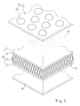
- the performance textile mainly includes a flexible fabric 10 and a gas permeable fabric 20.
- the flexible fabric 10 has a joining surface 11.
- the gas permeable fabric 20 is arranged on the flexible fabric 10, and includes a plurality of contact regions 21 and a plurality of bulged regions 22.
- the contact regions 21 connect to the joining surfaces 11.
- the bulged regions 22 are adjacent to the contact regions 21 and form a chamber 30 with the joining surface 11 to contain gas penetrated from the bulged regions 22 of the gas permeable fabric 20.
- Each of the bulged regions 22 includes a peripheral portion 221 and an upper portion 222.
- the peripheral portion 221 is adjacent to the contact regions 21.
- the upper portion 222 is extended from the peripheral portion 221 and has an outer diameter smaller than the peripheral portion 221 such that each bulged region 22 is formed in a semispherical shape.
- the bulged regions 22 are arranged as a regular pattern in two dimensions. But this is not the limitation, an irregular pattern may also be formed according to the requirement of design.
- the flexible fabric 10 is bonded to the gas permeable fabric 20 through an adhesive layer 40.
- the adhesive layer 40 may be a moisture-cure gel, preferably polyurethane (PU) or polymethylmethacrylate (PMMA) printing on the joining surface 11 by roller printing, knife printing or spreading methods to bind with the gas permeable fabric 20.
- the moisture cure gel is cured to form the adhesive layer 40 which has a plurality of bonding regions 41 and a plurality of non-bonding regions 42 complementary to the bonding regions 41.
- the bonding regions 41 allow the joining surface 11 to form a tight bonding with the contact region 21.
- the flexible fabric 10 and the gas permeable fabric 20 may also be bonded together mechanically by various weaving or knitting processes.
- the flexible fabric 10 includes a top layer 12, a bottom layer 13 and a support layer 14 interposed between the top layer 12 and bottom layer 13.
- the top layer 12 is connected to the gas permeable fabric 20 through the adhesive layer 40.
- the support layer 14 includes a plurality of support sections 141 with two ends connecting respectively to the top layer 12 and bottom layer 13. Besides, an angle is formed between the support sections 141 in a range between 10° to 90°.
- a pliable layer 50 may be attached on a surface of the flexible fabric 10 opposite to the gas permeable fabric 20.
- the pliable layer 50 may be selected from a fabric with a soft touching feel with human's skin, yarns of the fabric may use cotton or a blend of cotton and synthetic fiber. Binding of the pliable layer 50 with the gas permeable fabric 20 may also be accomplished by chemical or mechanical means same as binding of the flexible fabric 10 to the gas permeable fabric 20.
- the bottom layer 13, top layer 12 and gas permeable fabric 20 can be made by weaving, knitting or crocheting.
- the bottom layer 13 and top layer 12 are preferably manufactured by a circular knitting machine in warp and weft directions respectively.
- the gas permeable fabric 20 is preferably made by a warp knitting machine to provide improved abrasion resistance.
- the bottom layer 13, top layer 12 and gas permeable fabric may be formed by elastic yarns, preferably Spandex fibers, nylon 6 fibers, nylon 6-6 fibers, polyethylene terephthalate (PET) fibers, polyurethane (PU) fibers, polyethylene (PE) fibers, polypropylene (PP) fibers, or combinations thereof.
- the support sections 141 are made of monofilament fibers, such as polyester fibers, polypropylene (PP) fibers, polyamide fibers, polyethylene (PE) fibers, polyacrylonitrile (PAN) fibers, polyethylene terephthalate (PET) fibers or combinations thereof.
- the support sections 141 are preferably connected to the bottom layer 13 and top layer 12 by tuck knitting.
- the flexible fabric 10 is in an un-stretched condition as shown in FIG. 2 .
- the chamber 30 remains the original profile.
- the flexible fabric 10 when the user is in action and the flexible fabric 10 receives a force in parallel with the joining surface 11, such as at the bending spot of joints or user's body in a stretching condition, the flexible fabric 10 is extended transversely in a stretched condition. Because the flexible fabric 10 and the gas permeable fabric 20 are bonded together, the gas permeable fabric 20 also is stretched transversely, and a relative displacement is generated between the contact regions 21 when the flexible fabric 10 changes from the un-stretched condition to stretched condition. The bulged regions 22 also move towards the joining surface 11, hence the chamber 30 is lowered to form a volume change.
- the volume change of the chamber 30 generates a pressure difference inside that the internal pressure thereof, namely the internal pressure of the chamber 30 is increased to force the gas to flow downwards, and part of the flexible fabric 10 corresponding to the bulged regions 22 form a passage that provides the gas to flow towards user's skin through the pliable layer 50 as shown by downward arrows. While the gas passes through the pliable layer 50 to a gap between the pliable layer 50 and user's skin, another gas pressure is formed in the gap to make vapors coming from sweat produced by user's skin to expel through the contact regions 21.
- part of the flexible fabric 10 corresponding to the contact regions 21 form a passage to allow the vapors to be expelled from the user's skin as shown by the upward arrows in FIG. 3 . Therefore a gas circulation is formed between the gas from exterior and the vapors from the sweat through the passages to perform heat exchange between the performance textile and user's skin when the user is in action.
- the flexible fabric 20 is manufactured in another fashion with the upper portions 222a of the bulged regions 22 formed at a diameter larger than the peripheral portion 221 a so that each bulged region 22 is formed in a water drop shape as shown in Fig. 4 .
- the bonding region 41 of the adhesive layer 40 may be selectively formed on the joining surface 11.
- the adhesive layer 40 has a plurality of blank regions 43 corresponding to the bulged region 22. This can be done by using a screen printing method or the like during applying the moisture cure gel.
- the performance textile of the present invention thus formed provides desired gas permeability and can cushion impact. Tests have been made based on the embodiments as follow. They serve merely for illustrative purpose, and are not the limitations of the present invention.
- the gas permeable fabric 20 is formed according to the structure shown in FIG. 2 made by the warp knitting machine.
- the yarn of the gas permeable fabric 20 is formed by blending nylon 6 fibers with PU fibers which are in 70 denier and 40 denier respectively.
- the top layer 12 and bottom layer 13 are formed by circular knitting machines through the blended yarn of nylon 6 fibers and PU fibers which are in 50 denier and 40 denier respectively.
- the support sections 141 are monofilament PET fibers, and joined with the top layer 12 and bottom layer 13 by tuck knitting.
- the adhesive layer 40 is a moisture cure gel of PU.
- the denier previously discussed means the mass in grams per 9000 meters.
- Test of gas permeability and impact resistance adopts textile gas permeability test method ASTM D737 made by ASTM (American Society for Testing and Materials) and by using an impact testing machine respectively. Neoprene is used as a control group to compare with the embodiment of the present invention. Results of the test are shown in Table 1 below, where ASTM D737 measures volume of the gas passed through in unit of cfm (cubic feet per minute). In the impact resistance test, impact energy is six Joule, the loading kN (Kilonewtons) on the other side opposite to impact surface of the gas permeable fabric 20 is determined in the impact test. Table 1 ASTM D737 Impact resistance test Embodiment 34.90cfm 10.3 kN control group 0 cfin 17.4 kN
- the gas can pass the performance textile of the embodiment at a value of 34.90 cfm in the ASTM D737 test while the control group is zero.
- the loading of the embodiment of the performance textile worn by a user is 10.3kN, while Neoprene is 17.4 kN.
- the test results show that the embodiment of the present invention has improvements both on gas permeability and impact resistance over Neoprene.
- the performance textile having gas permeable and protective functions employs a design of bulged regions to form the chamber which can retract and expand during movement of human body to generate volume change and the pressure difference so that the gas can be channeled to user's muscles and skin to rapidly expel heated gas generated thereof.
- the pressure difference still can force the gas to pass through the flexible fabric to create a circulation between the gas from exterior and the vapors from the sweat.
- the three-dimensional structure of the bulged regions and support sections can reduce external impact on human body and avert injury, thus provide both greater gas permeability and enhanced protection.
- the bottom and top layer of the flexible fabric can be knitted respectively in weft and warp directions. Incorporating with the support sections, the performance textile provides an excellent ability to stretch in three dimensions, thus enables users to move freely without constraint.
- the gas permeable fabric can be made by warp knitting to improve abrasion resistance. All this provides a greater improvement over the conventional techniques.
Landscapes
- Professional, Industrial, Or Sporting Protective Garments (AREA)
- Laminated Bodies (AREA)
Description
- The present invention relates to a performance textile and particularly to a performance textile equipped with enhanced gas permeability and protective function.
- Performance textile generally refer to textiles equipped with specific functions such as water-tightness, gas permeability, ultraviolet light-resistance, impact resistance, abrasion-resistance, low weight or the like. It is widely used in recreational or specialty applications. For those used in active sports, mountaineering or police, military and fire fighters in duty, wearing garments or protective outfits made from performance fabrics capable of absorbing impact usually is needed. These fabrics now being developed mainly are made from impact-absorbing material or equipped with a cushion structure to
- For instance,
U.S. patent 4,292,263 discloses a method of producing a foamed polyurethane body-protecting pad which includes a terry knit tube and a foam pad attached to an outer surface thereof. The foam pad is made from polyurethane (PU).U.S. patent 6,192,519 discloses an athletic sports pad which includes a tubular member and a high friction material located on the tubular member. The tubular member includes a padded section and an un-padded portion. The padded section has a pad made from foamed polymers to provide protective function. -
U.S. patent 6,122,768 discloses a joint protector for use in active sports. It includes a cushion pad, a semi-rigid cap and a flexible cover which are arranged from inside to outside. The cushion pad is made from foamed polyethylene (PE) or polyurethane (PU). The cap is made from polyvinyl chloride (PVC), polypropylene (PP) or polyethylene (PE) that is formed at a selected thickness by injection molding process.U.S. patent gazette No. 2009/0255037 discloses a protective covering which mainly includes a soft inner layer and a hard outer layer. The soft inner layer and hard outer layer are interposed by an intermediate layer. The soft inner layer and intermediate layer are made from foamed ethylene-vinyl acetate (EVA).U.S. patent 5,416,924 discloses a flexible protective padding which mainly includes a metal shield, foamed polymer and Neoprene rubber. - All the aforesaid performance fabrics use foamed polymers or elastic rubber and are formed at a selected thickness so as to provide impact resistant mechanical characteristics for use on protective pads. While they provide protective function for human body, they do not have desired gas permeability. When in use, people's skin feels uncomfortable due to sweltering. Perspiration generated during sport activities is difficult to be expellled from clothes or protective outfits. Hence they do not provide comfortable wearing for users.
-
WO 03/022085 A2 -
WO 97/33493 -
WO 99/49236 - It is an object of the present invention to further improve the performance textile according to the preamble of claim 1 to provide an improved heat exchange in the structure when the user is in action.
- The above and related problems are solved by a performance textile according to claim 1. Further advantageous embodiments are the subject-matter of the dependent claims.
- According to the present invention the problem of conventional protective performance fabrics is identified in that such fabrics have poor gas permeability and thus result in uncomfortable and sweltering feeling of users when exercising.
- To achieve the foregoing object the present invention provides a performance textile having gas permeable and protective functions that includes a flexible fabric and a gas permeable fabric. The flexible fabric includes a joining surface and can receive a force in parallel with the joining surface. The flexible fabric is in a stretched condition when being subjected to the force and in an un-stretched condition when the force is absent. The gas permeable fabric is arranged on the flexible fabric and includes a plurality of contact regions and a plurality of bulged regions. The contact regions connect to the joining surfaces. The bulged regions are adjacent to the contact regions and form a chamber with the joining surface to contain gas. A relative displacement is generated between the contact regions when the flexible fabric changes from the un-stretched -condition to the stretched conditions. According to the present invention the bulged regions move towards the joining surface to conform to the relative displacement to form a volume change of the chamber such that a pressure difference is created to force the gas to pass through the flexible fabric.
- In one embodiment of the present invention the flexible fabric also includes a bottom layer, a top layer and a support layer interposed between the bottom layer and top layer. The top layer is connected to the gas permeable fabric. The support layer includes a plurality of support sections with two ends connecting respectively to the bottom layer and top layer.
- By means of the structure set forth above the performance textile of the present invention provides many benefits over the conventional performance textiles, notably:
- 1. The structure of the present invention can transfer the force to the flexible fabric during actions of users to lower the bulged regions and accordingly increase the pressure inside the chamber, thus forces the gas to flow to the user's skin and improves gas permeability.
- 2. Another pressure difference also is formed at a space between the flexible fabric and user's skin to expel vapors of sweat excreted from user's skin through the textile, thus user's skin can feel cooler and more comfortable.
- 3. In addition to ventilation effect by forcing the gas flows, the bulged regions also provide protective function for user's body to absorb external impact and reduce injury that might otherwise occur.
- 4. The support sections arranged inside the flexible fabric can enhance cushion of external impact and also provide ability to stretch longitudinally during user movements. Incorporating with the transverse extensibility provided by different weaving directions of the bottom and top layers the flexible fabric can provide excellent ability to stretch in three-dimensional.
- The foregoing, as well as additional objects, features and advantages of the present invention will be more readily apparent from the following detailed description, which proceeds with reference to the accompanying drawings.
-
-
FIG. 1 is an exploded view of an embodiment of the performance textile having gas permeable and protective functions of the present invention. -
FIG. 2 is a sectional view of the embodiment of the textile of the present invention with the flexible fabric in an un-stretched condition. -
FIG. 3 is a sectional view of the embodiment of the textile of the present invention with the flexible fabric in a stretched condition. -
FIG. 4 is a sectional view of another embodiment of the textile of the present invention. - Please refer to
FIGS. 1 and2 respectively for an embodiment of the performance textile having gas permeable and protective functions of the present invention, and the embodiment of the textile of the present invention with the flexible fabric in an un-stretched condition. The performance textile mainly includes aflexible fabric 10 and a gaspermeable fabric 20. Theflexible fabric 10 has a joiningsurface 11. The gaspermeable fabric 20 is arranged on theflexible fabric 10, and includes a plurality ofcontact regions 21 and a plurality of bulgedregions 22. Thecontact regions 21 connect to the joining surfaces 11. The bulgedregions 22 are adjacent to thecontact regions 21 and form achamber 30 with the joiningsurface 11 to contain gas penetrated from the bulgedregions 22 of the gaspermeable fabric 20. Each of the bulgedregions 22 includes aperipheral portion 221 and anupper portion 222. Theperipheral portion 221 is adjacent to thecontact regions 21. Theupper portion 222 is extended from theperipheral portion 221 and has an outer diameter smaller than theperipheral portion 221 such that each bulgedregion 22 is formed in a semispherical shape. In this embodiment the bulgedregions 22 are arranged as a regular pattern in two dimensions. But this is not the limitation, an irregular pattern may also be formed according to the requirement of design. - In this embodiment, the
flexible fabric 10 is bonded to the gaspermeable fabric 20 through anadhesive layer 40. Theadhesive layer 40 may be a moisture-cure gel, preferably polyurethane (PU) or polymethylmethacrylate (PMMA) printing on the joiningsurface 11 by roller printing, knife printing or spreading methods to bind with the gaspermeable fabric 20. The moisture cure gel is cured to form theadhesive layer 40 which has a plurality ofbonding regions 41 and a plurality ofnon-bonding regions 42 complementary to thebonding regions 41. Thebonding regions 41 allow the joiningsurface 11 to form a tight bonding with thecontact region 21. Aside from forming chemical binding through theadhesive layer 40, theflexible fabric 10 and the gaspermeable fabric 20 may also be bonded together mechanically by various weaving or knitting processes. - Referring to
FIG. 2 , theflexible fabric 10 includes atop layer 12, abottom layer 13 and asupport layer 14 interposed between thetop layer 12 andbottom layer 13. Thetop layer 12 is connected to the gaspermeable fabric 20 through theadhesive layer 40. Thesupport layer 14 includes a plurality ofsupport sections 141 with two ends connecting respectively to thetop layer 12 andbottom layer 13. Besides, an angle is formed between thesupport sections 141 in a range between 10° to 90°. In addition, apliable layer 50 may be attached on a surface of theflexible fabric 10 opposite to the gaspermeable fabric 20. Thepliable layer 50 may be selected from a fabric with a soft touching feel with human's skin, yarns of the fabric may use cotton or a blend of cotton and synthetic fiber. Binding of thepliable layer 50 with the gaspermeable fabric 20 may also be accomplished by chemical or mechanical means same as binding of theflexible fabric 10 to the gaspermeable fabric 20. - The
bottom layer 13,top layer 12 and gaspermeable fabric 20 can be made by weaving, knitting or crocheting. In this embodiment, thebottom layer 13 andtop layer 12 are preferably manufactured by a circular knitting machine in warp and weft directions respectively. Thus thebottom layer 13 andtop layer 12 can have similar ability to stretch in directions on horizontal. The gaspermeable fabric 20 is preferably made by a warp knitting machine to provide improved abrasion resistance. Thebottom layer 13,top layer 12 and gas permeable fabric may be formed by elastic yarns, preferably Spandex fibers, nylon 6 fibers, nylon 6-6 fibers, polyethylene terephthalate (PET) fibers, polyurethane (PU) fibers, polyethylene (PE) fibers, polypropylene (PP) fibers, or combinations thereof. - The
support sections 141 are made of monofilament fibers, such as polyester fibers, polypropylene (PP) fibers, polyamide fibers, polyethylene (PE) fibers, polyacrylonitrile (PAN) fibers, polyethylene terephthalate (PET) fibers or combinations thereof. Thesupport sections 141 are preferably connected to thebottom layer 13 andtop layer 12 by tuck knitting. - In practice, when a user is in still or a state with small action, the
flexible fabric 10 is in an un-stretched condition as shown inFIG. 2 . Thechamber 30 remains the original profile. Referring toFIG. 3 , when the user is in action and theflexible fabric 10 receives a force in parallel with the joiningsurface 11, such as at the bending spot of joints or user's body in a stretching condition, theflexible fabric 10 is extended transversely in a stretched condition. Because theflexible fabric 10 and the gaspermeable fabric 20 are bonded together, the gaspermeable fabric 20 also is stretched transversely, and a relative displacement is generated between thecontact regions 21 when theflexible fabric 10 changes from the un-stretched condition to stretched condition. The bulgedregions 22 also move towards the joiningsurface 11, hence thechamber 30 is lowered to form a volume change. - Referring to
FIG. 3 , the volume change of thechamber 30 generates a pressure difference inside that the internal pressure thereof, namely the internal pressure of thechamber 30 is increased to force the gas to flow downwards, and part of theflexible fabric 10 corresponding to the bulgedregions 22 form a passage that provides the gas to flow towards user's skin through thepliable layer 50 as shown by downward arrows. While the gas passes through thepliable layer 50 to a gap between thepliable layer 50 and user's skin, another gas pressure is formed in the gap to make vapors coming from sweat produced by user's skin to expel through thecontact regions 21. That is, part of theflexible fabric 10 corresponding to thecontact regions 21 form a passage to allow the vapors to be expelled from the user's skin as shown by the upward arrows inFIG. 3 . Therefore a gas circulation is formed between the gas from exterior and the vapors from the sweat through the passages to perform heat exchange between the performance textile and user's skin when the user is in action. - Refer to
FIG. 4 for another embodiment of the performance textile of the present invention. Theflexible fabric 20 is manufactured in another fashion with theupper portions 222a of the bulgedregions 22 formed at a diameter larger than theperipheral portion 221 a so that each bulgedregion 22 is formed in a water drop shape as shown inFig. 4 . To reduce the impediment of the gas flowing to user's skin thebonding region 41 of theadhesive layer 40 may be selectively formed on the joiningsurface 11. As shown in the drawing, theadhesive layer 40 has a plurality ofblank regions 43 corresponding to the bulgedregion 22. This can be done by using a screen printing method or the like during applying the moisture cure gel. - The performance textile of the present invention thus formed provides desired gas permeability and can cushion impact. Tests have been made based on the embodiments as follow. They serve merely for illustrative purpose, and are not the limitations of the present invention.
- The gas
permeable fabric 20 is formed according to the structure shown inFIG. 2 made by the warp knitting machine. The yarn of the gaspermeable fabric 20 is formed by blending nylon 6 fibers with PU fibers which are in 70 denier and 40 denier respectively. Thetop layer 12 andbottom layer 13 are formed by circular knitting machines through the blended yarn of nylon 6 fibers and PU fibers which are in 50 denier and 40 denier respectively. Thesupport sections 141 are monofilament PET fibers, and joined with thetop layer 12 andbottom layer 13 by tuck knitting. Theadhesive layer 40 is a moisture cure gel of PU. The denier previously discussed means the mass in grams per 9000 meters. - Test of gas permeability and impact resistance adopts textile gas permeability test method ASTM D737 made by ASTM (American Society for Testing and Materials) and by using an impact testing machine respectively. Neoprene is used as a control group to compare with the embodiment of the present invention. Results of the test are shown in Table 1 below, where ASTM D737 measures volume of the gas passed through in unit of cfm (cubic feet per minute). In the impact resistance test, impact energy is six Joule, the loading kN (Kilonewtons) on the other side opposite to impact surface of the gas
permeable fabric 20 is determined in the impact test.Table 1 ASTM D737 Impact resistance test Embodiment 34.90cfm 10.3 kN control group 0 cfin 17.4 kN - As shown in the table, the gas can pass the performance textile of the embodiment at a value of 34.90 cfm in the ASTM D737 test while the control group is zero. On impact resistance test with six Joule, the loading of the embodiment of the performance textile worn by a user is 10.3kN, while Neoprene is 17.4 kN. The test results show that the embodiment of the present invention has improvements both on gas permeability and impact resistance over Neoprene.
- As a conclusion, the performance textile having gas permeable and protective functions according to the present invention employs a design of bulged regions to form the chamber which can retract and expand during movement of human body to generate volume change and the pressure difference so that the gas can be channeled to user's muscles and skin to rapidly expel heated gas generated thereof. Even with the support layer embedded in the flexible fabric, the pressure difference still can force the gas to pass through the flexible fabric to create a circulation between the gas from exterior and the vapors from the sweat. Meanwhile, the three-dimensional structure of the bulged regions and support sections can reduce external impact on human body and avert injury, thus provide both greater gas permeability and enhanced protection.
- The bottom and top layer of the flexible fabric can be knitted respectively in weft and warp directions. Incorporating with the support sections, the performance textile provides an excellent ability to stretch in three dimensions, thus enables users to move freely without constraint. The gas permeable fabric can be made by warp knitting to improve abrasion resistance. All this provides a greater improvement over the conventional techniques.
- While the preferred embodiments of the present invention have been set forth for the purpose of disclosure, modifications of the disclosed embodiments of the present invention as well as other embodiments thereof may occur to those skilled in the art. Accordingly, the appended claims are intended to cover all embodiments which do not depart from the spirit and scope of the present invention.
Claims (14)
- A performance textile having gas permeable and protective functions, comprising:a flexible fabric (10) which includes a joining surface (11), said flexible fabric (10) in a stretched condition when receiving a force in parallel with the joining surface (11), said flexible fabric (10) being in n un stretched condition when the force is absent; anda gas permeable fabric (20) which is arranged on the flexible fabric (10) and includes a plurality of contact regions (21) connecting to the joining surface (11) and a plurality of bulged regions (22) adjacent to the contact regions (21);the bulged regions (22) forming a chamber (30) with the joining surface (11) to contain gas, a relative displacement being generated between the contact regions (21) when the flexible fabric (10) changes from the un-stretched condition to the stretched condition;characterized in that the bulged regions (22) are configured to move towards the joining surface (11) to conform to the relative displacement to form a volume change of the chamber (30) such that a pressure difference is created to force the gas to pass through the flexible fabric (10).
- The performance textile of claim 1, wherein the flexible fabric (10) includes a bottom layer (13), a top layer (12) connecting to the gas permeable fabric (20) and a support layer (14) interposed between the bottom layer (13) and the top layer (12).
- The performance textile of claim 2, wherein the bottom layer (13) and the top layer (12) are Spandex fibers, nylon 6 fibers, nylon 6-6 fibers, polyethylene terephthalate fibers, polyurethane fibers, polyethylene fibers or polypropylene fibers.
- The performance textile of claim 2, wherein the support layer (14) includes a plurality of supporting fibers (141) with two opposite ends of the supporting fibers (141) connecting to the bottom layer (13) and the top layer (12) respectively.
- The performance textile of claim 4, wherein an angle is formed between the supporting fibers (141) in a range between 10° to 90°.
- The performance textile of claim 4, wherein the supporting fibers (141) are monofilament fibers selected from the group consisting of polyester fibers, polypropylene fibers, polyamide fibers, polyethylene fibers, polyacrylonitrile fibers and polyethylene terephthalate fibers.
- The performance textile of any of the preceding claims, wherein an adhesive layer (40) is attached onto the joining surface (11) which includes a plurality of bonding regions (41) joining the joining surface (11) to the contact regions (21).
- The performance textile of claim 7, wherein the adhesive layer includes a plurality of blank regions (43) corresponding to the bulged regions (22).
- The performance textile of claim 7, wherein the adhesive layer (40) is made selectively from polyurethane or polymethylmethacrylate.
- The performance textile of any of the preceding claims, wherein the gas permeable fabric (20) is made from Spandex fibers, nylon 6 fibers, nylon 6-6 fibers, polyethylene terephthalate fibers, polyurethane fibers, polyethylene fibers, polypropylene fibers or polypropylene fibers.
- The performance textile of any of the preceding claims, wherein each of the bulged regions (22) includes a peripheral portion (221, 221 a) in contact with the contact regions (21) and an upper portion (222, 222a) extended from the peripheral portion (221, 221 a).
- the performance textile of any of the preceding claims, wherein the upper portion (222a) is formed at a diameter greater than the peripheral portion (221a).
- The performance textile of any of the preceding claims, wherein the upper portion (222) is formed at a diameter smaller than the peripheral portion (221).
- The performance textile of any of the preceding claims, wherein a pliable layer (50) is attached on a surface of the flexible fabric (10) opposite to the gas permeable fabric (20).
Priority Applications (1)
| Application Number | Priority Date | Filing Date | Title |
|---|---|---|---|
| EP10165201A EP2394811B1 (en) | 2010-06-08 | 2010-06-08 | A performance textile having gas permeable and protective function |
Applications Claiming Priority (1)
| Application Number | Priority Date | Filing Date | Title |
|---|---|---|---|
| EP10165201A EP2394811B1 (en) | 2010-06-08 | 2010-06-08 | A performance textile having gas permeable and protective function |
Publications (2)
| Publication Number | Publication Date |
|---|---|
| EP2394811A1 EP2394811A1 (en) | 2011-12-14 |
| EP2394811B1 true EP2394811B1 (en) | 2012-08-29 |
Family
ID=42557336
Family Applications (1)
| Application Number | Title | Priority Date | Filing Date |
|---|---|---|---|
| EP10165201A Not-in-force EP2394811B1 (en) | 2010-06-08 | 2010-06-08 | A performance textile having gas permeable and protective function |
Country Status (1)
| Country | Link |
|---|---|
| EP (1) | EP2394811B1 (en) |
Cited By (1)
| Publication number | Priority date | Publication date | Assignee | Title |
|---|---|---|---|---|
| CN103445362A (en) * | 2013-09-16 | 2013-12-18 | 吴江市海丰喷织有限公司 | Multifunctional waterproof fabric |
Families Citing this family (5)
| Publication number | Priority date | Publication date | Assignee | Title |
|---|---|---|---|---|
| CN103932436A (en) * | 2014-04-02 | 2014-07-23 | 湖州森诺氟材料科技有限公司 | Ultrathin leisure fabric with windproof and breathable functions and manufacturing method thereof |
| JP6170481B2 (en) * | 2014-10-16 | 2017-07-26 | 株式会社カネマス | Knitting for clothes |
| CN104824889A (en) * | 2015-05-11 | 2015-08-12 | 湖州哲豪丝绸有限公司 | High-protection fabric structure |
| EP3525611B1 (en) * | 2016-09-28 | 2023-10-25 | Under Armour, Inc. | Apparel for athletic activities |
| CN111778733A (en) * | 2020-06-16 | 2020-10-16 | 清远市齐力合成革有限公司 | Soft shrinkage type polyurethane synthetic leather |
Family Cites Families (8)
| Publication number | Priority date | Publication date | Assignee | Title |
|---|---|---|---|---|
| US4292263A (en) | 1977-03-04 | 1981-09-29 | Zimmer Usa, Inc. | Method of producing a foamed polyurethane body-protecting pad |
| US5416924A (en) | 1991-09-19 | 1995-05-23 | Sims; Leon | Flexible protective padding |
| CZ289998A3 (en) * | 1996-03-15 | 1999-02-17 | The Procter & Gamble Company | Flexible and lightweight protective pad |
| US6122768A (en) | 1997-04-07 | 2000-09-26 | Mccrane; David P. | Joint protector for use in active sports |
| DE69808147T2 (en) * | 1998-03-20 | 2004-02-19 | Courtney, William Alexander, Altrincham | IMPROVED, ELASTOMERIC SHOCK ABSORBER WITH VISCOSE DAMPING |
| US6192519B1 (en) | 1999-03-19 | 2001-02-27 | Kathleen L. Coalter | Athletic sports pad |
| WO2003022085A2 (en) * | 2001-09-13 | 2003-03-20 | Daniel James Plant | Flexible energy absorbing material and methods of manufacture thereof |
| US7979918B2 (en) | 2008-02-14 | 2011-07-19 | Warrior Sports, Inc. | Protective covering |
-
2010
- 2010-06-08 EP EP10165201A patent/EP2394811B1/en not_active Not-in-force
Cited By (1)
| Publication number | Priority date | Publication date | Assignee | Title |
|---|---|---|---|---|
| CN103445362A (en) * | 2013-09-16 | 2013-12-18 | 吴江市海丰喷织有限公司 | Multifunctional waterproof fabric |
Also Published As
| Publication number | Publication date |
|---|---|
| EP2394811A1 (en) | 2011-12-14 |
Similar Documents
| Publication | Publication Date | Title |
|---|---|---|
| CN110167374B (en) | Waistband construction, method of forming a waistband support sheet, and garment support sheet | |
| EP2394811B1 (en) | A performance textile having gas permeable and protective function | |
| JP5976646B2 (en) | Flexible cushion pad, item incorporating the pad, and method of manufacture and use | |
| EP2967159B1 (en) | Protective ankle and calf sleeve | |
| US8281414B2 (en) | Garment having improved contact areas | |
| EP2150143B1 (en) | Articles of apparel providing enhanced body position feedback | |
| EP3167730B1 (en) | Wearable protection device | |
| CN104168784B (en) | Breathable impact-absorbing cushioning and construction | |
| JP2014526620A (en) | Sliding and wear-resistant flexible shock absorbing buffer pad, garment incorporating the pad, manufacturing method and method of use | |
| US9399164B2 (en) | Cycling suit with a seat pad | |
| US20220354202A1 (en) | Headgear | |
| CN106174821B (en) | Hard trousers pad | |
| WO2018144504A1 (en) | Spacer fabrics and methods of making the same | |
| US20110300350A1 (en) | Performance textile having gas permeable and protective functions | |
| KR20140028346A (en) | Multi functional sweatband | |
| CN119655545A (en) | Vamp with knitting functional element | |
| US20140106120A1 (en) | Two-dimensional composite element | |
| CN212708321U (en) | Wear-resistant gymnastics mat sandwich fabric | |
| CN2832234Y (en) | High-volume bamboo charcoal protective gear structure | |
| TWI354720B (en) | A performance textile having gas permeable and pro | |
| TWI785148B (en) | Cushion composite structure, pad body and personal protective equipment | |
| CN102275347A (en) | Functional cloth with high air permeability and protection | |
| ITUA20164534A1 (en) | TECHNICAL FABRIC | |
| CN220947005U (en) | Breathable heat-dissipation knitted fabric | |
| CN218790647U (en) | Clothes convenient to heat dissipation |
Legal Events
| Date | Code | Title | Description |
|---|---|---|---|
| 17P | Request for examination filed |
Effective date: 20100608 |
|
| AK | Designated contracting states |
Kind code of ref document: A1 Designated state(s): AL AT BE BG CH CY CZ DE DK EE ES FI FR GB GR HR HU IE IS IT LI LT LU LV MC MK MT NL NO PL PT RO SE SI SK SM TR |
|
| AX | Request for extension of the european patent |
Extension state: BA ME RS |
|
| PUAI | Public reference made under article 153(3) epc to a published international application that has entered the european phase |
Free format text: ORIGINAL CODE: 0009012 |
|
| RIN1 | Information on inventor provided before grant (corrected) |
Inventor name: WEN, WEN-TSAO |
|
| GRAP | Despatch of communication of intention to grant a patent |
Free format text: ORIGINAL CODE: EPIDOSNIGR1 |
|
| RIC1 | Information provided on ipc code assigned before grant |
Ipc: B32B 3/28 20060101ALI20120103BHEP Ipc: B32B 3/12 20060101AFI20120103BHEP Ipc: A41D 31/00 20060101ALI20120103BHEP Ipc: B32B 5/26 20060101ALI20120103BHEP |
|
| GRAS | Grant fee paid |
Free format text: ORIGINAL CODE: EPIDOSNIGR3 |
|
| GRAA | (expected) grant |
Free format text: ORIGINAL CODE: 0009210 |
|
| AK | Designated contracting states |
Kind code of ref document: B1 Designated state(s): AL AT BE BG CH CY CZ DE DK EE ES FI FR GB GR HR HU IE IS IT LI LT LU LV MC MK MT NL NO PL PT RO SE SI SK SM TR |
|
| REG | Reference to a national code |
Ref country code: GB Ref legal event code: FG4D |
|
| REG | Reference to a national code |
Ref country code: CH Ref legal event code: EP |
|
| REG | Reference to a national code |
Ref country code: AT Ref legal event code: REF Ref document number: 572834 Country of ref document: AT Kind code of ref document: T Effective date: 20120915 |
|
| REG | Reference to a national code |
Ref country code: IE Ref legal event code: FG4D |
|
| REG | Reference to a national code |
Ref country code: DE Ref legal event code: R096 Ref document number: 602010002596 Country of ref document: DE Effective date: 20121025 |
|
| REG | Reference to a national code |
Ref country code: AT Ref legal event code: MK05 Ref document number: 572834 Country of ref document: AT Kind code of ref document: T Effective date: 20120829 |
|
| REG | Reference to a national code |
Ref country code: NL Ref legal event code: VDEP Effective date: 20120829 |
|
| REG | Reference to a national code |
Ref country code: LT Ref legal event code: MG4D Effective date: 20120829 |
|
| PG25 | Lapsed in a contracting state [announced via postgrant information from national office to epo] |
Ref country code: HR Free format text: LAPSE BECAUSE OF FAILURE TO SUBMIT A TRANSLATION OF THE DESCRIPTION OR TO PAY THE FEE WITHIN THE PRESCRIBED TIME-LIMIT Effective date: 20120829 Ref country code: NO Free format text: LAPSE BECAUSE OF FAILURE TO SUBMIT A TRANSLATION OF THE DESCRIPTION OR TO PAY THE FEE WITHIN THE PRESCRIBED TIME-LIMIT Effective date: 20121129 Ref country code: IS Free format text: LAPSE BECAUSE OF FAILURE TO SUBMIT A TRANSLATION OF THE DESCRIPTION OR TO PAY THE FEE WITHIN THE PRESCRIBED TIME-LIMIT Effective date: 20121229 Ref country code: FI Free format text: LAPSE BECAUSE OF FAILURE TO SUBMIT A TRANSLATION OF THE DESCRIPTION OR TO PAY THE FEE WITHIN THE PRESCRIBED TIME-LIMIT Effective date: 20120829 Ref country code: AT Free format text: LAPSE BECAUSE OF FAILURE TO SUBMIT A TRANSLATION OF THE DESCRIPTION OR TO PAY THE FEE WITHIN THE PRESCRIBED TIME-LIMIT Effective date: 20120829 Ref country code: LT Free format text: LAPSE BECAUSE OF FAILURE TO SUBMIT A TRANSLATION OF THE DESCRIPTION OR TO PAY THE FEE WITHIN THE PRESCRIBED TIME-LIMIT Effective date: 20120829 |
|
| PG25 | Lapsed in a contracting state [announced via postgrant information from national office to epo] |
Ref country code: GR Free format text: LAPSE BECAUSE OF FAILURE TO SUBMIT A TRANSLATION OF THE DESCRIPTION OR TO PAY THE FEE WITHIN THE PRESCRIBED TIME-LIMIT Effective date: 20121130 Ref country code: LV Free format text: LAPSE BECAUSE OF FAILURE TO SUBMIT A TRANSLATION OF THE DESCRIPTION OR TO PAY THE FEE WITHIN THE PRESCRIBED TIME-LIMIT Effective date: 20120829 Ref country code: PT Free format text: LAPSE BECAUSE OF FAILURE TO SUBMIT A TRANSLATION OF THE DESCRIPTION OR TO PAY THE FEE WITHIN THE PRESCRIBED TIME-LIMIT Effective date: 20121231 Ref country code: SE Free format text: LAPSE BECAUSE OF FAILURE TO SUBMIT A TRANSLATION OF THE DESCRIPTION OR TO PAY THE FEE WITHIN THE PRESCRIBED TIME-LIMIT Effective date: 20120829 Ref country code: BE Free format text: LAPSE BECAUSE OF FAILURE TO SUBMIT A TRANSLATION OF THE DESCRIPTION OR TO PAY THE FEE WITHIN THE PRESCRIBED TIME-LIMIT Effective date: 20120829 Ref country code: SI Free format text: LAPSE BECAUSE OF FAILURE TO SUBMIT A TRANSLATION OF THE DESCRIPTION OR TO PAY THE FEE WITHIN THE PRESCRIBED TIME-LIMIT Effective date: 20120829 |
|
| PG25 | Lapsed in a contracting state [announced via postgrant information from national office to epo] |
Ref country code: NL Free format text: LAPSE BECAUSE OF FAILURE TO SUBMIT A TRANSLATION OF THE DESCRIPTION OR TO PAY THE FEE WITHIN THE PRESCRIBED TIME-LIMIT Effective date: 20120829 Ref country code: RO Free format text: LAPSE BECAUSE OF FAILURE TO SUBMIT A TRANSLATION OF THE DESCRIPTION OR TO PAY THE FEE WITHIN THE PRESCRIBED TIME-LIMIT Effective date: 20120829 Ref country code: EE Free format text: LAPSE BECAUSE OF FAILURE TO SUBMIT A TRANSLATION OF THE DESCRIPTION OR TO PAY THE FEE WITHIN THE PRESCRIBED TIME-LIMIT Effective date: 20120829 Ref country code: CZ Free format text: LAPSE BECAUSE OF FAILURE TO SUBMIT A TRANSLATION OF THE DESCRIPTION OR TO PAY THE FEE WITHIN THE PRESCRIBED TIME-LIMIT Effective date: 20120829 Ref country code: DK Free format text: LAPSE BECAUSE OF FAILURE TO SUBMIT A TRANSLATION OF THE DESCRIPTION OR TO PAY THE FEE WITHIN THE PRESCRIBED TIME-LIMIT Effective date: 20120829 |
|
| PG25 | Lapsed in a contracting state [announced via postgrant information from national office to epo] |
Ref country code: PL Free format text: LAPSE BECAUSE OF FAILURE TO SUBMIT A TRANSLATION OF THE DESCRIPTION OR TO PAY THE FEE WITHIN THE PRESCRIBED TIME-LIMIT Effective date: 20120829 Ref country code: SK Free format text: LAPSE BECAUSE OF FAILURE TO SUBMIT A TRANSLATION OF THE DESCRIPTION OR TO PAY THE FEE WITHIN THE PRESCRIBED TIME-LIMIT Effective date: 20120829 Ref country code: IT Free format text: LAPSE BECAUSE OF FAILURE TO SUBMIT A TRANSLATION OF THE DESCRIPTION OR TO PAY THE FEE WITHIN THE PRESCRIBED TIME-LIMIT Effective date: 20120829 |
|
| PLBE | No opposition filed within time limit |
Free format text: ORIGINAL CODE: 0009261 |
|
| STAA | Information on the status of an ep patent application or granted ep patent |
Free format text: STATUS: NO OPPOSITION FILED WITHIN TIME LIMIT |
|
| PG25 | Lapsed in a contracting state [announced via postgrant information from national office to epo] |
Ref country code: BG Free format text: LAPSE BECAUSE OF FAILURE TO SUBMIT A TRANSLATION OF THE DESCRIPTION OR TO PAY THE FEE WITHIN THE PRESCRIBED TIME-LIMIT Effective date: 20121129 |
|
| 26N | No opposition filed |
Effective date: 20130530 |
|
| REG | Reference to a national code |
Ref country code: DE Ref legal event code: R097 Ref document number: 602010002596 Country of ref document: DE Effective date: 20130530 |
|
| PG25 | Lapsed in a contracting state [announced via postgrant information from national office to epo] |
Ref country code: ES Free format text: LAPSE BECAUSE OF FAILURE TO SUBMIT A TRANSLATION OF THE DESCRIPTION OR TO PAY THE FEE WITHIN THE PRESCRIBED TIME-LIMIT Effective date: 20121210 |
|
| PG25 | Lapsed in a contracting state [announced via postgrant information from national office to epo] |
Ref country code: CY Free format text: LAPSE BECAUSE OF FAILURE TO SUBMIT A TRANSLATION OF THE DESCRIPTION OR TO PAY THE FEE WITHIN THE PRESCRIBED TIME-LIMIT Effective date: 20120829 |
|
| PG25 | Lapsed in a contracting state [announced via postgrant information from national office to epo] |
Ref country code: MC Free format text: LAPSE BECAUSE OF FAILURE TO SUBMIT A TRANSLATION OF THE DESCRIPTION OR TO PAY THE FEE WITHIN THE PRESCRIBED TIME-LIMIT Effective date: 20120829 |
|
| REG | Reference to a national code |
Ref country code: IE Ref legal event code: MM4A |
|
| REG | Reference to a national code |
Ref country code: FR Ref legal event code: ST Effective date: 20140228 |
|
| PG25 | Lapsed in a contracting state [announced via postgrant information from national office to epo] |
Ref country code: IE Free format text: LAPSE BECAUSE OF NON-PAYMENT OF DUE FEES Effective date: 20130608 |
|
| PG25 | Lapsed in a contracting state [announced via postgrant information from national office to epo] |
Ref country code: FR Free format text: LAPSE BECAUSE OF NON-PAYMENT OF DUE FEES Effective date: 20130701 |
|
| REG | Reference to a national code |
Ref country code: CH Ref legal event code: PL |
|
| GBPC | Gb: european patent ceased through non-payment of renewal fee |
Effective date: 20140608 |
|
| PG25 | Lapsed in a contracting state [announced via postgrant information from national office to epo] |
Ref country code: MT Free format text: LAPSE BECAUSE OF FAILURE TO SUBMIT A TRANSLATION OF THE DESCRIPTION OR TO PAY THE FEE WITHIN THE PRESCRIBED TIME-LIMIT Effective date: 20120829 |
|
| PG25 | Lapsed in a contracting state [announced via postgrant information from national office to epo] |
Ref country code: LI Free format text: LAPSE BECAUSE OF NON-PAYMENT OF DUE FEES Effective date: 20140630 Ref country code: CH Free format text: LAPSE BECAUSE OF NON-PAYMENT OF DUE FEES Effective date: 20140630 |
|
| PG25 | Lapsed in a contracting state [announced via postgrant information from national office to epo] |
Ref country code: GB Free format text: LAPSE BECAUSE OF NON-PAYMENT OF DUE FEES Effective date: 20140608 Ref country code: SM Free format text: LAPSE BECAUSE OF FAILURE TO SUBMIT A TRANSLATION OF THE DESCRIPTION OR TO PAY THE FEE WITHIN THE PRESCRIBED TIME-LIMIT Effective date: 20120829 |
|
| PG25 | Lapsed in a contracting state [announced via postgrant information from national office to epo] |
Ref country code: TR Free format text: LAPSE BECAUSE OF FAILURE TO SUBMIT A TRANSLATION OF THE DESCRIPTION OR TO PAY THE FEE WITHIN THE PRESCRIBED TIME-LIMIT Effective date: 20120829 |
|
| PG25 | Lapsed in a contracting state [announced via postgrant information from national office to epo] |
Ref country code: LU Free format text: LAPSE BECAUSE OF NON-PAYMENT OF DUE FEES Effective date: 20130608 Ref country code: MK Free format text: LAPSE BECAUSE OF FAILURE TO SUBMIT A TRANSLATION OF THE DESCRIPTION OR TO PAY THE FEE WITHIN THE PRESCRIBED TIME-LIMIT Effective date: 20120829 Ref country code: HU Free format text: LAPSE BECAUSE OF FAILURE TO SUBMIT A TRANSLATION OF THE DESCRIPTION OR TO PAY THE FEE WITHIN THE PRESCRIBED TIME-LIMIT; INVALID AB INITIO Effective date: 20100608 |
|
| PG25 | Lapsed in a contracting state [announced via postgrant information from national office to epo] |
Ref country code: AL Free format text: LAPSE BECAUSE OF FAILURE TO SUBMIT A TRANSLATION OF THE DESCRIPTION OR TO PAY THE FEE WITHIN THE PRESCRIBED TIME-LIMIT Effective date: 20120829 |
|
| PGFP | Annual fee paid to national office [announced via postgrant information from national office to epo] |
Ref country code: DE Payment date: 20190628 Year of fee payment: 10 |
|
| REG | Reference to a national code |
Ref country code: DE Ref legal event code: R119 Ref document number: 602010002596 Country of ref document: DE |
|
| PG25 | Lapsed in a contracting state [announced via postgrant information from national office to epo] |
Ref country code: DE Free format text: LAPSE BECAUSE OF NON-PAYMENT OF DUE FEES Effective date: 20210101 |